EP1707355A2 - Unité d'impression d'une machine d'impression sans dispositif de mouillage - Google Patents
Unité d'impression d'une machine d'impression sans dispositif de mouillage Download PDFInfo
- Publication number
- EP1707355A2 EP1707355A2 EP06116409A EP06116409A EP1707355A2 EP 1707355 A2 EP1707355 A2 EP 1707355A2 EP 06116409 A EP06116409 A EP 06116409A EP 06116409 A EP06116409 A EP 06116409A EP 1707355 A2 EP1707355 A2 EP 1707355A2
- Authority
- EP
- European Patent Office
- Prior art keywords
- printing unit
- blanket
- printing
- transfer cylinder
- plate
- Prior art date
- Legal status (The legal status is an assumption and is not a legal conclusion. Google has not performed a legal analysis and makes no representation as to the accuracy of the status listed.)
- Granted
Links
Images


Classifications
-
- B—PERFORMING OPERATIONS; TRANSPORTING
- B41—PRINTING; LINING MACHINES; TYPEWRITERS; STAMPS
- B41N—PRINTING PLATES OR FOILS; MATERIALS FOR SURFACES USED IN PRINTING MACHINES FOR PRINTING, INKING, DAMPING, OR THE LIKE; PREPARING SUCH SURFACES FOR USE AND CONSERVING THEM
- B41N6/00—Mounting boards; Sleeves Make-ready devices, e.g. underlays, overlays; Attaching by chemical means, e.g. vulcanising
-
- B—PERFORMING OPERATIONS; TRANSPORTING
- B41—PRINTING; LINING MACHINES; TYPEWRITERS; STAMPS
- B41F—PRINTING MACHINES OR PRESSES
- B41F13/00—Common details of rotary presses or machines
- B41F13/08—Cylinders
- B41F13/193—Transfer cylinders; Offset cylinders
-
- B—PERFORMING OPERATIONS; TRANSPORTING
- B41—PRINTING; LINING MACHINES; TYPEWRITERS; STAMPS
- B41N—PRINTING PLATES OR FOILS; MATERIALS FOR SURFACES USED IN PRINTING MACHINES FOR PRINTING, INKING, DAMPING, OR THE LIKE; PREPARING SUCH SURFACES FOR USE AND CONSERVING THEM
- B41N10/00—Blankets or like coverings; Coverings for wipers for intaglio printing
- B41N10/02—Blanket structure
- B41N10/06—Blanket structure facilitating fastening to, or location on, supports
-
- B—PERFORMING OPERATIONS; TRANSPORTING
- B41—PRINTING; LINING MACHINES; TYPEWRITERS; STAMPS
- B41N—PRINTING PLATES OR FOILS; MATERIALS FOR SURFACES USED IN PRINTING MACHINES FOR PRINTING, INKING, DAMPING, OR THE LIKE; PREPARING SUCH SURFACES FOR USE AND CONSERVING THEM
- B41N10/00—Blankets or like coverings; Coverings for wipers for intaglio printing
Definitions
- the invention relates to a printing unit of a printing press without dampening unit according to the preamble of claim 1.
- Some printing units work without dampening solution and are thus particularly suitable for waterless web offset printing.
- a printing plate which allows the transfer of the printed image without dampening solution.
- the printing plate on a lower layer of a ink-accepting material and an upper layer of a ink-repellent material.
- the ink repellency on the upper layer is carried out without dampening solution.
- special materials are required to make the top layer.
- silicone-containing materials have proven suitable for damp-proof ink repellency.
- the upper and thus ink-repellent layer of the printing plate has openings on the areas of the printed image to be printed, so that the printing ink can accumulate on the underlying ink-accepting layer.
- the printed image in generic printing on a downstream transfer cylinder, such as a blanket cylinder, are transmitted.
- the upper layer covers the lower layer so that no ink is transferred in these areas.
- a printing unit for waterless offset printing is for example in the WO 03/045695 A1 described.
- the EP 0 182 156 B1 shows a rubber cylinder with a radius reduced Area.
- the DE 198 02 470 A1 discloses a multilayer blanket.
- the DE 33 15 506 A1 describes an offset blanket, which has between its ends a recess extending in the axial direction in order to avoid Mitdrucken the plate edges.
- the invention has for its object to provide a printing unit of a printing press without dampening.
- An advantage of the printing unit is in particular that the ends of the printing plates opposite recesses on the lateral surface of the transfer cylinder, which extend parallel to the longitudinal axis of the transfer cylinder. In this way, a transfer of ink from the ends of the printing plates is prevented on the transfer cylinder. As a result, the ends of the printing plates are not printed in the planographic printing without fountain solution, as a color transfer of this area is excluded due to the wells on the transfer cylinder.
- the transfer cylinder is designed constructively, is basically arbitrary.
- the transfer cylinder on a blanket with a dimensionally stable support plate and a fixed to the support plate coating.
- the ends of the carrier plate can be fixed to the transfer cylinder.
- the lateral surface of the transfer cylinder is formed by the outside of the coating.
- a recess on the transfer cylinder can be formed by the distance between the leading end and the trailing end of the blanket, in particular by the distance between the leading side edge and the trailing side edge of the coating of the blanket.
- the coating between the leading end and the trailing end of the blanket, in particular between the leading side edge and the trailing side edge of the coating of the blanket, in particular approximately midway between these two side edges, have a groove incorporated into the coating of the blanket.
- the depth of the groove should preferably correspond to approximately 5% to 15% of the thickness of the coating.
- the ends are set even on the transfer cylinder.
- a recess may be formed by the distance between the leading and the trailing hemming edge of the blanket.
- the width of the groove in the circumferential direction should be about 0.1% to 1% of the length of the Compressed blanket in the circumferential direction.
- the plate cylinder and / or the transfer cylinder can be tempered, since the ink transfer process of the inkless ink can be better guided by the temperature control.
- a part of a printing unit 01 with a plate cylinder 02 and an adjacent transfer cylinder 03 is shown in a perspective view.
- On the circumference of the plate cylinder 02 are in four rows next to each other two printing plates 04, in particular planographic printing plates 04, mounted one behind the other in the circumferential direction, so that a total of eight printing plates 04 on the plate cylinder 02 results.
- the printing plates 04 transfer the desired print image in damp-proof flat printing onto the circumferential surface of the transfer cylinder 03, from where it is transferred, for example, to a printing material web in offset printing.
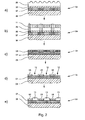
- the pressure plate 04 from a support layer 06 for example made of aluminum, a color transfer layer 07 of a color-transferring material, an ink-repellent layer 08 of an ink-repellent material, eg. B. silicone, and a protective layer 09.Zur transfer of the desired print image on the printing plate 04, this example, using a positive film 11 containing the printed image exposed (Fig. 2b).
- a positive film 11 containing the printed image exposed Fig. 2b
- UV light can be used.
- the ink-repellent layer 08 dissolves locally limited (FIG. 2 c) and can be washed off in areas with suitable solvents.
- the ink-repellent layer 08 covers the ink-transferring layer 07 at the locations of the printed image, which are not to be printed later ( Figure 2d).
- the ink 13 can accumulate in the region of the perforations 12 on the ink-transferring layer 07 and thus be transferred to the downstream transfer cylinder 03 (FIG. 2e).
- a damp-free transfer of the printing ink 13 is possible.
- other manufacturing processes are also known and can be used to produce printing plates that operate without dampening agents.
- the circumference of the transfer cylinder 03 is covered with a blanket 14.
- a recess 15 on the transfer cylinder 03 is formed by the distance between the leading end and the trailing end of the blanket 14.
- the plate cylinder 02 has channels 16, which can be flowed through by a temperature-controlled liquid, thereby tempering the plate cylinder 02 from the inside.
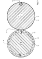
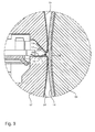
- the contact zone between the plate cylinder 02 and transfer cylinder 03 in which the successively arranged printing plates 04 are ink-transferring to the blanket 14 to the plant, is shown in Fig. 4 enlarged.
- the pressure plates 04 arranged one behind the other are respectively fixed with fastening tabs 18 on the plate cylinder 02.
- the blanket 14 has in the region of the circumference on which the ends 17 of the printing plates 04 roll on a recess 19, so that in the region of the ends 17 no ink is transferred to the blanket 14.
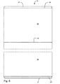
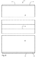
- the structure of the printing blanket 14 is shown in FIGS. 5 and 6.
- This blanket is preferably on a in the DE 103 11 285 A or DE 198 03 809 A to use the described printing unit.
- a multilayer coating 22 of rubber is vulcanized on a dimensionally stable support plate 21 made of stainless steel.
- the recess 19 is formed by a groove which is arranged approximately centrally between the leading side edge 23 and the trailing side edge 24 of the coating 22.
- the depth 26 of the recess 19 is approximately 10% of the thickness of the coating 22.
- the width 27 of the recess 19 is approximately 0.5% of the effective length of the blanket 14, which corresponds in the present embodiment, the length of the coating 22 in the circumferential direction.
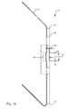
- a second embodiment of a transfer cylinder 28 is shown with a blanket 29 attached thereto in cross section.
- the ends of the blanket 29 are secured in a groove on the transfer cylinder 28.
- a lower 31 is arranged between the outer periphery of the transfer cylinder 28 and the inner periphery of the blanket 29.
- the banding 31 has an interruption, so that a recess 32 is thereby formed on the outer circumference of the blanket 29.
- the lateral surface of the transfer cylinder 28 may also have an interruption.
- a recess 19 is incorporated as a deformation in the carrier plate 21 of the blanket 14, d. H. at the point in which the recess 19 is formed on the support plate 21. In the recess 19 is in a dimensionally stable deformation.
- This deformation is in a first variant by means of a punch, z. B. a die 33, pressed into the support plate 21.
- the recess 19 is introduced into the carrier plate 21 by means of a male mold 34 and a die 33. Instead of the deformation and the thickness of the support plate 21 may be reduced.
- the recess 19 has a bending radius of about 0 mm to 1 mm.
- the width 27 is about 3 mm to 8 mm, wherein the depth 26 is about 0.1 mm to 0.5 mm, in particular about 0.2 mm to 0.3 mm.
- the recess 19 is mounted in an advantageous manner prior to the application of the blanket 14 on the dimensionally stable support plate 21 and prior to the application of the blanket 14 on the transfer cylinder 03 on the support plate 21.
- the depression 19 is introduced onto the carrier plate 21 on the carrier plate 21 when the blanket 14 has already been applied.
- the embodiments are also on transfer cylinder 03; 28 transferable, in which in the axial direction two blankets 14; 29 are arranged.
- the depressions 19; 32 are z. B. offset in the circumferential direction by 180 ° to each other.
- a plate cylinder 02 interacts, wherein a circumference of the transfer cylinder 03; 28 has an integer multiple of the circumference of the plate cylinder 02.
- the circumference of the plate cylinder 02 has a pressure plate 04 and four pressure plates 04 in the axial direction.
- the plate cylinder 02 may be associated with a dampening unit.
- the dimensionally stable support plate 21 is deformed together with the printing blanket 14 together with the aid of a die 33 and male part 34 to produce a depression 19.
- the printing blanket unit 37 consisting of carrier plate 21 and blanket 14 is introduced into a device 38.
- This device 38 essentially has a support 39, at least one or more hold-down 41, two movable, z. B. pivotable bending strips 42, the male 34 and the die 33 on.
- the hold-down 41, bending bars 42 and the male part 34 are, for example, each of a working cylinder 43, z. B. a pneumatic cylinder 43 moves.
- the printing blanket unit 37 is placed on the support 39 of the device 38 with the bending strips 42 open and fixed thereon with the hold-downs 41 (FIG. 12). Subsequently, the ends of the carrier plate 21 are preferably first bent by pivoting the bending bars 42 (FIG. 13) and then the recess 19 is formed by means of the male part 34 into the blanket unit 37 (FIG. 14).
Landscapes
- Engineering & Computer Science (AREA)
- Mechanical Engineering (AREA)
- Printing Plates And Materials Therefor (AREA)
- Rotary Presses (AREA)
Applications Claiming Priority (4)
| Application Number | Priority Date | Filing Date | Title |
|---|---|---|---|
| DE10358842 | 2003-12-16 | ||
| DE102004011882A DE102004011882A1 (de) | 2003-12-16 | 2004-03-11 | Druckwerk für eine Druckmaschine ohne Feuchtwerk sowie Drucktuch |
| DE200410023316 DE102004023316A1 (de) | 2004-05-07 | 2004-05-07 | Drucktuch mit einer formstabilen Trägerplatte, ein Verfahren zur Herstellung eines solchen Drucktuches sowie ein Druckwerk für eine Druckmaschine ohne Feuchtwerk |
| EP04804815A EP1694505B1 (fr) | 2003-12-16 | 2004-12-14 | Blanchet a plaque support indeformable, et procede de production d'un tel blanchet |
Related Parent Applications (1)
| Application Number | Title | Priority Date | Filing Date |
|---|---|---|---|
| EP04804815A Division EP1694505B1 (fr) | 2003-12-16 | 2004-12-14 | Blanchet a plaque support indeformable, et procede de production d'un tel blanchet |
Publications (3)
| Publication Number | Publication Date |
|---|---|
| EP1707355A2 true EP1707355A2 (fr) | 2006-10-04 |
| EP1707355A3 EP1707355A3 (fr) | 2007-07-25 |
| EP1707355B1 EP1707355B1 (fr) | 2009-07-08 |
Family
ID=34704621
Family Applications (2)
| Application Number | Title | Priority Date | Filing Date |
|---|---|---|---|
| EP04804815A Expired - Lifetime EP1694505B1 (fr) | 2003-12-16 | 2004-12-14 | Blanchet a plaque support indeformable, et procede de production d'un tel blanchet |
| EP06116409A Expired - Lifetime EP1707355B1 (fr) | 2003-12-16 | 2004-12-14 | Unité d'impression d'une machine d'impression sans dispositif de mouillage |
Family Applications Before (1)
| Application Number | Title | Priority Date | Filing Date |
|---|---|---|---|
| EP04804815A Expired - Lifetime EP1694505B1 (fr) | 2003-12-16 | 2004-12-14 | Blanchet a plaque support indeformable, et procede de production d'un tel blanchet |
Country Status (4)
| Country | Link |
|---|---|
| US (1) | US7533608B2 (fr) |
| EP (2) | EP1694505B1 (fr) |
| JP (1) | JP2007511389A (fr) |
| WO (1) | WO2005058601A2 (fr) |
Families Citing this family (17)
| Publication number | Priority date | Publication date | Assignee | Title |
|---|---|---|---|---|
| DE102004033920B4 (de) * | 2004-05-04 | 2006-11-02 | Koenig & Bauer Ag | Druckform einer Druckmaschine und Rollenrotationsdruckmaschine |
| DE102006010551A1 (de) * | 2006-03-07 | 2007-09-13 | Maschinenfabrik Wifag | Entlastungselement |
| DE102006027144B3 (de) * | 2006-06-12 | 2007-11-29 | Koenig & Bauer Aktiengesellschaft | Drucktucheinheit für einen Drucktuchzylinder einer Rotationsdruckmaschine |
| DE102006027142B3 (de) * | 2006-06-12 | 2007-05-24 | Koenig & Bauer Ag | Drucktucheinheit für einen Drucktuchzylinder einer Rotationsdruckmaschine |
| DE102006027143B4 (de) * | 2006-06-12 | 2011-06-01 | Koenig & Bauer Aktiengesellschaft | Drucktucheinheit für einen Drucktuchzylinder einer Rotationsdruckmaschine |
| DE102007009810A1 (de) * | 2007-02-28 | 2008-09-04 | Man Roland Druckmaschinen Ag | Übertragungsform für einen Übertragungszylinder einer Druckmaschine |
| DE102007010358A1 (de) * | 2007-03-03 | 2008-10-30 | Manroland Ag | Satellitendruckeinheit einer Rollendruckmaschine |
| ITMI20071348A1 (it) * | 2007-07-06 | 2009-01-07 | Trelleborg Engineered Systems | Metodo per la realizzazione di un rivestimento (metal back printing blanket) di cilindro tipografico con foglio plastico termoadesivo come sottorivestimento |
| JP2010036518A (ja) * | 2008-08-07 | 2010-02-18 | Lifcom:Kk | ブランケット胴 |
| JP5465886B2 (ja) * | 2009-01-21 | 2014-04-09 | 三菱重工印刷紙工機械株式会社 | 印刷用ブランケット及びその製造方法、ブランケット胴並びに印刷機 |
| JP5332017B2 (ja) * | 2009-08-19 | 2013-11-06 | 株式会社東京機械製作所 | 新聞印刷用ブランケット胴及びこのブランケット胴を備えた新聞印刷用オフセット輪転印刷機 |
| WO2011104832A1 (fr) * | 2010-02-24 | 2011-09-01 | 三菱重工印刷紙工機械株式会社 | Blanchet d'impression, son procédé de fabrication, tambour de blanchet et imprimante |
| US20120073460A1 (en) * | 2010-09-29 | 2012-03-29 | Goss International Americas, Inc. | Variable cutoff printing press and method for double printing |
| DE202013103877U1 (de) * | 2013-07-26 | 2013-10-18 | Manroland Web Systems Gmbh | Druckwerk und Kontaktstruktur für ein Druckwerk |
| DE102014208428B3 (de) * | 2014-05-06 | 2015-04-02 | Koenig & Bauer Aktiengesellschaft | Verfahren zum Ausbilden eines Drucktuches für eine Rotationsdruckmaschine |
| JP6410617B2 (ja) * | 2015-01-19 | 2018-10-24 | 西研グラフィックス株式会社 | ブランケット胴の製造方法 |
| JP6508680B2 (ja) * | 2015-07-24 | 2019-05-08 | 藤倉コンポジット株式会社 | 印刷用ブランケット |
Family Cites Families (24)
| Publication number | Priority date | Publication date | Assignee | Title |
|---|---|---|---|---|
| DE1947520A1 (de) | 1969-09-19 | 1971-11-04 | Claas Maschf Gmbh Geb | Aufgabevorrichtung fuer eine Foerdereinrichtung |
| GB1486473A (en) * | 1973-09-19 | 1977-09-21 | Gravure Res Inst Inc | Rotogravure printing apparatus |
| GB1476707A (en) | 1974-06-28 | 1977-06-16 | Rockwell International Corp | Printing plate arrangement |
| JPS58180043U (ja) * | 1982-05-26 | 1983-12-01 | 株式会社明治ゴム化成 | 印刷用ブランケツト |
| JPS5943166U (ja) * | 1982-09-13 | 1984-03-21 | 住友ゴム工業株式会社 | オフセツト印刷機用ブランケツト |
| DE3315506A1 (de) * | 1983-04-28 | 1984-10-31 | Siegfried Dipl.-Ing. Geiger (FH), 8039 Puchheim | Offset-tuch fuer den offset-zylinder des druckwerks einer offset-druckmaschine |
| DE3336193C2 (de) * | 1983-10-05 | 1986-02-27 | M.A.N.- Roland Druckmaschinen AG, 6050 Offenbach | Gummituch für eine Offsetrotationsdruckmaschine |
| DE3441175C2 (de) | 1984-11-10 | 1987-01-22 | Albert-Frankenthal Ag, 6710 Frankenthal | Gummituchzylinder für eine Offsetdruckmaschine |
| DE4217793C1 (de) * | 1992-05-29 | 1993-12-09 | Roland Man Druckmasch | Offset-Gummituch und Verfahren zu dessen Herstellung |
| JPH0717157A (ja) * | 1993-07-02 | 1995-01-20 | Mitsubishi Heavy Ind Ltd | ベース付ブランケット |
| JP3379801B2 (ja) * | 1993-11-25 | 2003-02-24 | 株式会社金陽社 | 印刷用ブランケットの製造方法 |
| DE4400020A1 (de) * | 1994-01-03 | 1995-08-31 | I M C Gmbh Marketing Fuer Die | Gummituch für Druckmaschinen, insbesondere für Rollenoffsetmaschinen, sowie Verfahren zu seiner Herstellung |
| FR2763888B1 (fr) * | 1997-05-28 | 1999-07-16 | Rollin Sa | Manchon perfectionne pour cylindre de machine d'impression ou analogue et procede de mise en place de ce manchon |
| DE19802470A1 (de) * | 1998-01-23 | 1999-07-29 | Contitech Elastomer Besch Gmbh | Drucktuch und Verfahren zu seiner Herstellung |
| DE19803809A1 (de) * | 1998-01-31 | 1999-08-05 | Roland Man Druckmasch | Offsetdruckwerk |
| DE19804269A1 (de) * | 1998-02-04 | 1999-08-05 | Heidelberger Druckmasch Ag | Vorrichtung zum Auftragen einer Flüssigkeit auf einen Bedruckstoffbogen, insbesondere Druck, oder Lackierwerk, in einer Bogenrotationsdruckmaschine |
| JP2000006543A (ja) * | 1998-06-23 | 2000-01-11 | Sumitomo Rubber Ind Ltd | 印刷用ブランケット |
| EP1334825B1 (fr) | 1999-12-02 | 2011-06-01 | Koenig & Bauer Aktiengesellschaft | Groupe d'impression d'une machine d'impression |
| JP3457932B2 (ja) * | 2000-07-31 | 2003-10-20 | 三菱重工業株式会社 | 円筒状ブランケット及びブランケット胴並びに印刷機 |
| JP3674500B2 (ja) * | 2000-11-24 | 2005-07-20 | 東洋製罐株式会社 | 円筒物品へのオフセット印刷方法とその装置 |
| JP2002293057A (ja) * | 2001-03-29 | 2002-10-09 | Mitsubishi Heavy Ind Ltd | 円筒状ブランケット及び印刷機 |
| EP1600290B1 (fr) * | 2001-11-22 | 2006-08-23 | Koenig & Bauer Aktiengesellschaft | Utilisation d'une encre d'imprimerie dans une unité d'impression |
| DE10218359B4 (de) | 2002-04-25 | 2007-06-14 | Koenig & Bauer Aktiengesellschaft | Verwendung einer Druckfarbe |
| JP2004262212A (ja) * | 2003-03-04 | 2004-09-24 | Sumitomo Rubber Ind Ltd | 印刷用ブランケット |
-
2004
- 2004-12-14 US US10/582,606 patent/US7533608B2/en not_active Expired - Fee Related
- 2004-12-14 JP JP2006538872A patent/JP2007511389A/ja active Pending
- 2004-12-14 WO PCT/EP2004/053457 patent/WO2005058601A2/fr not_active Ceased
- 2004-12-14 EP EP04804815A patent/EP1694505B1/fr not_active Expired - Lifetime
- 2004-12-14 EP EP06116409A patent/EP1707355B1/fr not_active Expired - Lifetime
Also Published As
| Publication number | Publication date |
|---|---|
| WO2005058601A3 (fr) | 2007-01-18 |
| EP1707355A3 (fr) | 2007-07-25 |
| EP1694505A2 (fr) | 2006-08-30 |
| EP1707355B1 (fr) | 2009-07-08 |
| US20070144380A1 (en) | 2007-06-28 |
| JP2007511389A (ja) | 2007-05-10 |
| WO2005058601A2 (fr) | 2005-06-30 |
| US7533608B2 (en) | 2009-05-19 |
| EP1694505B1 (fr) | 2010-08-04 |
Similar Documents
| Publication | Publication Date | Title |
|---|---|---|
| EP1707355B1 (fr) | Unité d'impression d'une machine d'impression sans dispositif de mouillage | |
| EP0225509B1 (fr) | Dispositif pour imprimer une bande | |
| EP1233864B1 (fr) | Element d'impression d'une presse rotative | |
| EP0936065B1 (fr) | Dispositif pour appliquer un liquide sur une feuille imprimé, notamment unité d'impression ou de lacquage dans une machine rotative d'impression pour feuilles | |
| EP0085751B1 (fr) | Machine rotative d'impression offset de feuilles | |
| DE3221066A1 (de) | Verfahren und einrichtung zum passgenauen aufziehen von flexiblen klischees auf druckwalzen | |
| EP0279295B1 (fr) | Unité d'encrage | |
| DE10066162B4 (de) | Druckwerk einer Rotationsdruckmaschine | |
| DE3221974C2 (de) | Verfahren zum Glätten bedruckter Flächen bei dickem Farbauftrag und Vorrichtung zur Durchführung desselben | |
| WO1996005058A1 (fr) | Cylindre rotatif d'impression serigraphique et son utilisation | |
| DE102004023316A1 (de) | Drucktuch mit einer formstabilen Trägerplatte, ein Verfahren zur Herstellung eines solchen Drucktuches sowie ein Druckwerk für eine Druckmaschine ohne Feuchtwerk | |
| EP1422061B1 (fr) | Cylindre porte-plaque avec un corps cylindrique et au moins une chemise tubulaire | |
| DE102004011882A1 (de) | Druckwerk für eine Druckmaschine ohne Feuchtwerk sowie Drucktuch | |
| DE102013103712A1 (de) | Druckwerk und Gummituchplatte für ein Druckwerk | |
| DE102007047781A1 (de) | Rollendruckmaschine | |
| DE102004011881B3 (de) | Druckwerk für eine Druckmaschine ohne Feuchtwerk | |
| EP1990191A2 (fr) | Presse d'impression rotative pour bandes | |
| DE102007010481B4 (de) | Bogenrotationsdruckmaschine | |
| EP2829402A2 (fr) | Unité d'impression offset et habillage pour le blanchet | |
| DE102008005588A1 (de) | Druckplatte und Verfahren zum Reduzieren von Plattenkanten-Abdrucken von Druckplatten | |
| DE102006044979A1 (de) | Druckwerk einer Druckmaschine |
Legal Events
| Date | Code | Title | Description |
|---|---|---|---|
| PUAI | Public reference made under article 153(3) epc to a published international application that has entered the european phase |
Free format text: ORIGINAL CODE: 0009012 |
|
| AC | Divisional application: reference to earlier application |
Ref document number: 1694505 Country of ref document: EP Kind code of ref document: P |
|
| AK | Designated contracting states |
Kind code of ref document: A2 Designated state(s): AT BE BG CH CY CZ DE DK EE ES FI FR GB GR HU IE IS IT LI LT LU MC NL PL PT RO SE SI SK TR |
|
| AX | Request for extension of the european patent |
Extension state: AL BA HR LV MK YU |
|
| PUAL | Search report despatched |
Free format text: ORIGINAL CODE: 0009013 |
|
| AK | Designated contracting states |
Kind code of ref document: A3 Designated state(s): AT BE BG CH CY CZ DE DK EE ES FI FR GB GR HU IE IS IT LI LT LU MC NL PL PT RO SE SI SK TR |
|
| AX | Request for extension of the european patent |
Extension state: AL BA HR LV MK YU |
|
| RIC1 | Information provided on ipc code assigned before grant |
Ipc: B41F 13/193 20060101ALI20070619BHEP Ipc: B41N 10/02 20060101AFI20070619BHEP Ipc: B41N 10/06 20060101ALI20070619BHEP |
|
| 17P | Request for examination filed |
Effective date: 20070629 |
|
| AKX | Designation fees paid |
Designated state(s): AT BE BG CH CY CZ DE DK EE ES FI FR GB GR HU IE IS IT LI LT LU MC NL PL PT RO SE SI SK TR |
|
| 17Q | First examination report despatched |
Effective date: 20081230 |
|
| GRAP | Despatch of communication of intention to grant a patent |
Free format text: ORIGINAL CODE: EPIDOSNIGR1 |
|
| GRAS | Grant fee paid |
Free format text: ORIGINAL CODE: EPIDOSNIGR3 |
|
| GRAA | (expected) grant |
Free format text: ORIGINAL CODE: 0009210 |
|
| AC | Divisional application: reference to earlier application |
Ref document number: 1694505 Country of ref document: EP Kind code of ref document: P |
|
| AK | Designated contracting states |
Kind code of ref document: B1 Designated state(s): AT BE BG CH CY CZ DE DK EE ES FI FR GB GR HU IE IS IT LI LT LU MC NL PL PT RO SE SI SK TR |
|
| REG | Reference to a national code |
Ref country code: GB Ref legal event code: FG4D Free format text: NOT ENGLISH |
|
| REG | Reference to a national code |
Ref country code: CH Ref legal event code: EP |
|
| REG | Reference to a national code |
Ref country code: IE Ref legal event code: FG4D |
|
| REF | Corresponds to: |
Ref document number: 502004009735 Country of ref document: DE Date of ref document: 20090820 Kind code of ref document: P |
|
| PG25 | Lapsed in a contracting state [announced via postgrant information from national office to epo] |
Ref country code: SI Free format text: LAPSE BECAUSE OF FAILURE TO SUBMIT A TRANSLATION OF THE DESCRIPTION OR TO PAY THE FEE WITHIN THE PRESCRIBED TIME-LIMIT Effective date: 20090708 |
|
| NLV1 | Nl: lapsed or annulled due to failure to fulfill the requirements of art. 29p and 29m of the patents act | ||
| PG25 | Lapsed in a contracting state [announced via postgrant information from national office to epo] |
Ref country code: LT Free format text: LAPSE BECAUSE OF FAILURE TO SUBMIT A TRANSLATION OF THE DESCRIPTION OR TO PAY THE FEE WITHIN THE PRESCRIBED TIME-LIMIT Effective date: 20090708 Ref country code: IS Free format text: LAPSE BECAUSE OF FAILURE TO SUBMIT A TRANSLATION OF THE DESCRIPTION OR TO PAY THE FEE WITHIN THE PRESCRIBED TIME-LIMIT Effective date: 20091108 Ref country code: ES Free format text: LAPSE BECAUSE OF FAILURE TO SUBMIT A TRANSLATION OF THE DESCRIPTION OR TO PAY THE FEE WITHIN THE PRESCRIBED TIME-LIMIT Effective date: 20091019 |
|
| REG | Reference to a national code |
Ref country code: IE Ref legal event code: FD4D |
|
| PG25 | Lapsed in a contracting state [announced via postgrant information from national office to epo] |
Ref country code: NL Free format text: LAPSE BECAUSE OF FAILURE TO SUBMIT A TRANSLATION OF THE DESCRIPTION OR TO PAY THE FEE WITHIN THE PRESCRIBED TIME-LIMIT Effective date: 20090708 Ref country code: PL Free format text: LAPSE BECAUSE OF FAILURE TO SUBMIT A TRANSLATION OF THE DESCRIPTION OR TO PAY THE FEE WITHIN THE PRESCRIBED TIME-LIMIT Effective date: 20090708 |
|
| PLBI | Opposition filed |
Free format text: ORIGINAL CODE: 0009260 |
|
| PG25 | Lapsed in a contracting state [announced via postgrant information from national office to epo] |
Ref country code: PT Free format text: LAPSE BECAUSE OF FAILURE TO SUBMIT A TRANSLATION OF THE DESCRIPTION OR TO PAY THE FEE WITHIN THE PRESCRIBED TIME-LIMIT Effective date: 20091109 Ref country code: BG Free format text: LAPSE BECAUSE OF FAILURE TO SUBMIT A TRANSLATION OF THE DESCRIPTION OR TO PAY THE FEE WITHIN THE PRESCRIBED TIME-LIMIT Effective date: 20091008 |
|
| PLAZ | Examination of admissibility of opposition: despatch of communication + time limit |
Free format text: ORIGINAL CODE: EPIDOSNOPE2 |
|
| 26 | Opposition filed |
Opponent name: MANROLAND AG Effective date: 20100323 |
|
| PG25 | Lapsed in a contracting state [announced via postgrant information from national office to epo] |
Ref country code: DK Free format text: LAPSE BECAUSE OF FAILURE TO SUBMIT A TRANSLATION OF THE DESCRIPTION OR TO PAY THE FEE WITHIN THE PRESCRIBED TIME-LIMIT Effective date: 20090708 Ref country code: RO Free format text: LAPSE BECAUSE OF FAILURE TO SUBMIT A TRANSLATION OF THE DESCRIPTION OR TO PAY THE FEE WITHIN THE PRESCRIBED TIME-LIMIT Effective date: 20090708 Ref country code: IE Free format text: LAPSE BECAUSE OF FAILURE TO SUBMIT A TRANSLATION OF THE DESCRIPTION OR TO PAY THE FEE WITHIN THE PRESCRIBED TIME-LIMIT Effective date: 20090708 Ref country code: EE Free format text: LAPSE BECAUSE OF FAILURE TO SUBMIT A TRANSLATION OF THE DESCRIPTION OR TO PAY THE FEE WITHIN THE PRESCRIBED TIME-LIMIT Effective date: 20090708 Ref country code: CZ Free format text: LAPSE BECAUSE OF FAILURE TO SUBMIT A TRANSLATION OF THE DESCRIPTION OR TO PAY THE FEE WITHIN THE PRESCRIBED TIME-LIMIT Effective date: 20090708 |
|
| PLBA | Examination of admissibility of opposition: reply received |
Free format text: ORIGINAL CODE: EPIDOSNOPE4 |
|
| PLAX | Notice of opposition and request to file observation + time limit sent |
Free format text: ORIGINAL CODE: EPIDOSNOBS2 |
|
| PG25 | Lapsed in a contracting state [announced via postgrant information from national office to epo] |
Ref country code: SK Free format text: LAPSE BECAUSE OF FAILURE TO SUBMIT A TRANSLATION OF THE DESCRIPTION OR TO PAY THE FEE WITHIN THE PRESCRIBED TIME-LIMIT Effective date: 20090708 |
|
| PLBB | Reply of patent proprietor to notice(s) of opposition received |
Free format text: ORIGINAL CODE: EPIDOSNOBS3 |
|
| BERE | Be: lapsed |
Owner name: KOENIG & BAUER A.G. Effective date: 20091231 |
|
| PG25 | Lapsed in a contracting state [announced via postgrant information from national office to epo] |
Ref country code: MC Free format text: LAPSE BECAUSE OF NON-PAYMENT OF DUE FEES Effective date: 20100701 |
|
| PG25 | Lapsed in a contracting state [announced via postgrant information from national office to epo] |
Ref country code: BE Free format text: LAPSE BECAUSE OF NON-PAYMENT OF DUE FEES Effective date: 20091231 Ref country code: GR Free format text: LAPSE BECAUSE OF FAILURE TO SUBMIT A TRANSLATION OF THE DESCRIPTION OR TO PAY THE FEE WITHIN THE PRESCRIBED TIME-LIMIT Effective date: 20091009 |
|
| PG25 | Lapsed in a contracting state [announced via postgrant information from national office to epo] |
Ref country code: FI Free format text: LAPSE BECAUSE OF FAILURE TO SUBMIT A TRANSLATION OF THE DESCRIPTION OR TO PAY THE FEE WITHIN THE PRESCRIBED TIME-LIMIT Effective date: 20090708 |
|
| PG25 | Lapsed in a contracting state [announced via postgrant information from national office to epo] |
Ref country code: IT Free format text: LAPSE BECAUSE OF FAILURE TO SUBMIT A TRANSLATION OF THE DESCRIPTION OR TO PAY THE FEE WITHIN THE PRESCRIBED TIME-LIMIT Effective date: 20090708 |
|
| PG25 | Lapsed in a contracting state [announced via postgrant information from national office to epo] |
Ref country code: LU Free format text: LAPSE BECAUSE OF NON-PAYMENT OF DUE FEES Effective date: 20091214 |
|
| PG25 | Lapsed in a contracting state [announced via postgrant information from national office to epo] |
Ref country code: AT Free format text: LAPSE BECAUSE OF NON-PAYMENT OF DUE FEES Effective date: 20091214 |
|
| PG25 | Lapsed in a contracting state [announced via postgrant information from national office to epo] |
Ref country code: HU Free format text: LAPSE BECAUSE OF FAILURE TO SUBMIT A TRANSLATION OF THE DESCRIPTION OR TO PAY THE FEE WITHIN THE PRESCRIBED TIME-LIMIT Effective date: 20100109 |
|
| PG25 | Lapsed in a contracting state [announced via postgrant information from national office to epo] |
Ref country code: TR Free format text: LAPSE BECAUSE OF FAILURE TO SUBMIT A TRANSLATION OF THE DESCRIPTION OR TO PAY THE FEE WITHIN THE PRESCRIBED TIME-LIMIT Effective date: 20090708 |
|
| PG25 | Lapsed in a contracting state [announced via postgrant information from national office to epo] |
Ref country code: CY Free format text: LAPSE BECAUSE OF FAILURE TO SUBMIT A TRANSLATION OF THE DESCRIPTION OR TO PAY THE FEE WITHIN THE PRESCRIBED TIME-LIMIT Effective date: 20090708 |
|
| PLCK | Communication despatched that opposition was rejected |
Free format text: ORIGINAL CODE: EPIDOSNREJ1 |
|
| PLBN | Opposition rejected |
Free format text: ORIGINAL CODE: 0009273 |
|
| STAA | Information on the status of an ep patent application or granted ep patent |
Free format text: STATUS: OPPOSITION REJECTED |
|
| 27O | Opposition rejected |
Effective date: 20111216 |
|
| REG | Reference to a national code |
Ref country code: DE Ref legal event code: R100 Ref document number: 502004009735 Country of ref document: DE Effective date: 20111216 |
|
| PG25 | Lapsed in a contracting state [announced via postgrant information from national office to epo] |
Ref country code: SE Free format text: LAPSE BECAUSE OF FAILURE TO SUBMIT A TRANSLATION OF THE DESCRIPTION OR TO PAY THE FEE WITHIN THE PRESCRIBED TIME-LIMIT Effective date: 20090708 |
|
| REG | Reference to a national code |
Ref country code: DE Ref legal event code: R081 Ref document number: 502004009735 Country of ref document: DE Owner name: KOENIG & BAUER AG, DE Free format text: FORMER OWNER: KOENIG & BAUER AKTIENGESELLSCHAFT, 97080 WUERZBURG, DE |
|
| REG | Reference to a national code |
Ref country code: FR Ref legal event code: PLFP Year of fee payment: 12 |
|
| REG | Reference to a national code |
Ref country code: FR Ref legal event code: PLFP Year of fee payment: 13 |
|
| REG | Reference to a national code |
Ref country code: CH Ref legal event code: PFA Owner name: KOENIG AND BAUER AG, DE Free format text: FORMER OWNER: KOENIG AND BAUER AKTIENGESELLSCHAFT, DE |
|
| REG | Reference to a national code |
Ref country code: FR Ref legal event code: CA Effective date: 20170922 Ref country code: FR Ref legal event code: CD Owner name: KOENIG & BAUER AG, DE Effective date: 20170922 |
|
| REG | Reference to a national code |
Ref country code: FR Ref legal event code: PLFP Year of fee payment: 14 |
|
| PGFP | Annual fee paid to national office [announced via postgrant information from national office to epo] |
Ref country code: NL Payment date: 20190325 Year of fee payment: 9 |
|
| PGFP | Annual fee paid to national office [announced via postgrant information from national office to epo] |
Ref country code: DE Payment date: 20191108 Year of fee payment: 16 |
|
| PGFP | Annual fee paid to national office [announced via postgrant information from national office to epo] |
Ref country code: FR Payment date: 20191220 Year of fee payment: 16 |
|
| PGFP | Annual fee paid to national office [announced via postgrant information from national office to epo] |
Ref country code: GB Payment date: 20191220 Year of fee payment: 16 |
|
| REG | Reference to a national code |
Ref country code: CH Ref legal event code: PL |
|
| PG25 | Lapsed in a contracting state [announced via postgrant information from national office to epo] |
Ref country code: CH Free format text: LAPSE BECAUSE OF NON-PAYMENT OF DUE FEES Effective date: 20191231 Ref country code: LI Free format text: LAPSE BECAUSE OF NON-PAYMENT OF DUE FEES Effective date: 20191231 |
|
| REG | Reference to a national code |
Ref country code: DE Ref legal event code: R119 Ref document number: 502004009735 Country of ref document: DE |
|
| GBPC | Gb: european patent ceased through non-payment of renewal fee |
Effective date: 20201214 |
|
| PG25 | Lapsed in a contracting state [announced via postgrant information from national office to epo] |
Ref country code: FR Free format text: LAPSE BECAUSE OF NON-PAYMENT OF DUE FEES Effective date: 20201231 |
|
| PG25 | Lapsed in a contracting state [announced via postgrant information from national office to epo] |
Ref country code: GB Free format text: LAPSE BECAUSE OF NON-PAYMENT OF DUE FEES Effective date: 20201214 Ref country code: DE Free format text: LAPSE BECAUSE OF NON-PAYMENT OF DUE FEES Effective date: 20210701 |