EP1708263A1 - Carter de refroidissement - Google Patents
Carter de refroidissement Download PDFInfo
- Publication number
- EP1708263A1 EP1708263A1 EP06007046A EP06007046A EP1708263A1 EP 1708263 A1 EP1708263 A1 EP 1708263A1 EP 06007046 A EP06007046 A EP 06007046A EP 06007046 A EP06007046 A EP 06007046A EP 1708263 A1 EP1708263 A1 EP 1708263A1
- Authority
- EP
- European Patent Office
- Prior art keywords
- heat
- base portion
- liquid coolant
- transfer surface
- cooling
- Prior art date
- Legal status (The legal status is an assumption and is not a legal conclusion. Google has not performed a legal analysis and makes no representation as to the accuracy of the status listed.)
- Granted
Links
Images

Classifications
-
- G—PHYSICS
- G06—COMPUTING OR CALCULATING; COUNTING
- G06F—ELECTRIC DIGITAL DATA PROCESSING
- G06F1/00—Details not covered by groups G06F3/00 - G06F13/00 and G06F21/00
- G06F1/16—Constructional details or arrangements
- G06F1/20—Cooling means
-
- H—ELECTRICITY
- H10—SEMICONDUCTOR DEVICES; ELECTRIC SOLID-STATE DEVICES NOT OTHERWISE PROVIDED FOR
- H10W—GENERIC PACKAGES, INTERCONNECTIONS, CONNECTORS OR OTHER CONSTRUCTIONAL DETAILS OF DEVICES COVERED BY CLASS H10
- H10W40/00—Arrangements for thermal protection or thermal control
- H10W40/40—Arrangements for thermal protection or thermal control involving heat exchange by flowing fluids
- H10W40/47—Arrangements for thermal protection or thermal control involving heat exchange by flowing fluids by flowing liquids, e.g. forced water cooling
-
- H—ELECTRICITY
- H10—SEMICONDUCTOR DEVICES; ELECTRIC SOLID-STATE DEVICES NOT OTHERWISE PROVIDED FOR
- H10W—GENERIC PACKAGES, INTERCONNECTIONS, CONNECTORS OR OTHER CONSTRUCTIONAL DETAILS OF DEVICES COVERED BY CLASS H10
- H10W40/00—Arrangements for thermal protection or thermal control
- H10W40/20—Arrangements for cooling
- H10W40/22—Arrangements for cooling characterised by their shape, e.g. having conical or cylindrical projections
- H10W40/226—Arrangements for cooling characterised by their shape, e.g. having conical or cylindrical projections characterised by projecting parts, e.g. fins to increase surface area
Definitions
- the present invention relates to a cooling jacket for transmitting generated heat into a liquid refrigerant or coolant flowing inside thereof, and in particular to a cooling jacket to be used within a liquid cooling system, for enabling an effective cooling of a heat-generating element, within various kinds of electronic apparatuses wherein the heat-generating element is mounted, i.e., a semiconductor integrated circuit element, inside thereof, such as, desk-top type personal computers and servers, and notebook-type personal computers, etc.
- electronic apparatuses such as desk-top type personal computers and servers, and notebook-type personal computers comprise semiconductor elements being a heat-generating element, such as, a CPU (Central Processing Unit), representatively, and for this reason, in general, cooling for maintaining a normal operation of the heat-generatingelementisnecessary.
- a cooling system of air-cooling type wherein a heat-transferring member, being formed with fins in one body and called “heat sink”, is attached to the heat-generating element, thermally connected therewith, while providing a fan for blowing cooling air thereon.
- Such liquid cooling-type cooling systems having high cooling efficiency to be applied to electronic apparatus, as mentioned above, which have already been known from the following Patent Documents, etc., comprise, in general, a member, being a so-called “heat-receiving jacket” or “cooling jacket”, which is mounted directly on the surface of the CPU, being the heat-generation body, while running a liquid coolant within a flow passage formed inside the heat-receiving jacket.
- a heat cycle is built up using the cooling jacket mentioned above as a heat-receiving portion; in more details, the system comprises a circulation pump for circulating the liquid coolant within the cycle, a radiator being a heat radiation portion for radiating heat of the liquid coolant to the outside, and further a coolant tank provided in a part of the cycle, depending on the necessity thereof, for storing the liquid coolant therein, and wherein these components are connected through metal tubes or tubes made of an elastic body, such as, rubber, etc., for example.
- Patent Document 1 Japanese Laid-Open Patent Application No. Hei 6-266474 (1994 ), and
- Patent Document 2 Japanese Laid-Open Patent Application No. Hei 7-142886 (1995 ).
- the cooling jacket for transmitting the heat from the heat-generating body into the liquid coolant in general, has such a structure that the flow passage for the liquid coolant is formed within a housing made of a metal, such as, copper or aluminum, etc., or that a metal pipe is welded on a metal plate.
- a metal such as, copper or aluminum, etc.
- an electrical fan is further attached to the radiator, so as to forcedly accelerate heat radiation.
- sufficient improvements have been made regarding an improvement of the cooling jacket, in particular, the heat conduction thereof.
- the liquid coolant cooled down in the radiator flows into the flow passage formed within the metal housing thereof.
- the heat generated from a LSI for example, is transferred into the liquid coolant through diffusion thereof;
- the cooling jacket having such a conventional structure since the base portion thereof has only a plural number of wall portions, which are formed on a metal plane plate, for enlarging the area being in contact with the liquid coolant, therefore the heat can diffuse in the direction of the plane on the metal plate, but it has such a structure that the heat can hardly diffuse into the vertical direction (i.e., into the wall portions) .
- the present invention is accomplished by taking such drawbacks into consideration; in more detail, it is an object to provide a cooling jacket, reducing the heat resistance through an improvement on the heat transfer from the heat-generating element, and thereby being superior in its cooling capacity.
- a cooling jacket for cooling a heat generating element through transmitting heat generated therein into a liquid coolant flowing inside thereof comprising: a base portion being built up with flow passages therein, and a cover portion, wherein the base portion comprises a heat-transfer surface to be in contact with a surface of the heat-generating element, a projecting portion extending into a direction perpendicular to the heat-transfer surface, and a plural number of wall portions, each being formed to extend into a direction perpendicular to the heat-transfer surface and to the projecting portion, thereby defining flow passages for the liquid coolant between the plural number of wall portions, and the cover portion is attached to the base portion surrounding the periphery thereof, thereby defining flow passages for guiding the liquid coolant into the base portion.
- the projecting portion of the base portion is shaped so that the width thereof is becoming narrower from the center of the heat-transfer surface to the end thereof, or the flow passage for the liquid coolant, which is defined between the wall portions of the base portion, has a sector-like configuration. Further, it is preferable that the projecting portion of the base portion forms a summit portion with respect to the central portion of the heat-transfer surface, thereby defining the sector-like flow passages for the liquid coolant on both sides of the summit portion.
- a cooling jacket for cooling a heat-generating element through transmitting heat generated therein into a liquid coolant flowing inside thereof comprising: a base portion having a heat-transfer surface to be in contact with a surface of the heat-generating element, and a plural number of wall portions, each being defined to extend into a direction perpendicular to the heat-transfer surface, thereby defining flow passages for the liquid coolant between the plural number of wall portions, and a cover portion being attached to the base portion surrounding the peripherythereof,therebydefiningflowpassages for guiding the liquid coolant into the base portion, wherein the base portion has a configuration being thermally isotropic to the heat-generating element to be in contact with the heat-transfer surface.
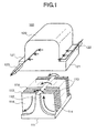
- Fig. 1 attached herewith shows the structure of a cooling jacket according to an embodiment of the present invention through the exploded perspective view thereof.
- This cooling jacket builds up a part of a so-called liquid cooling system together with a radiator, a driving pump, and a tank, etc., though not shown herein, within an electronic apparatus including the heat-generating element (for example, a CPU, etc.) inside a housing, such as, a desk-top type personal computer, a server, a notebook-type personal computer, etc., for example.
- the heat-generating element for example, a CPU, etc.
- those constituent parts are connected through metal tubes or the like, and in the inside thereof is enclosed a liquid refrigerant or coolant, such as, water and/or ethylene glycol, for example.
- the cooling jacket 100 has a base portion 110, which is made of a metal, such as, copper or aluminum, etc., for example, being superior in the heat conductivity, and a cover portion 120 for covering the base portion 110, surrounding the periphery thereof. Further, this base portion 110 builds up a heat-transfer surface 111 on the lower surface thereof, to be in contact with a surface of the heat-generating element, such as the CPU mentioned above, through a heat-conductive grease or paste or the like.
- This base portion 110 includes a solid (or an inside) portion having summit portions 112 at the central portion thereof, and building up a plural number of wall portions 113, extending into directions perpendicular to the heat-transfer surface 111 and also perpendicular to the summit portions 112. And, as is apparent from the figure, between those plural numbers of wall portions 113 are defined flow passages 114, each having a sector or a fan-like shape, approximately, in a large number thereof, while being piled up in the direction of the summit portion 112.
- the cover portion 120 onto the base portion 110 will be attached the cover portion 120, which is shaped, approximately, into a box-like outer configuration, so that it surrounds the periphery of the base portion 110 from the upper portion thereof. Further, at portions of the cover portion 120 (in front and back of a lower guide portion 121) are attached an inlet pipe 122 for introducing the liquid coolant and an outlet pipe 123 for discharging the coolant to the outside. Further, the cover portion 120 is attached onto the base portion 110 in a liquid-tight manner. For this reason, the liquid coolant running therein from the inlet pipe 122, as is shown by arrows in Fig.
- the heat-transfer surface 111 of the base portion 110 is in contact with an LSI chip 300 being the heat-generating body.
- a heat-conductive grease 150 or paste or the like having a superior heat-conductivity is provided there between for thermal connection. Therefore, heat generated from this heat-generating body 300 can diffuse, not only in the horizontal direction along the heat-transfer surface 111 of the base portion 110, but also in the direction towards the summit portion 112 of the base portion 110 (i.e., the vertical direction), too (see arrows with broken lines in the Fig. 2).
- the solid portion (i.e., the hatched portion) of the base portion is extended or elongated with respect to the heat-transfer surface 111, i.e., into the horizontal direction and also the vertical direction from the center of the heat-transfer surface, and further that the width thereof is gradually reducing with increasing distance from the center of the respective heat-transfer surfaces.
- the width of the respective solid portions becomes linearly smaller with increasing distance from the heat-transfer surface (such that the flow passage 114 is of about triangular shape), or being of constant width without change (such that the flow passage is of rectangular shape)), and also in such cases there can be obtained a similar effect as that mentioned above.
- Fig. 3 shows the structure of the cooling jacket according to another embodiment of the present invention.
- the inlet pipe 122 is attached on an upper portion of the cover portion 120, and the liquid coolant flows from the summit portion 112 of the base portion 110 into the fan-like shaped flow passages 114, which are made up on both sides thereof.
- the base portion 110 achieves the similar function because of its structure, i.e., diffusing the heat from the heat-generating body 300, which is disposed on the heat-transfer surface in contact therewith, isotropically. Therefore, it is possible to lower the heat resistance within the base portion 110, thereby enabling to increase the efficiency of the cooling jacket 100 considerably. It is further possible to reverse the flow direction of the liquid coolant so that it flows from the lower portions on both sides of the cover portion 120 to the upper portion, and a similar effect can be achieved.
- the solid portion (i.e., the hatched portion) of the base portion is preferably elongated with respect to the heat-transfer surface 111, i.e., in the horizontal direction and also the vertical direction from the center of the heat-transfer surface, and further, the width thereof becomes gradually smaller with increasing distance from the center of the respective heat-transfer surfaces (i.e., the fan-like flow passages).
- the configuration may be more simplified (for example, the width of the respective solid portions is becoming linearly smaller with increasing distance from the heat-transfer surface, or the width remains constant without change), and there can be obtained a similar effect as in the cases explained above.
Landscapes
- Engineering & Computer Science (AREA)
- Theoretical Computer Science (AREA)
- Human Computer Interaction (AREA)
- Physics & Mathematics (AREA)
- General Engineering & Computer Science (AREA)
- General Physics & Mathematics (AREA)
- Cooling Or The Like Of Semiconductors Or Solid State Devices (AREA)
- Cooling Or The Like Of Electrical Apparatus (AREA)
Applications Claiming Priority (1)
| Application Number | Priority Date | Filing Date | Title |
|---|---|---|---|
| JP2005105844A JP4551261B2 (ja) | 2005-04-01 | 2005-04-01 | 冷却ジャケット |
Publications (2)
| Publication Number | Publication Date |
|---|---|
| EP1708263A1 true EP1708263A1 (fr) | 2006-10-04 |
| EP1708263B1 EP1708263B1 (fr) | 2010-09-29 |
Family
ID=36588716
Family Applications (1)
| Application Number | Title | Priority Date | Filing Date |
|---|---|---|---|
| EP06007046A Expired - Lifetime EP1708263B1 (fr) | 2005-04-01 | 2006-04-03 | Carter de refroidissement |
Country Status (7)
| Country | Link |
|---|---|
| US (1) | US7721788B2 (fr) |
| EP (1) | EP1708263B1 (fr) |
| JP (1) | JP4551261B2 (fr) |
| KR (1) | KR100817267B1 (fr) |
| CN (1) | CN100394352C (fr) |
| DE (1) | DE602006017136D1 (fr) |
| TW (1) | TW200638183A (fr) |
Families Citing this family (16)
| Publication number | Priority date | Publication date | Assignee | Title |
|---|---|---|---|---|
| US7256998B2 (en) * | 2005-04-25 | 2007-08-14 | Giga-Byte Technology Co., Ltd. | Heat-dissipating structure with air-guiding device |
| JP4876975B2 (ja) * | 2007-03-02 | 2012-02-15 | 株式会社日立製作所 | 電子機器用の冷却装置および受熱部材 |
| US8291965B2 (en) * | 2007-03-27 | 2012-10-23 | Adc Telecommunications, Inc. | Heat sink with angled fins |
| US7497249B2 (en) * | 2007-03-30 | 2009-03-03 | Delphi Technologies, Inc. | Thermosiphon for laptop computer |
| US7884468B2 (en) * | 2007-07-30 | 2011-02-08 | GM Global Technology Operations LLC | Cooling systems for power semiconductor devices |
| USD684544S1 (en) | 2011-05-13 | 2013-06-18 | Fuji Electric Co., Ltd. | Cooling jacket for semiconductor device |
| JPWO2012157247A1 (ja) | 2011-05-16 | 2014-07-31 | 富士電機株式会社 | 半導体モジュール用冷却器 |
| CN104750207A (zh) * | 2013-12-30 | 2015-07-01 | 鸿富锦精密工业(武汉)有限公司 | 散热模组 |
| US10462939B2 (en) * | 2015-01-22 | 2019-10-29 | Mitsubishi Electric Corporation | Semiconductor device |
| TWI624640B (zh) * | 2017-01-25 | 2018-05-21 | 雙鴻科技股份有限公司 | 液冷式散熱裝置 |
| CN110531571B (zh) * | 2018-05-24 | 2021-08-24 | 中强光电股份有限公司 | 液冷式散热器 |
| CN110543069A (zh) * | 2018-05-28 | 2019-12-06 | 中强光电股份有限公司 | 液冷式散热器 |
| JP7022660B2 (ja) * | 2018-06-28 | 2022-02-18 | 三菱重工業株式会社 | 放熱装置及び半導体素子 |
| JP6640401B1 (ja) | 2019-04-18 | 2020-02-05 | 古河電気工業株式会社 | ヒートシンク |
| DE112019007686B4 (de) | 2019-09-04 | 2023-08-03 | Mitsubishi Electric Corporation | Kühlkörper und halbleitermodul |
| CN117334653A (zh) * | 2023-10-08 | 2024-01-02 | 蔚来汽车科技(安徽)有限公司 | 散热装置、电子设备和车辆 |
Citations (6)
| Publication number | Priority date | Publication date | Assignee | Title |
|---|---|---|---|---|
| US4558395A (en) * | 1983-04-27 | 1985-12-10 | Hitachi, Ltd. | Cooling module for integrated circuit chips |
| US5132780A (en) * | 1988-01-07 | 1992-07-21 | Prime Computer, Inc. | Heat sink apparatus with an air deflection member |
| EP0641023A1 (fr) * | 1993-08-25 | 1995-03-01 | International Business Machines Corporation | Module convertible pour le refroidissement air ou eau de composants électroniques |
| EP1175135A1 (fr) * | 2000-07-21 | 2002-01-23 | Mitsubishi Materials Corporation | Dissipateur de chaleur à refroidissement par liquide et sa méthode de fabrication |
| US20020070006A1 (en) * | 2000-12-07 | 2002-06-13 | Mok Lawrence Shungwei | Increased efficiency in liquid and gaseous planar device cooling technology |
| US20030029601A1 (en) * | 2001-08-07 | 2003-02-13 | International Business Machines Corporation | Heat sink for convection cooling in horizontal applications |
Family Cites Families (18)
| Publication number | Priority date | Publication date | Assignee | Title |
|---|---|---|---|---|
| JPH0732221B2 (ja) * | 1988-10-06 | 1995-04-10 | 日本電気株式会社 | 集積回路の冷却構造 |
| US5006924A (en) * | 1989-12-29 | 1991-04-09 | International Business Machines Corporation | Heat sink for utilization with high density integrated circuit substrates |
| JPH0751404Y2 (ja) * | 1990-01-26 | 1995-11-22 | 池田物産株式会社 | 内装材の接合構造 |
| JPH042156A (ja) * | 1990-04-19 | 1992-01-07 | Fuji Electric Co Ltd | 電力用半導体装置 |
| US5125451A (en) * | 1991-04-02 | 1992-06-30 | Microunity Systems Engineering, Inc. | Heat exchanger for solid-state electronic devices |
| US5239200A (en) * | 1991-08-21 | 1993-08-24 | International Business Machines Corporation | Apparatus for cooling integrated circuit chips |
| JPH06266474A (ja) | 1993-03-17 | 1994-09-22 | Hitachi Ltd | 電子機器装置及びラップトップ型電子機器装置 |
| JPH07115156A (ja) * | 1993-10-19 | 1995-05-02 | Nec Corp | 集積回路の冷却構造 |
| JP3385482B2 (ja) | 1993-11-15 | 2003-03-10 | 株式会社日立製作所 | 電子機器 |
| JP2000101008A (ja) * | 1998-09-21 | 2000-04-07 | Mitsubishi Electric Corp | ヒートシンク及びその製造方法 |
| JP3982180B2 (ja) * | 2000-02-16 | 2007-09-26 | 株式会社日立製作所 | 電力変換装置 |
| US6367543B1 (en) * | 2000-12-11 | 2002-04-09 | Thermal Corp. | Liquid-cooled heat sink with thermal jacket |
| JP2002232174A (ja) * | 2001-02-06 | 2002-08-16 | Hitachi Ltd | 電子装置 |
| JP2003324173A (ja) * | 2002-05-02 | 2003-11-14 | Nissan Motor Co Ltd | 半導体素子の冷却装置 |
| JP2004200333A (ja) * | 2002-12-18 | 2004-07-15 | Hitachi Ltd | 水冷型電力用半導体モジュールの実装構造 |
| US20040182544A1 (en) * | 2002-12-27 | 2004-09-23 | Lee Hsieh Kun | Cooling device utilizing liquid coolant |
| JP2004295718A (ja) * | 2003-03-28 | 2004-10-21 | Hitachi Ltd | 情報処理装置の液例システム |
| JP4140495B2 (ja) * | 2003-09-25 | 2008-08-27 | 株式会社日立製作所 | 冷却モジュール |
-
2005
- 2005-04-01 JP JP2005105844A patent/JP4551261B2/ja not_active Expired - Fee Related
-
2006
- 2006-03-06 TW TW095107454A patent/TW200638183A/zh unknown
- 2006-03-31 US US11/393,780 patent/US7721788B2/en not_active Expired - Fee Related
- 2006-03-31 KR KR1020060029422A patent/KR100817267B1/ko not_active Expired - Fee Related
- 2006-03-31 CN CNB2006100710345A patent/CN100394352C/zh not_active Expired - Fee Related
- 2006-04-03 DE DE602006017136T patent/DE602006017136D1/de not_active Expired - Lifetime
- 2006-04-03 EP EP06007046A patent/EP1708263B1/fr not_active Expired - Lifetime
Patent Citations (6)
| Publication number | Priority date | Publication date | Assignee | Title |
|---|---|---|---|---|
| US4558395A (en) * | 1983-04-27 | 1985-12-10 | Hitachi, Ltd. | Cooling module for integrated circuit chips |
| US5132780A (en) * | 1988-01-07 | 1992-07-21 | Prime Computer, Inc. | Heat sink apparatus with an air deflection member |
| EP0641023A1 (fr) * | 1993-08-25 | 1995-03-01 | International Business Machines Corporation | Module convertible pour le refroidissement air ou eau de composants électroniques |
| EP1175135A1 (fr) * | 2000-07-21 | 2002-01-23 | Mitsubishi Materials Corporation | Dissipateur de chaleur à refroidissement par liquide et sa méthode de fabrication |
| US20020070006A1 (en) * | 2000-12-07 | 2002-06-13 | Mok Lawrence Shungwei | Increased efficiency in liquid and gaseous planar device cooling technology |
| US20030029601A1 (en) * | 2001-08-07 | 2003-02-13 | International Business Machines Corporation | Heat sink for convection cooling in horizontal applications |
Also Published As
| Publication number | Publication date |
|---|---|
| CN1841265A (zh) | 2006-10-04 |
| US20060219387A1 (en) | 2006-10-05 |
| JP2006287017A (ja) | 2006-10-19 |
| DE602006017136D1 (de) | 2010-11-11 |
| KR20060105637A (ko) | 2006-10-11 |
| KR100817267B1 (ko) | 2008-03-27 |
| EP1708263B1 (fr) | 2010-09-29 |
| US7721788B2 (en) | 2010-05-25 |
| CN100394352C (zh) | 2008-06-11 |
| TW200638183A (en) | 2006-11-01 |
| JP4551261B2 (ja) | 2010-09-22 |
Similar Documents
| Publication | Publication Date | Title |
|---|---|---|
| JP3594900B2 (ja) | ディスプレイ装置一体型コンピュータ | |
| US7516777B2 (en) | Cooling jacket | |
| US6833992B2 (en) | Electronic apparatus having a plurality of radiators in which liquid coolant flows | |
| US7273089B2 (en) | Electronic apparatus having a heat-radiating unit for radiating heat of heat-generating components | |
| JP4140495B2 (ja) | 冷却モジュール | |
| EP1708263B1 (fr) | Carter de refroidissement | |
| US6639797B2 (en) | Computer having cooling device | |
| US20040042174A1 (en) | Electronic apparatus | |
| JP2001077256A (ja) | 冷却ユニット | |
| JP2003152376A (ja) | 電子装置 | |
| JP3068892U (ja) | Cpu放熱装置 | |
| JPH11243289A (ja) | 電子機器 | |
| JP4682858B2 (ja) | 電子機器用の冷却装置 | |
| JP2003022148A (ja) | ノート型パソコンの液冷システム | |
| CN201039650Y (zh) | 视讯控制卡的散热装置 | |
| CN100592850C (zh) | 热管散热装置 | |
| JP2004094961A (ja) | ディスプレイ装置一体型コンピュータ及びこれに用いる冷却モジュール | |
| JP2006235914A (ja) | 液冷システムと、当該システムを備えた小型電子装置 | |
| JP3839426B2 (ja) | ディスプレイ装置一体型コンピュータにおける冷却モジュール | |
| JP4332359B2 (ja) | コンピュータ冷却装置 | |
| JP2005317033A (ja) | ディスプレイ装置一体型コンピュータ及びこれに用いる冷却モジュール | |
| JP2003258474A (ja) | 電子機器 |
Legal Events
| Date | Code | Title | Description |
|---|---|---|---|
| PUAI | Public reference made under article 153(3) epc to a published international application that has entered the european phase |
Free format text: ORIGINAL CODE: 0009012 |
|
| AK | Designated contracting states |
Kind code of ref document: A1 Designated state(s): AT BE BG CH CY CZ DE DK EE ES FI FR GB GR HU IE IS IT LI LT LU LV MC NL PL PT RO SE SI SK TR |
|
| AX | Request for extension of the european patent |
Extension state: AL BA HR MK YU |
|
| 17P | Request for examination filed |
Effective date: 20070404 |
|
| AKX | Designation fees paid |
Designated state(s): DE FR GB |
|
| 17Q | First examination report despatched |
Effective date: 20070530 |
|
| GRAP | Despatch of communication of intention to grant a patent |
Free format text: ORIGINAL CODE: EPIDOSNIGR1 |
|
| GRAC | Information related to communication of intention to grant a patent modified |
Free format text: ORIGINAL CODE: EPIDOSCIGR1 |
|
| GRAS | Grant fee paid |
Free format text: ORIGINAL CODE: EPIDOSNIGR3 |
|
| RIN1 | Information on inventor provided before grant (corrected) |
Inventor name: ATARASHI, TAKAYUKIC/O HITACHI, LTD. Inventor name: NAKANISHI, MASATOC/O HITACHI, LTD. |
|
| RAP1 | Party data changed (applicant data changed or rights of an application transferred) |
Owner name: HITACHI, LTD. |
|
| GRAA | (expected) grant |
Free format text: ORIGINAL CODE: 0009210 |
|
| AK | Designated contracting states |
Kind code of ref document: B1 Designated state(s): DE FR GB |
|
| REG | Reference to a national code |
Ref country code: GB Ref legal event code: FG4D |
|
| REF | Corresponds to: |
Ref document number: 602006017136 Country of ref document: DE Date of ref document: 20101111 Kind code of ref document: P |
|
| PGFP | Annual fee paid to national office [announced via postgrant information from national office to epo] |
Ref country code: GB Payment date: 20110318 Year of fee payment: 6 Ref country code: FR Payment date: 20110511 Year of fee payment: 6 |
|
| PLBE | No opposition filed within time limit |
Free format text: ORIGINAL CODE: 0009261 |
|
| STAA | Information on the status of an ep patent application or granted ep patent |
Free format text: STATUS: NO OPPOSITION FILED WITHIN TIME LIMIT |
|
| REG | Reference to a national code |
Ref country code: DE Ref legal event code: R097 Ref document number: 602006017136 Country of ref document: DE Effective date: 20110630 |
|
| PGFP | Annual fee paid to national office [announced via postgrant information from national office to epo] |
Ref country code: DE Payment date: 20120430 Year of fee payment: 7 |
|
| GBPC | Gb: european patent ceased through non-payment of renewal fee |
Effective date: 20120403 |
|
| REG | Reference to a national code |
Ref country code: FR Ref legal event code: ST Effective date: 20121228 |
|
| PG25 | Lapsed in a contracting state [announced via postgrant information from national office to epo] |
Ref country code: GB Free format text: LAPSE BECAUSE OF NON-PAYMENT OF DUE FEES Effective date: 20120403 |
|
| PG25 | Lapsed in a contracting state [announced via postgrant information from national office to epo] |
Ref country code: FR Free format text: LAPSE BECAUSE OF NON-PAYMENT OF DUE FEES Effective date: 20120430 |
|
| PG25 | Lapsed in a contracting state [announced via postgrant information from national office to epo] |
Ref country code: DE Free format text: LAPSE BECAUSE OF NON-PAYMENT OF DUE FEES Effective date: 20131101 |
|
| REG | Reference to a national code |
Ref country code: DE Ref legal event code: R119 Ref document number: 602006017136 Country of ref document: DE Effective date: 20131101 |