EP1735568B1 - Dispositifs, systemes et procedes de deplacement d'air en colonne - Google Patents
Dispositifs, systemes et procedes de deplacement d'air en colonne Download PDFInfo
- Publication number
- EP1735568B1 EP1735568B1 EP05714125.1A EP05714125A EP1735568B1 EP 1735568 B1 EP1735568 B1 EP 1735568B1 EP 05714125 A EP05714125 A EP 05714125A EP 1735568 B1 EP1735568 B1 EP 1735568B1
- Authority
- EP
- European Patent Office
- Prior art keywords
- air
- housing
- ceiling
- air flow
- set forth
- Prior art date
- Legal status (The legal status is an assumption and is not a legal conclusion. Google has not performed a legal analysis and makes no representation as to the accuracy of the status listed.)
- Expired - Lifetime
Links
- 238000000034 method Methods 0.000 title claims description 6
- 238000011144 upstream manufacturing Methods 0.000 claims description 32
- 239000006185 dispersion Substances 0.000 claims description 10
- 230000007423 decrease Effects 0.000 claims description 5
- XLYOFNOQVPJJNP-UHFFFAOYSA-N water Substances O XLYOFNOQVPJJNP-UHFFFAOYSA-N 0.000 claims description 4
- 230000006835 compression Effects 0.000 claims description 2
- 238000007906 compression Methods 0.000 claims description 2
- 230000013011 mating Effects 0.000 claims description 2
- 230000003068 static effect Effects 0.000 claims description 2
- 238000007599 discharging Methods 0.000 claims 1
- 239000003595 mist Substances 0.000 claims 1
- 238000013517 stratification Methods 0.000 description 6
- 238000004378 air conditioning Methods 0.000 description 3
- 238000010438 heat treatment Methods 0.000 description 3
- 239000002981 blocking agent Substances 0.000 description 1
- 238000006243 chemical reaction Methods 0.000 description 1
- 238000010276 construction Methods 0.000 description 1
- 230000001419 dependent effect Effects 0.000 description 1
- 239000000645 desinfectant Substances 0.000 description 1
- 238000009792 diffusion process Methods 0.000 description 1
- 230000008020 evaporation Effects 0.000 description 1
- 238000001704 evaporation Methods 0.000 description 1
- 230000009970 fire resistant effect Effects 0.000 description 1
- 239000012530 fluid Substances 0.000 description 1
- 239000003205 fragrance Substances 0.000 description 1
- 239000002991 molded plastic Substances 0.000 description 1
- 230000000149 penetrating effect Effects 0.000 description 1
- 230000002093 peripheral effect Effects 0.000 description 1
- 239000007921 spray Substances 0.000 description 1
- 238000009423 ventilation Methods 0.000 description 1
Images






Classifications
-
- F—MECHANICAL ENGINEERING; LIGHTING; HEATING; WEAPONS; BLASTING
- F24—HEATING; RANGES; VENTILATING
- F24F—AIR-CONDITIONING; AIR-HUMIDIFICATION; VENTILATION; USE OF AIR CURRENTS FOR SCREENING
- F24F7/00—Ventilation
- F24F7/007—Ventilation with forced flow
-
- F—MECHANICAL ENGINEERING; LIGHTING; HEATING; WEAPONS; BLASTING
- F04—POSITIVE - DISPLACEMENT MACHINES FOR LIQUIDS; PUMPS FOR LIQUIDS OR ELASTIC FLUIDS
- F04D—NON-POSITIVE-DISPLACEMENT PUMPS
- F04D25/00—Pumping installations or systems
- F04D25/02—Units comprising pumps and their driving means
- F04D25/08—Units comprising pumps and their driving means the working fluid being air, e.g. for ventilation
- F04D25/088—Ceiling fans
-
- F—MECHANICAL ENGINEERING; LIGHTING; HEATING; WEAPONS; BLASTING
- F04—POSITIVE - DISPLACEMENT MACHINES FOR LIQUIDS; PUMPS FOR LIQUIDS OR ELASTIC FLUIDS
- F04D—NON-POSITIVE-DISPLACEMENT PUMPS
- F04D25/00—Pumping installations or systems
- F04D25/02—Units comprising pumps and their driving means
- F04D25/08—Units comprising pumps and their driving means the working fluid being air, e.g. for ventilation
- F04D25/12—Units comprising pumps and their driving means the working fluid being air, e.g. for ventilation the unit being adapted for mounting in apertures
-
- F—MECHANICAL ENGINEERING; LIGHTING; HEATING; WEAPONS; BLASTING
- F04—POSITIVE - DISPLACEMENT MACHINES FOR LIQUIDS; PUMPS FOR LIQUIDS OR ELASTIC FLUIDS
- F04D—NON-POSITIVE-DISPLACEMENT PUMPS
- F04D29/00—Details, component parts, or accessories
- F04D29/40—Casings; Connections of working fluid
- F04D29/52—Casings; Connections of working fluid for axial pumps
- F04D29/54—Fluid-guiding means, e.g. diffusers
- F04D29/541—Specially adapted for elastic fluid pumps
- F04D29/542—Bladed diffusers
-
- F—MECHANICAL ENGINEERING; LIGHTING; HEATING; WEAPONS; BLASTING
- F04—POSITIVE - DISPLACEMENT MACHINES FOR LIQUIDS; PUMPS FOR LIQUIDS OR ELASTIC FLUIDS
- F04D—NON-POSITIVE-DISPLACEMENT PUMPS
- F04D29/00—Details, component parts, or accessories
- F04D29/40—Casings; Connections of working fluid
- F04D29/52—Casings; Connections of working fluid for axial pumps
- F04D29/54—Fluid-guiding means, e.g. diffusers
- F04D29/541—Specially adapted for elastic fluid pumps
- F04D29/545—Ducts
- F04D29/547—Ducts having a special shape in order to influence fluid flow
-
- F—MECHANICAL ENGINEERING; LIGHTING; HEATING; WEAPONS; BLASTING
- F04—POSITIVE - DISPLACEMENT MACHINES FOR LIQUIDS; PUMPS FOR LIQUIDS OR ELASTIC FLUIDS
- F04D—NON-POSITIVE-DISPLACEMENT PUMPS
- F04D29/00—Details, component parts, or accessories
- F04D29/60—Mounting; Assembling; Disassembling
- F04D29/601—Mounting; Assembling; Disassembling specially adapted for elastic fluid pumps
-
- F—MECHANICAL ENGINEERING; LIGHTING; HEATING; WEAPONS; BLASTING
- F24—HEATING; RANGES; VENTILATING
- F24F—AIR-CONDITIONING; AIR-HUMIDIFICATION; VENTILATION; USE OF AIR CURRENTS FOR SCREENING
- F24F13/00—Details common to, or for air-conditioning, air-humidification, ventilation or use of air currents for screening
- F24F13/08—Air-flow control members, e.g. louvres, grilles, flaps or guide plates
-
- F—MECHANICAL ENGINEERING; LIGHTING; HEATING; WEAPONS; BLASTING
- F24—HEATING; RANGES; VENTILATING
- F24F—AIR-CONDITIONING; AIR-HUMIDIFICATION; VENTILATION; USE OF AIR CURRENTS FOR SCREENING
- F24F7/00—Ventilation
- F24F7/04—Ventilation with ducting systems, e.g. by double walls; with natural circulation
- F24F7/06—Ventilation with ducting systems, e.g. by double walls; with natural circulation with forced air circulation, e.g. by fan positioning of a ventilator in or against a conduit
- F24F7/065—Ventilation with ducting systems, e.g. by double walls; with natural circulation with forced air circulation, e.g. by fan positioning of a ventilator in or against a conduit fan combined with single duct; mounting arrangements of a fan in a duct
-
- F—MECHANICAL ENGINEERING; LIGHTING; HEATING; WEAPONS; BLASTING
- F24—HEATING; RANGES; VENTILATING
- F24F—AIR-CONDITIONING; AIR-HUMIDIFICATION; VENTILATION; USE OF AIR CURRENTS FOR SCREENING
- F24F2110/00—Control inputs relating to air properties
- F24F2110/50—Air quality properties
Definitions
- the present invention relates to heating, ventilating and air conditioning air spaces, and more particularly to a structure and method for moving air in a columnar pattern with minimal lateral dispersion that are particularly suitable for penetrating air spaces and air temperature de-stratification.
- Ceiling fans are relatively large rotary fans, with a plurality of blades, mounted near the ceiling.
- the blades of a ceiling fan have a flat or airfoil shape.
- the blades have a lift component that pushes air upwards or downwards, depending on the direction of rotation, and a drag component that pushes the air tangentially.
- the drag component causes tangential or centrifugal flow so that the air being pushed diverges or spreads out.
- Conventional ceiling fans are generally ineffective as an air de-stratification device in relatively high ceiling rooms because the air pushed by conventional ceiling fans is not maintained in a columnar pattern from the ceiling to the floor, and often disperses or diffuses well above the floor.
- Another proposed solution to air temperature stratification is a fan connected to a vertical tube that extends substantially from the ceiling to the floor.
- the fan may be mounted near the ceiling, near the floor or in between. This type of device may push cooler air up from the floor to the ceiling or warmer air down from the ceiling to the floor.
- Such devices when located away from the walls in an open space in a building, interfere with floorspace use and are not aesthetically pleasing. When confined to locations only along the walls of an open space, such devices may not effectively circulate air near the center of the open space. Examples of fans connected to vertical tubes are disclosed in U.S. Patent No. 3,827,342 to Hughes , and U.S. Patent No. 3,973,479 to Whiteley .
- U.S. Patents No. 4,473,000 and 4,662,912 to Perkins disclose a device having a housing, with a rotating impeller having blades in the top of the housing and a plurality of interspersed small and large, vertically extending, radial stationary vanes spaced below the impeller in the housing.
- the device disclosed by Perkins is intended to direct the air in a more clearly defined pattern and reduce dispersion.
- Perkins does not disclose the importance of a specific, relatively small gap between the impeller blades and the stationary vanes, and the device illustrated creates a vortex and turbulence due to a large gap and centrifugal air flow bouncing off the inner walls of the housing between the blades and vanes.
- Perkins also discloses a tapering vane section. The tapering vane section increases velocity of the exiting air stream.
- GB 981188 discloses an air moving device located within a piping system for ensuring the flow of air within the piping system, comprising an impeller and a rectifier downstream of the impeller.
- a device with a rotary fan that minimizes the rotary component of the air flow while maximizing the axial air flow quantity and velocity can provide a column of air that flows from a high ceiling to a floor in a columnar pattern with minimal lateral dispersion that does not require a physical transporting tube.
- Such a device should reduce the energy loss by minimizing the rotary component of the air flow, and therefore minimizes turbulence.
- Such a device should minimize back pressure, since a pressure drop at the outlet of the device will cause expansion, velocity loss and lateral dispersion.
- the device should have minimum noise and low electric power requirements.
- the present invention provides a structure comprising a room, said room comprising a ceiling, a floor and opposed side walls and defining an airspace, and an air moving device positioned within said room mounted to the ceiling, said air moving device being without a vertical tube that extends substantially from the ceiling to the floor and comprising:
- the present invention also provides a method of moving air in a room comprising a ceiling, a floor and opposed side walls, which define an air space, comprising the steps of:
- the structure and method are particularly suitable for high efficiency, low power usage, air temperature de-stratification, and to improve air quality and circulation.
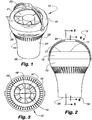
- an air moving device 12 having an elongated outer housing 13, an electric rotary fan 14 in the housing for producing air flow in the housing and a plurality of longitudinally extending, outer radial vanes 15 and an inner housing hub 16 opposite the vanes in the housing downstream of the fan for directing air flow in the housing.
- the housing 13 has a circular cross section, and an open first end 17 and an open second end 18 spaced from the first end 17.
- a detachable, axially outwardly convex cowling 19 forms the first end 17 and provides an air inlet 21 with a diameter slightly smaller than the outer diameter of the cowling 19.
- the housing 13 has a first section 25 extending from the cowling 19 to an interior shelf 26.
- a generally C-shaped hanger 23 mounts at opposite ends 24 to opposite sides of the housing 13 at the upper end of the first section 25, for mounting the air moving device 12 to a support.
- the first section 25, when viewed from the side, has a curved, slightly radially outwardly convex shape that conforms to the curvature of the cowling 19.
- the shelf 26 extends radially inwardly to join with the upstream end of a second section 27.
- the second section 27 tapers inwardly and extends axially from the shelf 26 to the second end 18 along a smooth curve that goes from radially outwardly convex near the shelf 26 to radially outwardly concave near the second end 18.
- the second end 18 forms an air outlet 28 that has a smaller diameter than the air inlet 21.
- a plurality of circumferentially spaced external fins 29 extend from the shelf 26 to the second section 27 to provide the appearance of a smooth curve from the air inlet 21 to the air outlet 28 when the housing 13 is viewed from the side.
- the fan 14 includes an impeller 31 having a cylindrical, inner impeller hub 32, with an electric motor 34 therein, and a plurality of rigidly mounted, circumferentially spaced blades 33 extending radially from the impeller hub 32.
- the impeller 31 has three equally spaced blades 33 and rotates about an axis in a counter-clockwise direction when viewed from above.
- Each blade 33 in side view, extends from an upstream edge 35, downwardly and leftwardly to a downstream edge 36 with each blade 33 being slightly concave, in an airfoil or wing shape, downwardly to propel air rightwardly as shown by the arrow.
- Each blade 33 then inclines at a selected angle to the axis of rotation of the impeller.
- Each blade 33 shown extends axially and radially toward the outlet or second end 18 to direct air axially with a rotary component. If the motor 34 runs in the opposite direction, the incline of the blades 33 would be reversed.
- the fan 14 includes a stationary cylindrical mounting ring 38 that extends around the blades 33, with the impeller hub 32 being rotably mounted relative to the mounting ring 38.
- the mounting ring 38 has spaced, protruding upstream and downstream rims 40 and 41.
- the fan 14 mounts in the housing 13 between the cowling 19 and the shelf 26.
- Each of the vanes 15 is identical and includes upstream portion 43 and a downstream portion 44.
- the upstream portion 43 is carried in a stator 46.
- the stator 46 has a cylindrical stator hub 47 with a diameter substantially equal to the diameter of the impeller hub 32.
- the upstream portions 43 of the vanes 15 are mounted in a circumferentially spaced arrangement around the stator hub 47, and extend longitudinally along and radially from the stator hub 47.
- Each upstream portion 43 has an upstream end 48 and a downstream end 49.
- a support body 50 includes a cylindrical stator ring 52 that extends around the upstream portions 43 and connects to the outer ends of the upstream portions 43 of the vanes 15 near the upstream ends 48.
- the support body 50 also includes a protruding stator rim 53 that is substantially planar with the upstream ends 48 of the upstream portions 43 of the vanes 15, and that connects to the stator ring 52 and extends radially outwardly therefrom.
- the housing 13 has an inner surface and the inner housing hub 16 has an outer surface concentric with a spaced from the housing inner surface to define an air flow passage through the housing.
- the inner housing hub 16 includes the fan hub 32, stator hub portion 47 and downstream hub portion 57, each having an outer surface and arranged end to end along the center of the housing and opposite and spaced from the housing inner surface to define the air flow passage.
- these outer surfaces shown are cylindrical and substantially the same diameter for a substantial portion of the passage and as the housing 13 converges the downstream hub portion 57 converges to generally follow the curvature of the inside surface of the housing.
- the stator 46 nests in and is separable from the housing 13 with the stator rim 53 between the shelf 26 of the housing 13 and the downstream rim 41 of the mounting ring 38 of the fan 14, and with a gap 55 having a selected size between the downstream edge 36 of the blades 33 of the impeller 31 and the upstream ends 49 of the upstream portions 43 of the vanes 15. If the gap 55 is too large, turbulence will be generated in the air flow between the impeller 31 and the vanes 15, reducing the velocity of the air flow. If the gap 55 is too small, fluid shear stress will generate noise.
- the size of the gap 55 is generally selected as no greater than a maximum selected dimension to avoid turbulence and no less than a selected minimum dimension to avoid noise, and more particularly selected as small as possible without generating noise.
- the selected size of the gap 55 is generally proportional to the diameter of the impeller 31 and may further be affected by the speed of the impeller 31.
- the maximum size of the gap 55 For an impeller 31 with a diameter of 8.5" (21.6 cm) at 1400 rpm, the maximum size of the gap 55 should be 1.25" (3.18 cm), and the minimum gap should be 0.2" (0.5 cm) but could be .020 (0.051 cm) for lower rpm's as the size of the gap is rpm dependent.
- the maximum size of the gap 55 should be less than one half the diameter of the impeller 31.
- each curved vane portion is inclined at an angle opposite the incline of the blade 33 that extends axially and radially inward toward the outlet or second end 28 to assist in converting the rotary component of the air flow into laminar and axial flow in the housing.
- Straight upstream portions 43A of the vanes 15 may also be used, as shown in Figure 7 , and other numbers of vanes 15 may be used. Further, if the motor 34 runs in the opposite direction, the incline of the curvature near the upstream ends 48 would be reversed.
- the downstream portions 44 of the vanes 15 attach at an inner end to a downstream inner housing hub portion 57, are circumferentially spaced and extend radially outwardly from the housing hub portion 57 to the housing 13.
- the housing hub portion 57 and the downstream portions 44 of the vanes 15 extend axially from the stator 46 to or near the air outlet 28.
- the housing hub portion 57 has a circular cross section, has a diameter substantially equal to the diameter of the stator housing hub portion 47 at the upstream end adjacent to the stator housing hub portion 47, and tapers downstream to a point 58 near the air outlet 28.
- This hub portion may be characterized as torpedo shaped.
- the number of the blades 33 may be 2, 3, 4, 5, 6, 7 or 8.
- the number of the vanes 15 may be 2, 3, 4, 5, 6, 7 or 8.
- the number of vanes 15 should be different from the number of blades 33. If the number of vanes 15 and blades 33 are the same, added noise is generated due to harmonics.
- the air moving device 12 discharges air at a high velocity in a generally axial flow having a columnar pattern with minimal lateral dispersion after exiting the air outlet 28.
- the cowling 19 extends along a curve toward the inside to reduce turbulence and noise for air flow entering the air inlet 21.
- the impeller hub 32, the stator hub 47 and the housing hub 57 form the inner housing hub 16.
- the taper of the housing hub 57 generally follows the taper of the housing 13 so that the cross sectional area for air flow decreases about 10% to 35% through the air moving device 12 to avoid back pressure and at the same time increase air flow velocity. In the embodiment shown the air flow decreases about 22%.
- the vanes 15 convert the rotary component of the air flow from the impeller 31 into laminar and axial air flow in the housing.
- the leftward curve of the upstream ends 48 of the upstream portions 43 of the vanes 15, in the illustrated embodiment, reduces the energy loss in the conversion of the rotary component of the air flow from the impeller 31 into laminar and axial air flow in the housing.
- the small gap 55 between the impeller 31 and vanes 15 prevents the generation of turbulence in the air flow in the gap 55.
- the taper of the housing 13 in combination with the taper of the housing hub 57 to the point 58 allows the air flow to exit the air outlet 28 in a continuous, uninterrupted columnar pattern with minimal dispersion, with no center hole or gap at a linear speed greater than would be imparted by a fan alone.
- the inside surface of the housing 13 is a substantially smooth uninterrupted surface to minimize turbulence and energy loss.
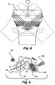
- the hanger 23 is mounted to rotate and lock relative to the housing 13, so that when the hanger 23 is attached to an overhead support such as ceiling, the air flow from the air moving device 12 may be directed vertically or aimed at any selected angle from the vertical as shown in Figure 8 .
- the first section 25 of the housing 13 includes mounting tabs 91 on opposite sides on the upper edge of the first section 25.
- Each mounting tab 91 includes a round, outwardly directed mounting face 92, and a housing aperture 93 that extends inwardly through the center of the mounting tab 91.
- a pair of outwardly projecting housing ridges 94 extend radially on the mounting face 92 on opposite sides of the housing aperture 93.
- Each end 24 of the hanger 23 has a round, inwardly facing hanger end face 96, similar in size to the mounting face 92 on the housing 13.
- a hanger end aperture 97 extends through the center of the hanger end face 96.
- Bolt 100 extends through the hanger end aperture 97 and threads into an internally threaded cylindrical insert 101, rigidly affixed in housing aperture 93.
- the angle of the housing 13 is chosen by selecting a pair of opposed grooves 97 on each hanger end 24 to receive the housing ridges 94.
- the pivotal arrangement enables the housing to move to a selected angle and is lockable at the selected angle to direct air flow at the selected angle.
- Figure 10 shows an air moving device 12 mounted to the ceiling 62 of a room 63 shown as being closed sided with opposed side walls. Warn air near the ceiling 62 is pulled into the air moving device 12. The warm air exits the air moving device 12 in a column 64 that extends to the floor 65. When the column 64 reaches the floor 65, the warm air from the ceiling pushes the colder air at the floor 65 outward towards the opposed side walls 66 and upward towards the ceiling 62. When the column 64 reaches the floor 65, the warm air from the ceiling will also transfer heat into the floor 65, so that heat is stored in the floor 65. The stored heat is released when the ceiling is cooler than the floor. The heat may also be stored in articles on the floor and earth under the floor.
- the air moving device 12 destratifies the air in a room 63 without requiring the imperforate physical tube of many prior known devices.
- the air moving device 12 destratifies the air in a room 63 with the warmer air from the ceiling 62 minimally dispersing before reaching the floor 65, unlike many other prior known devices.
- the air moving device 12 will also remove dead air anywhere in the room.
- an air moving device 12 is fitted with an inlet grill 68 and an electric connector 69 for attachment to a light can 70 with a light bulb socket 71 at the upper end.
- the inlet grill 68 includes a plurality of circumferentially spaced grill fins 72 that attach to the first end 17 of the housing 13.
- the grill fins 72 are separated by air intake slots 73, and extend axially outwardly from the first end 17 and curve radially inwardly and are integral with a flat circular mounting plate 74 that is substantially parallel with the first end 17.
- the electrical connector 69 has a tube 76 that is integral at one end with the center of the mounting plate 74 and extends axially therefrom, and a light bulb type, right hand thread externally threaded male end 77 attached to the other end of the shaft 78.
- Grill 68, plate 74 and tube 76 are shown as made of a one piece construction.
- Plate 74 has holes that received screws 83 or like fasteners to fasten plate 74 to ceiling 62.
- the shaft 78 telescopes in the tube 76.
- the tube 76 has a pair of opposed keyways 76A that receive keys 78A on the shaft 78 which allow axial sliding movement of the shaft 78 in the tube 76.
- a compression spring 75 fits in the tube and bears against the bottom of shaft 78 and top of plate 74.
- the shaft 78 has a selected length relative to the length of the can 70 such that when the air moving device 12 is mounted in a can 70 in a ceiling 62, the threaded male end 77 engages the socket 71 before the mounting plate 74 contacts the ceiling 62 and when the threaded male end 77 is screwed into the socket 71, the mounting plate 74 bears against the ceiling 62.
- the spring 75 is compressed between plate 74 and shaft 78. Screws 83 fasten the plate to the ceiling 62. Since the light can 70 may be open to air above the ceiling 62, the mounting plate 74 is preferably sized to cover the open lower end of the can 70, so that only air from below the ceiling 62 is drawn into -the air moving device 12.
- the air moving device 12 fitted with the inlet grill 68 and the electrical connector 69 can also be used with a ceiling light socket.
- the air moving device 12 may include an intake grill 79 for preventing objects from entering the impeller 31, as shown in Figure 12 .
- the intake grill 79 shown has a substantially hemispherical shape, and includes a plurality of circumferentially spaced grill fins 80 separated by intake slots 81.
- the grill fins 80 extend axially outwardly and curve radially inwardly from the first end 17 of the housing 13 to a central point 82 spaced from the first end 17.
- Other shapes of intake grills are suitable for the present invention.
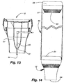
- Figure 13 shows an air moving device 12 with a misting nozzle 84.
- the nozzle 84 extends through the point 58 of the housing hub 57 to spray water into the column of air exiting the air outlet 28 to cool the air through evaporation.
- the media exiting the nozzle 84 and being supplied through tube 85 can have other purposes such as a disinfectant or a fragrance or a blocking agent for distinctive needs.
- the nozzle 84 connects to a water line 85, in the housing hub 59 that connects to a water source .(not shown) .
- Figure 14 shows an air moving system 86 for use in buildings with very high ceilings, including an air moving device 12, an upwardly extending, tube 87 (shown cut away) connected at a lower end to the air inlet 21 of the air moving device 12, and a truncated upper air moving device 88 having an air outlet 89 connected to the upper end of the tube 87.
- the housing of device 88 is called truncated because it may be shortened or cut off below the fins 29.
- a conventional air moving device 12 may be used for device 88.
- the tube 87 may be flexible and is preferably fire resistant.
- the air moving system 86 is mounted to a ceiling or like support with the air outlet 28 of the air moving device 12 spaced above the floor, preferably about 10 to 50 feet.
- the tube may be for example from 30 to 100 feet long.
- the upper air moving device 88 at the top of the system 86 has a higher air moving flow capacity than the air moving device 12 at the bottom of the cascading system 86.
- the upper air moving device 88 may have a capacity of 800 cfm and the air moving device 12 may have a capacity of 550 cfm.
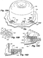
- Figures 15 , 15A, 15B, 15C , 15D and 16 show the air moving device 12 mounted in an opening 103 in a ceiling 104.
- a generally cylindrical can 105 mounts on and extends above the ceiling 104, and has an open can bottom 106, and a closed can top 107.
- the can top 107 includes a semi-circular, downward opening, circumferentially extending channel 108.
- a semi-circular fin 111 extends radially across the channel 108 to prevent swirling of the air before entering the air inlet 21. Additional fins may be used.
- a grill and support assembly 125 mounts to the ceiling and extends and connects to the exterior of the housing of device 12.
- a grill including spaced openings 110 between fins 109 to allow air to flow up from the room along the housing and past the cowling 19 into the inlet 21.
- the grill and support assembly 125 includes an outer ring 120 fastened to the underside of the ceiling including the convexly curved grill fins 109 with air openings 110 between connected outer ring 120 and an inner ring 121.
- Ring 121 has a spherical concave inner bearing surface 122.
- a ring 123 has a spherical convexly curved exterior bearing surface 124 is mounted on and affixed to the housing with bearing surfaces 122 and 124 mating in a frictional fit to support the housing to be at a vertical position or tilted at an angle to the vertical axis and be held by friction at the vertical axis or a selected angle relative to the vertical axis to direct air flow as required.
- the can 105 has an outwardly extending bottom flange 140 that fits against the underside of the ceiling 104.
- the can 105 preferably has four circumferentially spaced bottom openings 141 at 90 degree intervals that are rectangular in shape and extend up the can wall a short distance from the bottom flange 140.
- a clamping member 142 preferably made as a molded plastic body has a main body portion 143 above the ceiling 104 outside the can wall and an end flange portion 144 that fits inside the can opening 142.
- the main body portion 143 has a U-shaped outer wall portion 145 and an inner hub portion 146 having an aperture 147.
- the clamping member 142 inserts into the opening 141 via the open end of the can.
- a bolt fastener 151 extends through a hole in the flange, through a hole in the ceiling and threads into the aperture 147 in the main body portion to clamp the can 105 to the ceiling 104.
- the grill and support assembly 125 is mounted to the ceiling 104 and can 105 by a bolt fastener 149 extending through an aperture in ring 120, through the ceiling 104 and into a nut 150 in flange 140 in the can.
- a bolt fastener 149 extending through an aperture in ring 120, through the ceiling 104 and into a nut 150 in flange 140 in the can.
- the ceiling 104 typically would be a plasterboard ceiling in which a suitable hole is cut.
- a variation of Fig. 15 would be to extend or form the peripheral of outer ring 120 into a flat panel having a dimension of 2 ft. by 2 ft. that would fit in and be held by a grid that holds a conventional ceiling panel.
- an air moving device is fitted with an inlet grill 113, a light bulb style threaded male end 114 for threading into a light bulb socket, and a light bulb socket 115.
- the inlet grill 113 includes a plurality of circumferentially spaced grill fins 116 that attach to the first end of the housing 13.
- the grill fins 116 are separated by air intake slots 117, and extend axially outwardly from the first end 17 and curve radially inwardly to a flat circular mounting plate 119 that is substantially parallel with and spaced axially from the first end 17.
- Threaded male end 114 is mounted on and extends upwardly from the mounting plate 118.
- the socket 115 is mounted inside the housing 13 in a downwardly opening fashion so that light from a bulb 119 threaded into the socket 115 is directed downwards.
- the air moving device and system herein described has relatively low electrical power requirement.
- a typical fan motor is 35 watts at 1600 rpm for an impeller of 8.5" (21.6 cm) that will effectively move the air from the ceiling to the floor in a room having a ceiling height of 30 ft (9.1m).
- Another example is 75 watts with an impeller diameter 8.5" (21.6 cm) at 2300 rpm in a room having a ceiling height of 70 ft (21.3 m).
- stator 46 and housing 13 could be made as a single unit. It is also understood that the housing 13 may be made in two sections as for example a tubular section of a selected length may be added to the end of a truncated devices as shown in Figure 14 .
Landscapes
- Engineering & Computer Science (AREA)
- Mechanical Engineering (AREA)
- General Engineering & Computer Science (AREA)
- Chemical & Material Sciences (AREA)
- Combustion & Propulsion (AREA)
- Physics & Mathematics (AREA)
- Fluid Mechanics (AREA)
- Structures Of Non-Positive Displacement Pumps (AREA)
- Ventilation (AREA)
Claims (23)
- Structure comprenant une pièce (63), ladite pièce comprenant un plafond, un plancher et des parois latérales opposées et définissant un espace d'air et un dispositif de déplacement d'air positionné dans ladite pièce et monté au plafond (62), ledit dispositif de déplacement d'air étant sans tube vertical qui s'étend sensiblement du plafond au plancher et comprenant :un boîtier (13) ayant une entrée d'air (17) à une première extrémité et une sortie d'air (28) à une seconde extrémité espacée de ladite première extrémité avec un passage d'écoulement d'air entre ladite première et ladite seconde extrémité,un ventilateur rotatif (14) monté dans ledit boîtier à proximité de ladite entrée d'air et ayant une hélice (31) avec une pluralité de pales (33) qui produisent un écoulement d'air avec des composantes d'écoulement d'air rotative et axiale etune pluralité d'aubes de guidage d'air espacées s'étendant axialement (15) situées en aval dudit ventilateur rotatif (14) dans ledit boîtier entre ladite hélice et ladite sortie d'air pour convertir ladite composante rotative dudit écoulement d'air en écoulement d'air laminaire et en écoulement d'air axial combinés dans ledit boîtier, lesdites aubes étant espacées de ladite hélice par un intervalle (55) ayant une taille choisie qui est inférieure à la moitié du diamètre de l'hélice, ladite taille de l'intervalle étant choisie pour ne pas être supérieure à une dimension maximale choisie afin d'éviter la génération d'une turbulence et réduire la contre-pression statique dans ledit écoulement d'air, de sorte que ledit écoulement d'air sorte par ladite sortie d'air en courant axial s'étendant au-delà de ladite sortie d'air dans un motif colonnaire avec une dispersion latérale minimale etledit dispositif de déplacement d'air étant agencé en service pour aspirer de l'air chaud venant d'une zone proche dudit plafond (62), dans lequel l'air chaud quitte le dispositif de déplacement d'air dans une colonne (64) qui s'étend jusqu'au plancher (65) pour presser de l'air plus froid vers les parois latérales opposées (66) et vers le haut en direction du plafond (62).
- Structure selon la revendication 1, dans laquelle ledit intervalle (55) est choisi pour ne pas être inférieur à une dimension minimale choisie afin d'éviter le bruit.
- Structure selon la revendication 1, dans laquelle ledit passage d'écoulement d'air a une surface en coupe transversale qui diminue de ladite entrée d'air (17) à ladite sortie d'air (18) pour augmenter la vitesse de l'écoulement d'air.
- Structure selon la revendication 3, dans laquelle ladite surface en coupe transversale diminue d'environ 10 % à 35 %.
- Structure selon la revendication 1, dans laquelle chacune desdites pales (33) s'incline selon un angle choisi par rapport à un axe de rotation pour ladite hélice (31), chaque dite pale s'étendant axialement et radialement vers l'extérieur en direction de ladite seconde extrémité afin de produire ledit écoulement d'air dans ledit boîtier (13), chaque dite aube (15) ayant une partie d'aube incurvée inclinée selon un angle opposé à ladite inclinaison de chaque pale qui s'étend axialement et radialement vers l'intérieur en direction de ladite seconde extrémité pour aider à convertir ladite composante rotative dudit écoulement d'air en dit écoulement d'air laminaire et axial.
- Structure selon la revendication 1, dans laquelle lesdites aubes (15) sont rectilignes.
- Structure selon la revendication 1, dans laquelle le dispositif de déplacement d'air comprend un stator (46) et dans ledit boîtier (13) et séparable de celui-ci, et
dans lequel lesdites aubes (15) comprennent une partie amont (43) dans ledit stator et une partie aval (44) fixée à l'intérieur dudit boîtier en aval dudit stator, ladite partie aval fonctionnant conjointement avec ladite partie amont pour diriger ledit écoulement d'air à travers ledit boîtier. - Structure selon la revendication 1, dans laquelle le dispositif de déplacement d'air comprend un capotage (19) ayant une surface d'extrémité externe avec un rayon uniforme à ladite première extrémité qui dirige l'écoulement d'air à ladite entrée d'air (17) pour qu'il s'écoule dans ledit boîtier le long d'une courbe afin de minimiser la turbulence et le bruit.
- Structure selon la revendication 1, dans laquelle ledit boîtier (13) a une surface interne qui est sensiblement uniforme et ininterrompue pour minimiser la turbulence et la perte d'énergie, un moyeu de boîtier interne (16) dans ledit boîtier ayant une partie de moyeu de boîtier aval (57) vers l'intérieur desdites aubes (15) et à distance de celles-ci pour réduire la turbulence dans ledit écoulement d'air le long desdites aubes, ledit moyeu de boîtier ayant une forme de torpille convergeant vers ladite seconde extrémité pour diriger l'écoulement d'air afin d'éviter une turbulence.
- Structure selon la revendication 1, dans laquelle ledit dispositif de déplacement d'air comprend une suspension (23) raccordée à pivotement audit boîtier (13) pour monter ledit boîtier de manière dépendante à un support, ladite suspension permettant audit boîtier de se déplacer selon des angles choisis, ladite suspension pouvant être bloquée dans ledit angle choisi afin de diriger l'écoulement d'air selon ledit angle choisi.
- Structure selon la revendication 1, dans laquelle ledit dispositif de déplacement d'air comprend des moyens pour fixer ledit boîtier à une lampe sous gaine (70) encastrée dans un plafond pour suspendre ledit boîtier (13) à ladite lampe sous gaine, lesdits moyens de fixation comprenant un connecteur électrique (69) ayant une extrémité mâle extérieurement filetée (77) se connectant à une douille d'ampoule de lampe au dos de ladite gaine de lampe, une plaque de montage (74) à ladite première extrémité, un tube (76) fixé à la partie supérieure de la plaque de montage, lesdits moyens de fixation comprenant un ressort de compression (75) dans ledit tube, un arbre (78) se télescopant dans ledit tube et pouvant y glisser axialement et des parties de cale (78A) et de fente (76A) coopérantes emboîtées sur le tube et l'arbre afin d'empêcher une rotation relative entre ledit tube et ledit arbre, ladite extrémité mâle étant supportée à l'extrémité dudit arbre opposée audit ressort, ledit ressort pressant ladite extrémité mâle dans ladite douille.
- Structure selon la revendication 1, dans laquelle ledit dispositif de déplacement d'air comprend un connecteur électrique ayant une extrémité mâle extérieurement filetée (114) montée sur la partie supérieure du boîtier (13) pour se connecter à une douille d'ampoule de lampe (115),
une grille (113) sur ledit boîtier pour permettre à l'air de pénétrer dans ladite entrée (17) et une douille d'ampoule de lampe électrique montée à l'intérieur dudit boîtier pour éclairer la pièce dans laquelle le boîtier est monté. - Structure selon la revendication 1, dans laquelle ledit dispositif de déplacement d'air comprend un ensemble de grille et de support (125) monté au plafond (104) et ledit boîtier (13) et ledit ensemble ayant une première surface d'appui extérieure sphérique à incurvation convexe (124) s'étendant radialement vers l'intérieur et ayant une seconde surface d'appui extérieure sphérique à incurvation concave (122) coopérant avec ladite première surface d'appui et s'engageant par frottement avec celui-ci afin de supporter ledit boîtier (13) audit plafond et permettre audit boîtier d'être vertical et de s'incliner selon des angles choisis avec la verticale ainsi que d'être soutenu par frottement dans une position choisie.
- Structure selon la revendication 13, dans laquelle ledit dispositif de déplacement d'air comprend une grille à incurvation concave et ayant des ailettes de grille espacées (109) et des ouvertures d'air (110) s'étendant entre un anneau externe (120) fixé audit plafond (104) et un anneau interne (121) connecté auxdites ailettes de grille afin d'aménager ladite première surface d'appui (124) pour permettre à de l'air de s'écouler vers le haut à travers ladite grille le long dudit boîtier dans ladite entrée.
- Structure selon la revendication 14, dans laquelle ledit dispositif de déplacement d'air comprend une gaine (105) ayant une bride inférieure (140) et un fond ouvert (141) s'étendant autour dudit boîtier raccordé audit plafond (104) pour enserrer la partie supérieure dudit boîtier et au moins une ailette dans un canal dans une partie supérieure de ladite gaine afin d'empêcher un tourbillonnement de l'air avant qu'il ne pénètre dans ladite entrée.
- Structure selon la revendication 14, dans laquelle ledit dispositif de déplacement d'air comprend un élément de serrage (142) ayant une partie de corps principale et une partie de bride à une extrémité de ladite partie de corps principale, ladite partie de bride étant disposée dans une ouverture (141) de ladite gaine (105) sur ledit fond ouvert, une fixation s'étendant à travers une bride inférieure de ladite gaine, ledit plafond (104) se raccordant à ladite partie de corps principale afin de serrer ladite gaine sur ledit plafond.
- Structure selon la revendication 16, dans laquelle il y a une pluralité desdits éléments de serrage (142) dans des positions circonférentiellement espacées sur ladite gaine (105).
- Structure selon la revendication 1, dans laquelle le dispositif de déplacement d'air comprend une conduite d'eau dans ledit boîtier avec une buse (84) à une extrémité pour former un brouillard dans l'air qui se décharge de ladite seconde extrémité (28) afin de réduire la température de l'air.
- Structure selon la revendication 1, dans laquelle le nombre desdites pales (33) est différent du nombre desdites aubes (15) pour minimiser le bruit.
- Structure selon la revendication 1, dans laquelle il y a trois dites pales (33) et quatre dites aubes (15).
- Structure selon la revendication 1, dans laquelle :le boîtier (13) a une première section, une seconde section en aval de ladite première section avec un diamètre plus petit que ladite première section, et une tablette interne (26) s'étendant radialement vers l'intérieur de ladite première section à ladite seconde section,un stator (46) est niché dans ladite première section et repose sur ladite tablette,le ventilateur rotatif (14) est monté en amont d'un moyeu de boîtier (16) et l'hélice (31) a un moyeu d'hélice (32) ayant une surface externe et la pluralité de pales (33) s'étend radialement vers l'extérieur dudit moyeu d'hélice, ladite surface interne et ladite surface externe définissent un passage d'écoulement d'air à travers ledit boîtier (13) entre lesdites première et seconde extrémités, les pales produisent un écoulement d'air à travers ledit passage d'écoulement d'air avec une composante d'écoulement d'air rotative et axiale, et le ventilateur rotatif (14) se niche dans ledit boîtier en amont dudit stator, etun capotage (19) est monté sur ledit boîtier en amont dudit ventilateur et s'étend radialement vers l'intérieur dans ledit boîtier le long d'une courbe pour minimiser la turbulence, etlesdites aubes (15) comprennent une partie amont dans ledit stator (46) et une partie aval fixée à l'intérieur dudit boîtier (13).
- Procédé de déplacement d'air dans une pièce comprenant un plafond, un plancher et des parois latérales opposées qui définissent un espace d'air, comprenant les étapes consistant à :produire un écoulement d'air à travers un dispositif de déplacement d'air, ledit dispositif de déplacement d'air étant sans un tube vertical qui s'étend sensiblement du plafond au plancher et ayant un boîtier allongé (13) d'une entrée d'air (17) à une première extrémité à une sortie d'air (18) à une seconde extrémité, espacée de ladite première extrémité, ledit dispositif de déplacement d'air ayant également dans ledit boîtier, monté à proximité de ladite entrée d'air, un ventilateur rotatif ayant une hélice, et entre ladite hélice et ladite sortie d'air, une pluralité d'aubes de guidage d'air espacées s'étendant axialement situées en aval dudit ventilateur rotatif (14), lesdites aubes étant espacées de ladite hélice avec un intervalle ayant une taille choisie qui est inférieure à la moitié du diamètre de l'hélice, etdiriger ledit écoulement d'air à travers ledit boîtier selon un écoulement laminaire et axial et à l'extérieur par ladite sortie d'air afin de produire un courant axial s'étendant au-delà de ladite sortie d'air selon un motif colonnaire avec une dispersion latérale minimale de manière à diriger de l'air chaud aspiré dans l'entrée d'air (17) du voisinage du plafond (62) au plancher (65) pour presser de l'air plus froid vers les parois latérales opposées (66) et vers le haut en direction du plafond (62).
- Procédé selon la revendication 22, dans lequel ledit écoulement d'air est dirigé verticalement ou selon un angle choisi avec la verticale afin de pénétrer dans l'espace d'air, pour entraîner une déstratification de l'espace d'air et une circulation d'écoulement d'air.
Priority Applications (2)
| Application Number | Priority Date | Filing Date | Title |
|---|---|---|---|
| EP17175578.8A EP3273173A1 (fr) | 2004-03-15 | 2005-02-28 | Dispositifs de déplacement d'air en colonne, systèmes et procédés |
| EP12160654A EP2503254A1 (fr) | 2004-03-15 | 2005-02-28 | Dispositifs de déplacement d'air en colonne, systèmes et procédés |
Applications Claiming Priority (2)
| Application Number | Priority Date | Filing Date | Title |
|---|---|---|---|
| US55372004P | 2004-03-15 | 2004-03-15 | |
| PCT/US2005/006419 WO2005091896A2 (fr) | 2004-03-15 | 2005-02-28 | Dispositifs, systemes et procedes de deplacement d'air en colonne |
Related Child Applications (4)
| Application Number | Title | Priority Date | Filing Date |
|---|---|---|---|
| EP12160654A Division-Into EP2503254A1 (fr) | 2004-03-15 | 2005-02-28 | Dispositifs de déplacement d'air en colonne, systèmes et procédés |
| EP12160654A Division EP2503254A1 (fr) | 2004-03-15 | 2005-02-28 | Dispositifs de déplacement d'air en colonne, systèmes et procédés |
| EP17175578.8A Division-Into EP3273173A1 (fr) | 2004-03-15 | 2005-02-28 | Dispositifs de déplacement d'air en colonne, systèmes et procédés |
| EP17175578.8A Division EP3273173A1 (fr) | 2004-03-15 | 2005-02-28 | Dispositifs de déplacement d'air en colonne, systèmes et procédés |
Publications (3)
| Publication Number | Publication Date |
|---|---|
| EP1735568A2 EP1735568A2 (fr) | 2006-12-27 |
| EP1735568A4 EP1735568A4 (fr) | 2009-06-03 |
| EP1735568B1 true EP1735568B1 (fr) | 2018-02-14 |
Family
ID=35056671
Family Applications (3)
| Application Number | Title | Priority Date | Filing Date |
|---|---|---|---|
| EP17175578.8A Withdrawn EP3273173A1 (fr) | 2004-03-15 | 2005-02-28 | Dispositifs de déplacement d'air en colonne, systèmes et procédés |
| EP05714125.1A Expired - Lifetime EP1735568B1 (fr) | 2004-03-15 | 2005-02-28 | Dispositifs, systemes et procedes de deplacement d'air en colonne |
| EP12160654A Withdrawn EP2503254A1 (fr) | 2004-03-15 | 2005-02-28 | Dispositifs de déplacement d'air en colonne, systèmes et procédés |
Family Applications Before (1)
| Application Number | Title | Priority Date | Filing Date |
|---|---|---|---|
| EP17175578.8A Withdrawn EP3273173A1 (fr) | 2004-03-15 | 2005-02-28 | Dispositifs de déplacement d'air en colonne, systèmes et procédés |
Family Applications After (1)
| Application Number | Title | Priority Date | Filing Date |
|---|---|---|---|
| EP12160654A Withdrawn EP2503254A1 (fr) | 2004-03-15 | 2005-02-28 | Dispositifs de déplacement d'air en colonne, systèmes et procédés |
Country Status (10)
| Country | Link |
|---|---|
| US (2) | US7381129B2 (fr) |
| EP (3) | EP3273173A1 (fr) |
| JP (1) | JP2007529681A (fr) |
| KR (1) | KR20060130251A (fr) |
| AU (1) | AU2005227197B2 (fr) |
| CA (1) | CA2559610C (fr) |
| NZ (1) | NZ549851A (fr) |
| PL (2) | PL398557A1 (fr) |
| RU (1) | RU2365828C2 (fr) |
| WO (1) | WO2005091896A2 (fr) |
Families Citing this family (79)
| Publication number | Priority date | Publication date | Assignee | Title |
|---|---|---|---|---|
| US20120195749A1 (en) | 2004-03-15 | 2012-08-02 | Airius Ip Holdings, Llc | Columnar air moving devices, systems and methods |
| US7381129B2 (en) * | 2004-03-15 | 2008-06-03 | Airius, Llc. | Columnar air moving devices, systems and methods |
| US20070160478A1 (en) * | 2005-12-29 | 2007-07-12 | Minebea Co., Ltd. | Fan blade with non-varying stagger and camber angels |
| ATE474138T1 (de) * | 2006-10-28 | 2010-07-15 | Hoernig Maria | Windkraftanlage sowie verfahren zur erzeugung von elektrischer energie aus bewegter umgebungsluft |
| US7726945B2 (en) * | 2007-02-08 | 2010-06-01 | Rite-Hite Holding Corporation | Industrial ceiling fan |
| US8419514B2 (en) * | 2008-02-27 | 2013-04-16 | James McKeown | Apparatus for circulating air |
| US8888711B2 (en) | 2008-04-08 | 2014-11-18 | Carefusion 203, Inc. | Flow sensor |
| US8616842B2 (en) | 2009-03-30 | 2013-12-31 | Airius Ip Holdings, Llc | Columnar air moving devices, systems and method |
| US9335061B2 (en) * | 2008-05-30 | 2016-05-10 | Airius Ip Holdings, Llc | Columnar air moving devices, systems and methods |
| US9151295B2 (en) | 2008-05-30 | 2015-10-06 | Airius Ip Holdings, Llc | Columnar air moving devices, systems and methods |
| KR20100065779A (ko) * | 2008-12-08 | 2010-06-17 | 삼성전자주식회사 | 회전가능한 배터리 팩 |
| US8177141B2 (en) * | 2008-12-19 | 2012-05-15 | Zodiac Pool Systems, Inc. | Laminar deck jet |
| US8042748B2 (en) * | 2008-12-19 | 2011-10-25 | Zodiac Pool Systems, Inc. | Surface disruptor for laminar jet fountain |
| KR101395177B1 (ko) * | 2009-03-04 | 2014-05-15 | 다이슨 테크놀러지 리미티드 | 선풍기 |
| USD631536S1 (en) | 2009-05-21 | 2011-01-25 | Rite-Hite Holding Corporation | Fan blade |
| US20100326103A1 (en) * | 2009-06-24 | 2010-12-30 | Karcher North America, Inc. | Dehumidifier for Use in Water Damage Restoration |
| EP3251716B1 (fr) * | 2009-08-11 | 2019-02-20 | ResMed Motor Technologies Inc | Ventilateur avec un appareil de soufflage à symétrie axiale et à un seul étage |
| KR100972007B1 (ko) * | 2009-10-06 | 2010-07-22 | 정선엔지니어링 주식회사 | 대공간용 공기조화기 |
| US20110105015A1 (en) * | 2009-10-30 | 2011-05-05 | Exaflop Llc | Convection Cooling of Data Center Using Chimney |
| UA107094C2 (xx) | 2009-11-03 | 2014-11-25 | Відцентровий стельовий вентилятор | |
| US8640360B2 (en) * | 2010-01-08 | 2014-02-04 | Karcher North America, Inc. | Integrated water damage restoration system, sensors therefor, and method of using same |
| US8502410B2 (en) | 2010-02-04 | 2013-08-06 | Daimler Ag | Method of operating a vehicle and electric powertrain |
| USD631148S1 (en) | 2010-06-08 | 2011-01-18 | Zoo Fans Incorporated | Destratification fan |
| TW201228543A (en) * | 2010-12-31 | 2012-07-01 | Hon Hai Prec Ind Co Ltd | Mounting apparatus for fan |
| EP2721352B1 (fr) | 2011-06-15 | 2015-09-16 | Airius IP Holdings, LLC | Dispositifs et systèmes de déplacement d'air en colonne |
| TWM442484U (en) * | 2011-12-12 | 2012-12-01 | Zhen-Ming Su | Hot/cold air radiation and convection transfer device |
| JP6082520B2 (ja) | 2011-12-20 | 2017-02-15 | ミネベアミツミ株式会社 | 軸流ファンに用いられるインペラ、およびそれを用いた軸流ファン |
| US8894478B1 (en) * | 2012-01-06 | 2014-11-25 | Woodrow Stillwagon | Environmental improvement system |
| WO2013133735A2 (fr) * | 2012-01-30 | 2013-09-12 | Kleshkanov Vladimir Ivanovich | Système de chauffage à économie d'énergie |
| US9163639B2 (en) | 2012-02-23 | 2015-10-20 | Valco Companies, Inc. | Air mixing device for buildings |
| USD698916S1 (en) | 2012-05-15 | 2014-02-04 | Airius Ip Holdings, Llc | Air moving device |
| US9175697B1 (en) * | 2012-11-15 | 2015-11-03 | Bradley K. Kadau | Fan with light socket attachment |
| KR102057957B1 (ko) * | 2013-04-19 | 2019-12-20 | 엘지전자 주식회사 | 터보팬 및 이를 사용한 천정형 공기조화기 |
| JP6180020B2 (ja) | 2013-08-29 | 2017-08-16 | ミネベアミツミ株式会社 | 軸流ファンモータ |
| US20150104159A1 (en) * | 2013-10-16 | 2015-04-16 | Restless Noggins Design, Llc | Heating and cooling apparatus |
| CA2875339A1 (fr) | 2013-12-19 | 2015-06-19 | Airius Ip Holdings, Llc | Dispositifs, systemes et procedes de deplacement d'air en colonne |
| CA2875347C (fr) | 2013-12-19 | 2022-04-19 | Airius Ip Holdings, Llc | Dispositifs, systemes et procedes de deplacement d'air en colonne |
| AU2015269672B2 (en) | 2014-06-06 | 2019-05-16 | Airius Ip Holdings, Llc | Columnar air moving devices, systems and methods |
| KR101693378B1 (ko) * | 2015-06-30 | 2017-01-05 | (주)구츠 | 국소 송풍 구조를 갖는 팬코일 유닛 |
| EP3324782B1 (fr) * | 2015-07-24 | 2024-06-19 | Koninklijke Philips N.V. | Dispositif de soin capillaire |
| ES2551983B1 (es) * | 2015-08-03 | 2016-10-19 | Confort Direct, S.L. | Destratificador de uso doméstico |
| CN105455566B (zh) * | 2015-12-25 | 2017-01-18 | 重庆星源玻璃器皿有限责任公司 | 反重力式水杯制作方法 |
| CN106996392A (zh) * | 2016-01-26 | 2017-08-01 | 建准电机工业股份有限公司 | 风扇及其扇轮、平衡扇轮配重的方法及扇轮平衡系统 |
| US10267340B2 (en) * | 2016-02-24 | 2019-04-23 | International Business Machines Corporation | Concentrically symmetric connector in blind mate round fan assembly |
| DE102016002997A1 (de) * | 2016-03-14 | 2017-09-14 | H. Doll Wärmetechnik GmbH | Deckenventilator mit Strömungsleitmitteln und Verfahren hierzu |
| US10156375B2 (en) * | 2016-03-14 | 2018-12-18 | Hee Bum Oh | Air exhaust apparatus |
| USD805176S1 (en) | 2016-05-06 | 2017-12-12 | Airius Ip Holdings, Llc | Air moving device |
| USD820967S1 (en) | 2016-05-06 | 2018-06-19 | Airius Ip Holdings Llc | Air moving device |
| KR101843636B1 (ko) * | 2016-05-12 | 2018-03-29 | 정상원 | 안개 선풍기 |
| DE102016007205A1 (de) * | 2016-06-08 | 2017-12-14 | Ziehl-Abegg Se | Ventilatoreinheit |
| US10487852B2 (en) | 2016-06-24 | 2019-11-26 | Airius Ip Holdings, Llc | Air moving device |
| DE102016119916A1 (de) | 2016-10-19 | 2018-04-19 | Ebm-Papst Mulfingen Gmbh & Co. Kg | Ventilator mit Ventilatorrad und Leitrad |
| US10260367B2 (en) | 2016-11-02 | 2019-04-16 | Jay HASKIN | Power transmission system for turbines or compressors having counter-rotating blades |
| USD886275S1 (en) * | 2017-01-26 | 2020-06-02 | Airius Ip Holdings, Llc | Air moving device |
| US11359643B2 (en) | 2017-03-20 | 2022-06-14 | Shop Vac Corporation | Fan having housing formed by connectable pieces and including air guide ribs and an internal ramp |
| JP2018189050A (ja) * | 2017-05-10 | 2018-11-29 | 北上電設工業株式会社 | 送風装置 |
| USD885550S1 (en) | 2017-07-31 | 2020-05-26 | Airius Ip Holdings, Llc | Air moving device |
| CN209638120U (zh) | 2017-10-20 | 2019-11-15 | 创科(澳门离岸商业服务)有限公司 | 风扇 |
| US10876545B2 (en) * | 2018-04-09 | 2020-12-29 | Vornado Air, Llc | System and apparatus for providing a directed air flow |
| RU184748U1 (ru) * | 2018-07-12 | 2018-11-07 | Частное Акционерное Общество "Вентиляционные системы" | Осевой вентилятор |
| US10845065B1 (en) * | 2018-12-11 | 2020-11-24 | Gabriel Rosario | Air fan with ice compartment |
| US11187421B2 (en) | 2019-01-15 | 2021-11-30 | Home Depot Product Authority, Llc | Misting fan |
| USD987054S1 (en) * | 2019-03-19 | 2023-05-23 | Airius Ip Holdings, Llc | Air moving device |
| USD887541S1 (en) * | 2019-03-21 | 2020-06-16 | Airius Ip Holdings, Llc | Air moving device |
| US11598539B2 (en) | 2019-04-17 | 2023-03-07 | Airius Ip Holdings, Llc | Air moving device with bypass intake |
| JP6724220B1 (ja) * | 2019-08-05 | 2020-07-15 | 株式会社ニトリホールディングス | 空気清浄装置 |
| CN112797563B (zh) * | 2019-10-28 | 2025-05-06 | 北海新能(北京)科技有限公司 | 一种空气净化器及空气净化方法 |
| CN114867944B (zh) | 2019-12-09 | 2024-01-26 | Lg电子株式会社 | 送风机 |
| CN112096625A (zh) * | 2020-09-15 | 2020-12-18 | 开平市永强风机实业有限公司 | 一种风机 |
| USD963834S1 (en) * | 2020-10-27 | 2022-09-13 | Gregory S. Daniels | Roof vent with a circular integrated fan |
| USD964546S1 (en) * | 2020-10-27 | 2022-09-20 | Gregory S. Daniels | Roof vent with a circular integrated fan |
| US11460043B2 (en) * | 2020-11-03 | 2022-10-04 | Manaslu Technology (Shanghai) Co., Ltd. | Internal and external dual-purpose air pump, inflatable product and lifting handle device |
| FI129583B (fi) * | 2021-04-29 | 2022-05-13 | Napalmi Tietotekniikka Oy | Puhallin |
| CN113280429B (zh) * | 2021-05-13 | 2022-08-02 | 中颐工科工程技术有限公司 | 一种绿色建筑用室内通风调节智能控制系统 |
| US11946488B2 (en) * | 2021-06-09 | 2024-04-02 | Glenn B. Smith | Fruit or vegetable shaped fan for dispersing airborne eye irritants |
| CN113478222B (zh) * | 2021-07-15 | 2022-04-22 | 宁波四维尔汽车智能科技有限公司 | 一种汽车空调出风口总成组装流水线 |
| KR102459524B1 (ko) * | 2022-05-24 | 2022-10-27 | 주식회사 근옥 | 터보 중계팬 |
| WO2024054133A2 (fr) * | 2022-09-06 | 2024-03-14 | Общество С Ограниченной Ответственностью "Ивл Турботехнологии" | Compresseur centrifuge pour appareil de ventilation artificielle des poumons |
| KR102575502B1 (ko) * | 2022-12-19 | 2023-09-07 | 첨단정보시스템 (주) | 사이클론 환풍기 덕트 공조 설비 |
Family Cites Families (79)
| Publication number | Priority date | Publication date | Assignee | Title |
|---|---|---|---|---|
| US917206A (en) * | 1908-12-04 | 1909-04-06 | Charles James Watts | Circulator. |
| US2154313A (en) * | 1938-04-01 | 1939-04-11 | Gen Electric | Directing vane |
| US2371821A (en) * | 1943-06-02 | 1945-03-20 | Aaron J Havis | Air blower |
| GB792369A (en) * | 1955-01-24 | 1958-03-26 | Airscrew Company & Jicwood Ltd | Improvements in axial flow fans |
| FR1315717A (fr) * | 1960-12-19 | 1963-01-25 | Lyonnaise Ventilation | Ventilateur hélicoïde perfectionné |
| US3165294A (en) * | 1962-12-28 | 1965-01-12 | Gen Electric | Rotor assembly |
| CH423076A (de) * | 1964-05-29 | 1966-10-31 | Ventilator Ag | Schaufelrad für Axialgebläse und Verfahren zu dessen Herstellung |
| AU459701B2 (en) * | 1968-10-25 | 1975-03-18 | Electric fans | |
| US3524399A (en) * | 1969-06-19 | 1970-08-18 | Acme Eng & Mfg Corp | Heating,ventilating and circulating air system |
| US3876331A (en) * | 1972-11-22 | 1975-04-08 | Robert Denherder | Removable propeller blade assembly |
| US3827342A (en) * | 1973-10-11 | 1974-08-06 | G Hughes | Air circulating device |
| US3932054A (en) * | 1974-07-17 | 1976-01-13 | Western Engineering & Mfg. Co. | Variable pitch axial fan |
| US3973479A (en) * | 1975-06-23 | 1976-08-10 | Whiteley Isaac C | Floor-ceiling air circulating device |
| US4185545A (en) * | 1977-01-10 | 1980-01-29 | Martin David A | Air circulator |
| US4123197A (en) * | 1977-02-04 | 1978-10-31 | Allware Agencies Limited | Fan with air directing grille |
| US4152973A (en) * | 1977-09-16 | 1979-05-08 | Peterson Fred M | Heat energy homogenizer |
| JPS5532965A (en) * | 1978-08-29 | 1980-03-07 | Masakiyo Nakaema | Circulator |
| US4344112A (en) * | 1980-10-06 | 1982-08-10 | Brown Robert L | Environmental lamp |
| US4396352A (en) * | 1981-07-17 | 1983-08-02 | Trw Inc. | Pitch adjustment for blades of ceiling fan |
| US4512242A (en) * | 1982-06-11 | 1985-04-23 | Acme Engineering & Manufacturing Corp. | Heat destratification method and system |
| US4550649A (en) * | 1982-07-31 | 1985-11-05 | Marco Zambolin | Process and apparatus for reducing the temperature gradient in buildings |
| US4522255A (en) * | 1982-08-05 | 1985-06-11 | Baker Gary C | Spot thermal or environmental conditioner |
| US4473000A (en) * | 1982-11-26 | 1984-09-25 | Vertical Air Stabilization Corp. | Air blower with air directing vanes |
| US4515538A (en) * | 1983-10-07 | 1985-05-07 | Degeorge Ceilings, Inc. | Ceiling fan |
| US4548548A (en) * | 1984-05-23 | 1985-10-22 | Airflow Research And Manufacturing Corp. | Fan and housing |
| US4657483A (en) * | 1984-11-16 | 1987-04-14 | Bede James D | Shrouded household fan |
| US4662912A (en) * | 1986-02-27 | 1987-05-05 | Perkins Lynn W | Air purifying and stabilizing blower |
| US4730551A (en) * | 1986-11-03 | 1988-03-15 | Peludat Walter W | Heat distributor for suspended ceilings |
| US4849862A (en) * | 1988-02-19 | 1989-07-18 | Mega/Erg Inc. | Suspended air purifier light fixture |
| SU1702116A1 (ru) * | 1989-01-03 | 1991-12-30 | Головное специализированное конструкторское бюро по комплексу оборудования для микроклимата | Вентил торна установка |
| US4971143A (en) * | 1989-05-22 | 1990-11-20 | Carrier Corporation | Fan stator assembly for heat exchanger |
| US4930987A (en) * | 1989-05-24 | 1990-06-05 | Brad Stahl | Marine propeller and hub assembly of plastic |
| SU1665199A1 (ru) * | 1989-07-11 | 1991-07-23 | А.И.Степанов и В.С.Заверткин | Воздухораспределительное устройство |
| US5042366A (en) * | 1990-05-03 | 1991-08-27 | Panetski Judith A | Decorative air temperature equalizing column for room |
| US5033711A (en) * | 1990-06-04 | 1991-07-23 | Airmaster Fan Company | Universal bracket for fans |
| US5152606A (en) * | 1990-07-27 | 1992-10-06 | General Signal Corporation | Mixer impeller shaft attachment apparatus |
| US5078574A (en) * | 1990-11-19 | 1992-01-07 | Olsen George D | Device for minimizing room temperature gradients |
| US5358443A (en) * | 1993-04-14 | 1994-10-25 | Centercore, Inc. | Dual fan hepa filtration system |
| CH687637A5 (de) * | 1993-11-04 | 1997-01-15 | Micronel Ag | Axialkleinventilator. |
| US5494404A (en) * | 1993-12-22 | 1996-02-27 | Alliedsignal Inc. | Insertable stator vane assembly |
| JPH07253231A (ja) * | 1994-03-15 | 1995-10-03 | Sekisui Chem Co Ltd | 建物の壁部に組み込まれる室内空気浄化装置 |
| DE4413542A1 (de) * | 1994-04-19 | 1995-10-26 | Stulz Gmbh | Vorrichtung und Verfahren zum Kühlen von Großräumen |
| US5429481A (en) * | 1994-08-24 | 1995-07-04 | Liu; Su-Liang | Angle-adjustable joint for electric fans |
| US5513953A (en) * | 1994-09-13 | 1996-05-07 | Hansen; Clint W. | Suspended ceiling fan |
| US5564980A (en) * | 1995-02-09 | 1996-10-15 | Becker; Sydney J. | Room air quality conditioning system |
| JP3641252B2 (ja) * | 1995-06-01 | 2005-04-20 | 松下エコシステムズ株式会社 | 送風機 |
| US5584656A (en) * | 1995-06-28 | 1996-12-17 | The Scott Fetzer Company | Flexible impeller for a vacuum cleaner |
| US5613833A (en) * | 1995-10-30 | 1997-03-25 | Holmes Products Corp. | Quick release tilt adjustment mechanism |
| US5884500A (en) * | 1996-09-25 | 1999-03-23 | Floratech Industries, Inc. | Self-contained air conditioner with discharge-air filter |
| US5934362A (en) * | 1997-01-21 | 1999-08-10 | Tele-Flow, Inc. | Combination bath fan, register box, air conditioning and heating boot |
| US6030287A (en) * | 1997-03-20 | 2000-02-29 | Core; William Roger | System for distributing air through a ceiling in a room |
| US6004097A (en) * | 1997-09-26 | 1999-12-21 | Sure Alloy Steel Corp. | Coal mill exhauster fan |
| US6004365A (en) * | 1997-10-17 | 1999-12-21 | Fiacco; Paul | Air filtering device |
| AU1097099A (en) * | 1997-10-21 | 1999-05-10 | Lloyd L. Lautzenhiser | Adaptive frequency-hopping oscillators |
| US6109874A (en) * | 1998-02-17 | 2000-08-29 | Steiner; Gregory A. | Portable fan device |
| US5997253A (en) * | 1998-07-09 | 1999-12-07 | Brunswick Corporation | Adjustable pitch propeller |
| US6073857A (en) * | 1998-09-14 | 2000-06-13 | Fairlane Tool Company | Co-generator utilizing micro gas turbine engine |
| IT1304683B1 (it) * | 1998-10-08 | 2001-03-28 | Gate Spa | Convogliatore d'aria per un elettroventilatore, particolarmente per ilradiatore di un autoveicolo. |
| US6145798A (en) * | 1998-12-01 | 2000-11-14 | Markrep Associates, Inc. | Quick release fan mount |
| JP3268279B2 (ja) * | 1999-01-18 | 2002-03-25 | 三菱電機株式会社 | 空気調和機 |
| AU2826900A (en) * | 1999-03-08 | 2000-09-28 | Michihiko Kawano | Method of ventilating by rotating air flow |
| US6149513A (en) * | 1999-07-12 | 2000-11-21 | Carrier Corporation | Ceiling grille for air conditioner of recreational vehicle |
| US6168517B1 (en) * | 1999-10-29 | 2001-01-02 | E. F. Cook | Recirculating air mixer and fan with lateral air flow |
| US6302640B1 (en) * | 1999-11-10 | 2001-10-16 | Alliedsignal Inc. | Axial fan skip-stall |
| US6458028B2 (en) * | 1999-12-17 | 2002-10-01 | Darryl L. Snyder | Diffuser and ceiling fan combination |
| US6360816B1 (en) * | 1999-12-23 | 2002-03-26 | Agilent Technologies, Inc. | Cooling apparatus for electronic devices |
| JP2001193979A (ja) * | 2000-01-13 | 2001-07-17 | Go Sekkei Kenkyusho:Kk | 室内空気再循環装置 |
| US6352473B1 (en) * | 2000-03-10 | 2002-03-05 | Thomas L. Clark | Windjet turbine |
| US6471738B1 (en) * | 2000-03-22 | 2002-10-29 | Health & Home Technologies | Ceiling-mounted air filtration device |
| RU2189536C1 (ru) * | 2001-03-19 | 2002-09-20 | ООО "КлиматВентМаш" | Вентиляционная установка |
| US6592328B1 (en) * | 2001-04-17 | 2003-07-15 | Emerson Electric Co. | Method and apparatus for adjusting the pitch of a fan blade |
| US6575011B1 (en) * | 2001-04-19 | 2003-06-10 | The United States Of America As Represented By The Secretary Of The Navy | Blade tip clearance probe and method for measuring blade tip clearance |
| US6484524B1 (en) * | 2001-07-12 | 2002-11-26 | Gennaty Ulanov | System of and a method of cooling an interior of a room provided with a wall air conditioning unit |
| US6581974B1 (en) * | 2001-09-29 | 2003-06-24 | Ragner Manufacturing, Llc | Pivot adaptor attachment for vacuum cleaners |
| US7381129B2 (en) * | 2004-03-15 | 2008-06-03 | Airius, Llc. | Columnar air moving devices, systems and methods |
| US7056092B2 (en) * | 2004-04-09 | 2006-06-06 | Stahl Bradford C | Modular propeller |
| US7214035B2 (en) * | 2005-02-18 | 2007-05-08 | Mario Bussières | Rotor for a turbomachine |
| CN100554188C (zh) * | 2006-06-27 | 2009-10-28 | 吴为国 | 水车式增氧机的叠装式叶轮 |
| US8616842B2 (en) * | 2009-03-30 | 2013-12-31 | Airius Ip Holdings, Llc | Columnar air moving devices, systems and method |
-
2004
- 2004-12-30 US US11/027,039 patent/US7381129B2/en not_active Expired - Lifetime
-
2005
- 2005-02-28 PL PL398557A patent/PL398557A1/pl not_active Application Discontinuation
- 2005-02-28 EP EP17175578.8A patent/EP3273173A1/fr not_active Withdrawn
- 2005-02-28 PL PL382705A patent/PL382705A1/pl not_active IP Right Cessation
- 2005-02-28 JP JP2007503918A patent/JP2007529681A/ja active Pending
- 2005-02-28 RU RU2006132914/06A patent/RU2365828C2/ru active
- 2005-02-28 NZ NZ549851A patent/NZ549851A/en not_active IP Right Cessation
- 2005-02-28 EP EP05714125.1A patent/EP1735568B1/fr not_active Expired - Lifetime
- 2005-02-28 CA CA2559610A patent/CA2559610C/fr not_active Expired - Lifetime
- 2005-02-28 KR KR1020067021292A patent/KR20060130251A/ko not_active Ceased
- 2005-02-28 WO PCT/US2005/006419 patent/WO2005091896A2/fr not_active Ceased
- 2005-02-28 AU AU2005227197A patent/AU2005227197B2/en not_active Expired
- 2005-02-28 EP EP12160654A patent/EP2503254A1/fr not_active Withdrawn
-
2008
- 2008-05-30 US US12/130,909 patent/US20080227381A1/en not_active Abandoned
Non-Patent Citations (1)
| Title |
|---|
| None * |
Also Published As
| Publication number | Publication date |
|---|---|
| WO2005091896A3 (fr) | 2007-06-07 |
| US7381129B2 (en) | 2008-06-03 |
| RU2006132914A (ru) | 2008-04-27 |
| US20080227381A1 (en) | 2008-09-18 |
| EP3273173A1 (fr) | 2018-01-24 |
| PL398557A1 (pl) | 2012-08-13 |
| WO2005091896A2 (fr) | 2005-10-06 |
| CA2559610C (fr) | 2013-04-09 |
| EP1735568A2 (fr) | 2006-12-27 |
| AU2005227197B2 (en) | 2011-09-08 |
| US20050202776A1 (en) | 2005-09-15 |
| EP2503254A1 (fr) | 2012-09-26 |
| JP2007529681A (ja) | 2007-10-25 |
| CA2559610A1 (fr) | 2005-10-06 |
| RU2365828C2 (ru) | 2009-08-27 |
| PL382705A1 (pl) | 2007-11-26 |
| EP1735568A4 (fr) | 2009-06-03 |
| KR20060130251A (ko) | 2006-12-18 |
| NZ549851A (en) | 2011-01-28 |
| AU2005227197A1 (en) | 2005-10-06 |
Similar Documents
| Publication | Publication Date | Title |
|---|---|---|
| CA2559610C (fr) | Dispositifs, systemes et procedes de deplacement d'air en colonne | |
| US12085084B2 (en) | Temperature destratification systems | |
| EP2414740B1 (fr) | Dispositifs, systèmes et procédé de ventilation en colonne | |
| US9459020B2 (en) | Columnar air moving devices, systems and methods | |
| US9151295B2 (en) | Columnar air moving devices, systems and methods | |
| CA2838934C (fr) | Dispositifs, systemes et procedes de deplacement d'air en colonne | |
| AU2013203632A1 (en) | Columnar Air Moving Devices, Systems and Methods | |
| AU2011253799A1 (en) | Columnar air moving devices, systems and methods |
Legal Events
| Date | Code | Title | Description |
|---|---|---|---|
| PUAI | Public reference made under article 153(3) epc to a published international application that has entered the european phase |
Free format text: ORIGINAL CODE: 0009012 |
|
| 17P | Request for examination filed |
Effective date: 20061010 |
|
| AK | Designated contracting states |
Kind code of ref document: A2 Designated state(s): AT BE BG CH CY CZ DE DK EE ES FI FR GB GR HU IE IS IT LI LT LU MC NL PL PT RO SE SI SK TR |
|
| AX | Request for extension of the european patent |
Extension state: AL BA HR LV MK YU |
|
| PUAK | Availability of information related to the publication of the international search report |
Free format text: ORIGINAL CODE: 0009015 |
|
| DAX | Request for extension of the european patent (deleted) | ||
| RIC1 | Information provided on ipc code assigned before grant |
Ipc: F24F 13/06 20060101AFI20070621BHEP |
|
| A4 | Supplementary search report drawn up and despatched |
Effective date: 20090504 |
|
| RAP1 | Party data changed (applicant data changed or rights of an application transferred) |
Owner name: AIRIUS IP HOLDINGS, LLC |
|
| 17Q | First examination report despatched |
Effective date: 20100311 |
|
| GRAP | Despatch of communication of intention to grant a patent |
Free format text: ORIGINAL CODE: EPIDOSNIGR1 |
|
| STAA | Information on the status of an ep patent application or granted ep patent |
Free format text: STATUS: GRANT OF PATENT IS INTENDED |
|
| INTG | Intention to grant announced |
Effective date: 20161208 |
|
| GRAJ | Information related to disapproval of communication of intention to grant by the applicant or resumption of examination proceedings by the epo deleted |
Free format text: ORIGINAL CODE: EPIDOSDIGR1 |
|
| STAA | Information on the status of an ep patent application or granted ep patent |
Free format text: STATUS: EXAMINATION IS IN PROGRESS |
|
| INTC | Intention to grant announced (deleted) | ||
| GRAS | Grant fee paid |
Free format text: ORIGINAL CODE: EPIDOSNIGR3 |
|
| STAA | Information on the status of an ep patent application or granted ep patent |
Free format text: STATUS: GRANT OF PATENT IS INTENDED |
|
| GRAP | Despatch of communication of intention to grant a patent |
Free format text: ORIGINAL CODE: EPIDOSNIGR1 |
|
| GRAA | (expected) grant |
Free format text: ORIGINAL CODE: 0009210 |
|
| STAA | Information on the status of an ep patent application or granted ep patent |
Free format text: STATUS: THE PATENT HAS BEEN GRANTED |
|
| INTG | Intention to grant announced |
Effective date: 20180105 |
|
| AK | Designated contracting states |
Kind code of ref document: B1 Designated state(s): AT BE BG CH CY CZ DE DK EE ES FI FR GB GR HU IE IS IT LI LT LU MC NL PL PT RO SE SI SK TR |
|
| REG | Reference to a national code |
Ref country code: GB Ref legal event code: FG4D |
|
| REG | Reference to a national code |
Ref country code: CH Ref legal event code: EP |
|
| REG | Reference to a national code |
Ref country code: FR Ref legal event code: PLFP Year of fee payment: 14 |
|
| REG | Reference to a national code |
Ref country code: IE Ref legal event code: FG4D |
|
| REG | Reference to a national code |
Ref country code: AT Ref legal event code: REF Ref document number: 970096 Country of ref document: AT Kind code of ref document: T Effective date: 20180315 |
|
| REG | Reference to a national code |
Ref country code: DE Ref legal event code: R096 Ref document number: 602005053486 Country of ref document: DE |
|
| RAP2 | Party data changed (patent owner data changed or rights of a patent transferred) |
Owner name: AIRIUS IP HOLDINGS, LLC |
|
| REG | Reference to a national code |
Ref country code: NL Ref legal event code: MP Effective date: 20180214 |
|
| REG | Reference to a national code |
Ref country code: AT Ref legal event code: MK05 Ref document number: 970096 Country of ref document: AT Kind code of ref document: T Effective date: 20180214 |
|
| PG25 | Lapsed in a contracting state [announced via postgrant information from national office to epo] |
Ref country code: FI Free format text: LAPSE BECAUSE OF FAILURE TO SUBMIT A TRANSLATION OF THE DESCRIPTION OR TO PAY THE FEE WITHIN THE PRESCRIBED TIME-LIMIT Effective date: 20180214 Ref country code: NL Free format text: LAPSE BECAUSE OF FAILURE TO SUBMIT A TRANSLATION OF THE DESCRIPTION OR TO PAY THE FEE WITHIN THE PRESCRIBED TIME-LIMIT Effective date: 20180214 Ref country code: CY Free format text: LAPSE BECAUSE OF FAILURE TO SUBMIT A TRANSLATION OF THE DESCRIPTION OR TO PAY THE FEE WITHIN THE PRESCRIBED TIME-LIMIT Effective date: 20180214 Ref country code: LT Free format text: LAPSE BECAUSE OF FAILURE TO SUBMIT A TRANSLATION OF THE DESCRIPTION OR TO PAY THE FEE WITHIN THE PRESCRIBED TIME-LIMIT Effective date: 20180214 Ref country code: ES Free format text: LAPSE BECAUSE OF FAILURE TO SUBMIT A TRANSLATION OF THE DESCRIPTION OR TO PAY THE FEE WITHIN THE PRESCRIBED TIME-LIMIT Effective date: 20180214 |
|
| PG25 | Lapsed in a contracting state [announced via postgrant information from national office to epo] |
Ref country code: GR Free format text: LAPSE BECAUSE OF FAILURE TO SUBMIT A TRANSLATION OF THE DESCRIPTION OR TO PAY THE FEE WITHIN THE PRESCRIBED TIME-LIMIT Effective date: 20180515 Ref country code: BG Free format text: LAPSE BECAUSE OF FAILURE TO SUBMIT A TRANSLATION OF THE DESCRIPTION OR TO PAY THE FEE WITHIN THE PRESCRIBED TIME-LIMIT Effective date: 20180514 Ref country code: AT Free format text: LAPSE BECAUSE OF FAILURE TO SUBMIT A TRANSLATION OF THE DESCRIPTION OR TO PAY THE FEE WITHIN THE PRESCRIBED TIME-LIMIT Effective date: 20180214 Ref country code: SE Free format text: LAPSE BECAUSE OF FAILURE TO SUBMIT A TRANSLATION OF THE DESCRIPTION OR TO PAY THE FEE WITHIN THE PRESCRIBED TIME-LIMIT Effective date: 20180214 |
|
| REG | Reference to a national code |
Ref country code: CH Ref legal event code: PL |
|
| PG25 | Lapsed in a contracting state [announced via postgrant information from national office to epo] |
Ref country code: PL Free format text: LAPSE BECAUSE OF FAILURE TO SUBMIT A TRANSLATION OF THE DESCRIPTION OR TO PAY THE FEE WITHIN THE PRESCRIBED TIME-LIMIT Effective date: 20180214 Ref country code: EE Free format text: LAPSE BECAUSE OF FAILURE TO SUBMIT A TRANSLATION OF THE DESCRIPTION OR TO PAY THE FEE WITHIN THE PRESCRIBED TIME-LIMIT Effective date: 20180214 Ref country code: IT Free format text: LAPSE BECAUSE OF FAILURE TO SUBMIT A TRANSLATION OF THE DESCRIPTION OR TO PAY THE FEE WITHIN THE PRESCRIBED TIME-LIMIT Effective date: 20180214 Ref country code: RO Free format text: LAPSE BECAUSE OF FAILURE TO SUBMIT A TRANSLATION OF THE DESCRIPTION OR TO PAY THE FEE WITHIN THE PRESCRIBED TIME-LIMIT Effective date: 20180214 |
|
| REG | Reference to a national code |
Ref country code: DE Ref legal event code: R097 Ref document number: 602005053486 Country of ref document: DE |
|
| REG | Reference to a national code |
Ref country code: IE Ref legal event code: MM4A |
|
| REG | Reference to a national code |
Ref country code: BE Ref legal event code: MM Effective date: 20180228 |
|
| PG25 | Lapsed in a contracting state [announced via postgrant information from national office to epo] |
Ref country code: CH Free format text: LAPSE BECAUSE OF NON-PAYMENT OF DUE FEES Effective date: 20180228 Ref country code: DK Free format text: LAPSE BECAUSE OF FAILURE TO SUBMIT A TRANSLATION OF THE DESCRIPTION OR TO PAY THE FEE WITHIN THE PRESCRIBED TIME-LIMIT Effective date: 20180214 Ref country code: LI Free format text: LAPSE BECAUSE OF NON-PAYMENT OF DUE FEES Effective date: 20180228 Ref country code: MC Free format text: LAPSE BECAUSE OF FAILURE TO SUBMIT A TRANSLATION OF THE DESCRIPTION OR TO PAY THE FEE WITHIN THE PRESCRIBED TIME-LIMIT Effective date: 20180214 Ref country code: LU Free format text: LAPSE BECAUSE OF NON-PAYMENT OF DUE FEES Effective date: 20180228 Ref country code: SK Free format text: LAPSE BECAUSE OF FAILURE TO SUBMIT A TRANSLATION OF THE DESCRIPTION OR TO PAY THE FEE WITHIN THE PRESCRIBED TIME-LIMIT Effective date: 20180214 Ref country code: CZ Free format text: LAPSE BECAUSE OF FAILURE TO SUBMIT A TRANSLATION OF THE DESCRIPTION OR TO PAY THE FEE WITHIN THE PRESCRIBED TIME-LIMIT Effective date: 20180214 |
|
| PLBE | No opposition filed within time limit |
Free format text: ORIGINAL CODE: 0009261 |
|
| STAA | Information on the status of an ep patent application or granted ep patent |
Free format text: STATUS: NO OPPOSITION FILED WITHIN TIME LIMIT |
|
| 26N | No opposition filed |
Effective date: 20181115 |
|
| PG25 | Lapsed in a contracting state [announced via postgrant information from national office to epo] |
Ref country code: IE Free format text: LAPSE BECAUSE OF NON-PAYMENT OF DUE FEES Effective date: 20180228 |
|
| PG25 | Lapsed in a contracting state [announced via postgrant information from national office to epo] |
Ref country code: SI Free format text: LAPSE BECAUSE OF FAILURE TO SUBMIT A TRANSLATION OF THE DESCRIPTION OR TO PAY THE FEE WITHIN THE PRESCRIBED TIME-LIMIT Effective date: 20180214 Ref country code: BE Free format text: LAPSE BECAUSE OF NON-PAYMENT OF DUE FEES Effective date: 20180228 |
|
| PG25 | Lapsed in a contracting state [announced via postgrant information from national office to epo] |
Ref country code: TR Free format text: LAPSE BECAUSE OF FAILURE TO SUBMIT A TRANSLATION OF THE DESCRIPTION OR TO PAY THE FEE WITHIN THE PRESCRIBED TIME-LIMIT Effective date: 20180214 |
|
| PG25 | Lapsed in a contracting state [announced via postgrant information from national office to epo] |
Ref country code: HU Free format text: LAPSE BECAUSE OF FAILURE TO SUBMIT A TRANSLATION OF THE DESCRIPTION OR TO PAY THE FEE WITHIN THE PRESCRIBED TIME-LIMIT; INVALID AB INITIO Effective date: 20050228 Ref country code: PT Free format text: LAPSE BECAUSE OF FAILURE TO SUBMIT A TRANSLATION OF THE DESCRIPTION OR TO PAY THE FEE WITHIN THE PRESCRIBED TIME-LIMIT Effective date: 20180214 |
|
| PG25 | Lapsed in a contracting state [announced via postgrant information from national office to epo] |
Ref country code: IS Free format text: LAPSE BECAUSE OF FAILURE TO SUBMIT A TRANSLATION OF THE DESCRIPTION OR TO PAY THE FEE WITHIN THE PRESCRIBED TIME-LIMIT Effective date: 20180614 |
|
| PGFP | Annual fee paid to national office [announced via postgrant information from national office to epo] |
Ref country code: DE Payment date: 20231229 Year of fee payment: 20 Ref country code: GB Payment date: 20240108 Year of fee payment: 20 |
|
| PGFP | Annual fee paid to national office [announced via postgrant information from national office to epo] |
Ref country code: FR Payment date: 20240103 Year of fee payment: 20 |
|
| REG | Reference to a national code |
Ref country code: DE Ref legal event code: R071 Ref document number: 602005053486 Country of ref document: DE |
|
| REG | Reference to a national code |
Ref country code: GB Ref legal event code: PE20 Expiry date: 20250227 |
|
| PG25 | Lapsed in a contracting state [announced via postgrant information from national office to epo] |
Ref country code: GB Free format text: LAPSE BECAUSE OF EXPIRATION OF PROTECTION Effective date: 20250227 |