EP1736231B1 - Vorrichtung und verfahren zur gewinnung von co2 - Google Patents
Vorrichtung und verfahren zur gewinnung von co2 Download PDFInfo
- Publication number
- EP1736231B1 EP1736231B1 EP05720741.7A EP05720741A EP1736231B1 EP 1736231 B1 EP1736231 B1 EP 1736231B1 EP 05720741 A EP05720741 A EP 05720741A EP 1736231 B1 EP1736231 B1 EP 1736231B1
- Authority
- EP
- European Patent Office
- Prior art keywords
- solution
- lean
- semi
- rich
- supply line
- Prior art date
- Legal status (The legal status is an assumption and is not a legal conclusion. Google has not performed a legal analysis and makes no representation as to the accuracy of the status listed.)
- Expired - Lifetime
Links
Images


Classifications
-
- B—PERFORMING OPERATIONS; TRANSPORTING
- B01—PHYSICAL OR CHEMICAL PROCESSES OR APPARATUS IN GENERAL
- B01D—SEPARATION
- B01D53/00—Separation of gases or vapours; Recovering vapours of volatile solvents from gases; Chemical or biological purification of waste gases, e.g. engine exhaust gases, smoke, fumes, flue gases, aerosols
- B01D53/14—Separation of gases or vapours; Recovering vapours of volatile solvents from gases; Chemical or biological purification of waste gases, e.g. engine exhaust gases, smoke, fumes, flue gases, aerosols by absorption
- B01D53/1425—Regeneration of liquid absorbents
-
- B—PERFORMING OPERATIONS; TRANSPORTING
- B01—PHYSICAL OR CHEMICAL PROCESSES OR APPARATUS IN GENERAL
- B01D—SEPARATION
- B01D53/00—Separation of gases or vapours; Recovering vapours of volatile solvents from gases; Chemical or biological purification of waste gases, e.g. engine exhaust gases, smoke, fumes, flue gases, aerosols
- B01D53/14—Separation of gases or vapours; Recovering vapours of volatile solvents from gases; Chemical or biological purification of waste gases, e.g. engine exhaust gases, smoke, fumes, flue gases, aerosols by absorption
- B01D53/1456—Removing acid components
- B01D53/1475—Removing carbon dioxide
-
- B—PERFORMING OPERATIONS; TRANSPORTING
- B01—PHYSICAL OR CHEMICAL PROCESSES OR APPARATUS IN GENERAL
- B01D—SEPARATION
- B01D53/00—Separation of gases or vapours; Recovering vapours of volatile solvents from gases; Chemical or biological purification of waste gases, e.g. engine exhaust gases, smoke, fumes, flue gases, aerosols
- B01D53/34—Chemical or biological purification of waste gases
- B01D53/46—Removing components of defined structure
- B01D53/62—Carbon oxides
-
- B—PERFORMING OPERATIONS; TRANSPORTING
- B01—PHYSICAL OR CHEMICAL PROCESSES OR APPARATUS IN GENERAL
- B01D—SEPARATION
- B01D2258/00—Sources of waste gases
- B01D2258/02—Other waste gases
- B01D2258/0283—Flue gases
-
- B—PERFORMING OPERATIONS; TRANSPORTING
- B01—PHYSICAL OR CHEMICAL PROCESSES OR APPARATUS IN GENERAL
- B01D—SEPARATION
- B01D2259/00—Type of treatment
- B01D2259/65—Employing advanced heat integration, e.g. Pinch technology
-
- Y—GENERAL TAGGING OF NEW TECHNOLOGICAL DEVELOPMENTS; GENERAL TAGGING OF CROSS-SECTIONAL TECHNOLOGIES SPANNING OVER SEVERAL SECTIONS OF THE IPC; TECHNICAL SUBJECTS COVERED BY FORMER USPC CROSS-REFERENCE ART COLLECTIONS [XRACs] AND DIGESTS
- Y02—TECHNOLOGIES OR APPLICATIONS FOR MITIGATION OR ADAPTATION AGAINST CLIMATE CHANGE
- Y02C—CAPTURE, STORAGE, SEQUESTRATION OR DISPOSAL OF GREENHOUSE GASES [GHG]
- Y02C20/00—Capture or disposal of greenhouse gases
- Y02C20/40—Capture or disposal of greenhouse gases of CO2
Definitions
- the present invention relates to a CO 2 recovery system and method for achieving energy saving.
- CO 2 sources range various fields of human activities, including burning of fossil fuels, and demands to suppress their CO 2 emission from these sources are on constant increase.
- people have energetically studied means and methods for suppressing emission of CO 2 from power generation facilities such as power plants which use an enormous amount of fossil fuels.
- One of the methods includes bringing combustion exhaust gas of boilers into contact with an amine-based CO 2 -absorbing solution. This method allows removal and recovery of CO 2 from the combustion exhaust gas.
- Another method includes storing recovered CO 2 , i.e., not returning the recovered CO 2 to the atmosphere.
- One of the methods includes contacting the combustion exhaust gas with the CO 2 -absorbing solution in an absorption tower, heating an absorbing solution having absorbed CO 2 in a regeneration tower, and releasing CO 2 , regenerating the absorbing solution, and circulating the regenerated absorbing solution to the absorption tower again to be reused (Patent document 1).
- the steps of removing, and recovering CO 2 from CO 2 -containing gas are provided additionally in combustion facilities, and hence, the operation costs should be reduced as much as possible.
- a regenerating process consumes a large amount of heat energy, and therefore, the regenerating process needs to be provided as an energy saving process as much as possible.
- the present invention has been achieved to solve the problems, and it is an object of the present invention to provide a CO 2 recovery system and method in which an energy efficiency is further improved.
- a first aspect of the present invention relates to a CO 2 recovery system including an absorption tower that contacts CO 2 -containing gas with a CO 2 -absorbing solution to remove CO 2 and a regeneration tower that regenerates a rich solution having absorbed CO 2 , and reusing a lean solution, obtained by removing CO 2 from the rich solution in the regeneration tower, in the absorption tower, comprising a regeneration heater that extracts the lean solution recovered near a bottom portion of the regeneration tower to the outside, and heat-exchanges the lean solution with saturated steam; and a steam-condensate heat exchanger that heats the rich solution to be supplied to the regeneration tower or heats a semi-lean solution obtained by removing part of CO 2 from the rich solution, with residual heat of steam condensate fed from the regeneration heater, the semi-lean solution having been extracted from a middle portion of the regeneration tower.
- the CO 2 recovery system further includes an upper-portion regeneration tower and a lower-portion regeneration tower obtained by dividing the regeneration tower into upper and lower portions; a branching node provided in a rich-solution supply line and dividing a rich solution; a steam-condensate heat exchanger interposed in a first rich-solution supply line branched; and a semi-lean-solution heat exchanger that is provided in a second rich-solution supply pipe, and heats the rich solution with residual heat of a semi-lean solution obtained by removing part of CO 2 from the rich solution in the upper-portion regereration tower.
- the first rich-solution supply line is Connected to the lower-portion regeneration tower, and an end of the second rich-solution supply line is connected to the upper-portion regeneration tower, and an end of a semi-lean-solution supply line for supplying the semi-lean solution is connected to a middle stage portion of the absorption tower.
- the CO 2 recovery system further includes a lean-solution heat exchanger that is interposed in a rich-solution supply line, and heats the rich solution with residual heat of a lean solution fed from the regeneration tower.
- the CO 2 recovery system further includes an upper-portion regeneration tower, a middle-portion regeneration tower, and a lower-portion regeneration tower obtained by dividing the regeneration tower into upper, middle, and lower portions; a branching node provided in a rich-solution supply line and dividing a rich solution; a lean-solution heat exchanger interposed in a first rich-solution supply line branched; a semi-lean-solution heat exchanger that is provided in a second rich-solution supply line, and heats the rich solution with residual heat of a semi-lean solution obtained by removing part of CO 2 from the rich solution in the upper-portion regeneration tower; and a steam-condensate heat exchanger that extracts a semi-lean solution, obtained by removing part of CO 2 from the rich solution in the middle-portion regeneration tower, to the outside of the regeneration tower, and heats the semi-lean solution.
- An end of the first rich-solution supply line is connected to the middle-portion regeneration tower, and
- the regeneration tower is divided into at least two stages, and the CO 2 recovery system further includes a steam-condensate heat exchanger that heats a semi-lean solution obtained by removing part of CO 2 from the rich solution, with residual heat of the steam condensate, the semi-lean solution having been extracted from an upper stage side of the regeneration tower divided; and a lean-solution heat exchanger interposed in a rich-solution supply line, the lean-solution heat exchanger supplying the semi-lean solution heated to a lower stage side of the regeneration tower and heating the rich solution with residual heat of the lean solution fed from the regeneration tower.
- a steam-condensate heat exchanger that heats a semi-lean solution obtained by removing part of CO 2 from the rich solution, with residual heat of the steam condensate, the semi-lean solution having been extracted from an upper stage side of the regeneration tower divided
- a lean-solution heat exchanger interposed in a rich-solution supply line, the lean-solution heat exchanger supplying the semi-lean
- the regeneration tower is divided into at least two stages, and the CO 2 recovery system further includes a steam-condensate heat exchanger that heats a semi-lean solution obtained by removing part of CO 2 from the rich solution, with residual heat of the steam condensate, the semi-lean solution having been extracted from an upper stage side of the regeneration tower divided; a lean-solution heat exchanger interposed in a rich-solution supply line, the lean-solution heat exchanger supplying the semi-lean solution heated to a lower stage side of the regeneration tower and heating the rich solution with residual heat of the lean solution fed from the regeneration tower; a first branching node provided in the rich-solution supply line and dividing the rich solution; a first lean-solution heat exchanger interposed in a first rich-solution supply line branched at the first branching node; a semi-lean-solution heat exchanger that is provided in a second rich-solution supply line branched at the first branching no
- An end of the first semi-lean-solution supply line is connected to a lower stage side of the regeneration tower, and an end of a second semi-lean-solution supply line branched at the second branching node is connected to a middle stage portion of the absorption tower.
- the regeneration tower is divided into at least two stages, and the CO 2 recovery system further includes a lean-solution heat exchanger that heats a semi-lean solution obtained by removing part of CO 2 from the rich solution, with residual heat of the lean solution fed from the regeneration tower, the semi-lean solution having been extracted from an upper stage side of the regeneration tower divided, wherein the lean solution heated is supplied to a lower stage side of the regeneration tower.
- a lean-solution heat exchanger that heats a semi-lean solution obtained by removing part of CO 2 from the rich solution, with residual heat of the lean solution fed from the regeneration tower, the semi-lean solution having been extracted from an upper stage side of the regeneration tower divided, wherein the lean solution heated is supplied to a lower stage side of the regeneration tower.
- the CO 2 recovery system further includes a first lean-solution heat exchanger that heats a semi-lean solution obtained by removing part of CO 2 from the rich solution, with residual heat of the lean solution fed from the regeneration tower, the semi-lean solution having been extracted from an upper stage side of the regeneration tower divided, and the first lean-solution heat exchanger being arranged next to a steam-condensate heat exchanger; and a second lean-solution heat exchanger that is provided in a rich-solution supply line and heats the rich solution with residual heat of the lean solution obtained after the semi-lean solution is heated.
- the CO 2 recovery system further includes an upper-portion regeneration tower, a middle-portion regeneration tower, and a lower-portion regeneration tower obtained by dividing the regeneration tower into upper, middle, and lower portions; a first lean-solution heat exchanger that heats a semi-lean solution obtained by removing part of CO 2 from the rich solution, with the lean solution fed from the regeneration tower, the semi-lean solution having been extracted from the upper-portion regeneration tower; a first steam-condensate heat exchanger that heats a semi-lean solution obtained by removing part of CO 2 from the rich solution, with the steam condensate, the semi-lean solution having been extracted from the middle-portion regeneration tower; a semi-lean-solution heat exchanger that is provided in a rich-solution supply line, and heats the rich solution with the part of the semi-lean solution extracted from the middle-portion regeneration tower; and a second lean-solution heat exchanger that is provided in the downstream side of the
- the absorption tower is divided into two stages: upper and lower stages, and the semi-lean solution to be supplied to a middle stage portion of the absorption tower is jointed with a semi-lean solution extracted from the upper-stage absorption tower, to be supplied to the lower-stage absorption tower.
- a eleventh aspect of the present invention relates to a CO 2 recovery method including contacting CO 2 -containing gas with a CO 2 absorbing solution in an absorption tower to remove CO 2 , regenerating a rich solution having absorbed CO 2 in a regeneration tower, and reusing a lean solution, regenerated by removing CO 2 from the rich solution, in the absorption tower, heat-exchanging a solution recovered to a bottom portion of the regeneration tower with steam in a regeneration heater, and heating a semi-lean from the solution obtained by removing part of CO 2 from the rich solution, with residual heat of steam condensate from the regeneration heater, the semi-lean solution having been extracted from a middle portion of the regeneration tower.
- the present invention it is possible to provide a CO 2 recovery system and method in which energy saving is achieved by using residual heat of steam condensate. Furthermore, it is possible to provide a CO 2 recovery system and method with improved energy efficiency by heating a semi-lean solution with residual heat of a lean solution, the semi-lean solution obtained by removing part of CO 2 from a rich solution and extracted from the middle of the regeneration tower when the rich solution having absorbed CO 2 is regenerated in the regeneration tower.
- Fig. 1 is a schematic of a CO 2 recovery system according to a first embodiment.
- the CO 2 recovery system according to the first embodiment of the present invention includes an absorption tower 13 that makes CO 2 -containing gas 11 containing CO 2 to contact with a CO 2 -absorbing solution 12 to produce a CO 2 -rich solution 14; and a regeneration tower 15 that regenerates a rich solution 14 to produce a lean solution (regenerated solution) 15.
- the regenerated solution 16 is reused in the absorption tower 13.
- the CO 2 recovery system includes a regeneration heater 18 that implements heat exchange between the lean solution 16, which accumulates near the bottom of the regeneration tower 15, and high temperature steam 17; a rich-solution supply line 20 which supplies the rich solution 14 from the absorption tower 13 to the regeneration tower 15; a steam-condensate heat exchanger 21 that is provided in rich-solution supply line 20 and heats the rich solution 14 with the residual heat of steam condensate 19 fed from the regeneration heater 18.
- the lean solution 16 being the regenerated solution is supplied from the regeneration tower 15 to the absorption tower 13 through a lean-solution supply line 22.
- a lean-solution heat exchanger 23 which heats the rich solution 14 with residual heat of the lean solution 16, is provided in the rich-solution supply line 20.
- reference numeral 8 represents a nozzle, 9 a chimney tray, 10 CO 2 -removed exhaust gas, 25a and 25b filling layers provided in the absorption tower 13, and 26a and 26b filling layers provided in the regeneration tower 15.
- the heat exchanger used in the first embodiment is not particularly limited.
- a known heat exchanger such as a plate heat exchanger and a shell and tube heat exchanger can be used.
- the CO 2 -absorbing solution used in the present invention is not particularly limited.
- an alkanolamine and a hindered amine group having alkanolamine and alcoholic hydroxyl can be exemplified.
- the alkanolamine can be exemplified by monoethanolamine, diethanolamine, triethanolamine, methyldiethanolamine, diisopropanolamine, diglycolamine, and the like, but generally, monoethanolamine (MEA) is preferably used.
- the hindered amine having alcoholic hydroxyl can be exemplified by 2-amino-2-methyl-1-propanol(AMP), 2-(ethylamino)-ethanol(EAE), 2-(methylamino)-ethanol(MAE), and 2-(diethylamino)-ethanol(DEAE).
- AMP 2-amino-2-methyl-1-propanol
- EAE 2-(ethylamino)-ethanol
- MAE 2-(methylamino)-ethanol
- DEAE 2-(diethylamino)-ethanol
- the steam-condensate heat exchanger 21 that heats the rich solution 14 with the residual heat of the steam condensate 19 fed from the regeneration heater 18.
- the residual heat of the steam condensate 19 can be effectively used to raise the supply temperature of the rich solution 14 to be supplied to the regeneration tower 15, so that reduction in the supply amount of steam used in the regeneration tower 15 can be achieved.
- the CO 2 -containing gas 11 to be supplied to the CO 2 recovery device is first cooled by a cooling device (not shown) to about 40°C to 50°C and supplied to the CO 2 recovery device.
- the lean solution 16 which is the absorbing solution 12 regenerated is cooled to about 40°C by a cooling device (not shown).
- the rich solution 14 output from the absorption tower 13 of the CO 2 removal device is sent toward the regeneration tower 15 at about 50°C due to heat reaction.
- the rich solution 14 is then heated up to about 110°C in the lean-solution heat exchanger 23 and supplied to the regeneration tower 15.
- the steam-condensate heat exchanger 21 in which the rich solution 14 is heat-exchanged with the heat (e.g., 137°C) of the steam condensate 19, the temperature of the rich solution 14 can be increased by several degrees.
- a flash drum for causing the rich solution to flash can be provided in either one of an upstream side and a downstream side of the steam-condensate heat exchanger 21, and the flash drum can be made to discharge CO 2 contained in the rich solution in the outside of the regeneration tower.
- part of CO 2 in the rich solution 14 to be regenerated in the regeneration tower 15 is previously removed by the flash drum, and it becomes possible to reduce the supply amount of steam to be used for CO 2 removal in the regeneration tower 15.
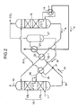
- Fig. 2 is a schematic of a CO 2 recovery system according to a first comparative embodiment. Components the same as those of the CO 2 recovery system according to the first embodiment are assigned with the same reference numerals, and explanation thereof is omitted. As show in Fig.
- the CO 2 recovery system according to the first comparative embodiment further includes, in addition to the configuration of the first embodiment, a branching node 24 provided in the rich-solution supply line 20 that branches the rich solution 14 into the first rich-solution supply line 20-1 and the second rich-solution supply line 20-2; the steam-condensate heat exchanger 21 that is provided in the first rich-solution supply line 20-1 and heats the rich solution 14; a flash drum 27 provided in the downstream side of the steam-condensate heat exchanger 21; and a semi-lean-solution heat exchanger 29 that is provided in the second rich-solution supply line 20-2 and heats the rich solution 14 with the residual heat of a semi-lean solution 28 obtained by removing part of CO 2 from the rich solution in the flash drum 27.
- a branching node 24 provided in the rich-solution supply line 20 that branches the rich solution 14 into the first rich-solution supply line 20-1 and the second rich-solution supply line 20-2
- the steam-condensate heat exchanger 21 that is provided in the first rich-solution supply
- An end of a semi-lean-solution supply line 30 for supplying the semi-lean solution 28 is connected to a middle stage portion of the absorption tower 13.
- the second rich-solution supply line 20-2 is connected near the upper stage of the regeneration tower 15, and CO 2 is removed and recovered in the regeneration tower 15.
- the steam-condensate heat exchanger 21 heats the rich solution 14 with the residual heat of the steam condensate 19 fed from the regeneration heater 18, in which the rich solution is heated with the residual heat of the steam condensate, therefore, the residual heat of the steam condensate 19 having been used in the regeneration heater 18 is effectively used.
- the rich solution 14 heated with the residual heat is introduced into the flash drum 27. Then, the rich solution 14 is caused to flash in the flash drum 27 to enable improvement of CO 2 removal efficiency.
- the rich solution 14 is heat-exchanged with the residual heat of the semi-lean solution 28 obtained by removing part of CO 2 from the rich solution and fed from the flash drum 27, in the semi-lean-solution heat exchanger 29 interposed in the second rich-solution supply line 20-2 branched. Therefore, it is possible to increase the temperature of the rich solution 14 to be introduced into the regeneration tower 15, and as a result, the supply amount of steam to be used in the regeneration tower 15 can be reduced.
- Most of CO 2 is removed from the semi-lean solution 28, obtained by removing part of CO 2 from the rich solution, in the flash drum 27. Therefore, by supplying this semi-lean solution 28 to the middle stage portion of the absorption tower 13, CO 2 is absorbed without being regenerated in the regeneration tower 15. Furthermore, CO 2 removed in the flash drum 27 joins CO 2 fed from the regeneration tower 15, to be recovered separately.
- the ratio of division of the rich solution 14 into the first rich-solution supply line 20-1 and the second rich-solution supply line 20-2 at the branching node 24 is simply set to a range from 30:70 to 70:30, preferably 50:50.
- the first comparative embodiment is configured to further divide the inner side of the absorption tower 13 into two stages: an upper-stage filling layer 13-U and a lower-stage filling layer 13-L; to extract the absorbing solution 12 having absorbed CO 2 , from the upper-stage filling layer 13-U to the outside; and to mix the absorbing solution 12 with the semi-lean solution 28 to be cooled.
- This is because it is preferable to decrease the temperature of a solution to be supplied because the absorption reaction is an exothermic reaction. In this embodiment, the temperature is decreased to about 40°C to 50°C.
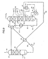
- Fig. 3 is a schematic of a CO 2 recovery system according to a second comparative embodiment. Components the same as those in each of the CO 2 recovery systems according to the first and the first comparative embodiments are assigned with the same reference numerals, and explanation thereof is omitted. As shown in Fig.
- the CO 2 recovery system further includes, in addition to the configuration of the first embodiment, the branching node 24 provided in the rich-solution supply line 20 and divides the rich solution 14 into the first rich-solution supply line 20-1 and the second rich-solution supply line 20-2; a steam-condensate heat exchanger 31 that is provided in an end of the first rich-solution supply line 20-1 and causes the rich solution 14 to flash; and the semi-lean-solution heat exchanger 29 that is provided in the second rich-solution supply line 20-2 and heats the rich solution 14 with the residual heat of the semi-lean solution 28 obtained by removing part of CO 2 from the rich solution in the steam-condensate heat exchanger 31.
- the end of the semi-lean-solution supply line 30 for supplying the semi-lean solution 28 is connected to the middle stage portion of the absorption tower 13.
- the steam-condensate heat exchanger 31 is not an exchanger such as the plate heat exchanger, but includes, as shown in Fig. 3 , a first flash drum 33 in which a flash portion 32, for causing the rich solution 14 to flash, is provided in its upper side; a filling layer 34 provided in the first flash drum 33; and a steam supply portion 36 that is provided in the lower-portion of the flash drum and supplies steam 35 from the steam condensate 19. If the steam condensate 19 is pressurized saturated steam, a second flash drum 37 is provided to make it as atmospheric pressure steam 35, and the steam 35 is supplied to the first flash drum 33, where CO 2 is removed from the rich solution 14 using the heat of the steam 35.
- the semi-lean-solution heat exchanger 29 heats the rich solution 14 using the residual heat of the semi-lean solution 28 obtained by removing part of CO 2 from the rich solution in the first flash drum 33, and then, the rich solution is supplied to the middle stage portion of the absorption tower 13.
- the steam-condensate heat exchanger 31 heats the rich solution 14 in the first rich-solution supply line 20-1, with the residual heat of the steam condensate 19 fec from the regeneration heater 18, in which the rich solution is heated with the steam 35. Therefore, the residual heat of the steam condensate 19 having been used in the regeneration heater 18 is effectively used.
- the rich solution 14 is heat-exchanged using the residual heat of the semi-lean solution 28 obtained by removing CO 2 by flash in the steam-condensate heat exchanger 31, in the semi-lean-solution heat exchanger 29 interposed in the second rich-solution supply line 20-2 branched.
- the first flash drum 33 functions as an auxiliary regeneration tower for the regeneration tower 15.
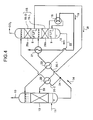
- Fig. 4 is a schematic of a CO 2 recovery system according to a second and third embodiment. Components the same as those in each of the CO 2 recovery systems according to the preceding embodiments are assigned with the same reference numerals, and explanation thereof is omitted. As shown in Fig.
- the CO 2 recovery system according to the second and third embodiment of the present invention further includes, in addition to the configuration of the first embodiment, an upper-portion regeneration tower 15-U and a lower-portion regeneration tower 15-L into which the inner side of the regeneration tower 15 is vertically divided; the branching node 24 provided in the rich-solution supply line 20 and dividing the rich solution 14; the steam-condensate heat exchanger 21 interposed in the first rich-solution supply line 20-1 branched; and the semi-lean-solution heat exchanger 29 that is provided in the second rich-solution supply line 20-2, and heats the rich solution 14 with the residual heat of the semi-lean solution 28 obtained by removing part of CO 2 from the rich solution in the upper-portion regeneration tower 15-U.
- the end of the first rich-solution supply line 20-1 is connected to the lower-portion regeneration tower 15-L
- the end of the second rich-solution supply line 20-2 is connected to the upper-portion regeneration tower 15-U
- the end of the semi-lean-solution supply line 30 for supplying the semi-lean solution 28 is connected to the middle stage portion of the absorption tower 13.
- the second and third embodiment is configured to provide the steam-condensate heat exchanger 21 that heats the rich solution 14 with the residual heat of the steam condensate 19 fed from the regeneration heater 18, in which the rich solution is heated with the residual heat of the steam condensate. Therefore, the residual heat of the steam condensate 19 having been used in the regeneration heater 18 is effectively used. Furthermore, the rich solution 14 heated with the residual heat is introduced into the lower-portion regeneration tower 15-L, where it is regenerated.
- the semi-lean solution 28, obtained by removing part of CO 2 from the rich solution 14 in the upper-portion regeneration tower 15-U, is extracted to the outside through the semi-lean-solution supply line 30, and the rich solution 14 is heat-exchanged with the residual heat of the semi-lean solution in the semi-lean-solution heat exchanger 29 interposed in the second rich-solution supply line 20-2 branched. Therefore, it is possible to increase the temperature of the rich solution 14 to be introduced into the regeneration tower 15, and as a result, the supply amount of steam to be used in the regeneration tower 15 can be reduced.
- the ratio of division of the rich solution 14 into the first rich-solution supply line 20-1 and the second rich-solution supply line 20-2 at the branching node 24 is simply set to a range from 25:75 to 75:25.
- Fig. 5 is a schematic of a CO 2 recovery system according to a fourth embodiment. Components the same as those in each of the CO 2 recovery systems according to the preceding embodiments are assigned with the same reference numerals, and explanation thereof is omitted. As shown in Fig.
- the CO 2 recovery system includes the upper-portion regeneration tower 15-U, a middle-portion regeneration tower 15-M, and the lower-portion regeneration tower 15-L, which are obtained by dividing the regeneration tower 15 into three: upper, middle, and lower portions; the branching node 24 provided in the rich-solution supply line 20 and dividing the rich solution 14; the lean-solution heat exchanger 23 interposed in the first rich-solution supply line 20-1 branched; the semi-lean-solution heat exchanger 29 that is provided in the second rich-solution supply line 20-2, and heats the rich solution with the residual heat of the semi-lean solution 28 obtained by removing part of CO 2 from the rich solution in the upper-portion regeneration tower 15-U; and the steam-condensate heat exchanger 21 that extracts the semi-lean solution 28 obtained by removing part of CO 2 from the rich solution in the middle-portion degeneration tower 15-M, to the outside of the regeneration tower through an extraction line 41, and that heats the semi-lean solution 28
- the end of the first rich-solution supply line 20-1 is connected to the middle-portion regeneration tower 15-M
- the end of the second rich-solution supply line 20-2 is connected to the upper-portion regeneration tower 15-U
- the extraction line 41 is connected to the lower-portion regeneration tower 15-L
- the end of the supply line 30 for supplying the semi-lean solution 28 is connected to the middle stage portion of the absorption tower 13.
- the fourth embodiment is configured to provide the steam-condensate heat exchanger 21 that heats the semi-lean solution 28 extracted through the extraction line 41, in which the semi-lean solution 28 is heated with the residual heat of the steam condensate 19. Therefore, the residual heat of the steam condensate 19 having been used in the regeneration heater 18 is effectively used, and as a result, the supply amount of steam to be used in the regeneration tower 15 can be reduced.
- the rich solution 14 is heat-exchanged, using the lean solution 16 regenerated in the regeneration tower 15, in the lean-solution heat exchanger 23 interposed in the first rich-solution supply line 20-1, and the rich solution 14 heated with the residual heat is introduced into the middle-portion regeneration tower 15-M, which allows reduction in the supply amount of steam to be used in the regeneration tower.
- the semi-lean solution 28, obtained by removing part of CO 2 from the rich solution in the upper-portion regeneration tower 15-U, is extracted to the outside through the semi-lean-solution supply line 30, and the rich solution 14 is heat-exchanged with the residual heat of the semi-lean solution 28 in the semi-lean-solution heat exchanger 29 interposed in the second rich-solution supply line 20-2 branched. Therefore, it is possible to increase the temperature of the rich solution 14 to be introduced into the upper-portion regeneration tower 15-U, and as a result, the supply amount of steam to be used in the regeneration tower 15 can be reduced.
- the ratio of division of the rich solution 14 into the first rich-solution supply line 20-1 and the second rich-solution supply line 20-2 at the branching node 24 is simply set to a range from 25:75 to 75:25.
- Fig. 6 is a schematic of a CO 2 recovery system according to a fifth embodiment. Components the same as those in each of the CO 2 recovery systems according to the preceding embodiments are assigned with the same reference numerals, and explanation thereof is omitted. As shown in Fig.
- the CO 2 recovery system includes the upper-portion regeneration tower 15-U and the lower-portion regeneration tower 15-L, which are obtained by dividing the regeneration tower at least into two portions; and the steam-condensate heat exchanger 21 that heats the semi-lean solution 28, obtained by removing part of CO 2 from the rich solution, with the residual heat of the steam condensate, the semi-lean solution 28 having been extracted from the upper-portion regeneration tower 15-U through the extraction pipe 41. And the semi-lean solution 28 heated is supplied to the lower-portion regeneration tower 15-L.
- the fifth embodiment is configured to provide the steam-condensate heat exchanger 21 that heats the semi-lean solution 28 extracted through the extraction line 41, with the residual heat of the steam condensate 19 fed from the regeneration heater 18, in which the semi-lean solution 28 is heated with the residual heat of the steam condensate. Therefore, the residual heat of the steam condensate 19 having been used in the regeneration heater 18 is effectively used, and as a result, the supply amount of steam to be used in the regeneration tower 15 can be reduced.
- Fig. 7 is a schematic of a CO 2 recovery system according to a sixth embodiment. Components the same as those in each of the CO 2 recovery systems according to the preceding embodiments are assigned with the same reference numerals, and explanation thereof is omitted. As shown in Fig.
- the CO 2 recovery system includes, in addition to the system of the fifth embodiment, a first branching node 24-1 provided in the rich-solution supply line 20 and dividing the rich solution 14; a first lean-solution heat exchanger 23-1 interposed in the first rich-solution supply line 20-1 branched at the first branching node 24-1; the semi-lean-solution heat exchanger 29 that is provided in the second rich-solution supply line 20-2 branched at the first branching node 24-1, and heats the rich solution 14 with the residual heat of the semi-lean solution 28 obtained by removing part of CO 2 from the rich solution in the upper-portion regeneration tower 15-U; a second lean-solution heat exchanger 23-2 in which the rich solution 14 joined at a joint 42 between the first rich-solution supply line 20-1 and the second rich-solution supply line 20-2, is heat-exchanged after the heat exchange in the semi-lean-solution heat exchanger 29; a second branching node 24-2 provided in the downstream side of the semi-lean-solution heat exchanger 29;
- first semi-lean-solution supply line 30-1 is connected to the lower-portion regeneration tower 15-L, and the end of a second semi-lean-solution supply line 30-2 branched at the second branching node 24-2 is connected to the middle stage portion of the absorption tower 13.
- the semi-lean-solution heat exchanger 29 uses the residual heat of the semi-lean solution 28 extracted from the upper-portion regeneration tower 15-U to heat the rich solution 14, and the residual heat of the semi-lean solution 28 is thereby effectively used.
- the steam-condensate heat exchanger 21 is provided in the way in which part of the semi-lean solution 28 is returned again to the lower-portion regeneration tower 15-L through the first semi-lean-solution supply line 30-1, the semi-lean solution 28 can be heated with the residual heat of the steam condensate 19.
- the residual heat of the steam condensate 19 having been used in the regeneration heater 18 is thereby effectively used, and as a result, the supply amount of steam to be used in the regeneration tower 15 can be reduced.
- One part of the rich solution 14 once divided is heat-exchanged in the semi-lean-solution heat exchanger 29, and the other part of the rich solution 14 divided is also heat-exchanged in the first lean-solution heat exchanger 23-1, and these parts of the rich solution 14 are jointed at the joint 42, and are further heat-exchanged in the second lean-solution heat exchanger 23-2, to be supplied to the upper-portion regeneration tower 15-U.
- the temperature of the rich solution 14 to be introduced into the regeneration tower thereby increases, and as a result, the supply amount of steam to be used in the regeneration tower 15 can be reduced.
- Fig. 8 is a schematic of a CO 2 recovery system according to an seventh and eighth embodiment. Components the same as those in each of the CO 2 recovery systems according to the preceding embodiments are assigned with the same reference numerals, and explanation thereof is omitted. As shown in Fig.
- the CO 2 recovery system includes the upper-portion regeneration tower 15-U and the lower-portion regeneration tower 15-L, which are obtained by dividing the regeneration tower at least into two portions; the first lean-solution heat exchanger 23-1 that is interposed in the extraction line 41 for extracting the semi-lean solution 28, obtained by removing part of CO 2 from the rich solution, from the upper-portion regeneration tower 15-U divided, and heats the semi-lean solution 28 with the residual heat of the lean solution 16 that flows through the lean-solution supply line 22; and the steam-condensate heat exchanger 21 that is provided in the downstream side of and adjacent to the first lean-solution heat exchanger 23-1 in the extraction line 41, and reheats the semi-lean solution 28 having been heated once, with the steam condensate 19.
- the second lean-solution heat exchanger 23-2 which heats the rich solution 14 with the residual heat of the lean solution after the semi-lean solution 28 is heated, is provided in the rich-solution supply line
- the semi-lean solution 28 extracted from the upper-portion regeneration tower 15-U is heated in the first lean-solution heat exchanger 23-1, and further heated in the steam-condensate heat exchanger 21, and the residual heat of the steam condensate 19 having been used in the regeneration heater 18 is thereby effectively used.
- the supply amount of steam to be used in the regeneration tower 15 can be reduced.
- the inside of the regeneration tower is divided into a plurality of stages and the semi-lean solution 28, extracted from each stage of the regeneration tower divided, is returned to the regeneration tower on the lower stage side, the semi-lean solution 28 is heat-exchanged in the lean-solution heat exchanger and the steam-condensate heat exchanger respectively.
- This causes the temperature of the semi-lean solution 28, which is regenerated in the regeneration tower 15, to be increased, and consequently, the supply amount of steam to be used in the regeneration tower 15 can be reduced.
- Fig. 9 is a schematic of a CO 2 recovery system according to a ninth embodiment. Components the same as those in each of the CO 2 recovery systems according to the preceding embodiments are assigned with the same reference numerals, and explanation thereof is omitted. As shown in Fig.
- the CO 2 recovery system includes the upper-portion regeneration tower 15-U, the middle-portion regeneration tower 15-M, and the lower-portion regeneration tower 15-L, which are obtained by dividing the regeneration tower 15 into three: upper, middle, and lower portions; the first lean-solution heat exchanger 23-1 that heats the semi-lean solution 28, obtained by removing part of CO 2 from the rich solution and extracted from the upper-portion regeneration tower 15-U through a first extraction pipe 41-1, with the lean solution fed from the regeneration tower; the steam-condensate heat exchanger 21 that heats the semi-lean solution 28, obtained by removing part of CO 2 from the rich solution and extracted from the middle-portion regeneration tower 15-M through a second extraction pipe 41-2, with the steam condensate; the semi-lean-solution heat exchanger 29 that is provided in the rich-solution supply line 20, and heats the rich solution 14 with the part of the semi-lean solution 28 extracted from the middle-portion regeneration tower 15-M; and the second lean-
- the semi-lean solution heated is supplied to the lower stage side of the regeneration tower, and the semi-lean solution 28 after heat exchange is performed in the semi-lean-solution heat exchanger 29 is supplied to the middle stage portion of the absorption tower 13 through the semi-lean-solution supply pipe 30.
- the semi-lean solution 28 respectively extracted from the upper-portion regeneration tower 15-U and the middle-portion regeneration tower 15-M is heated in the first lean-solution heat exchanger 23-1 or in the steam-condensate heat exchanger 21, and the residual heat of the lean solution 16 and of the steam condensate 19 is thereby effectively used.
- the supply amount of steam to be used in the regeneration tower 15 can be reduced.
- the residual heat of the semi-lean solution 28 after heat exchange is performed in the steam-condensate heat exchanger 21 is used for heating the rich solution
- the residual heat of the lean solution heat-exchanged in the first lean-solution heat exchanger 23-1 is used for heating the rich solution in the second lean-solution heat exchanger 23-2. It is thereby possible to increase the temperature of the rich solution 14 to be supplied to the regeneration tower 15, and as a result, the supply amount of steam to be used in the regeneration tower 15 can be reduced.
- FIG. 10 is a schematic of the CO 2 recovery system according to example 1.
- the CO 2 -containing exhaust gas 11 supplied to the CO 2 absorption tower 13 is brought into countercurrent contact with the absorbing solution 12 in a filling portion, the absorbing solution 12 having predetermined concentration and being supplied from the nozzle 8.
- CO 2 in the combustion exhaust gas is absorbed and removed by the CO 2 -absorbing solution 12, and the remaining CO 2 -removed exhaust gas 10, from which CO 2 has been absorbed and removed, is fed to the outside.
- the absorbing solution 12 supplied to the CO 2 absorption tower 13 absorbs CO 2 , and reaction heat due to the absorption causes the temperature of the absorbing solution 12 to become higher than normal temperature in a tower head.
- the absorbing solution having absorbed CO 2 is sent by a discharge pump 51 for the absorbing solution, as the rich solution 14, to the lean-solution heat exchanger 23 and the steam-condensate heat exchanger 21, where it is heated, to be introduced into the regeneration tower 15.
- the absorbing solution is regenerated by being heated with the steam 17 by the regeneration heater 18, cooled as the lean solution 16 by the lean-solution heat exchanger 23 and a cooler 52 provided as necessary, and is returned to the CO 2 absorption tower 13.
- CO 2 separated from the absorbing solution is cooled by a regeneration-tower reflux condenser 53, the steam associated with CO 2 is separated from condensed reflux water in a CO 2 separator 54, and output to the outside of the system through a recovered-CO 2 discharge line 55.
- Reflux water 56 is flowed back to the regeneration tower 15 by a reflux pump 57.
- the steam used in the regeneration heater 18 is introduced into a separator to be flashed, and the residual heat of the steam flashed as the steam condensate 19 is used for heating the rich solution 14 in the steam-condensate heat exchanger 21.
- the amount of steam consumed in the comparative example of Fig. 22 was 98.77 MMkcal/h. Assuming the comparative example is 100, the amount of steam consumed in this example becomes 99.2%. Therefore, the reduction rate of specific steam consumption (improvement effect) was 0.8%.
- FIG. 11 is a schematic of the CO 2 recovery system according to example 2. Components the same as those of example 1 are assigned with the same reference numerals and explanation thereof is omitted.
- a flash drum 61 is provided in the downstream side of the steam-condensate heat exchanger 21 that heats the rich solution 14. In the upstream side of the flash drum 61, the rich solution 14 is heated in the steam-condensate heat exchanger 21, and therefore, CO 2 in the rich solution 14 can be removed in the flash drum 61.
- the temperature of the rich solution fed from the flash drum 61 is 103.9°C, but because part of CO 2 has been removed, decreasing inlet temperature of the regeneration tower 15 causes the steam discharged from the tower head to be reduced, which is preferable.
- the amount of steam consumed in the regeneration tower 15 became 97.64 MMkcal/h. Assuming the comparative example is 100, the amount of steam consumed in this example becomes 98.9%. Therefore, the reduction rate of specific steam consumption (improvement effect) was 1.1%.
- FIG. 12 is a schematic of the CO 2 recovery system according to example 3. Components the same as those of example 1 are assigned with the same reference numerals and explanation thereof is omitted.
- the flash drum 61 is provided in the upstream side of the steam-condensate heat exchanger 21 that heats the rich solution 14.
- the rich solution 14 was heated in the steam-condensate heat exchanger 21, to thereby increase the temperature of the rich solution 14 to be supplied to the regeneration tower 15.
- the amount of steam consumed in the regeneration tower 15 became 97.27 MMkcal/h. Assuming the comparative example is 100, the amount of steam consumed in this example becomes 98.5%. Therefore, the reduction rate of specific steam consumption (improvement effect) was 1.5%.
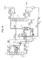
- FIG. 13 is a schematic of the CO 2 recovery system according to example 4. Components the same as those of example 1 are assigned with the same reference numerals and explanation thereof is omitted.
- the rich solution 14 was divided, part of the rich solution 14 divided was sent to the heat exchanger 31 of flash drum type, where the rich solution 14 was heat-exchanged with the steam from the steam condensate and CO 2 was removed from the rich solution 14.
- the other part of the rich solution 14 divided was hear-exchanged in the semi-lean-solution heat exchanger 29, to increase the temperature of the rich solution 14 to be supplied to the regeneration tower 15.
- Fig. 14 is a schematic of the CO 2 recovery system according to example 5. Components the same as those of example 1 are assigned with the same reference numerals and explanation thereof is omitted.
- the rich solution 14 was divided, and part of the rich solution 14 divided was sent to the heat exchanger 31 of flash drum type, but on the way to the heat exchanger 31, the rich solution 14 was heat-exchanged with the residual heat of the steam condensate in the steam-condensate heat exchanger 21, to improve the removal rate of CO 2 from the rich solution 14 in the flash drum 31.
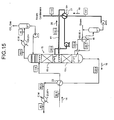
- FIG. 15 is a schematic of the CO 2 recovery system according to example 6. Components the same as those of example 1 are assigned with the same reference numerals and explanation thereof is omitted.
- the regeneration tower 15 was divided into two portions, the semi-lean solution 28 extracted from the upper-portion regeneration tower 15-U was heat-exchanged with the residual heat of the steam condensate 19 in the steam-condensate heat exchanger 21, and the semi-lean solution 28 heat-exchanged was returned to the lower-portion regeneration tower 15-L. This caused an increase in the temperature of the semi-lean solution to be supplied to the lower portion side of the regeneration tower 15.
- FIG. 16 is a schematic of the CO 2 recovery system according to example 7. Components the same as those of example 1 are assigned with the same reference numerals and explanation thereof is omitted.
- the regeneration tower 15 was divided into two portions, and the rich solution 14 was divided.
- the lean-solution heat exchanger 23 was provided in the first rich-solution supply line 20-1, and in the downstream side thereof, the steam-condensate heat exchanger 21 was provided, to thereby increase the temperature of the rich solution 14 to be supplied to the lower-portion regeneration tower 15-L.
- the ratio of division of the rich solution 14 is such that the first rich solution was set to 70% and the second rich solution was set to 30%.
- the amount of steam consumed in the regeneration tower 15 became 93.58 MMkcal/h.
- the comparative example is 100, the amount of steam consumed in this example becomes 94.8%. Therefore, the reduction rate of specific steam consumption (improvement effect) was 5.2%.
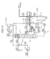
- FIG. 17 is a schematic of the CO 2 recovery system according to example 8. Components the same as those of example 1 are assigned with the same reference numerals and explanation thereof is omitted.
- the regeneration tower 15 was divided into two portions, and the semi-lean solution 28 extracted from the upper-portion regeneration tower 15-U was first heat-exchanged in the first lean-solution heat exchanger 23-1, and then, was heat-exchanged with the residual heat of the steam condensate 19 in the steam-condensate heat exchanger 21, and the semi-lean solution 28 heat-exchanged was returned to the lower-portion regeneration tower 15-L.
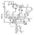
- FIG. 18 is a schematic of the CO 2 recovery system according to example 9. Components the same as those of example 1 are assigned with the same reference numerals and explanation thereof is omitted.
- the regeneration tower 15 was divided into four portions such as a first regeneration tower 15-1, a second regeneration tower 15-2, a third regeneration tower 15-3, and a fourth regeneration tower 15-4.
- the semi-lean solution 28 respectively extracted from the first regeneration tower 15-1 and the third regeneration tower 15-3 was heat-exchanged with the respective residual heat of the steam condensate in a first steam-condensate heat exchanger 21-1 and a second steam-condensate heat exchanger 21-2, respectively. Because the temperature in the lower portion side of the regeneration tower was high, the residual heat of the steam condensate 19 was effectively used.
- the semi-lean solution extracted from the second regeneration tower 15-2 was heat-exchanged with the residual heat of the lean solution 16 in the first lean-solution heat exchanger 23-1.
- the rich solution 14 fed from the absorption tower 13 was heat-exchanged in a third lean-solution heat exchanger 23-3.
- FIG. 19 is a schematic of the CO 2 recovery system according to example 10. Components the same as those of example 1 are assigned with the same reference numerals and explanation thereof is omitted.
- the regeneration tower 15 was divided into three portions such as the upper-portion regeneration tower 15-U, the middle-portion regeneration tower 15-M, and the lower-portion regeneration tower 15-L.
- the semi-lean solution 28 extracted from the middle-portion regeneration tower 15-M was heat-exchanged with the residual heat of the steam condensate in the steam-condensate heat exchanger 21.
- Part of the semi-lean solution 28 extracted was supplied to the semi-lean-solution heat exchanger 29 that heats the rich solution 14, where the residual heat of the semi-lean solution was effectively used. Furthermore, the semi-lean solution 28 extracted from the upper-portion regeneration tower 15-U was heat-exchanged with the residual heat of the lean solution 16 in the first lean-solution heat exchanger 23-1.
- the rich solution 14 heat-exchanged in the semi-lean-solution heat exchanger 29 was heat-exchanged in the second lean-solution heat exchanger 23-2 in which the rich solution 14 was heat-exchanged with the residual heat of the lean solution 16 that had been heat-exchanged in the first lean-solution heat exchanger 23-1.
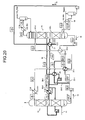
- FIG. 20 is a schematic of the CO 2 recovery system according to example 11. Components the same as those of example 1 are assigned with the same reference numerals and explanation thereof is omitted.
- the regeneration tower 15 was divided into two portions such as the upper-portion regeneration tower 15-U and the lower-portion regeneration tower 15-L.
- the semi-lean solution 28, extracted from the upper-portion regeneration tower 15-U, was used to heat the rich solution in the second rich-solution supply line 20-2, in the semi-lean-solution heat exchanger 29.
- the semi-lean solution 28 was divided, to be heat-exchanged with the residual heat of the steam condensate in the steam-condensate heat exchanger 21 before being supplied to the lower-portion regeneration tower 15-L.
- the rich solution in the first rich-solution supply line 20-1 was heat-exchanged in the first lean-solution heat exchanger 23-1, was jointed with the other one to be heat-exchanged with the residual heat of the lean solution 16 in the second lean-solution heat exchanger 23-2, and was supplied to the regeneration tower 15.
- the amount of steam consumed in the regeneration tower 15 became 93.96 MMkcal/h.
- the comparative example is 100, the amount of steam consumed in this example becomes 95.1%. Therefore, the reduction rate of specific steam consumption (improvement effect) was 4.9%.
- FIG. 21 is a schematic of the CO 2 recovery system according to example 12. Components the same as those of example 1 are assigned with the same reference numerals and explanation thereof is omitted.
- the regeneration tower 15 was divided into three portions such as the upper-portion regeneration tower 15-U, the middle-portion regeneration tower 15-M, and the lower-portion regeneration tower 15-L.
- the semi-lean solution 28 extracted from the middle-portion regeneration tower 15-M was heat-exchanged with the residual heat of the steam condensate in the steam-condensate heat exchanger 21.
- the rich solution 14 was divided, and the lean-solution heat exchanger 23 was provided in the first rich-solution supply line 20-1.
- the semi-lean-solution heat exchanger 29 was provided in the second rich-solution supply line 20-2 where heat exchange was performed using the semi-lean solution 28 extracted from the upper-portion regeneration tower 15-U, so that the residual heat of the semi-lean solution was effectively used.
- the amount of steam consumed in the regeneration tower 15 became 91.14 MMkcal/h.
- the comparative example is 100
- the amount of steam consumed in this example becomes 92.3%. Therefore, the reduction rate of specific steam consumption (improvement effect) was 7.7%.
- the CO 2 recovery system according to the present invention is suitable for reduction in the supply amount of heated steam used in the regeneration tower by effectively using the residual heat of the steam condensate and the residual heat of the semi-lean solution.
Landscapes
- Chemical & Material Sciences (AREA)
- Engineering & Computer Science (AREA)
- Analytical Chemistry (AREA)
- General Chemical & Material Sciences (AREA)
- Oil, Petroleum & Natural Gas (AREA)
- Chemical Kinetics & Catalysis (AREA)
- Health & Medical Sciences (AREA)
- Biomedical Technology (AREA)
- Environmental & Geological Engineering (AREA)
- Gas Separation By Absorption (AREA)
- Treating Waste Gases (AREA)
- Electrical Discharge Machining, Electrochemical Machining, And Combined Machining (AREA)
- Purification Treatments By Anaerobic Or Anaerobic And Aerobic Bacteria Or Animals (AREA)
Claims (12)
- CO2-Rückgewinnungssystem, welches einen Absorptionsturm (13), der CO2-haltiges Gas mit einer CO2-absorbierenden Lösung in Kontakt bringt, um CO2 zu entfernen, und einen Regenerationsturm (15), der eine reiche Lösung, die CO2 absorbiert hat, regeneriert, enthält und welches eine magere Lösung, die durch Entfernen von CO2 aus der reichen Lösung in dem Regenerationsturm erhalten wird, in dem Absorptionsturm wiederverwendet und umfasst:eine Regenerationsheizvorrichtung (18), welche die in der Nähe eines unteren Bereichs des Regenerationsturms (15) wiedergewonnene magere Lösung nach außen entnimmt und einen Wärmeaustausch der mageren Lösung mit gesättigtem Dampf durchführt; undeinen Dampf-Kondensat-Wärmetauscher (21), der die reiche Lösung, die dem Regenerationsturm (15) zuzuführen ist, erwärmt, oder eine halb-magere Lösung, die durch Entfernen eines Teils des CO2 aus der reichen Lösung erhalten wird, mit der Restwärme des Dampfkondensats, das aus der Regenerationsheizvorrichtung eingespeist wird, erwärmt, wobei die halb-magere Lösung aus einem mittleren Bereich des Regenerationsturms entnommen worden ist.
- CO2-Rückgewinnungssystem gemäß Anspruch 1, wobei der Regenerationsturm (15) einen oberen Regenerationsturmbereich (15-U) und einen unteren Regenerationsturmbereich (15-L) enthält und das CO2-Rückgewinnungssystem weiterhin umfasst:eine Versorgungsleitung für die reiche Lösung (20), welche die reiche Lösung von dem Absorptionsturm (13) zu dem Regenerationsturm (15) befördert;einen Verzweigungsknoten (24), der sich in der Versorgungsleitung für die reiche Lösung (20) befindet und der die Versorgungsleitung für die reiche Lösung (20) in eine erste Versorgungsleitung für die reiche Lösung (20-1) und eine zweite Versorgungsleitung für die reiche Lösung (20-2) verzweigt, wobei der Dampf-Kondensat-Wärmetauscher (21) sich in der ersten Versorgungsleitung für die reiche Lösung (20-1) befindet und die reiche Lösung in der ersten Versorgungsleitung für die reiche Lösung (20-1) mit dem Dampfkondensat erwärmt;eine Versorgungsleitung für die halbmagere Lösung (30), die die halbmagere Lösung aus dem oberen Regenerationsturmbereich (15-U) entnimmt und die entnommene halbmagere Lösung zu einem mittleren Abschnittsbereich des Absorptionsturms (13) befördert;einen Wärmetauscher für die halbmagere Lösung (29), der sich in der zweiten Versorgungsleitung für die reiche Lösung (20-2) und der Versorgungsleitung für die halbmagere Lösung (30) befindet und die reiche Lösung in der zweiten Versorgungsleitung für die reiche Lösung (20-2) mit der halbmageren Lösung (28) in der Versorgungsleitung für die halbmagere Lösung (30) erwärmt,wobeiein Ende der ersten Versorgungsleitung für die reiche Lösung (20-1) mit dem unteren Regenerationsturmbereich (15-L) verbunden ist undein Ende der zweiten Versorgungsleitung für die reiche Lösung (20-2) mit dem oberen Regenerationsturmbereich (15-U) verbunden ist.
- CO2-Rückgewinnungssystem gemäß Anspruch 1, welches weiterhin umfasst:eine Versorgungsleitung für die reiche Lösung (20), welche die reiche Lösung von dem Absorptionsturm (13) zu dem Regenerationsturm (15) befördert;eine Versorgungsleitung für die magere Lösung (22), welche die magere Lösung dem Regenerationsturm (15) entnimmt und die entnommene magere Lösung zu dem Absorptionsturm (13) befördert; undeinen Wärmetauscher für die magere Lösung (23), der zwischen der Versorgungsleitung für die reiche Lösung (20) und der Versorgungsleitung für die magere Lösung (22) angeordnet ist und die reiche Lösung in der Versorgungsleitung für die reiche Lösung (20) mit der mageren Lösung in der Versorgungsleitung für die magere Lösung (22) erwärmt.
- CO2-Rückgewinnungssystem gemäß Anspruch 1, wobei der Regenerationsturm (15) einen oberen Regenerationsturmbereich (15-U), einen mittleren Regenerationsturmbereich (15-M) und einen unteren Regenerationsturmbereich (15-L) enthält und das CO2-Rückgewinnungssystem weiterhin umfasst:eine Versorgungsleitung für die reiche Lösung (20), welche die reiche Lösung von dem Absorptionsturm (13) zu dem Regenerationsturm (15) befördert;einen Verzweigungsknoten (24), der sich in der Versorgungsleitung für die reiche Lösung (20) befindet und der die Versorgungsleitung für die reiche Lösung (20) in eine erste Versorgungsleitung für die reiche Lösung (20-1) und eine zweite Versorgungsleitung für die reiche Lösung (20-2) verzweigt;einen Wärmetauscher für die magere Lösung (23), der sich in der ersten Versorgungsleitung für die reiche Lösung (20-1) befindet und die reiche Lösung mit der mageren Lösung, die in dem Regenerationsturm (15) hergestellt wurde, erwärmt;eine Versorgungsleitung für die halbmagere Lösung (30), welche die halbmagere Lösung aus dem oberen Regenerationsturmbereich (15-U) entnimmt und die entnommen halbmagere Lösung zu einem mittleren Abschnittsbereich des Absorptionsturms (13) befördert;einen Wärmetauscher für die halbmagere Lösung (29), der sich in der zweiten Versorgungsleitung für die reiche Lösung (20-2) und der Versorgungsleitung für die halbmagere Lösung (30) befindet und die reiche Lösung in der zweiten Versorgungsleitung für die reiche Lösung (20-2) mit der halbmageren Lösung in der Versorgungsleitung für die halbmagere Lösung (30) erwärmt;eine mittlere Entnahmeleitung für die halbmagere Lösung (41), welche die halbmagere Lösung von einem dritten Punkt des mittleren Regenerationsturmbereichs (15-M) entnimmt und die entnommene halbmagere Lösung zu einem vierten Punkt des mittleren Regenerationsturmbereichs (15-M), der dem dritten Punkt nachgeschaltet ist, zurückführt, wobeider Dampf-Kondensat-Wärmetauscher (21) in der mittleren Entnahmeleitung für die halbmagere Lösung (41) angeordnet ist und die halbmagere Lösung in der mittleren Entnahmeleitung für die halbmagere Lösung (41) mit Dampfkondensat erwärmt,ein Ende der ersten Versorgungsleitung für die reiche Lösung (20-1) mit dem mittleren Regenerationsturmbereich (15-M) verbunden ist undein Ende der Versorgungsleitung für die halbmagere Lösung (30) mit dem mittleren Abschnittsbereich des Absorptionsturms (13) verbunden ist.
- CO2-Rückgewinnungssystem gemäß Anspruch 1, wobei der Regenerationsturm (15) einen oberen Regenerationsturmbereich (15-U) und einen unteren Regenerationsturmbereich (15-L) enthält und das CO2-Rückgewinnungssystem weiterhin umfasst:eine obere Entnahmeleitung für die halbmagere Lösung (41), welche die halbmagere Lösung von einem siebten Punkt des oberen Regenerationsturmbereichs (15-U) entnimmt und die entnommene halbmagere Lösung zu einem achten Punkt des oberen Regenerationsturmbereichs (15-U), der dem siebten Punkt nachgeschaltet ist, zurückführt, wobeider Dampf-Kondensat-Wärmetauscher (21) in der oberen Entnahmeleitung für die halbmagere Lösung (41) angeordnet ist und die halbmagere Lösung in der oberen Entnahmeleitung für die halbmagere Lösung (41) mit dem Dampfkondensat erwärmt;eine Versorgungsleitung für die reiche Lösung (20), welche die reiche Lösung von dem Absorptionsturm (13) zu dem Regenerationsturm (15) befördert;eine Versorgungsleitung für die magere Lösung (22), welche die magere Lösung dem Regenerationsturm (15) entnimmt und die entnommene magere Lösung zu dem Absorptionsturm (13) befördert; undeinen Wärmetauscher für die magere Lösung (23), der sich in der Versorgungsleitung für die reiche Lösung (20) befindet und die reiche Lösung in der Versorgungsleitung für die reiche Lösung (20) mit der mageren Lösung in der Versorgungsleitung für die magere Lösung (22) erwärmt.
- CO2-Rückgewinnungssystem gemäß Anspruch 1, wobei der Regenerationsturm (15) einen oberen Regenerationsturmbereich (15-U) und einen unteren Regenerationsturmbereich (15-L) enthält und das CO2-Rückgewinnungssystem weiterhin umfasst:eine Versorgungleitung für die halbmagere Lösung (30), welche die halbmagere Lösung von einem neunten Punkt des oberen Regenerationsturmbereichs (15-U) entnimmt und die entnommene halbmagere Lösung zu einem zehnten Punkt des unteren Regenerationsturmbereichs (15-L), der dem neunten Punkt nachgeschaltet ist, zurückführt;eine Versorgungsleitung für die reiche Lösung (20), welche die reiche Lösung von dem Absorptionsturm (13) zu dem Regenerationsturm (15) befördert;einen ersten Verzweigungsknoten (24-1), der sich in der Versorgungsleitung für die reiche Lösung (20) befindet und der die Versorgungsleitung für die reiche Lösung (20) in eine erste Versorgungsleitung für die reiche Lösung (20-1) und eine zweite Versorgungsleitung für die reiche Lösung (20-2) verzweigt;eine Versorgungsleitung für die magere Lösung (22), welche die magere Lösung dem Regenerationsturm (15) entnimmt und die entnommene magere Lösung zu dem Absorptionsturm (13) befördert;einen Wärmetauscher für die magere Lösung (23-1), der sich in der ersten Versorgungsleitung für die reiche Lösung (20-1) und der Versorgungsleitung für die magere Lösung (22) befindet und die reiche Lösung in der ersten Versorgungsleitung für die reiche Lösung (20-1) mit der mageren Lösung in der Versorgungsleitung für die magere Lösung (22) erwärmt;einen Wärmetauscher für die halbmagere Lösung (29), der sich in der zweiten Versorgungsleitung für die reiche Lösung (20-2) und der Versorgungsleitung für die halbmagere Lösung (30) befindet und die reiche Lösung in der zweiten Versorgungsleitung für die reiche Lösung (20-2) mit der halbmageren Lösung in der Versorgungsleitung für die halbmagere Lösung (30) erwärmt;eine Lösungsversorgungsleitung, welche die reiche Lösung, die in dem Wärmtauscher für die halbmagere Lösung (29) erwärmt wurde, unterhalb des Wärmetauschers für die magere Lösung (23-1) in der ersten Versorgungsleitung für die reiche Lösung (20-1) befördert;einen zweiten Wärmetauscher für die magere Lösung (23-2), der in der ersten Versorgungsleitung für die reiche Lösung (20-1) und der Versorgungsleitung für die magere Lösung (22) unterhalb der Stelle, an der die Lösungsversorgungsleitung die reiche Lösung in die erste Versorgungsleitung für die reiche Lösung (20-1) befördert, angeordnet ist;einen zweiten Verzweigungsknoten (24-2), der sich in der Entnahmeleitung für die halbmagere Lösung (30) unterhalb des Wärmetauschers für die halbmagere Lösung (29) befindet und der die Entnahmeleitung für die halbmagere Lösung (30) in eine erste Entnahmeleitung für die halbmagere Lösung (30-1) und eine zweite Entnahmeleitung für die halbmagere Lösung (30-2) verzweigt, wobeider Dampf-Kondensat-Wärmetauscher (21) in der ersten Entnahmeleitung für die halbmagere Lösung (30-1) angeordnet ist und die halbmagere Lösung in der ersten Entnahmeleitung für die halbmagere Lösung (30-1) mit Dampfkondensat erwärmt undein Ende der zweiten Entnahmeleitung für die halbmagere Lösung (30-2) mit einem mittleren Abschnittsbereich des Absorptionsturms (13) verbunden ist.
- CO2-Rückgewinnungssystem gemäß Anspruch 1, wobei der Regenerationsturm (15) einen oberen Regenerationsturmbereich (15-U) und einen unteren Regenerationsturmbereich (15-L) enthält und das CO2-Rückgewinnungssystem weiterhin umfasst:eine obere Entnahmeleitung für die halbmagere Lösung (41), welche die halbmagere Lösung von einem elften Punkt des oberen Regenerationsturmbereichs (15-U) entnimmt und die entnommene halbmagere Lösung zu einem zwölften Punkt des unteren Regenerationsturmbereichs (15-L), der dem elften Punkt nachgeschaltet ist, zurückführt;eine Versorgungsleitung für die magere Lösung (22), welche die magere Lösung dem Regenerationsturm (15) entnimmt und die entnommene magere Lösung zu dem Absorptionsturm (13) befördert; undeinen ersten Wärmetauscher für die magere Lösung (23-1), der in der oberen Entnahmeleitung für die halbmagere Lösung (41) und der Versorgungsleitung für die magere Lösung (22) angeordnet ist und die halbmagere Lösung in der oberen Entnahmeleitung für halbmagere Lösung (41) mit der mageren Lösung in der Versorgungsleitung für die magere Lösung (22) erwärmt;eine Versorgungsleitung für die reiche Lösung (20), welche die reiche Lösung von dem Absorptionsturm (13) zu dem Regenerationsturm (15) befördert;einen zweiten Wärmetauscher für die magere Lösung (23-2), der in der Versorgungsleitung für die reiche Lösung (20) angeordnet ist, wobeider Dampf-Kondensat-Wärmetauscher (21) in der oberen Entnahmeleitung für die halbmagere Lösung (41) sich an einer Stelle unterhalb des und benachbart zu dem ersten Wärmetauscher für die magere Lösung (23-1) befindet.
- CO2-Rückgewinnungssystem gemäß Anspruch 1, wobei der Regenerationsturm (15) einen oberen Regenerationsturmbereich (15-U) und einen unteren Regenerationsturmbereich (15-L) enthält und das CO2-Rückgewinnungssystem weiterhin umfasst:eine obere Entnahmeleitung für halbmagere Lösung (41), welche die halbmagere Lösung von einem dreizehnten Punkt des oberen Regenerationsturmbereichs (15-U) entnimmt und die entnommene halbmagere Lösung zu einem vierzehnten Punkt des unteren Regenerationsturmbereichs (15-L), der dem dreizehnten Punkt nachgeschaltet ist, zurückführt;eine Versorgungsleitung für die magere Lösung (22), welche die magere Lösung dem Regenerationsturm (15) entnimmt und die entnommene magere Lösung zu dem Absorptionsturm (13) befördert;einen ersten Wärmetauscher für die magere Lösung (23-1), der in der oberen Entnahmeleitung für die halbmagere Lösung (41) und der Versorgungsleitung für die magere Lösung (22) angeordnet ist und die halbmagere Lösung in der oberen Entnahmeleitung für die halbmagere Lösung (41) mit der mageren Lösung in der Versorgungsleitung für die magere Lösung (22) erwärmt, wobei der Dampf-Kondensat-Wärmetauscher (21) in der oberen Entnahmeleitung für die halbmagere Lösung (41) unterhalb des ersten Wärmetauschers für die magere Lösung (23) angeordnet ist und die halbmagere Lösung in der oberen Entnahmeleitung für die halbmagere Lösung (41) mit dem Dampfkondensat erwärmt;eine Versorgungsleitung für reiche Lösung (20), welche die reiche Lösung von dem Absorptionsturm (13) zu dem Regenerationsturm (15) befördert; undeinen zweiten Wärmetauscher für die magere Lösung (23-2) der sich in einer Versorgungsleitung für die reiche Lösung (20) und der Versorgungsleitung für die magere Lösung (22) befindet und die reiche Lösung in der Versorgungsleitung für die reiche Lösung (20) mit der mageren Lösung in der Versorgungsleitung für die magere Lösung (22) erwärmt.
- CO2-Rückgewinnungssystem gemäß Anspruch 1, wobei der Regenerationsturm (15) einen oberen Regenerationsturmbereich (15-U), einen mittleren Regenerationsturmbereich (15-M) und einen unteren Regenerationsturmbereich (15-L) enthält und das CO2-Rückgewinnungssystem weiterhin umfasst:eine obere Entnahmeleitung für die halbmagere Lösung (41-1), welche die halbmagere Lösung von einem fünfzehnten Punkt des oberen Regenerationsturmbereichs (15-U) entnimmt und die entnommene halbmagere Lösung zu einem sechzehnten Punkt des oberen Regenerationsturmbereichs (15-U), der dem fünfzehnten Punkt nachgeschaltet ist, zurückführt;eine Versorgungsleitung für die magere Lösung (22), die die magere Lösung von dem Regenerationsturm (15) entnimmt und die entnommene magere Lösung zu einem oberen Abschnittsbereich des Absorptionsturms (13) befördert;einen ersten Wärmetauscher für die magere Lösung (23-1), der in der oberen Entnahmeleitung für die halbmagere Lösung (41-1) und der Versorgungsleitung für die magere Lösung (22) angeordnet ist und die halbmagere Lösung in der oberen Entnahmeleitung für die halbmagere Lösung (41-1) mit der mageren Lösung in der Versorgungsleitung für die magere Lösung (22) erwärmt;eine Entnahmeleitung für die halbmagere Lösung (30), welche die halbmagere Lösung von einem siebzehnten Punkt des mittleren Regenerationsturmbereichs (15-M) entnimmt und die entnommene halbmagere Lösung zu einem achtzehnten Punkt des mittleren Regenerationsturmbereichs (15-M), der dem siebzehnten Punkt nachgeschaltet ist, zurückführt und ebenso die entnommene halbmagere Lösung zu einem mittleren Abschnittsbereich des Absorptionsturms (13) befördert;einen ersten Dampf-Kondensat-Wärmetauscher (21), der in der Entnahmeleitung für die halbmagere Lösung (30) zwischen dem siebzehnten Punkt und dem achtzehnten Punkt angeordnet ist und die halbmagere Lösung in der Entnahmeleitung für die halbmagere Lösung (30) mit dem Dampfkondensat erwärmt;eine Versorgungsleitung für die reiche Lösung (20), welche die reiche Lösung von dem Absorptionsturm (13) zu dem Regenerationsturm (15) befördert;einen Wärmetauscher für die halbmagere Lösung (29), der sich in der Versorgungsleitung für die reiche Lösung (20) und der Entnahmeleitung für die halbmagere Lösung (30) befindet und die reiche Lösung in der Versorgungsleitung für die reiche Lösung (20) mit der halbmageren Lösung in der Versorgungsleitung für die halbmagere Lösung (30) erwärmt; undeinen zweiten Wärmetauscher für die magere Lösung (23-2), der dem Wärmetauscher für die halbmagere Lösung (29) in der Versorgungsleitung für die reiche Lösung (20) und dem ersten Wärmtauscher für die magere Lösung (23-1) in der Versorgungsleitung für die magere Lösung (22) nachgeschaltet ist und die reiche Lösung in der Versorgungsleitung für die reiche Lösung (20) mit der mageren Lösung in der Entnahmeleitung für die magere Lösung (22) erwärmt.
- CO2-Rückgewinnungssystem gemäß einem der Ansprüche 4, 6 und 9, wobei der Absorptionsturm (13) in einen oberen Abschnitt und einen unteren Abschnitt eingeteilt ist und
die halbmagere Lösung, die einem Bereich zwischen dem oberen Abschnitt und dem unteren Abschnitt des Absorptionsturms (13) zugeführt werden soll, mit einer halbmageren Lösung, die dem oberen Absorptionsturmabschnitt (13) entnommen wurde, vereinigt wird, um dem unteren Absorptionsturmabschnitt (13) zugeführt zu werden. - Verfahren zur CO2-Rückgewinnung, welches das Inkontaktbringen eines CO2-haltigen Gases (11) mit einer CO2-absorbierenden Lösung (12) in einem Absorptionsturm (13), um CO2 zu entfernen, die Regeneration einer reichen Lösung (14), die CO2 absorbiert hat, in einem Regenerationsturm (15) und die Wiederverwendung einer mageren Lösung (16), die durch Entfernen von CO2 aus der reichen Lösung (14) regeneriert wurde, in dem Absorptionsturm (13) beinhaltet, wobei das Verfahren umfasst:Wärmetausch zwischen einer zurückgewonnen Lösung und einem Bodenbereich des Regenerationsturms mit Dampf (17) in einer Regenerationsheizvorrichtung (18); undErwärmen einer halbmageren Lösung (28), die durch Entfernen eines Teils des CO2 aus der reichen Lösung (14) erhalten wird, mit der Restwärme des Dampfkondensats (19) aus der Regenerationsheizvorrichtung (18), wobei die halbmagere Lösung (28) aus einem mittleren Bereich des Regenerationsturm (15) entnommen worden ist.
- Verfahren zur CO2-Rückgewinnung gemäß Anspruch 11, welches die Umsetzung des CO2-haltigen Gases (11) mit der CO2-absorbierenden Lösung (12) in einem Absorptionsturm (13), um eine CO2-reiche Lösung herzustellen, die Beförderung der reichen Lösung zu einem Regenerationsturm (15) und die Herstellung einer mageren Lösung aus der reichen Lösung in dem Regenerationsturm (15) beinhaltet, wobei das CO2-Rückgewinnungsverfahren umfasst:Erwärmen der halbmageren Lösung mit der Restwärme der mageren Lösung (16) und anschließendes Erwärmen der halbmageren Lösung mit der Restwärme des Dampfkondensats (19);Entnahme der mageren Lösung (16), die sich in der Nähe eines Bodenbereichs des Regenerationsturm (15) ansammelt, Erwärmen der entnommenen mageren Lösung (16) mit gesättigtem Dampf (17), um Dampfkondensat (19) aus dem gesättigten Dampf (17) herzustellen, und Zurückführen der entnommenen mageren Lösung (16) nach dem Erwärmen des gesättigten Dampfes (17) in den Regenerationsturm (15);Entnahme der halbmageren Lösung (28) aus einem mittleren Bereich des Regenerationsturms (15); Durchführen einer Wärmeübertragung von der mageren Lösung (16) zu einer halbmageren Lösung (28), die durch Entfernen eines Teils des CO2 aus der reichen Lösung (14) erhalten wurde, wobei die halbmagere Lösung (28) aus einem mittleren Bereich des Regenerationsturms (15) entnommen worden ist; Fördern der mageren Lösung (16) nach dem Erwärmen der halbmageren Lösung (28) zu dem Absorptionsturm (13); undErwärmen der entnommenen halbmageren Lösung (28) mit dem Dampfkondensat (19) und Zurückführen der entnommenen halbmageren Lösung (28), die durch den gesättigten Dampf (17) erwärmt worden ist, zu dem Regenerationsturm (15).
Priority Applications (2)
| Application Number | Priority Date | Filing Date | Title |
|---|---|---|---|
| EP18175978.8A EP3409344B1 (de) | 2004-03-15 | 2005-03-14 | Co2-rückgewinnungssystem und -verfahren |
| EP12199653.2A EP2578290B1 (de) | 2004-03-15 | 2005-03-14 | CO2-Rückgewinnungssystem und -verfahren |
Applications Claiming Priority (2)
| Application Number | Priority Date | Filing Date | Title |
|---|---|---|---|
| JP2004073388A JP4690659B2 (ja) | 2004-03-15 | 2004-03-15 | Co2回収装置 |
| PCT/JP2005/004473 WO2005097299A1 (ja) | 2004-03-15 | 2005-03-14 | Co2回収装置及び方法 |
Related Child Applications (5)
| Application Number | Title | Priority Date | Filing Date |
|---|---|---|---|
| EP18175978.8A Division EP3409344B1 (de) | 2004-03-15 | 2005-03-14 | Co2-rückgewinnungssystem und -verfahren |
| EP18175978.8A Division-Into EP3409344B1 (de) | 2004-03-15 | 2005-03-14 | Co2-rückgewinnungssystem und -verfahren |
| EP12199653.2A Division EP2578290B1 (de) | 2004-03-15 | 2005-03-14 | CO2-Rückgewinnungssystem und -verfahren |
| EP12199653.2A Division-Into EP2578290B1 (de) | 2004-03-15 | 2005-03-14 | CO2-Rückgewinnungssystem und -verfahren |
| EP12199653.2 Division-Into | 2012-12-28 |
Publications (4)
| Publication Number | Publication Date |
|---|---|
| EP1736231A1 EP1736231A1 (de) | 2006-12-27 |
| EP1736231A4 EP1736231A4 (de) | 2009-09-23 |
| EP1736231B1 true EP1736231B1 (de) | 2013-05-15 |
| EP1736231B2 EP1736231B2 (de) | 2022-01-05 |
Family
ID=35080469
Family Applications (3)
| Application Number | Title | Priority Date | Filing Date |
|---|---|---|---|
| EP05720741.7A Expired - Lifetime EP1736231B2 (de) | 2004-03-15 | 2005-03-14 | Vorrichtung und verfahren zur gewinnung von co2 |
| EP12199653.2A Expired - Lifetime EP2578290B1 (de) | 2004-03-15 | 2005-03-14 | CO2-Rückgewinnungssystem und -verfahren |
| EP18175978.8A Expired - Lifetime EP3409344B1 (de) | 2004-03-15 | 2005-03-14 | Co2-rückgewinnungssystem und -verfahren |
Family Applications After (2)
| Application Number | Title | Priority Date | Filing Date |
|---|---|---|---|
| EP12199653.2A Expired - Lifetime EP2578290B1 (de) | 2004-03-15 | 2005-03-14 | CO2-Rückgewinnungssystem und -verfahren |
| EP18175978.8A Expired - Lifetime EP3409344B1 (de) | 2004-03-15 | 2005-03-14 | Co2-rückgewinnungssystem und -verfahren |
Country Status (8)
| Country | Link |
|---|---|
| US (5) | US7918926B2 (de) |
| EP (3) | EP1736231B2 (de) |
| JP (1) | JP4690659B2 (de) |
| AU (2) | AU2005230300B2 (de) |
| CA (2) | CA2689784C (de) |
| DK (1) | DK1736231T3 (de) |
| NO (1) | NO344753B1 (de) |
| WO (1) | WO2005097299A1 (de) |
Cited By (1)
| Publication number | Priority date | Publication date | Assignee | Title |
|---|---|---|---|---|
| CN104174257A (zh) * | 2013-05-20 | 2014-12-03 | 株式会社东芝 | 二氧化碳分离和捕获装置及其操作方法 |
Families Citing this family (103)
| Publication number | Priority date | Publication date | Assignee | Title |
|---|---|---|---|---|
| JP4690659B2 (ja) * | 2004-03-15 | 2011-06-01 | 三菱重工業株式会社 | Co2回収装置 |
| JP5021917B2 (ja) | 2005-09-01 | 2012-09-12 | 三菱重工業株式会社 | Co2回収装置及び方法 |
| AU2007226476B2 (en) | 2006-03-16 | 2011-03-31 | Basf Se | Process for contacting two phases whose contact is accompanied by heat evolution |
| JP5230088B2 (ja) * | 2006-09-06 | 2013-07-10 | 三菱重工業株式会社 | Co2回収装置及び方法 |
| NO333560B1 (no) * | 2006-11-24 | 2013-07-08 | Aker Clean Carbon As | Fremgangsmåte og regenerator for regenerering av flytende CO2 absorbent. |
| US7601315B2 (en) | 2006-12-28 | 2009-10-13 | Cansolv Technologies Inc. | Process for the recovery of carbon dioxide from a gas stream |
| JP2008190950A (ja) * | 2007-02-02 | 2008-08-21 | Horiba Ltd | 試料中の酸化セレン除去方法と除去装置、およびこれを用いた石炭燃焼排気ガス中の水銀測定方法および測定装置 |
| JP5215595B2 (ja) * | 2007-06-18 | 2013-06-19 | 三菱重工業株式会社 | 吸収液、吸収液を用いたco2又はh2s除去装置及び方法 |
| JP2008307520A (ja) | 2007-06-18 | 2008-12-25 | Mitsubishi Heavy Ind Ltd | Co2又はh2s除去システム、co2又はh2s除去方法 |
| NO336193B1 (no) | 2007-09-14 | 2015-06-08 | Aker Engineering & Technology | Forbedret fremgangsmåte ved regenerering av absorbent |
| DE102007056625B3 (de) * | 2007-11-23 | 2008-09-04 | Lurgi Gmbh | Verfahren zur Behandlung eines CO2 enthaltenden Prozessgasstrom |
| US20090151564A1 (en) * | 2007-12-13 | 2009-06-18 | Alstom Technology Ltd. | System and method for removal of an acidic component from a process stream |
| JP4929227B2 (ja) * | 2008-04-30 | 2012-05-09 | 株式会社日立製作所 | 高湿分空気利用ガスタービンシステム |
| KR100962871B1 (ko) * | 2008-06-10 | 2010-06-09 | 현대자동차주식회사 | 이산화탄소 흡수액 재생방법 |
| CA2728220A1 (en) | 2008-06-19 | 2009-12-23 | Shell Internationale Research Maatschappij B.V. | Process for the removal of carbon dioxide from a gas |
| JP5558036B2 (ja) | 2008-09-04 | 2014-07-23 | 株式会社東芝 | 二酸化炭素回収型汽力発電システム |
| WO2010043859A1 (en) * | 2008-10-14 | 2010-04-22 | Cyril Timmins | High pressure physical absorption process for use in carbon capture in energy production processes |
| US7785399B2 (en) * | 2009-01-16 | 2010-08-31 | Uop Llc | Heat integration for hot solvent stripping loop in an acid gas removal process |
| US8557205B2 (en) | 2009-01-28 | 2013-10-15 | Siemens Aktiengesellschaft | Method and device for separating of carbon dioxide from an exhaust gas of a fossil-fired power plant |
| US8518165B2 (en) * | 2009-03-16 | 2013-08-27 | J—Power Entech, Inc. | Dry exhaust-gas treating apparatus |
| JP5291794B2 (ja) * | 2009-03-16 | 2013-09-18 | ジェイパワー・エンテック株式会社 | 再生塔及び乾式排ガス処理装置 |
| DE102009021319A1 (de) * | 2009-05-14 | 2010-11-18 | Linde-Kca-Dresden Gmbh | Verfahren und Vorrichtung zur Behandlung von Rauchgasen |
| AU2010261784B2 (en) * | 2009-06-19 | 2014-01-23 | Shell Internationale Research Maatschappij B.V. | Process for the removal of carbon dioxide and/or hydrogen sulphide from a gas |
| KR101110661B1 (ko) * | 2009-06-30 | 2012-03-13 | 한국전력공사 | 발전설비용 산성가스 분리 시스템 |
| DE102009052640A1 (de) * | 2009-11-10 | 2011-05-12 | Linde-Lkca-Dresden Gmbh | Verfahren und Vorrichtung zur Gaswäsche |
| JP2011240321A (ja) * | 2010-04-20 | 2011-12-01 | Babcock Hitachi Kk | 二酸化炭素除去装置を有する排ガス処理システム |
| EP2383522B1 (de) | 2010-04-28 | 2016-11-02 | General Electric Technology GmbH | Thermische Integration der Kohlendioxiderfassung und Komprimiervorrichtung mit Dampf- oder kombinierter Zyklusanlage |
| US8425655B2 (en) | 2010-07-09 | 2013-04-23 | Carbon Capture Scientific, Llc | Gas pressurized separation column and process to generate a high pressure product gas |
| US9919259B2 (en) * | 2010-07-09 | 2018-03-20 | Carbon Capture Scientific, Llc | Gas pressurized separation column and process to generate a high pressure product gas |
| JP5586358B2 (ja) * | 2010-07-16 | 2014-09-10 | 株式会社東芝 | 二酸化炭素分離回収システム及びその運転方法 |
| US8728209B2 (en) * | 2010-09-13 | 2014-05-20 | Alstom Technology Ltd | Method and system for reducing energy requirements of a CO2 capture system |
| JP5582960B2 (ja) * | 2010-10-22 | 2014-09-03 | 株式会社東芝 | 二酸化炭素分離回収システム及びリボイラー入熱量測定方法 |
| CN101972599B (zh) * | 2010-10-28 | 2012-05-30 | 绍兴文理学院 | 钙基co2吸收与再生装置 |
| JP5697411B2 (ja) * | 2010-11-17 | 2015-04-08 | 株式会社東芝 | 二酸化炭素回収装置および二酸化炭素回収方法 |
| JP5737916B2 (ja) * | 2010-12-01 | 2015-06-17 | 三菱重工業株式会社 | Co2回収システム |
| JP5591083B2 (ja) | 2010-12-01 | 2014-09-17 | 三菱重工業株式会社 | Co2回収システム |
| JP2012117796A (ja) * | 2010-12-03 | 2012-06-21 | Mitsubishi Heavy Ind Ltd | エネルギー回収装置及び石炭ガス化発電プラント |
| US8845790B2 (en) * | 2011-01-06 | 2014-09-30 | Alstom Technology Ltd | Method and system for removal of gaseous contaminants |
| JP5655593B2 (ja) | 2011-01-27 | 2015-01-21 | 株式会社Ihi | 二酸化炭素の回収方法及び回収装置 |
| JP5398755B2 (ja) * | 2011-02-08 | 2014-01-29 | 株式会社日立製作所 | Co2回収方法およびco2回収装置 |
| US8647421B2 (en) | 2011-03-17 | 2014-02-11 | Mitsubishi Heavy Industries, Ltd. | CO2 recovery apparatus |
| JP5693344B2 (ja) | 2011-04-13 | 2015-04-01 | 三菱重工業株式会社 | Co2回収装置 |
| DE102011050329A1 (de) * | 2011-05-13 | 2012-11-15 | Hitachi Power Europe Gmbh | Verfahren und Vorrichtung zur Abscheidung von CO2 aus einem Rauchgasstrom |
| CN102258928B (zh) * | 2011-05-18 | 2013-12-25 | 成都华西工业气体有限公司 | 溶剂循环吸收法烟气脱硫中脱硫溶剂的加压热再生流程 |
| CA2838660C (en) | 2011-06-09 | 2016-11-29 | Asahi Kasei Kabushiki Kaisha | Carbon dioxide absorber and carbon dioxide separation/recovery method using the absorber |
| US9523499B1 (en) * | 2011-06-14 | 2016-12-20 | U.S. Department Of Energy | Regenerable mixed copper-iron-inert support oxygen carriers for solid fuel chemical looping combustion process |
| US8833081B2 (en) | 2011-06-29 | 2014-09-16 | Alstom Technology Ltd | Low pressure steam pre-heaters for gas purification systems and processes of use |
| DE102011108308A1 (de) * | 2011-07-25 | 2013-01-31 | Thyssenkrupp Uhde Gmbh | Wärmerückgewinnung bei Absorptions- und Desorptionsprozessen bei reduzierter Wärmeaustauschfläche |
| DE102011108749A1 (de) | 2011-07-28 | 2013-01-31 | Thyssenkrupp Uhde Gmbh | Wärmerückgewinnung bei Absorptions- und Desorptionsprozessen |
| US9259680B2 (en) | 2011-09-06 | 2016-02-16 | Frank Bela | Claus hydrocarbon destruction via staged solvent regeneration |
| JP6172884B2 (ja) | 2011-10-21 | 2017-08-02 | 三菱重工業株式会社 | 3成分吸収液、co2又はh2s又はその双方の除去装置及び方法 |
| JP5821531B2 (ja) * | 2011-10-28 | 2015-11-24 | 株式会社Ihi | 二酸化炭素の回収方法及び回収装置 |
| US9492786B2 (en) * | 2011-11-22 | 2016-11-15 | Fluor Corporation | Multi-purpose absorber |
| RU2540634C1 (ru) * | 2011-12-07 | 2015-02-10 | Альстом Текнолоджи Лтд | Способ и система для удаления газообразных загрязнений |
| FR2986441B1 (fr) * | 2012-02-06 | 2014-08-08 | IFP Energies Nouvelles | Procede de captage de co2 par absorption avec utilisation de vapeur basse temperature et d'un flash pour la regeneration |
| JP5646524B2 (ja) * | 2012-02-27 | 2014-12-24 | 株式会社東芝 | 二酸化炭素分離回収システムおよびその運転方法 |
| JP5959882B2 (ja) * | 2012-03-05 | 2016-08-02 | 三菱日立パワーシステムズ株式会社 | 燃焼排ガス中の二酸化炭素化学吸収システム |
| JP5659176B2 (ja) * | 2012-03-06 | 2015-01-28 | 株式会社東芝 | 二酸化炭素回収装置及び二酸化炭素回収方法 |
| CN102616742A (zh) * | 2012-04-06 | 2012-08-01 | 智胜化工股份有限公司 | 合成氨生产线闪蒸罐减压后mdea富液的富液加热器 |
| JP2013226487A (ja) * | 2012-04-24 | 2013-11-07 | Mitsubishi Heavy Ind Ltd | Co2回収装置およびco2回収方法 |
| JP5966565B2 (ja) * | 2012-04-24 | 2016-08-10 | 株式会社Ihi | 二酸化炭素の回収方法及び回収装置 |
| JP5986796B2 (ja) | 2012-05-11 | 2016-09-06 | 三菱重工業株式会社 | 複合アミン吸収液、co2又はh2s又はその双方の除去装置及び方法 |
| KR101375645B1 (ko) * | 2012-06-12 | 2014-03-19 | 한국전력기술 주식회사 | 재기화기 스팀응축수의 열을 이용한 이산화탄소 포집장치 |
| DE102012107333A1 (de) * | 2012-08-09 | 2014-02-13 | Thyssenkrupp Uhde Gmbh | Verfahren zur Regeneration einer für eine Gaswäsche vorgesehenen und mit aromatischen Kohlenwasserstoffen angereicherten Waschflüssigkeit sowie Regenerationsanordnung |
| US20140041523A1 (en) * | 2012-08-09 | 2014-02-13 | Mitsubishi Heavy Industries, Ltd. | Exhaust gas treatment system |
| DE102012107336A1 (de) * | 2012-08-09 | 2014-02-13 | Thyssenkrupp Uhde Gmbh | Verfahren zur Entfernung von aromatischen Kohlenwasserstoffen aus Kokereigas mit Biodiesel als Waschflüssigkeit und Vorrichtung zur Durchführung des Verfahrens |
| US10195561B2 (en) * | 2012-09-20 | 2019-02-05 | Mitsubishi Heavy Industries Engineering, Ltd. | Steam supply system and CO2 recovery unit including the same |
| US9233337B2 (en) * | 2012-09-20 | 2016-01-12 | Mitsubishi Heavy Industries, Ltd. | CO2 recovery device |
| KR101951047B1 (ko) * | 2012-09-20 | 2019-02-21 | 한국전력공사 | 화학적 흡수제를 이용한 이산화탄소의 흡수 및 탈거 장치 |
| GB201218949D0 (en) * | 2012-10-22 | 2012-12-05 | Bp Alternative Energy Internat Ltd | Separatiion of components from a gas mixture |
| CA2891715C (en) * | 2012-11-14 | 2022-09-20 | Board Of Regents, The University Of Texas System | Apparatus for and method of removing acidic gas from a gaseous stream and regenerating an absorbent solution |
| EP2767325A1 (de) * | 2013-02-14 | 2014-08-20 | Shell Internationale Research Maatschappij B.V. | Verfahren zur Entfernung von Kohlendioxid aus einem Gas |
| JP5995746B2 (ja) * | 2013-02-21 | 2016-09-21 | 三菱重工業株式会社 | Co2及びh2sを含むガスの回収システム及び方法 |
| JP6071622B2 (ja) * | 2013-02-21 | 2017-02-01 | 三菱重工業株式会社 | Co2及びh2sを含むガスの回収システム及び方法 |
| JP6064771B2 (ja) | 2013-04-26 | 2017-01-25 | 株式会社Ihi | 二酸化炭素の回収方法及び回収装置 |
| WO2015011566A2 (en) * | 2013-07-23 | 2015-01-29 | Carbon Clean Solutions Pvt. Ltd | Split line system, method and process for co2 recovery |
| JP6170366B2 (ja) * | 2013-07-26 | 2017-07-26 | 株式会社Ihi | 二酸化炭素の回収方法及び回収装置 |
| JP2015024398A (ja) * | 2013-07-29 | 2015-02-05 | 株式会社東芝 | 二酸化炭素分離回収システム及びその運転方法 |
| JP5984776B2 (ja) | 2013-10-15 | 2016-09-06 | 三菱重工業株式会社 | 複合アミン吸収液、co2又はh2s又はその双方の除去装置及び方法 |
| JP5863741B2 (ja) | 2013-10-15 | 2016-02-17 | 三菱重工業株式会社 | Co2回収装置 |
| KR101498695B1 (ko) * | 2013-12-11 | 2015-03-06 | 서강대학교산학협력단 | 이산화탄소 포집 및 저장장치 |
| WO2015154989A1 (de) * | 2014-04-07 | 2015-10-15 | Siemens Aktiengesellschaft | Verfahren und vorrichtung zur abscheidung von kohlendioxid aus einem gasstrom und zum entfernen von degradationsprodukten im waschmedium mittels photolytischer zersetzung |
| CN103961979B (zh) * | 2014-04-28 | 2015-12-30 | 中国华能集团清洁能源技术研究院有限公司 | 一种多级分流再生的二氧化碳捕集系统与工艺 |
| JP6231975B2 (ja) * | 2014-12-04 | 2017-11-15 | 三菱重工業株式会社 | 天然ガス精製システム |
| KR101637291B1 (ko) * | 2015-02-16 | 2016-07-07 | 현대자동차 주식회사 | 흡수반응 세퍼레이터를 구비한 흡수탑 |
| JP2016215105A (ja) * | 2015-05-18 | 2016-12-22 | 株式会社東芝 | 二酸化炭素回収装置および二酸化炭素回収方法 |
| JP6507089B2 (ja) * | 2015-12-14 | 2019-04-24 | 株式会社東芝 | 二酸化炭素回収システム |
| WO2018083076A1 (en) | 2016-11-01 | 2018-05-11 | Shell Internationale Research Maatschappij B.V. | Process for producing a purified gas stream |
| JP6841676B2 (ja) | 2017-01-31 | 2021-03-10 | 三菱重工エンジニアリング株式会社 | 複合アミン吸収液、co2又はh2s又はその双方の除去装置及び方法 |
| JP7043325B2 (ja) * | 2018-04-02 | 2022-03-29 | 株式会社東芝 | 二酸化炭素供給システムおよび二酸化炭素供給方法 |
| JP7152975B2 (ja) | 2019-03-20 | 2022-10-13 | 三菱重工エンジニアリング株式会社 | 吸収液再生装置及びco2回収装置並びに吸収液再生方法 |
| JP7177734B2 (ja) | 2019-03-20 | 2022-11-24 | 三菱重工エンジニアリング株式会社 | 吸収液再生装置及びco2回収装置並びに吸収液再生装置の改造方法 |
| JP7290099B2 (ja) * | 2019-10-04 | 2023-06-13 | 井関農機株式会社 | 植物栽培設備 |
| CN111530238B (zh) * | 2020-05-28 | 2025-01-24 | 中国华能集团清洁能源技术研究院有限公司 | 一种与钢厂集成的二氧化碳捕集利用系统及其使用方法 |
| EP4178710A1 (de) * | 2020-07-10 | 2023-05-17 | Carbon Clean Solutions Limited | Verfahren und system zur entfernung von kohlendioxid aus lösungsmitteln unter verwendung von niedrigwertiger wärme |
| US11826695B2 (en) * | 2021-10-25 | 2023-11-28 | Xerox Corporation | System and method to separate gases using high viscosity liquid sorbents in a spray contactor |
| EP4561730A1 (de) | 2022-07-29 | 2025-06-04 | Carbon Clean Solutions Limited | Verfahren und system zur entfernung von kohlendioxid aus kohlenstoffabscheidungslösungsmitteln unter verwendung von wärme aus einem gas |
| CN115301059A (zh) * | 2022-08-08 | 2022-11-08 | 苏州西热节能环保技术有限公司 | 一种二氧化碳捕集装置及其方法 |
| GB2625300A (en) * | 2022-12-13 | 2024-06-19 | Rolls Royce Plc | Improvements to energy performance in CO² capture |
| CN116139655A (zh) * | 2022-12-30 | 2023-05-23 | 中国电力工程顾问集团西北电力设计院有限公司 | 一种再沸器余热梯级利用二氧化碳捕集系统及方法 |
| AU2024297072A1 (en) * | 2023-07-10 | 2026-02-26 | Dow Global Technologies Llc | Process to recover carbon dioxide from a gas stream |
| WO2025022111A1 (en) | 2023-07-26 | 2025-01-30 | Carbon Clean Solutions Limited | A method and system for the removal of carbon dioxide from carbon capture solvents using compressed solvent vapour |
| FR3162643A1 (fr) * | 2024-05-28 | 2025-12-05 | Commissariat A L'energie Atomique Et Aux Energies Alternatives | Procédé de capture de dioxyde de carbone |
Family Cites Families (21)
| Publication number | Priority date | Publication date | Assignee | Title |
|---|---|---|---|---|
| US2487576A (en) * | 1945-11-13 | 1949-11-08 | Phillips Petroleum Co | Process for the removal of acidic material from a gaseous mixture |
| US3851041A (en) * | 1966-02-01 | 1974-11-26 | A Eickmeyer | Method for removing acid gases from gaseous mixtures |
| US3563696A (en) * | 1969-06-17 | 1971-02-16 | Field And Epes | Separation of co2 and h2s from gas mixtures |
| IT1046519B (it) | 1974-11-08 | 1980-07-31 | Vetrocoke Cokapuania Spa | Procedimento migliorato per la eliminazione e il ricupero di gas acidi co 2 e o h2s da miscele gassose che li contengono |
| NL7514993A (nl) † | 1974-12-24 | 1976-06-28 | Hecke Francis Van | Werkwijze voor het regenereren van waterige wasoplossingen, gebruikt voor het verwijderen van zure gassen uit gasmengsels. |
| US4198378A (en) * | 1976-11-12 | 1980-04-15 | Giuseppe Giammarco | Process for removing CO2, H2 S and other gaseous impurities from gaseous mixtures |
| US4160810A (en) † | 1978-03-07 | 1979-07-10 | Benfield Corporation | Removal of acid gases from hot gas mixtures |
| US4293531A (en) * | 1980-08-07 | 1981-10-06 | Benfield Corporation | Selective removal of H2 S from gas mixtures containing CO2 and H2 S |
| US4675035A (en) * | 1986-02-24 | 1987-06-23 | Apffel Fred P | Carbon dioxide absorption methanol process |
| US4747858A (en) * | 1987-09-18 | 1988-05-31 | Air Products And Chemicals, Inc. | Process for removal of carbon dioxide from mixtures containing carbon dioxide and methane |
| DE3842005C2 (de) * | 1988-12-14 | 2001-04-05 | Krupp Uhde Gmbh | Verfahren zur Entfernung von Schwefelwasserstoff aus Partialoxidationsgas |
| JPH0751537A (ja) | 1993-06-30 | 1995-02-28 | Mitsubishi Heavy Ind Ltd | Co2 含有ガス中のco2 を除去する方法 |
| JP3217742B2 (ja) | 1997-11-11 | 2001-10-15 | 関西電力株式会社 | 二酸化炭素吸収液の制御方法及びその装置 |
| AU758934B2 (en) * | 1998-11-23 | 2003-04-03 | Fluor Technologies Corporation | Split flow process and apparatus |
| US6800120B1 (en) * | 1998-11-23 | 2004-10-05 | Fluor Corporation | Split-flow process and apparatus |
| US6165433A (en) † | 1999-06-10 | 2000-12-26 | Praxair Technology, Inc. | Carbon dioxide recovery with composite amine blends |
| US6592829B2 (en) † | 1999-06-10 | 2003-07-15 | Praxair Technology, Inc. | Carbon dioxide recovery plant |
| DE10036173A1 (de) | 2000-07-25 | 2002-02-07 | Basf Ag | Verfahren zum Entsäuern eines Fluidstroms und Waschflüssigkeit zur Verwendung in einem derartigen Verfahren |
| EP1551532B1 (de) * | 2002-07-03 | 2008-11-19 | Fluor Corporation | Verbesserte vorrichtung zum teilen von strömen |
| JP4690659B2 (ja) * | 2004-03-15 | 2011-06-01 | 三菱重工業株式会社 | Co2回収装置 |
| JP5177580B2 (ja) | 2010-05-08 | 2013-04-03 | 有限会社ユース北浦 | デッキ材取付金具およびデッキ材取付構造 |
-
2004
- 2004-03-15 JP JP2004073388A patent/JP4690659B2/ja not_active Expired - Lifetime
-
2005
- 2005-03-14 EP EP05720741.7A patent/EP1736231B2/de not_active Expired - Lifetime
- 2005-03-14 WO PCT/JP2005/004473 patent/WO2005097299A1/ja not_active Ceased
- 2005-03-14 DK DK05720741.7T patent/DK1736231T3/da active
- 2005-03-14 US US10/592,746 patent/US7918926B2/en active Active
- 2005-03-14 EP EP12199653.2A patent/EP2578290B1/de not_active Expired - Lifetime
- 2005-03-14 CA CA2689784A patent/CA2689784C/en not_active Expired - Lifetime
- 2005-03-14 CA CA2559744A patent/CA2559744C/en not_active Expired - Lifetime
- 2005-03-14 EP EP18175978.8A patent/EP3409344B1/de not_active Expired - Lifetime
- 2005-03-14 AU AU2005230300A patent/AU2005230300B2/en not_active Expired
-
2006
- 2006-09-22 NO NO20064313A patent/NO344753B1/no unknown
-
2008
- 2008-08-11 AU AU2008203827A patent/AU2008203827B2/en not_active Expired
-
2011
- 2011-01-25 US US13/013,467 patent/US8535427B2/en not_active Expired - Lifetime
- 2011-01-25 US US13/013,419 patent/US8529678B2/en not_active Expired - Lifetime
- 2011-01-25 US US13/013,448 patent/US8409339B2/en not_active Expired - Lifetime
-
2013
- 2013-08-08 US US13/962,754 patent/US8764884B2/en not_active Expired - Lifetime
Cited By (3)
| Publication number | Priority date | Publication date | Assignee | Title |
|---|---|---|---|---|
| CN104174257A (zh) * | 2013-05-20 | 2014-12-03 | 株式会社东芝 | 二氧化碳分离和捕获装置及其操作方法 |
| US9248397B2 (en) | 2013-05-20 | 2016-02-02 | Kabushiki Kaisha Toshiba | Carbon dioxide separating and capturing apparatus and method of operating same |
| CN104174257B (zh) * | 2013-05-20 | 2016-09-07 | 株式会社东芝 | 二氧化碳分离和捕获装置及其操作方法 |
Also Published As
| Publication number | Publication date |
|---|---|
| US8535427B2 (en) | 2013-09-17 |
| US8764884B2 (en) | 2014-07-01 |
| JP2005254212A (ja) | 2005-09-22 |
| EP2578290B1 (de) | 2018-06-06 |
| AU2008203827B2 (en) | 2010-04-29 |
| DK1736231T3 (da) | 2013-07-29 |
| US20110113965A1 (en) | 2011-05-19 |
| US8409339B2 (en) | 2013-04-02 |
| NO20064313L (no) | 2006-12-15 |
| US20110113966A1 (en) | 2011-05-19 |
| EP3409344A1 (de) | 2018-12-05 |
| CA2689784A1 (en) | 2005-10-20 |
| US20130323147A1 (en) | 2013-12-05 |
| EP1736231A1 (de) | 2006-12-27 |
| AU2005230300B2 (en) | 2008-06-19 |
| EP2578290A1 (de) | 2013-04-10 |
| JP4690659B2 (ja) | 2011-06-01 |
| US20110120315A1 (en) | 2011-05-26 |
| WO2005097299A1 (ja) | 2005-10-20 |
| CA2689784C (en) | 2012-03-13 |
| US8529678B2 (en) | 2013-09-10 |
| EP3409344B1 (de) | 2020-04-15 |
| EP1736231A4 (de) | 2009-09-23 |
| NO344753B1 (no) | 2020-04-06 |
| CA2559744C (en) | 2010-05-25 |
| AU2008203827A1 (en) | 2008-09-04 |
| EP1736231B2 (de) | 2022-01-05 |
| CA2559744A1 (en) | 2005-10-20 |
| US7918926B2 (en) | 2011-04-05 |
| US20070283813A1 (en) | 2007-12-13 |
| AU2005230300A1 (en) | 2005-10-20 |
Similar Documents
| Publication | Publication Date | Title |
|---|---|---|
| EP1736231B1 (de) | Vorrichtung und verfahren zur gewinnung von co2 | |
| US7892509B2 (en) | System and method for recovering CO2 | |
| US8597412B2 (en) | CO2 recovery apparatus and CO2 recovery method | |
| JP5875245B2 (ja) | Co2回収システム及びco2ガス含有水分の回収方法 | |
| US8052948B2 (en) | CO2 recovery system and CO2 recovery method | |
| JP2005254212A5 (de) | ||
| JP5597260B2 (ja) | 燃焼排ガス中の二酸化炭素除去装置 | |
| JP5738137B2 (ja) | Co2回収装置およびco2回収方法 | |
| JP5174194B2 (ja) | Co2回収装置及び方法 | |
| WO2010122830A1 (ja) | Co2回収装置及びco2回収方法 | |
| EP2659948A1 (de) | C02-rückgewinnungssystem | |
| JP5518164B2 (ja) | Co2回収装置及び方法 |
Legal Events
| Date | Code | Title | Description |
|---|---|---|---|
| PUAI | Public reference made under article 153(3) epc to a published international application that has entered the european phase |
Free format text: ORIGINAL CODE: 0009012 |
|
| 17P | Request for examination filed |
Effective date: 20060916 |
|
| AK | Designated contracting states |
Kind code of ref document: A1 Designated state(s): DE DK FR GB IT NL |
|
| DAX | Request for extension of the european patent (deleted) | ||
| RBV | Designated contracting states (corrected) |
Designated state(s): DE DK FR GB IT NL |
|
| RIC1 | Information provided on ipc code assigned before grant |
Ipc: B01D 53/96 20060101ALI20090715BHEP Ipc: B01D 53/14 20060101AFI20051101BHEP Ipc: B01D 53/78 20060101ALI20090715BHEP Ipc: B01D 53/62 20060101ALI20090715BHEP Ipc: C01B 31/20 20060101ALI20090715BHEP |
|
| A4 | Supplementary search report drawn up and despatched |
Effective date: 20090820 |
|
| 17Q | First examination report despatched |
Effective date: 20110131 |
|
| GRAP | Despatch of communication of intention to grant a patent |
Free format text: ORIGINAL CODE: EPIDOSNIGR1 |
|
| GRAS | Grant fee paid |
Free format text: ORIGINAL CODE: EPIDOSNIGR3 |
|
| GRAA | (expected) grant |
Free format text: ORIGINAL CODE: 0009210 |
|
| AK | Designated contracting states |
Kind code of ref document: B1 Designated state(s): DE DK FR GB IT NL |
|
| REG | Reference to a national code |
Ref country code: GB Ref legal event code: FG4D |
|
| RIN1 | Information on inventor provided before grant (corrected) |
Inventor name: MIMURA, TOMIO THE KANSAI ELECTRIC POWER CO., INC Inventor name: YONEKAWA, TAKAHITO Inventor name: YAGI, YASUYUKI THE KANSAI ELECTRIC POWER CO., INC. Inventor name: KAMIJO, TAKASHI Inventor name: IIJIMA, MASAKI |
|
| REG | Reference to a national code |
Ref country code: DE Ref legal event code: R096 Ref document number: 602005039564 Country of ref document: DE Effective date: 20130711 |
|
| REG | Reference to a national code |
Ref country code: DK Ref legal event code: T3 |
|
| REG | Reference to a national code |
Ref country code: NL Ref legal event code: T3 |
|
| PLBI | Opposition filed |
Free format text: ORIGINAL CODE: 0009260 |
|
| 26 | Opposition filed |
Opponent name: ALSTOM TECHNOLOGY LTD Effective date: 20140217 |
|
| PLAX | Notice of opposition and request to file observation + time limit sent |
Free format text: ORIGINAL CODE: EPIDOSNOBS2 |
|
| PGFP | Annual fee paid to national office [announced via postgrant information from national office to epo] |
Ref country code: DK Payment date: 20140311 Year of fee payment: 10 |
|
| REG | Reference to a national code |
Ref country code: DE Ref legal event code: R026 Ref document number: 602005039564 Country of ref document: DE Effective date: 20140217 |
|
| PLAB | Opposition data, opponent's data or that of the opponent's representative modified |
Free format text: ORIGINAL CODE: 0009299OPPO |
|
| PGFP | Annual fee paid to national office [announced via postgrant information from national office to epo] |
Ref country code: FR Payment date: 20140311 Year of fee payment: 10 |
|
| R26 | Opposition filed (corrected) |
Opponent name: ALSTOM TECHNOLOGY LTD Effective date: 20140217 |
|
| PLAF | Information modified related to communication of a notice of opposition and request to file observations + time limit |
Free format text: ORIGINAL CODE: EPIDOSCOBS2 |
|
| PLBB | Reply of patent proprietor to notice(s) of opposition received |
Free format text: ORIGINAL CODE: EPIDOSNOBS3 |
|
| REG | Reference to a national code |
Ref country code: DK Ref legal event code: EBP Effective date: 20150331 |
|
| REG | Reference to a national code |
Ref country code: FR Ref legal event code: ST Effective date: 20151130 |
|
| RDAF | Communication despatched that patent is revoked |
Free format text: ORIGINAL CODE: EPIDOSNREV1 |
|
| PG25 | Lapsed in a contracting state [announced via postgrant information from national office to epo] |
Ref country code: FR Free format text: LAPSE BECAUSE OF NON-PAYMENT OF DUE FEES Effective date: 20150331 |
|
| APBM | Appeal reference recorded |
Free format text: ORIGINAL CODE: EPIDOSNREFNO |
|
| APBP | Date of receipt of notice of appeal recorded |
Free format text: ORIGINAL CODE: EPIDOSNNOA2O |
|
| APAH | Appeal reference modified |
Free format text: ORIGINAL CODE: EPIDOSCREFNO |
|
| PG25 | Lapsed in a contracting state [announced via postgrant information from national office to epo] |
Ref country code: DK Free format text: LAPSE BECAUSE OF NON-PAYMENT OF DUE FEES Effective date: 20150331 |
|
| APBQ | Date of receipt of statement of grounds of appeal recorded |
Free format text: ORIGINAL CODE: EPIDOSNNOA3O |
|
| APAH | Appeal reference modified |
Free format text: ORIGINAL CODE: EPIDOSCREFNO |
|
| REG | Reference to a national code |
Ref country code: DE Ref legal event code: R082 Ref document number: 602005039564 Country of ref document: DE Representative=s name: HOFFMANN - EITLE PATENT- UND RECHTSANWAELTE PA, DE Ref country code: DE Ref legal event code: R081 Ref document number: 602005039564 Country of ref document: DE Owner name: THE KANSAI ELECTRIC POWER CO., INC., OSAKA-SHI, JP Free format text: FORMER OWNERS: THE KANSAI ELECTRIC POWER CO., INC., OSAKA-SHI, OSAKA, JP; MITSUBISHI HEAVY INDUSTRIES, LTD., TOKYO, JP Ref country code: DE Ref legal event code: R081 Ref document number: 602005039564 Country of ref document: DE Owner name: MITSUBISHI HEAVY INDUSTRIES ENGINEERING, LTD.,, JP Free format text: FORMER OWNERS: THE KANSAI ELECTRIC POWER CO., INC., OSAKA-SHI, OSAKA, JP; MITSUBISHI HEAVY INDUSTRIES, LTD., TOKYO, JP |
|
| REG | Reference to a national code |
Ref country code: GB Ref legal event code: 732E Free format text: REGISTERED BETWEEN 20181018 AND 20181024 |
|
| REG | Reference to a national code |
Ref country code: NL Ref legal event code: PD Owner name: THE KANSAI ELECTRIC POWER CO., INC.; JP Free format text: DETAILS ASSIGNMENT: CHANGE OF OWNER(S), ASSIGNMENT; FORMER OWNER NAME: THE KANSAI ELECTRIC POWER CO., INC. Effective date: 20181113 |
|
| APBU | Appeal procedure closed |
Free format text: ORIGINAL CODE: EPIDOSNNOA9O |
|
| PLAY | Examination report in opposition despatched + time limit |
Free format text: ORIGINAL CODE: EPIDOSNORE2 |
|
| PLBC | Reply to examination report in opposition received |
Free format text: ORIGINAL CODE: EPIDOSNORE3 |
|
| PLAY | Examination report in opposition despatched + time limit |
Free format text: ORIGINAL CODE: EPIDOSNORE2 |
|
| PLBC | Reply to examination report in opposition received |
Free format text: ORIGINAL CODE: EPIDOSNORE3 |
|
| PLAY | Examination report in opposition despatched + time limit |
Free format text: ORIGINAL CODE: EPIDOSNORE2 |
|
| RIC2 | Information provided on ipc code assigned after grant |
Ipc: B01D 53/14 20060101AFI20210412BHEP |
|
| PUAH | Patent maintained in amended form |
Free format text: ORIGINAL CODE: 0009272 |
|
| STAA | Information on the status of an ep patent application or granted ep patent |
Free format text: STATUS: PATENT MAINTAINED AS AMENDED |
|
| 27A | Patent maintained in amended form |
Effective date: 20220105 |
|
| AK | Designated contracting states |
Kind code of ref document: B2 Designated state(s): DE DK FR GB IT NL |
|
| REG | Reference to a national code |
Ref country code: DE Ref legal event code: R102 Ref document number: 602005039564 Country of ref document: DE |
|
| REG | Reference to a national code |
Ref country code: NL Ref legal event code: FP |
|
| P01 | Opt-out of the competence of the unified patent court (upc) registered |
Effective date: 20230522 |
|
| REG | Reference to a national code |
Ref country code: DE Ref legal event code: R081 Ref document number: 602005039564 Country of ref document: DE Owner name: THE KANSAI ELECTRIC POWER CO., INC., OSAKA-SHI, JP Free format text: FORMER OWNERS: MITSUBISHI HEAVY INDUSTRIES ENGINEERING, LTD., YOKOHAMA-SHI, KANAGAWA, JP; THE KANSAI ELECTRIC POWER CO., INC., OSAKA-SHI, OSAKA, JP Ref country code: DE Ref legal event code: R081 Ref document number: 602005039564 Country of ref document: DE Owner name: MITSUBISHI HEAVY INDUSTRIES, LTD., JP Free format text: FORMER OWNERS: MITSUBISHI HEAVY INDUSTRIES ENGINEERING, LTD., YOKOHAMA-SHI, KANAGAWA, JP; THE KANSAI ELECTRIC POWER CO., INC., OSAKA-SHI, OSAKA, JP |
|
| REG | Reference to a national code |
Ref country code: NL Ref legal event code: PD Owner name: THE KANSAI ELECTRIC POWER CO., INC.; JP Free format text: DETAILS ASSIGNMENT: CHANGE OF OWNER(S), ASSIGNMENT; FORMER OWNER NAME: THE KANSAI ELECTRIC POWER CO., INC. Effective date: 20231206 Ref country code: NL Ref legal event code: HC Owner name: THE KANSAI ELECTRIC POWER CO., INC.; JP Free format text: DETAILS ASSIGNMENT: CHANGE OF OWNER(S), CHANGE OF OWNER(S) NAME; FORMER OWNER NAME: THE KANSAI ELECTRIC POWER CO., INC. Effective date: 20231206 |
|
| PGFP | Annual fee paid to national office [announced via postgrant information from national office to epo] |
Ref country code: NL Payment date: 20240214 Year of fee payment: 20 |
|
| PGFP | Annual fee paid to national office [announced via postgrant information from national office to epo] |
Ref country code: DE Payment date: 20240130 Year of fee payment: 20 Ref country code: GB Payment date: 20240201 Year of fee payment: 20 |
|
| REG | Reference to a national code |
Ref country code: GB Ref legal event code: 732E Free format text: REGISTERED BETWEEN 20240404 AND 20240410 |
|
| PGFP | Annual fee paid to national office [announced via postgrant information from national office to epo] |
Ref country code: IT Payment date: 20240212 Year of fee payment: 20 |
|
| REG | Reference to a national code |
Ref country code: DE Ref legal event code: R071 Ref document number: 602005039564 Country of ref document: DE |
|
| REG | Reference to a national code |
Ref country code: NL Ref legal event code: MK Effective date: 20250313 |
|
| REG | Reference to a national code |
Ref country code: GB Ref legal event code: PE20 Expiry date: 20250313 |
|
| PG25 | Lapsed in a contracting state [announced via postgrant information from national office to epo] |
Ref country code: GB Free format text: LAPSE BECAUSE OF EXPIRATION OF PROTECTION Effective date: 20250313 |