EP1742732B1 - Mikrofluidiksystem - Google Patents
Mikrofluidiksystem Download PDFInfo
- Publication number
- EP1742732B1 EP1742732B1 EP05739470A EP05739470A EP1742732B1 EP 1742732 B1 EP1742732 B1 EP 1742732B1 EP 05739470 A EP05739470 A EP 05739470A EP 05739470 A EP05739470 A EP 05739470A EP 1742732 B1 EP1742732 B1 EP 1742732B1
- Authority
- EP
- European Patent Office
- Prior art keywords
- microfluidic
- modules
- rear wall
- units
- parts
- Prior art date
- Legal status (The legal status is an assumption and is not a legal conclusion. Google has not performed a legal analysis and makes no representation as to the accuracy of the status listed.)
- Expired - Lifetime
Links
- 239000012530 fluid Substances 0.000 claims abstract description 66
- 238000001816 cooling Methods 0.000 claims description 9
- 238000011010 flushing procedure Methods 0.000 claims description 5
- 238000003825 pressing Methods 0.000 claims description 2
- 230000000717 retained effect Effects 0.000 claims 6
- 239000007789 gas Substances 0.000 description 7
- 238000010926 purge Methods 0.000 description 5
- 238000007789 sealing Methods 0.000 description 5
- 230000000712 assembly Effects 0.000 description 3
- 238000000429 assembly Methods 0.000 description 3
- 238000006243 chemical reaction Methods 0.000 description 3
- 239000002826 coolant Substances 0.000 description 3
- 239000000203 mixture Substances 0.000 description 3
- 239000002918 waste heat Substances 0.000 description 3
- XUIMIQQOPSSXEZ-UHFFFAOYSA-N Silicon Chemical compound [Si] XUIMIQQOPSSXEZ-UHFFFAOYSA-N 0.000 description 2
- 229910000831 Steel Inorganic materials 0.000 description 2
- 238000009826 distribution Methods 0.000 description 2
- 239000011521 glass Substances 0.000 description 2
- 239000007788 liquid Substances 0.000 description 2
- 238000004519 manufacturing process Methods 0.000 description 2
- 239000000463 material Substances 0.000 description 2
- 239000010703 silicon Substances 0.000 description 2
- 229910052710 silicon Inorganic materials 0.000 description 2
- 239000010959 steel Substances 0.000 description 2
- QVGXLLKOCUKJST-UHFFFAOYSA-N atomic oxygen Chemical compound [O] QVGXLLKOCUKJST-UHFFFAOYSA-N 0.000 description 1
- 230000015572 biosynthetic process Effects 0.000 description 1
- 238000004140 cleaning Methods 0.000 description 1
- 239000002131 composite material Substances 0.000 description 1
- 230000008878 coupling Effects 0.000 description 1
- 238000010168 coupling process Methods 0.000 description 1
- 238000005859 coupling reaction Methods 0.000 description 1
- 239000002360 explosive Substances 0.000 description 1
- 230000017525 heat dissipation Effects 0.000 description 1
- 238000010438 heat treatment Methods 0.000 description 1
- 230000010354 integration Effects 0.000 description 1
- 238000000034 method Methods 0.000 description 1
- 238000012544 monitoring process Methods 0.000 description 1
- 239000001301 oxygen Substances 0.000 description 1
- 229910052760 oxygen Inorganic materials 0.000 description 1
- 239000007787 solid Substances 0.000 description 1
Images

Classifications
-
- B—PERFORMING OPERATIONS; TRANSPORTING
- B01—PHYSICAL OR CHEMICAL PROCESSES OR APPARATUS IN GENERAL
- B01J—CHEMICAL OR PHYSICAL PROCESSES, e.g. CATALYSIS OR COLLOID CHEMISTRY; THEIR RELEVANT APPARATUS
- B01J19/00—Chemical, physical or physico-chemical processes in general; Their relevant apparatus
- B01J19/0093—Microreactors, e.g. miniaturised or microfabricated reactors
-
- B—PERFORMING OPERATIONS; TRANSPORTING
- B01—PHYSICAL OR CHEMICAL PROCESSES OR APPARATUS IN GENERAL
- B01J—CHEMICAL OR PHYSICAL PROCESSES, e.g. CATALYSIS OR COLLOID CHEMISTRY; THEIR RELEVANT APPARATUS
- B01J2219/00—Chemical, physical or physico-chemical processes in general; Their relevant apparatus
- B01J2219/00781—Aspects relating to microreactors
- B01J2219/00783—Laminate assemblies, i.e. the reactor comprising a stack of plates
-
- B—PERFORMING OPERATIONS; TRANSPORTING
- B01—PHYSICAL OR CHEMICAL PROCESSES OR APPARATUS IN GENERAL
- B01J—CHEMICAL OR PHYSICAL PROCESSES, e.g. CATALYSIS OR COLLOID CHEMISTRY; THEIR RELEVANT APPARATUS
- B01J2219/00—Chemical, physical or physico-chemical processes in general; Their relevant apparatus
- B01J2219/00781—Aspects relating to microreactors
- B01J2219/00801—Means to assemble
- B01J2219/0081—Plurality of modules
- B01J2219/00813—Fluidic connections
-
- B—PERFORMING OPERATIONS; TRANSPORTING
- B01—PHYSICAL OR CHEMICAL PROCESSES OR APPARATUS IN GENERAL
- B01J—CHEMICAL OR PHYSICAL PROCESSES, e.g. CATALYSIS OR COLLOID CHEMISTRY; THEIR RELEVANT APPARATUS
- B01J2219/00—Chemical, physical or physico-chemical processes in general; Their relevant apparatus
- B01J2219/00781—Aspects relating to microreactors
- B01J2219/00801—Means to assemble
- B01J2219/0081—Plurality of modules
- B01J2219/00815—Electric connections
-
- B—PERFORMING OPERATIONS; TRANSPORTING
- B01—PHYSICAL OR CHEMICAL PROCESSES OR APPARATUS IN GENERAL
- B01J—CHEMICAL OR PHYSICAL PROCESSES, e.g. CATALYSIS OR COLLOID CHEMISTRY; THEIR RELEVANT APPARATUS
- B01J2219/00—Chemical, physical or physico-chemical processes in general; Their relevant apparatus
- B01J2219/00781—Aspects relating to microreactors
- B01J2219/00801—Means to assemble
- B01J2219/0081—Plurality of modules
- B01J2219/00817—Support structures
-
- B—PERFORMING OPERATIONS; TRANSPORTING
- B01—PHYSICAL OR CHEMICAL PROCESSES OR APPARATUS IN GENERAL
- B01J—CHEMICAL OR PHYSICAL PROCESSES, e.g. CATALYSIS OR COLLOID CHEMISTRY; THEIR RELEVANT APPARATUS
- B01J2219/00—Chemical, physical or physico-chemical processes in general; Their relevant apparatus
- B01J2219/00781—Aspects relating to microreactors
- B01J2219/00873—Heat exchange
-
- B—PERFORMING OPERATIONS; TRANSPORTING
- B01—PHYSICAL OR CHEMICAL PROCESSES OR APPARATUS IN GENERAL
- B01J—CHEMICAL OR PHYSICAL PROCESSES, e.g. CATALYSIS OR COLLOID CHEMISTRY; THEIR RELEVANT APPARATUS
- B01J2219/00—Chemical, physical or physico-chemical processes in general; Their relevant apparatus
- B01J2219/00781—Aspects relating to microreactors
- B01J2219/0095—Control aspects
Definitions
- the invention relates to a microfluidic system, as it equally from the WO 01/36085 A1 , of the WO 01/73823 A2 and from the WO 02/065221 A2 is known.
- the known microfluidic systems consist of several modules, each containing a microfluidic unit and an associated electrical control unit and are mounted side by side on their backs on a mounting rail in series.
- the control units of the different modules are connected to one another via an electrical line bus and the microfluidic units via a fluid bus.
- the fluid bus can be formed by the fact that the microfluidic units of each adjacent modules via connecting channels containing and the respective modules bridging connecting parts are interconnected.
- the DE 199 17 398 A1 discloses a microfluidic system in which a series of juxtaposed modules are mounted on a coupling rail which includes both an electrical line bus for electrically connecting module-specific control units and connection channels for the fluidic connection of module-specific microfluidic units.
- the microfluidic units must be cooled or heated in order, for example, to adjust the reaction temperature in the case of a chemical reaction of fluids in a microreactor or to remove the heat released during the reaction.
- the electrical control units are on the one hand sensitive to heat and on the other hand generate waste heat themselves.
- the waste heat generated by the control units can be effectively dissipated via the rear wall unit serving to hold the modules.
- the vicinity of the control units to the rear wall unit is used to move the control unit connecting electrical line bus, so the data and power supply lines in the backplane unit, wherein the connection between the control units and the line bus via connector parts. Since the line bus does not run in sections in the modules, but is separated from them, the number of required and in particular the in-line electrical connectors is minimized.
- the microfluidic units are thermally decoupled from the electrical control units by being arranged in a region remote from the rear side, for example the front or top side of the modules, and can be fluidly connected there by means of the connecting parts bridging the respectively adjacent modules. When placed in the area of the front or top of the modules, the microfluidic units are also easily accessible and can be easily replaced, for example, in the event of a fault or wear.
- the microfluidic system may include additional modules without fluid units, such as, for example. B. energy or pressure supply modules, or modules without control units, such. As fluid supply or disposal container containing, which are held in the same manner as the other modules to the rear wall unit.
- control units in the modules are designed only for the exercise of module-specific functions, beyond going out, cross-module functions are exercised by an additional control unit, which is integrated in the rear wall unit or at this, for example in the form of an additional module held ,
- the microfluidic units are arranged in the region of the top of the respective modules, so that further microfluidic or macrofluidic units, such as. As pumps, valves, etc., can be arranged below the respective microfluidic unit in the module and fluidly connected to the microfluidic unit.
- the microfluidic units are arranged on the front or top side of the modules, to mount the other microfluidic or macrofluidic units from the outside on the modules, thereby connecting them to the microfluidic units.
- the microfluidic units in the different modules lie side by side in a common plane with each side containing fluid ports, the connecting parts abutting the microfluidic parts in this plane in such a way that in each case two adjacent microfluidic parts are partially overlapped by one connecting part in each case and the connecting part is in the one Overlap region lying fluid connections of the adjacent microfluidic parts via its connecting channels together.
- the fluid connection is thus effected directly via the fluid ports in the microfluidic parts and the connecting channels in the connecting parts adjacent thereto, wherein in the region of the fluid ports, if appropriate, only sealing means, such as. As sealing rings, are required to seal the system to the outside.
- Hose lines between the microfluidic parts are avoided in this way, so that the fluids are guided only in the channels of the microfluidic parts and the connecting parts.
- the microfluidic units can have further fluid connections for connecting, for example, the already mentioned further microfluidic or macro-fluidic units.
- the microfluidic units are as planar microfluidic parts, for example as a single plate or in the form of a plate composite of steel, glass, silicon or another suitable Material, formed. Fluid channels run essentially parallel to the two large-area plate main sides within the plate or the plates and are connected perpendicularly to the fluid connections and, if appropriate, further fluid connections in one of the two or both outer main sides of the plate.
- the plate assembly may also be constructed in such a way that on a fluid distribution plate, which also contains the fluid connections for connection to the adjacent microfluidic units, the actual microfluidic unit or even several microfluidic subunits are arranged next to or above one another.
- the connecting parts are preferably also formed as plates and of the same material as the planar microfluidic parts, so that the formation of local electrical elements is prevented.
- the connecting parts can be held directly on the adjacent modules, whereby they come to lie with their sides containing the fluid connections facing outward in a common plane.
- the microfluidic units are then mounted from the outside against the connecting parts so that they rest against them under pressure. This is particularly advantageous if the microfluidic units are fragile and tolerate only a uniformly distributed pressure load or if the microfluidic units have different overall heights in the different modules; the connecting parts then define with their outwardly facing sides a reference plane for the overlying microfluidic units.
- microfluidic units such.
- the microfluidic units can be kept directly to the modules, in which case the connecting parts from the outside against the microfluidic units can be mounted.
- This has the advantage that the microfluidic units can be installed in the modules before they are attached to the rear wall unit and the connecting parts are mounted between adjacent modules. Therefore, if a module is to be replaced in the system, it is not necessary first to remove the microfluidic device from that module.
- the wise modules preferably actuated locking parts, for example, cover parts, which press in the locked state or in the closed state, the externally mountable microfluidic units or connecting parts against the held directly on the modules microfluidic units or connecting parts.
- the contact pressure can be exercised directly or preferably via elastic pressure elements, such as struts, pneumatically actuated punches, or liquid or gas-filled cushions, which is particularly advantageous if the parts to be pressed can not be aligned exactly planar for manufacturing reasons, so that a uniform pressurization by means of screw or other pressure elements is not feasible.
- the electrical line bus contains the rear wall unit to which the modules are mounted, preferably at least one fluid line which carries at least one auxiliary fluid, such.
- B a cooling or heating fluid for controlling the temperature of the microfluidic units in the modules, compressed air for actuating pneumatic actuators in the modules, a cleaning fluid for purging the fluid channels in the microfluidic units or a purge gas for expelling inflammable gas mixtures the modules.
- the modules are connectable at their rear sides via corresponding fluidic connector parts with the at least one fluid line in the rear wall unit.
- the rear wall unit may advantageously in their opposite the control units in the modules area having means for forced cooling, such.
- the heat transfer from the electrical control units in the modules to the rear wall unit can be improved by mounting the control units in the modules each on a heat conduction body which bears against the rear wall unit with a heat transfer surface, optionally with the interposition of a thermal rubber or the like.
- the rear sides of the modules each contain at least one recess which, together with the rear wall unit, forms an outwardly sealed cavity in which the electrical connector parts come to rest.
- the electrical control unit and possibly the fluidic connector parts can be arranged within the respective cavity.
- a fluid line for a flushing fluid can be provided in the rear wall unit, wherein branches from the fluid line lead into the cavities, so that they are flowed through by the flushing fluid.
- the flushing fluid prevents the ingress of air (oxygen) from the outside into the cavities or dilutes and removes existing in the cavities flammable gas mixtures.
- the flushing fluid causes immediate cooling of the connectors and the electrical control units.
- the individual modules can be held in different ways on the rear wall unit.
- they are attached to the rear wall unit, including the modules in the upper part of their backs means for hanging in a Einhtician, z. B. mounting rail, in the upper region of the rear wall unit.
- these have in the lower part of their backs preferably means such.
- screw or snap connections or other locking devices on to press the modules with their backs against the rear wall unit and so to improve the heat dissipation of the control units in the modules on the rear wall unit or the sealing of the electrical connector parts receiving cavities.
- the rear wall unit can advantageously be assembled from rear wall segments which have connection connections for the line bus segments contained in the rear wall segments and optionally fluid line segments at the joints.
- the rear wall segments each have a predetermined number of mounting positions for the modules and allow rear wall units of any length to be formed.
- additional equipment in particular macrofluidic units, such as. As pumps, valves, etc., are arranged within the modules. As far as they find in the individual modules no more space or not module-specific, but perceive higher-level functions such. B. in higher-level units for process monitoring or, for example, pressure generator for auxiliary fluids (eg., Compressed air), it can be provided that the rear wall unit on their side facing away from the modules side mounting positions Having connections for mounting and connecting these additional devices.
- auxiliary fluids eg., Compressed air
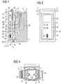
- FIG. 1 shows a side view of a module 1, which is held on a rear wall unit 2 and rests with its rear side 3 at this.
- FIG. 2 shows a back view and
- FIG. 3 a front view of the module 1, which is held together with other modules 4 in a row next to each other on the rear wall unit 2.
- the top 5 of the module 1 is in FIG. 4 shown.
- the module 1 contains a microfluidic unit 6, here in the form of a planar microfluidic part, which is arranged and held parallel to this in the region of the top side 5 of the module 1.
- the microfluidic part 6 contains in its interior fluid channels 7, depending on the function of the module 1, for example form a reactor, a mixer or a residence section for fluids or a plurality of such functional units and extend substantially parallel to the two large-scale main times of the planar microfluidic part 6.
- As the module 4, are provided, open into fluid ports 8, which are included on the upwardly facing main side of the microfluidic part 6 in close to the adjacent modules areas.
- microfluidic or macrofluidic units here z. B. a pump 10.
- microfluidic or macrofluidic units 10 are housed within the module 1 in a space below the microfluidic part 6.
- connection parts 11 are fluidly connected to one another via connection parts 11 with connection channels 12 contained therein.
- the connecting parts 11 can be mounted from the outside against the microfluidic parts 6, in each case bridging the microfluidic parts 6 of the immediately adjacent modules 1 and 4 and connecting the fluid connections 8 of the respectively adjacent microfluidic parts 6 to one another via their connecting channels 12.
- the connecting part 11 mounted on the side with the missing neighboring module serves to connect external fluid lines 13 for supply and disposal of the module row with or from fluids.
- the modules 1, 4 actuatable locking parts 14, with which the connecting parts 11 are pressed against the microfluidic parts 6.
- the module 1 includes an electrical control unit 15, the functions such. B. valve positions or analysis operations, in the microfluidic unit 6 and / or the additional fluidic units 10 controls, and measured values, such as As temperature, pressure, flow or analysis results, detected by the units 6 and / or 10.
- the control unit 15 is arranged in the module 1 at the rear side 3 and thus thermally decoupled from the microfluidic unit 6.
- the control unit 15 is mounted on a heat conducting body 16, which is arranged in the region of the back 13 of the module 1 within a recess 17, wherein the control unit 15 may come to rest within the recess 17.
- the recess 17 is surrounded by a seal 18 and forms with the rear wall unit 2, on which the module 1 is held, a closed sealed cavity 19th
- the rear wall unit 2 includes an electrical line bus 20 with data and power supply lines, a forced cooling 21, here in the form of a coolant circuit, and a plurality of fluid lines 22, 23, 24 for guiding auxiliary fluids, such.
- the forced cooling 21 is arranged such that it directly opposite the electrical control unit 15 in the module 1, so that the waste heat of the electrical control unit 15th is introduced via the heat-conducting body 16 and optionally a heat-conducting rubber 25 directly into the rear wall unit 2 with the forced cooling 21 present there.
- the electrical connection between the control unit 15 and the electrical line bus 20 is effected by electrical connector parts 26 and 27 arranged on the rear wall unit 2 and the rear side 3 of the module 1.
- the fluidic connection between the fluidic units 6 and 10 and the fluid lines 23 and 24 takes place by fluidic connector parts 28, 29 and 30, 31.
- the fluid line 22 is supplied via a branch 32, the cavity 19 with a purge gas, so that in the cavity 19 can penetrate from the outside no flammable gas mixtures.
- the electrical line bus 20, the fluid lines 22, 23, 24 and the coolant circuit 21 have additional connection terminals 33 to 38 on the vertical narrow side of the rear wall unit 2.
- the rear wall unit 2 has in its upper region a mounting rail 39 to which the module 1 is suspended by means of a hooking device 40.
- a screw 41 is provided in the lower region.
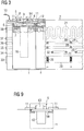
- FIG. 5 embodiment shown differs from the previous one in that not the microfluidic part 6, but the connecting parts 11 are held directly on the module 1, wherein the connecting parts 11 with their outwardly, ie upwardly facing, facing main sides form a reference plane for the microfluidic parts 6, which are pressed from the outside against the connecting parts 11.
- Both the fluid connections 8 and 9 serving for connection to the adjacent microfluidic parts and for connection to the additional fluidic units 10 lie on a single, namely the downwardly facing main side of the microfluidic part 6.
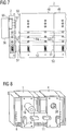
- FIG. 6 shows an example of the mounting of the connecting parts in a mountable directly to the module 1 receiving part 44, wherein on the microfluidic parts 6 facing top a template portion 45 with the fluid ports 8 in the microfluidic 6 opposite openings 46 for receiving sealing rings 47 rests.
- FIG. 7 shows another embodiment for the rear wall unit 2, which is composed of rear wall segments 48, 49.
- the rear wall segments 48, 49 have connecting connections 51, 52 for the line bus segments 53 and fluid line segments 54 contained in the rear wall segments 48, 49 at the joints 50.
- the rear wall unit 2 on its side facing away from the modules mounting locations 55 for attaching additional equipment 56, such.
- As pressure generator for auxiliary fluids which are connectable to the lines in the rear wall unit 2 or, as shown here, via terminals 57 in the rear wall unit 2 with the modules held thereon.
- FIG. 8 shows an embodiment with two modules 1 and 4, in which the microfluidic parts 6 and the connection parts 11 connecting them are arranged on the front side of the modules 1 and 4.
- the connecting parts 11 pressed by means of locking parts 14 from the outside against the microfluidic parts 6.
- Further fluidic accessories 10 can be mounted on the outside of the modules 1 and 4, wherein they are fluidly connected via fluid passages in a sealing member 58 with the microfluidic part 6.
- FIG. 9 a schematic representation of an embodiment in which the microfluidic 6 is held directly in the module 1 and the connecting parts 11 are mounted from the outside against the microfluidic 11.
- the microfluidic unit 6 consists of a fluid distributor plate 59, on the upper side of which the connecting parts 11 rest under pressure and on which several microfluidic subunits 60 are applied next to one another. On the underside of the fluid distribution plate 59 further fluidic accessories 10 can be mounted.
Landscapes
- Chemical & Material Sciences (AREA)
- Organic Chemistry (AREA)
- Chemical Kinetics & Catalysis (AREA)
- Physical Or Chemical Processes And Apparatus (AREA)
- Cooling Or The Like Of Electrical Apparatus (AREA)
- Micromachines (AREA)
Description
- Die Erfindung betrifft ein Mikrofluidiksystem, wie es gleichermaßen aus der
WO 01/36085 A1 WO 01/73823 A2 WO 02/065221 A2 WO 02/065221 A2 - Die
DE 199 17 398 A1 offenbart ein Mikrofluidiksystem, bei dem eine Reihe von nebeneinander stehenden Modulen auf einer Kopplungsschiene montiert ist, die sowohl einen elektrischen Leitungsbus zur elektrischen Verbindung von moduleigenen Steuereinheiten als auch Verbindungskanäle zur fluidischen Verbindung von moduleigenen Mikrofluidikeinheiten enthält. - Aus Quiram D.J. et al.: "Package Level Integration of Silicon Microfabricated Reactors to Form a Miniature Reactor Test System", Technical Digest, IEEE Solid State Sensor and Actuator Workshop, New York, 2000, Seiten 166-169 ist ein modulares Mikrofluidiksystem bekannt, bei dem elektronische Baugruppen in einem Baugruppenträger eingeschoben und darin über einen Rückwandbus miteinander elektrisch verbunden sind. Auf den einzelnen Baugruppen sind Mikrofluidikeinheiten, hier Reaktoren, in Fassungen mit elektrischen und fluidischen Anschlüssen gehalten. Die Mikrofluidikeinheiten werden durch elektrische Steuereinheiten auf den Baugruppen gesteuert. Die Baugruppen weisen auf ihren Vorderseiten Fluidanschlüsse auf, über die sie nach außen und untereinander fluidisch verbindbar sind.
- Je nach Anforderung müssen die Mikrofluidikeinheiten gekühlt oder beheizt werden, um beispielsweise im Falle einer chemischen Reaktion von Fluiden in einem Mikroreaktor die Reaktionstemperatur einzustellen bzw. die bei der Reaktion frei werdende Wärme abzuführen. Die elektrischen Steuereinheiten sind einerseits wärmeempfindlich und erzeugen andererseits selbst Abwärme.
- Das erfindungsgemäße Mikrofluidiksystem besteht nun aus in einer Reihe nebeneinander angeordneten Modulen, die jeweils eine Mikrofluidikeinheit und eine zugehörige, modulspezifische Funktionen in der Mikrofluidikeinheit steuernde und Messwerte erfassende elektrische Steuereinheit enthalten,
- wobei die Module mit ihren Rückseiten an einer gemeinsamen senkrechten Rückwandeinheit anliegen und an dieser gehalten sind,
- wobei in den Modulen die jeweilige Steuereinheit im Bereich der Rückseite und die Mikrofluidikeinheit in einem von der Rückseite entfernten Bereich angeordnet ist,
- wobei die Steuereinheiten über an den Rückseiten der Module und an der Rückwandeinheit angeordnete elektrische Steckverbinderteile mit einem in der Rückwandeinheit verlaufenden elektrischen Leitungsbus verbunden sind und
- wobei die Mikrofluidikeinheiten in den unterschiedlichen Modulen mit jeweils einer Fluidanschlüsse enthaltenden Seite nebeneinander in einer gemeinsamen Ebene liegen und Verbindungskanäle enthaltende Verbindungsteile in dieser Ebene an den Mikrofluidikteilen anliegen, wobei jeweils zwei benachbarte Mikrofluidikteile von jeweils einem Verbindungsteil teilweise überlappt werden und das Verbindungsteil die in dem Überlappungsbereich liegenden Fluidanschlüsse der benachbarten Mikrofluidikteile über seine Verbindungskanäle miteinander verbindet.
- Da die elektrischen Steuereinheiten im rückseitigen Bereich der Module angeordnet sind, kann die von den Steuereinheiten erzeugte Abwärme effektiv über die zur Halterung der Module dienende Rückwandeinheit abgeführt werden. Die Nähe der Steuereinheiten zu der Rückwandeinheit wird dabei genutzt, den die Steuereinheiten verbindenden elektrischen Leitungsbus, also die Daten- und Energieversorgungsleitungen, in die Rückwandeinheit zu verlegen, wobei die Verbindung zwischen den Steuereinheiten und dem Leitungsbus über Steckverbinderteile erfolgt. Da der Leitungsbus nicht abschnittsweise in den Modulen verläuft, sondern von diesen getrennt ist, ist die Anzahl der benötigten und insbesondere der in Reihe liegenden elektrischen Steckverbinder minimiert. Die Mikrofluidikeinheiten sind wärmemäßig von den elektrischen Steuereinheiten entkoppelt, indem sie in einem von der Rückseite entfernten Bereich, beispielsweise der Vorder- oder Oberseite der Module, angeordnet sind und dort mittels der die jeweils benachbarten Module überbrückenden Verbindungsteile fluidisch verbindbar sind. Bei Anordnung im Bereich der Vorder- oder Oberseite der Module sind die Mikrofluidikeinheiten außerdem leicht zugänglich und können, beispielsweise im Fehler- oder Verschleißfall, leicht ausgetauscht werden. Das Mikrofluidiksystem kann zusätzliche Module ohne Fluideinheiten, wie z. B. Energie- oder Druckversorgungsmodule, oder Module ohne Steuereinheiten, wie z. B. Fluidver- oder entsorgungsbehälter, enthalten, die in gleicher Weise, wie die übrigen Module, an der Rückwandeinheit gehalten sind.
- Zur Reduzierung des schaltungstechnischen Aufwandes sind die Steuereinheiten in den Modulen nur zur Ausübung modulspezifischer Funktionen ausgebildet, wobei darüber hinaus gehende, modulübergreifende Funktionen durch eine zusätzliche Steuereinheit ausgeübt werden, die in der Rückwandeinheit integriert oder an dieser, beispielsweise in Form eines zusätzlichen Moduls, gehalten ist.
- Vorzugsweise sind die Mikrofluidikeinheiten im Bereich der Oberseite der jeweiligen Module angeordnet, so dass weitere mikrofluidische oder makrofluidische Einheiten, wie z. B. Pumpen, Ventile usw., unterhalb der betreffenden Mikrofluidikeinheit in dem Modul angeordnet und mit der Mikrofluidikeinheit fluidisch verbunden werden können. Es ist aber auch möglich, bei Anordnung der Mikrofluidikeinheiten an der Vorder- oder Oberseite der Module die weiteren mikro- oder makrofluidischen Einheiten von außen an den Modulen zu montieren und dabei mit den Mikrofluidikeinheiten zu verbinden.
- Die Mikrofluidikeinheiten in den unterschiedlichen Modulen liegen mit jeweils einer Fluidanschlüsse enthaltenden Seite nebeneinander in einer gemeinsamen Ebene, wobei die Verbindungsteile in dieser Ebene derart an den Mikrofluidikteilen anliegen, dass jeweils zwei benachbarte Mikrofluidikteile von jeweils einem Verbindungsteil teilweise überlappt werden und dass das Verbindungsteil die in dem Überlappungsbereich liegenden Fluidanschlüsse der benachbarten Mikrofluidikteile über seine Verbindungskanäle miteinander verbindet. Die Fluidverbindung erfolgt somit unmittelbar über die Fluidanschlüsse in den Mikrofluidikteilen und die Verbindungskanäle in den daran anliegenden Verbindungsteilen, wobei im Bereich der Fluidanschlüsse gegebenenfalls lediglich Dichtungsmittel, wie z. B. Dichtringe, erforderlich sind, um das System nach außen hin abzudichten. Schlauchleitungen zwischen den Mikrofluidikteilen werden auf diese Weise vermieden, so dass die Fluide nur in den Kanälen der Mikrofluidikteile und der Verbindungsteile geführt werden. Außerhalb der Überlappungsbereiche können die Mikrofluidikeinheiten weitere Fluidanschlüsse zum Anschluss beispielsweise der bereits erwähnten weiteren mikrofluidischen oder makrofluidischen Einheiten aufweisen.
- Die Mikrofluidikeinheiten sind als planare Mikrofluidikteile, beispielsweise als Einzelplatte oder in Form eines Plattenverbunds aus Stahl, Glas, Silizium oder einem anderen geeigneten Material, ausgebildet. Innerhalb der Platte bzw. den Platten verlaufen Fluidkanäle im Wesentlichen parallel zu den beiden großflächigen Plattenhauptseiten und sind dazu senkrecht mit den Fluidanschlüssen und gegebenenfalls weiteren Fluidanschlüssen in einer der beiden oder beiden außen liegenden Plattenhauptseiten verbunden. Der Plattenverbund kann auch in der Weise aufgebaut sein, dass auf einer Fluidverteilerplatte, welche auch die Fluidanschlüsse zur Verbindung mit den benachbarten Mikrofluidikeinheiten enthält, die eigentliche Mikrofluidikeinheit oder auch mehrere Mikrofluidik-Untereinheiten neben- oder übereinander aufgebracht sind. Die Verbindungsteile sind vorzugsweise ebenfalls als Platten und aus demselben Material wie die planaren Mikrofluidikteile ausgebildet, so dass die Bildung von elektrischen Lokalelementen verhindert wird.
- Die Verbindungsteile können unmittelbar an den nebeneinander liegenden Modulen gehalten werden, wobei sie mit ihren die Fluidanschlüsse enthaltenden Seiten nach außen gewandt in einer gemeinsamen Ebene zu liegen kommen. Die Mikrofluidikeinheiten werden dann von außen gegen die Verbindungsteile montiert, so dass sie an diesen unter Druck anliegen. Dies ist insbesondere dann von Vorteil, wenn die Mikrofluidikeinheiten zerbrechlich sind und nur eine gleichmäßig verteilte Druckbelastung vertragen oder wenn die Mikrofluidikeinheiten in den unterschiedlichen Modulen unterschiedliche Bauhöhen aufweisen; die Verbindungsteile definieren dann mit ihren nach außen gewandten Seiten eine Referenzebene für die aufliegenden Mikrofluidikeinheiten.
- Ist die Druckbeaufschlagung der Mikrofluidikeinheiten, wie z. B. bei planaren Teilen aus Stahl oder exakt planaren Glasteilen mit geringen Fertigungstoleranzen, unkritisch, so können die Mikrofluidikeinheiten unmittelbar an den Modulen gehalten werden, wobei dann die Verbindungsteile von außen gegen die Mikrofluidikeinheiten montierbar sind. Dies hat den Vorteil, dass die Mikrofluidikeinheiten in den Modulen eingebaut werden können bevor diese an der Rückwandeinheit befestigt und die Verbindungsteile zwischen jeweils benachbarten Modulen montiert werden. Wenn ein Modul in dem System ausgewechselt werden soll, muss daher auch nicht zuerst die Mikrofluidikeinheit aus dem betreffenden Modul entfernt werden.
- Die weisen Module bevorzugt betätigbare Verriegelungsteile, beispielsweise Deckelteile, auf, die im Verriegelungszustand bzw. in geschlossenem Zustand die von außen montierbaren Mikrofluidikeinheiten bzw. Verbindungsteile gegen die unmittelbar an den Modulen gehaltenen Mikrofluidikeinheiten bzw. Verbindungsteile pressen. Der Anpressdruck kann dabei unmittelbar oder bevorzugt über elastische Andruckelemente, wie Federbeine, pneumatisch betätigbare Stempel, oder über flüssigkeits- oder gasgefüllte Kissen ausgeübt werden, was insbesondere auch dann von Vorteil ist, wenn die anzudrückenden Teile aus herstellungstechnischen Gründen nicht exakt planar ausgerichtet werden können, so dass eine gleichmäßige Druckbeaufschlagung mittels Schraubverbindungen oder anderer Andruckelemente nicht realisierbar ist.
- Neben dem elektrischen Leitungsbus enthält die Rückwandeinheit, an der die Module montiert sind, vorzugsweise mindestens eine Fluidleitung, die mindestens ein Hilfsfluid führt, wie z. B. ein Kühl- oder Heizfluid zum Temperieren der Mikrofluidikeinheiten in den Modulen, Druckluft zum Betätigen von pneumatischen Stellgliedern in den Modulen, ein Reinigungsfluid zum Spülen der Fluidkanäle in den Mikrofluidikeinheiten oder ein Spülgas zum Austreiben entzündlicher Gasgemische aus den Modulen. Die Module sind dabei an ihren Rückseiten über entsprechende fluidische Steckverbinderteile mit der mindestens einen Fluidleitung in der Rückwandeinheit verbindbar.
- Zur besseren Abfuhr der von den elektrischen Steuereinheiten in den Modulen erzeugten Wärme kann die Rückwandeinheit in vorteilhafter Weise in ihrem den Steuereinheiten in den Modulen gegenüberliegenden Bereich Mittel zur Zwangskühlung aufweisen, wie z. B. eine von einem Kühlmittel durchflossene Kühlschlange, einen Lüfter oder Peltier-Elemente.
- Der Wärmeübergang von den elektrischen Steuereinheiten in den Modulen auf die Rückwandeinheit lässt sich dadurch verbessern, dass die Steuereinheiten in den Modulen jeweils auf einem Wärmeleitkörper montiert werden, der mit einer Wärmeübertragungsfläche, gegebenenfalls unter Zwischenlage eines Wärmeleitgummis oder ähnlichem, flächig an der Rückwandeinheit anliegt.
- Ein Einsatz des erfindungsgemäßen Mikrofluidiksystems in explosionsgefährdeten Bereichen wird in vorteilhafter Weise dadurch ermöglicht, dass die Rückseiten der Module jeweils mindestens eine Ausnehmung enthalten, die zusammen mit der Rückwandeinheit einen nach außen abgedichteten Hohlraum bildet, in dem die elektrischen Steckverbinderteile zu liegen kommen. Dabei können zusätzlich auch die elektrische Steuereinheit und gegebenenfalls die fluidischen Steckverbinderteile innerhalb des jeweiligen Hohlraums angeordnet sein. Im Weiteren kann in der Rückwandeinheit eine Fluidleitung für ein Spülfluid vorgesehen werden, wobei von der Fluidleitung Abzweige in die Hohlräume führen, so dass diese von dem Spülfluid durchströmt werden. Das Spülfluid verhindert das Eindringen von Luft (Sauerstoff) von außen in die Hohlräume bzw. verdünnt und entfernt in den Hohlräumen vorhandene entzündliche Gasgemische. Außerdem bewirkt das Spülfluid eine unmittelbare Kühlung der Steckverbinder und der elektrischen Steuereinheiten.
- Die einzelnen Module können auf unterschiedliche Weise an der Rückwandeinheit gehalten werden. Vorzugsweise werden sie an der Rückwandeinheit angehängt, wozu die Module im oberen Bereich ihrer Rückseiten Mittel zum Einhängen in eine Einhängvorrichtung, z. B. Montageschiene, im oberen Bereich der Rückwandeinheit aufweisen. Auf diese Weise lassen sich auch schwere Module einfach und sicher an der Rückwandeinheit befestigen. Zur Fixierung der Module weisen diese im unteren Bereich ihrer Rückseiten vorzugsweise Mittel, wie z. B. Schraub- oder Schnappverbindungen oder sonstige Verriegelungseinrichtungen, auf, um die Module mit ihren Rückseiten gegen die Rückwandeinheit zu pressen und so die Wärmeableitung von den Steuereinheiten in den Modulen auf die Rückwandeinheit bzw. die Abdichtung der die elektrischen Steckverbinderteile aufnehmenden Hohlräume zu verbessern.
- Um die Modularität des erfindungsgemäßen Mikrofluidiksystems zu erhöhen und beispielsweise auch Subsysteme bilden und miteinander verbinden zu können, ist die Rückwandeinheit in vorteilhafter Weise aus Rückwandsegmenten zusammenfügbar, die an den Fügestellen Verbindungsanschlüsse für die in den Rückwandsegmenten enthaltenen Leitungsbussegmente und gegebenenfalls Fluidleitungssegmente aufweisen. Die Rückwandsegmente weisen jeweils eine vorgegebene Anzahl von Montageplätzen für die Module auf und erlauben es, Rückwandeinheiten beliebiger Länge zu bilden.
- Wie bereits erwähnt, können Zusatzeinrichtungen, insbesondere makrofluidische Einheiten, wie z. B. Pumpen, Ventile usw., innerhalb der Module angeordnet werden. Soweit diese in den einzelnen Modulen keinen Platz mehr finden oder nicht modulspezifische, sondern übergeordnete Funktionen wahrnehmen, wie z. B. bei übergeordneten Einheiten für die Prozessüberwachung oder beispielsweise Druckerzeuger für Hilfsfluide (z. B. Druckluft), kann vorgesehen werden, dass die Rückwandeinheit auf ihrer von den Modulen abgewandten Seite Montageplätze mit Anschlüssen zur Montage und zum Anschließen dieser Zusatzeinrichtungen aufweist.
- Zur weiteren Erläuterung der Erfindung wird im Folgenden auf die Figuren der Zeichnung Bezug genommen; im Einzelnen zeigen:
- Figur 1
- ein erstes Ausführungsbeispiel für ein an einer Rückwandeinheit gehaltenes Modul in Seitenansicht,
- Figur 2
- eine Rückansicht des Moduls,
- Figur 3
- eine Vorderansicht des Moduls an der Rückwandeinheit zusammen mit einem weiteren benachbarten Modul,
- Figur 4
- die Oberseite des Moduls,
- Figur 5
- ein weiteres Ausführungsbeispiel für das Modul,
- Figur 6
- ein Beispiel für die Montage der Verbindungsteile bei dem Ausführungsbeispiel nach
Figur 5 , - Figur 7
- ein alternatives Ausführungsbeispiel für die Rückwandeinheit,
- Figur 8
- ein Beispiel für die Montage der Mikrofluidikeinheiten und Verbindungsteile an der Vorderseite der Module und
- Figur 9
- noch ein Beispiel für das Modul.
-
Figur 1 zeigt in Seitenansicht ein Modul 1, das an einer Rückwandeinheit 2 gehalten ist und mit seiner Rückseite 3 an dieser anliegt.Figur 2 zeigt eine Rückansicht undFigur 3 eine Vorderansicht des Moduls 1, welches zusammen mit weiteren Modulen 4 in einer Reihe nebeneinander an der Rückwandeinheit 2 gehalten ist. Die Oberseite 5 des Moduls 1 ist inFigur 4 dargestellt. - Das Modul 1 enthält eine Mikrofluidikeinheit 6, hier in Form eines planaren Mikrofluidikteils, das im Bereich der Oberseite 5 des Moduls 1 parallel zu dieser angeordnet und gehalten ist. Das Mikrofluidikteil 6 enthält in seinem Inneren Fluidkanäle 7, die je nach Funktion des Moduls 1 beispielsweise einen Reaktor, einen Mischer oder eine Verweilstrecke für Fluide oder mehrere solche Funktionseinheiten bilden und im Wesentlichen parallel zu den beiden großflächigen Hauptzeiten des planaren Mikrofluidikteils 6 verlaufen. Diejenigen Fluidkanäle 7, die zur Verbindung mit Fluidkanälen in den Mikrofluidikteilen benachbarter Module, hier z. B. das Modul 4, vorgesehen sind, münden in Fluidanschlüssen 8, die auf der nach oben gewandten Hauptseite des Mikrofluidikteils 6 in zu den benachbarten Modulen nahen Bereichen enthalten sind. Weitere Fluidanschlüsse 9 auf der nach unten gewandten Hauptseite des Mikrofluidikteils 6 dienen zum Anschluss weiterer mikrofluidischer oder makrofluidischer Einheiten, hier z. B. einer Pumpe 10. Diese weiteren mikro- oder makrofluidischen Einheiten 10 sind innerhalb des Moduls 1 in einem Raum unter dem Mikrofluidikteil 6 untergebracht.
- Die Mikrofluidikteile 6 der jeweils benachbarten Module 1 und 4 sind über Verbindungsteile 11 mit darin enthaltenen Verbindungskanälen 12 miteinander fluidisch verbunden. Die Verbindungsteile 11 sind dazu von außen gegen die Mikrofluidikteile 6 montierbar, wobei sie jeweils die Mikrofluidikteile 6 der unmittelbar benachbarten Module 1 und 4 überbrücken und über ihre Verbindungskanäle 12 die Fluidanschlüsse 8 der jeweils benachbarten Mikrofluidikteile 6 miteinander verbinden. Bei Modulen 1, die als Endmodule in der Reihe nur ein Nachbarmodul 4 haben, dient das auf der Seite mit dem fehlenden Nachbarmodul montierte Verbindungsteil 11 zum Anschluss externer Fluidleitungen 13 zur Ver- und Entsorgung der Modulreihe mit bzw. von Fluiden. Auf ihrer Oberseite 5 weisen die Module 1, 4 betätigbare Verriegelungsteile 14 auf, mit denen die Verbindungsteile 11 gegen die Mikrofluidikteile 6 gepresst werden.
- Wie
Figur 1 zeigt, enthält das Modul 1 eine elektrische Steuereinheit 15, die Funktionen, wie z. B. Ventilstellungen oder Analysenvorgänge, in der Mikrofluidikeinheit 6 und/oder den zusätzlichen fluidischen Einheiten 10 steuert, und Messwerte, wie z. B. Temperatur, Druck, Durchfluss oder Analysenergebnisse, von den Einheiten 6 und/oder 10 erfasst. Die Steuereinheit 15 ist in dem Modul 1 an dessen Rückseite 3 angeordnet und so von der Mikrofluidikeinheit 6 thermisch entkoppelt. Bei dem gezeigten Ausführungsbeispiel ist die Steuereinheit 15 auf einem Wärmeleitkörper 16 montiert, der im Bereich der Rückseite 13 des Moduls 1 innerhalb einer Ausnehmung 17 angeordnet ist, wobei die Steuereinheit 15 auch innerhalb der Ausnehmung 17 zu liegen kommen kann. Die Ausnehmung 17 ist von einer Dichtung 18 umgeben und bildet mit der Rückwandeinheit 2, an der das Modul 1 gehalten ist, einen geschlossenen abgedichteten Hohlraum 19. - Die Rückwandeinheit 2 enthält einen elektrischen Leitungsbus 20 mit Daten- und Energieversorgungsleitungen, eine Zwangskühlung 21, hier in Form eines Kühlmittelkreislaufs, sowie mehrere Fluidleitungen 22, 23, 24 zur Führung von Hilfsfluiden, wie z. B. Kühlflüssigkeiten für die Mikrofluidikeinheiten 6, Druckluft zur Steuerung pneumatischer Einheiten 10 oder Spülgas zum Spülen des Hohlraums 19. Die Zwangskühlung 21 ist derart angeordnet, dass sie der elektrischen Steuereinheit 15 in dem Modul 1 direkt gegenüberliegt, so dass die Abwärme der elektrischen Steuereinheit 15 über den Wärmeleitkörper 16 und gegebenenfalls ein Wärmeleitgummi 25 unmittelbar in die Rückwandeinheit 2 mit der dort vorhandenen Zwangskühlung 21 eingeleitet wird. Die elektrische Verbindung zwischen der Steuereinheit 15 und dem elektrischen Leitungsbus 20 erfolgt durch an der Rückwandeinheit 2 und der Rückseite 3 des Moduls 1 angeordnete elektrische Steckverbinderteile 26 und 27. Ebenso erfolgt die fluidische Verbindung zwischen den fluidischen Einheiten 6 und 10 und den Fluidleitungen 23 und 24 durch fluidische Steckverbinderteile 28, 29 bzw. 30, 31. Die Fluidleitung 22 versorgt über einen Abzweig 32 den Hohlraum 19 mit einem Spülgas, so dass in den Hohlraum 19 von außen keine entzündlichen Gasgemische eindringen können. Der elektrische Leitungsbus 20, die Fluidleitungen 22, 23, 24 und der Kühlmittelkreislauf 21 weisen zusätzliche Verbindungsanschlüsse 33 bis 38 an der senkrechten Schmalseite der Rückwandeinheit 2 auf.
- Die Rückwandeinheit 2 weist in ihrem oberen Bereich eine Montageschiene 39 auf, an der das Modul 1 mittels einer Einhängvorrichtung 40 eingehängt ist. Zur Fixierung des Moduls 1 und zum Anpressen seiner Rückseite 3 mit dem Wärmeleitkörper 16 und der dem Hohlraum 19 umgebenden Dichtung 18 gegen die Rückwandeinheit 2 ist im unteren Bereich eine Schraubverbindung 41 vorgesehen.
- Das in
Figur 5 gezeigte Ausführungsbeispiel unterscheidet sich von dem vorangegangenen dadurch, dass nicht das Mikrofluidikteil 6, sondern die Verbindungsteile 11 unmittelbar an dem Modul 1 gehalten sind, wobei die Verbindungsteile 11 mit ihren nach außen, d. h. nach oben, gewandten Hauptseiten eine Referenzebene für die Mikrofluidikteile 6 bilden, welche von außen gegen die Verbindungsteile 11 gepresst werden. Sowohl die für die Verbindung mit den benachbarten Mikrofluidikteilen als auch die zur Verbindung mit den zusätzlichen fluidischen Einheiten 10 dienenden Fluidanschlüsse 8 bzw. 9 liegen auf einer einzigen, nämlich der nach unten gewandten Hauptseite des Mikrofluidikteils 6. Auf der davon abgewandten oberen Hauptseite wird das Mikrofluidikteil 6 an den den Fluidanschlüssen 8 bzw. 9 gegenüberliegenden Stellen über Andruckelemente 42, hier Federbeine, die in einem aufklappund schließbaren Deckelteil 43 des Moduls 1 angeordnet sind, elastisch gegen die Verbindungsteile 11 gepresst. -
Figur 6 zeigt ein Beispiel für die Halterung der Verbindungsteile in einem direkt an dem Modul 1 montierbaren Aufnahmeteil 44, wobei auf der den Mikrofluidikteilen 6 zugewandten Oberseite ein Schablonenteil 45 mit den Fluidanschlüssen 8 in dem Mikrofluidikteil 6 gegenüberliegenden Öffnungen 46 zur Aufnahme von Dichtungsringen 47 aufliegt. -
Figur 7 zeigt ein anderes Ausführungsbeispiel für die Rückwandeinheit 2, die aus Rückwandsegmenten 48, 49 zusammengefügt ist. Die Rückwandsegmente 48, 49 weisen an den Fügestellen 50 Verbindungsanschlüsse 51, 52 für die in den Rückwandsegmenten 48, 49 enthaltenen Leitungsbussegmente 53 und Fluidleitungssegmente 54 auf. Zusätzlich weist die Rückwandeinheit 2 auf ihrer von den Modulen abgewandten Seite Montageplätze 55 zum Anbringen von Zusatzeinrichtungen 56, wie z. B. Druckerzeuger für Hilfsfluide, auf, die mit den Leitungen in der Rückwandeinheit 2 oder, wie hier gezeigt, über Anschlüsse 57 in der Rückwandeinheit 2 mit den daran gehaltenen Modulen verbindbar sind. -
Figur 8 zeigt ein Ausführungsbeispiel mit zwei Modulen 1 und 4, bei denen die Mikrofluidikteile 6 und die sie verbindenden Verbindungsteile 11 an der Vorderseite der Module 1 und 4 angeordnet sind. Dabei werden in gleicher Weise wie bei dem Ausführungsbeispiel nachFigur 4 die Verbindungsteile 11 mit Hilfe von Verriegelungsteilen 14 von außen gegen die Mikrofluidikteile 6 gepresst. Weitere fluidische Zusatzeinrichtungen 10 können außen an den Modulen 1 und 4 montiert werden, wobei sie über Fluiddurchführungen in einem Dichtungsteil 58 mit dem Mikrofluidikteil 6 fluidisch verbunden werden. - Schließlich zeigt
Figur 9 in schematischer Darstellung ein Ausführungsbeispiel, bei dem die Mikrofluidikeinheit 6 unmittelbar in dem Modul 1 gehalten ist und die Verbindungsteile 11 von außen gegen die Mikrofluidikeinheit 11 montierbar sind. Die Mikrofluidikeinheit 6 besteht aus einer Fluidverteilerplatte 59, an deren Oberseite die Verbindungsteile 11 unter Druck anliegen und auf der mehrere Mikrofluidik-Untereinheiten 60 nebeneinander aufgebracht sind. An der Unterseite der Fluidverteilerplatte 59 sind weitere fluidische Zusatzeinrichtungen 10 montierbar.
Claims (17)
- Mikrofluidiksystem, bestehend aus in einer Reihe nebeneinander angeordneten Modulen (1, 4), die jeweils eine Mikrofluidikeinheit (6) und eine zugehörige, modulspezifische Funktionen in der Mikrofluidikeinheit (6) steuernde und Messwerte erfassende elektrische Steuereinheit (15) enthalten,- wobei die Module (1, 4) mit ihren Rückseiten (3) an einer gemeinsamen senkrechten Rückwandeinheit (2) anliegen und an dieser gehalten sind,- wobei die Mikrofluidikeinheiten als planare Mikrofluidikteile ausgebildet sind,- wobei in den Modulen (1, 4) die jeweilige Steuereinheit (15) im Bereich der Rückseite (3) und die Mikrofluidikeinheit (6) in einem von der Rückseite (3) entfernten Bereich angeordnet ist,- wobei die Steuereinheiten (15) über an den Rückseiten (3) der Module (1, 4) und an der Rückwandeinheit (2) angeordnete elektrische Steckverbinderteile (26, 27) mit einem in der Rückwandeinheit (2) verlaufenden elektrischen Leitungsbus (20) verbunden sind und- wobei die Mikrofluidikeinheiten (6) in den unterschiedlichen Modulen (1, 4) mit jeweils einer Fluidanschlüsse (8) enthaltenden Seite nebeneinander in einer gemeinsamen Ebene liegen und Verbindungskanäle (12) enthaltende Verbindungsteile (11) in dieser Ebene an den Mikrofluidikteilen (6) anliegen, wobei jeweils zwei benachbarte Mikrofluidikteile (6) von jeweils einem Verbindungsteil (11) teilweise überlappt werden und das Verbindungsteil (11) die in dem Überlappungsbereich liegenden Fluidanschlüsse (8) der benachbarten Mikrofluidikteile (6) über seine Verbindungskanäle (12) miteinander verbindet.
- Mikrofluidiksystem nach Anspruch 1, dadurch gekennzeichnet, dass die Steuereinheiten (15) in den Modulen (1, 4) nur zur Ausübung modulspezifischer Funktionen ausgebildet sind und dass darüber hinaus gehende, modulübergreifende Funktionen durch eine zusätzliche Steuereinheit ausgeübt werden, die in der Rückwandeinheit integriert oder an dieser gehalten ist.
- Mikrofluidiksystem nach Anspruch 1 oder 2, dadurch gekennzeichnet, dass die Mikrofluidikeinheiten (6) im Bereich der Oberseite (5) der jeweiligen Module (1, 4) angeordnet sind und dass weitere mikrofluidische und/oder makrofluidische Einheiten (10) in den Modulen (1, 4) unterhalb der betreffenden Mikrofluidikeinheit (6) angeordnet und mit dieser fluidisch verbunden sind.
- Mikrofluidiksystem nach einem der vorangehenden Ansprüche, dadurch gekennzeichnet, dass die Verbindungsteile (11) an den Modulen (1, 4) gehalten sind und dass die Mikrofluidikeinheiten (6) von außen gegen die Verbindungsteile montierbar sind.
- Mikrofluidiksystem nach Anspruch 1, 2 oder 3, dadurch gekennzeichnet, dass die Mikrofluidikeinheiten (6) an den Modulen (1, 4) gehalten sind und dass die Verbindungsteile (11) von außen gegen die Mikrofluidikeinheiten (6) montierbar sind.
- Mikrofluidiksystem nach Anspruch 4 oder5, dadurch gekennzeichnet, dass die Module (1, 4) betätigbare Verriegelungsteile (14) aufweisen, die im Verriegelungszustand die von außen montierbaren Mikrofluidikeinheiten (6) bzw. Verbindungsteile (11) gegen die an den Modulen (1, 4) gehaltenen Mikrofluidikeinheiten (6) bzw. Verbindungsteile (11) pressen.
- Mikrofluidiksystem nach Anspruch 6, dadurch gekennzeichnet, dass die Verriegelungsteile als Deckelteile (43) ausgebildet sind, die in geschlossenem Zustand die von außen montierbaren Mikrofluidikeinheiten (6) bzw. Verbindungsteile (11) gegen die an den Modulen (1, 4) gehaltenen Mikrofluidikeinheiten (6) bzw. Verbindungsteile (11) pressen.
- Mikrofluidiksystem nach einem der vorangehenden Ansprüche, dadurch gekennzeichnet, dass die Module (1, 4) über an ihren Rückseiten (3) und an der Rückwandeinheit (2) angeordnete fluidische Steckverbinderteile (28 bis 31) mit mindestens einer in der Rückwandeinheit (2) verlaufenden und mindestens ein Hilfsfluid führenden Fluidleitung (23, 24) verbindbar sind.
- Mikrofluidiksystem nach einem der vorangehenden Ansprüche, dadurch gekennzeichnet, dass die Rückwandeinheit (2) in ihrem den Steuereinheiten (15) in den Modulen (1, 4) gegenüberliegenden Bereich Mittel (21) zur Zwangskühlung aufweist.
- Mikrofluidiksystem nach einem der vorangehenden Ansprüche, dadurch gekennzeichnet, dass in den Modulen (1, 4) die jeweilige elektrische Steuereinheit (15) auf einen Wärmeleitkörper (16) montierbar ist, der mit einer Wärmeübertragungsfläche flächig an der Rückwandeinheit (2) anliegt.
- Mikrofluidiksystem nach einem der vorangehenden Ansprüche, dadurch gekennzeichnet, dass die Rückseiten (3) der Module (1, 4) jeweils mindestens eine Ausnehmung (17) enthalten, die zusammen mit der Rückwandeinheit (2) einen nach außen abgedichteten Hohlraum (19) bildet, in dem die elektrischen Steckverbinderteile (26, 27) zu liegen kommen.
- Mikrofluidiksystem nach Anspruch 11, dadurch gekennzeichnet, dass die elektrische Steuereinheit (15) in dem Hohlraum (19) angeordnet ist.
- Mikrofluidiksystem nach Anspruch 11 oder12, dadurch gekennzeichnet, dass in der Rückwandeinheit (2) eine Fluidleitung (22) für ein Spülfluid verläuft und dass von dieser Fluidleitung (22) Abzweige (32) in die Hohlräume (19) führen.
- Mikrofluidiksystem nach einem der vorangehenden Ansprüche, dadurch gekennzeichnet, dass die Module (1, 4) im oberen Bereich ihrer Rückseiten (3) Mittel (40) zum Einhängen der Module (1, 4) in eine Einhängvorrichtung (39) im oberen Bereich der Rückwandeinheit (2) aufweisen.
- Mikrofluidiksystem nach Anspruch 14, dadurch gekennzeichnet, dass die Module (1, 4) im unteren Bereich ihrer Rückseiten (3) Mittel (41) zum Anpressen der Module (1, 4) mit ihren Rückseiten (3) gegen die Rückwandeinheit (2) aufweisen.
- Mikrofluidiksystem nach einem der vorangehenden Ansprüche, dadurch gekennzeichnet, dass die Rückwandeinheit (2) aus Rückwandsegmenten (48, 49) zusammenfügbar ist, die an den Fügestellen Verbindungsanschlüsse (51, 52) für die in den Rückwandsegmenten (48, 49) enthaltenen Leitungsbussegmente (53) und gegebenenfalls Fluidleitungssegmente (54) aufweisen.
- Mikrofluidiksystem nach einem der vorangehenden Ansprüche, dadurch gekennzeichnet, dass die Rückwandeinheit (2) auf ihrer von den Modulen (1, 4) abgewandten Seite Montageplätze (55) mit Anschlüssen zur Montage und zum Anschließen von Zusatzeinrichtungen (56) aufweist.
Applications Claiming Priority (2)
| Application Number | Priority Date | Filing Date | Title |
|---|---|---|---|
| DE102004022423A DE102004022423A1 (de) | 2004-05-06 | 2004-05-06 | Mikrofluidiksystem |
| PCT/EP2005/004951 WO2005107937A1 (de) | 2004-05-06 | 2005-05-06 | Mikrofluidiksystem |
Publications (2)
| Publication Number | Publication Date |
|---|---|
| EP1742732A1 EP1742732A1 (de) | 2007-01-17 |
| EP1742732B1 true EP1742732B1 (de) | 2012-04-11 |
Family
ID=34967518
Family Applications (1)
| Application Number | Title | Priority Date | Filing Date |
|---|---|---|---|
| EP05739470A Expired - Lifetime EP1742732B1 (de) | 2004-05-06 | 2005-05-06 | Mikrofluidiksystem |
Country Status (7)
| Country | Link |
|---|---|
| US (1) | US20090010820A1 (de) |
| EP (1) | EP1742732B1 (de) |
| JP (1) | JP4660541B2 (de) |
| CN (1) | CN100478063C (de) |
| AT (1) | ATE552905T1 (de) |
| DE (1) | DE102004022423A1 (de) |
| WO (1) | WO2005107937A1 (de) |
Families Citing this family (13)
| Publication number | Priority date | Publication date | Assignee | Title |
|---|---|---|---|---|
| US8021629B2 (en) * | 2005-03-24 | 2011-09-20 | Konica Minolta Medical & Graphic, Inc. | Analyzer |
| DE102005045811A1 (de) * | 2005-09-27 | 2007-04-05 | Siemens Ag | Modulares Mikrofluidiksystem |
| DE102005047041B3 (de) * | 2005-09-30 | 2006-12-14 | Siemens Ag | Mikrofluidiksystem |
| DE102006014845A1 (de) * | 2006-03-30 | 2007-10-04 | Siemens Ag | Modul für ein modulares Mikrofluidiksystem |
| CN101563614A (zh) * | 2006-10-31 | 2009-10-21 | 波凯特有限及两合公司 | 用于液体分析和合成的实验室模块装置及液体分析和合成方法 |
| WO2008135055A1 (de) * | 2007-04-27 | 2008-11-13 | Siemens Aktiengesellschaft | Mikrofluidiksystem |
| JP2012524268A (ja) * | 2009-04-16 | 2012-10-11 | スピンクス インコーポレイテッド | マイクロ流体デバイスをマクロ流体デバイスに接続するための装置及び方法 |
| TW201114481A (en) | 2009-05-11 | 2011-05-01 | Corning Inc | Modular reactor and system |
| US9095850B2 (en) | 2010-03-25 | 2015-08-04 | Endress + Hauser Conducta Gesellschaft für Mess—und Regeltechnik mbH + Co. KG | System for treating liquids |
| DE102010030489A1 (de) * | 2010-03-25 | 2011-09-29 | Endress + Hauser Conducta Gesellschaft für Mess- und Regeltechnik mbH + Co. KG | System zu Behandlung von Flüssigkeiten |
| EP3427830B1 (de) * | 2012-10-24 | 2021-06-23 | Genmark Diagnostics Inc. | Integrierte multiplex-zielanalyse |
| KR20160091362A (ko) | 2013-11-27 | 2016-08-02 | 코닝 인코포레이티드 | 반전도성 중합체의 향상된 유동 반응기 합성 |
| GB201704769D0 (en) | 2017-01-03 | 2017-05-10 | Illumina Inc | Flowcell cartridge with floating seal bracket |
Family Cites Families (25)
| Publication number | Priority date | Publication date | Assignee | Title |
|---|---|---|---|---|
| US3378963A (en) * | 1964-07-30 | 1968-04-23 | Univ Southern Illinois | Science building layout and equipment |
| ES2049254T3 (es) * | 1987-08-27 | 1994-04-16 | Biotrack Inc | Aparato y procedimiento para la dilucion y mezcla de muestras liquidas. |
| US5133937A (en) * | 1989-06-01 | 1992-07-28 | Iniziative Marittime, 1991 S.R.L. | Analysis system having a removable reaction cartridge and temperature control |
| US5225163A (en) * | 1989-08-18 | 1993-07-06 | Angenics, Inc. | Reaction apparatus employing gravitational flow |
| US5273905A (en) * | 1991-02-22 | 1993-12-28 | Amoco Corporation | Processing of slide mounted material |
| US5580523A (en) * | 1994-04-01 | 1996-12-03 | Bard; Allen J. | Integrated chemical synthesizers |
| US5964239A (en) * | 1996-05-23 | 1999-10-12 | Hewlett-Packard Company | Housing assembly for micromachined fluid handling structure |
| DE29807097U1 (de) * | 1998-04-20 | 1998-09-03 | Bürkert Werke GmbH & Co., 74653 Ingelfingen | Modulares elektrofluidisches Baukastensystem |
| US6319476B1 (en) * | 1999-03-02 | 2001-11-20 | Perseptive Biosystems, Inc. | Microfluidic connector |
| DE19917398C2 (de) * | 1999-04-16 | 2002-06-20 | Accoris Gmbh | Modulares chemisches Mikrosystem |
| US6485690B1 (en) * | 1999-05-27 | 2002-11-26 | Orchid Biosciences, Inc. | Multiple fluid sample processor and system |
| DE19928412C2 (de) * | 1999-06-22 | 2002-03-21 | Agilent Technologies Inc | Versorgungselement für einen Labor-Mikrochip |
| WO2001009598A1 (en) * | 1999-07-28 | 2001-02-08 | University Of Washington | Fluidic interconnect, interconnect manifold and microfluidic devices for internal delivery of gases and application of vacuum |
| DE19954855C1 (de) * | 1999-11-15 | 2001-04-05 | Siemens Ag | System zur automatisierten Behandlung von Fluiden, mit einanderreihbaren, austauschbaren Prozeßmodulen |
| JP2001194373A (ja) * | 2000-01-06 | 2001-07-19 | Olympus Optical Co Ltd | 超小型化学操作装置 |
| DE10106558C1 (de) * | 2001-02-13 | 2002-11-07 | Siemens Ag | System zur automatisierten Behandlung von Fluiden, mit aneinanderreihbaren, austauschbaren Prozessmodulen |
| US7010391B2 (en) * | 2001-03-28 | 2006-03-07 | Handylab, Inc. | Methods and systems for control of microfluidic devices |
| JP3990909B2 (ja) * | 2001-12-26 | 2007-10-17 | 旭化成株式会社 | 化学反応用カートリッジ |
| DE10204414A1 (de) * | 2002-02-04 | 2003-09-04 | Siemens Ag | Mikrofluidik-System |
| US6927977B2 (en) * | 2002-02-12 | 2005-08-09 | Siemens Communications, Inc. | Blower exhaust for a closed frame |
| DE10209897A1 (de) * | 2002-03-08 | 2003-09-25 | Merck Patent Gmbh | Mikrokomponenten-Anschlusssystem |
| US20030206832A1 (en) * | 2002-05-02 | 2003-11-06 | Pierre Thiebaud | Stacked microfluidic device |
| US20040101444A1 (en) * | 2002-07-15 | 2004-05-27 | Xeotron Corporation | Apparatus and method for fluid delivery to a hybridization station |
| AU2002318070A1 (en) * | 2002-07-26 | 2004-02-16 | Avantium International B.V. | System for performing a chemical reaction on a plurality of different microreactors |
| DE102005047041B3 (de) * | 2005-09-30 | 2006-12-14 | Siemens Ag | Mikrofluidiksystem |
-
2004
- 2004-05-06 DE DE102004022423A patent/DE102004022423A1/de not_active Withdrawn
-
2005
- 2005-05-06 CN CNB2005800212269A patent/CN100478063C/zh not_active Expired - Fee Related
- 2005-05-06 EP EP05739470A patent/EP1742732B1/de not_active Expired - Lifetime
- 2005-05-06 JP JP2007512043A patent/JP4660541B2/ja not_active Expired - Fee Related
- 2005-05-06 AT AT05739470T patent/ATE552905T1/de active
- 2005-05-06 US US11/579,710 patent/US20090010820A1/en not_active Abandoned
- 2005-05-06 WO PCT/EP2005/004951 patent/WO2005107937A1/de not_active Ceased
Also Published As
| Publication number | Publication date |
|---|---|
| US20090010820A1 (en) | 2009-01-08 |
| CN1972744A (zh) | 2007-05-30 |
| DE102004022423A1 (de) | 2005-12-15 |
| WO2005107937A1 (de) | 2005-11-17 |
| JP2007536542A (ja) | 2007-12-13 |
| ATE552905T1 (de) | 2012-04-15 |
| CN100478063C (zh) | 2009-04-15 |
| EP1742732A1 (de) | 2007-01-17 |
| JP4660541B2 (ja) | 2011-03-30 |
Similar Documents
| Publication | Publication Date | Title |
|---|---|---|
| EP2769426B1 (de) | Vorrichtung zur spannungsversorgung | |
| EP1331665B1 (de) | Kühlvorrichtung | |
| DE112016000129B4 (de) | Wärmetauscher zum Kühlen eines elektrischen Elements, sowie Wärmetauscheranordnung und Kühlmodul | |
| DE3522127C2 (de) | ||
| EP3726612A1 (de) | Batterie und verwendung einer solchen | |
| DE102007001407B4 (de) | Montageanordnung zur Fixierung übereinander angeordneter Leiterplatten in einem Gehäuse | |
| EP3580078B1 (de) | Verfahren zum herstellen eines hochvolt-energiespeichers für ein kraftfahrzeug, sowie hochvolt-energiespeicher für ein kraftfahrzeug | |
| DE102004022423A1 (de) | Mikrofluidiksystem | |
| DE102014101358A1 (de) | Verfahren zum Herstellen eines plattenförmigen Wärmetauschers, plattenförmiger Wärmetauscher und Verbund mit plattenförmigen Wärmetauschern | |
| EP3846188A1 (de) | Elektrische baueinheit in gehäuse aus unterschiedlichen materialien | |
| DE102021210144A1 (de) | Wärmeübertrager | |
| EP4265082A1 (de) | Verfahren zur herstellung einer elektronikbaugruppe, elektronikbaugruppe und kraftfahrzeug | |
| WO2014111194A1 (de) | Kühlvorrichtung, insbesondere für batteriemodule, und fahrzeug, umfassend eine solche kühlvorrichtung | |
| DE102017202303B3 (de) | Elektronikmodul für die industrielle Automatisierung und Verfahren zu seiner Herstellung | |
| EP1928596B1 (de) | Modulares mikrofluidiksystem | |
| EP2693522A1 (de) | Batteriemodul | |
| EP1998885A1 (de) | Modul für ein modulares mikrofluidiksystem | |
| WO2008083878A1 (de) | Fixierungselement für leiterplatten | |
| DE102016120027A1 (de) | Ventilanordnung | |
| EP3956932A1 (de) | Temperierungsvorrichtung | |
| DE102016120029A1 (de) | Ventilanordnung | |
| DE102018209884A1 (de) | Batteriemodul mit einer Mehrzahl an Batteriezellen sowie Verfahren zu dessen Herstellung | |
| DE102022121853A1 (de) | Fluidtemperierbare Traktionsbatterie | |
| DE102021204695A1 (de) | Gehäuse zur Aufnahme von Batteriezellen und elektronischen Komponenten | |
| EP1485645B1 (de) | Anordnung zur behandlung von fluiden |
Legal Events
| Date | Code | Title | Description |
|---|---|---|---|
| PUAI | Public reference made under article 153(3) epc to a published international application that has entered the european phase |
Free format text: ORIGINAL CODE: 0009012 |
|
| 17P | Request for examination filed |
Effective date: 20061107 |
|
| AK | Designated contracting states |
Kind code of ref document: A1 Designated state(s): AT BE BG CH CY CZ DE DK EE ES FI FR GB GR HU IE IS IT LI LT LU MC NL PL PT RO SE SI SK TR |
|
| DAX | Request for extension of the european patent (deleted) | ||
| GRAP | Despatch of communication of intention to grant a patent |
Free format text: ORIGINAL CODE: EPIDOSNIGR1 |
|
| GRAS | Grant fee paid |
Free format text: ORIGINAL CODE: EPIDOSNIGR3 |
|
| GRAA | (expected) grant |
Free format text: ORIGINAL CODE: 0009210 |
|
| AK | Designated contracting states |
Kind code of ref document: B1 Designated state(s): AT BE BG CH CY CZ DE DK EE ES FI FR GB GR HU IE IS IT LI LT LU MC NL PL PT RO SE SI SK TR |
|
| REG | Reference to a national code |
Ref country code: GB Ref legal event code: FG4D Free format text: NOT ENGLISH |
|
| REG | Reference to a national code |
Ref country code: CH Ref legal event code: EP |
|
| REG | Reference to a national code |
Ref country code: AT Ref legal event code: REF Ref document number: 552905 Country of ref document: AT Kind code of ref document: T Effective date: 20120415 |
|
| REG | Reference to a national code |
Ref country code: IE Ref legal event code: FG4D Free format text: LANGUAGE OF EP DOCUMENT: GERMAN |
|
| REG | Reference to a national code |
Ref country code: DE Ref legal event code: R096 Ref document number: 502005012621 Country of ref document: DE Effective date: 20120606 |
|
| REG | Reference to a national code |
Ref country code: NL Ref legal event code: VDEP Effective date: 20120411 |
|
| LTIE | Lt: invalidation of european patent or patent extension |
Effective date: 20120411 |
|
| PG25 | Lapsed in a contracting state [announced via postgrant information from national office to epo] |
Ref country code: PL Free format text: LAPSE BECAUSE OF FAILURE TO SUBMIT A TRANSLATION OF THE DESCRIPTION OR TO PAY THE FEE WITHIN THE PRESCRIBED TIME-LIMIT Effective date: 20120411 Ref country code: FI Free format text: LAPSE BECAUSE OF FAILURE TO SUBMIT A TRANSLATION OF THE DESCRIPTION OR TO PAY THE FEE WITHIN THE PRESCRIBED TIME-LIMIT Effective date: 20120411 Ref country code: SE Free format text: LAPSE BECAUSE OF FAILURE TO SUBMIT A TRANSLATION OF THE DESCRIPTION OR TO PAY THE FEE WITHIN THE PRESCRIBED TIME-LIMIT Effective date: 20120411 Ref country code: CY Free format text: LAPSE BECAUSE OF FAILURE TO SUBMIT A TRANSLATION OF THE DESCRIPTION OR TO PAY THE FEE WITHIN THE PRESCRIBED TIME-LIMIT Effective date: 20120411 Ref country code: LT Free format text: LAPSE BECAUSE OF FAILURE TO SUBMIT A TRANSLATION OF THE DESCRIPTION OR TO PAY THE FEE WITHIN THE PRESCRIBED TIME-LIMIT Effective date: 20120411 Ref country code: IS Free format text: LAPSE BECAUSE OF FAILURE TO SUBMIT A TRANSLATION OF THE DESCRIPTION OR TO PAY THE FEE WITHIN THE PRESCRIBED TIME-LIMIT Effective date: 20120811 |
|
| BERE | Be: lapsed |
Owner name: SIEMENS A.G. Effective date: 20120531 |
|
| PG25 | Lapsed in a contracting state [announced via postgrant information from national office to epo] |
Ref country code: PT Free format text: LAPSE BECAUSE OF FAILURE TO SUBMIT A TRANSLATION OF THE DESCRIPTION OR TO PAY THE FEE WITHIN THE PRESCRIBED TIME-LIMIT Effective date: 20120813 Ref country code: SI Free format text: LAPSE BECAUSE OF FAILURE TO SUBMIT A TRANSLATION OF THE DESCRIPTION OR TO PAY THE FEE WITHIN THE PRESCRIBED TIME-LIMIT Effective date: 20120411 Ref country code: GR Free format text: LAPSE BECAUSE OF FAILURE TO SUBMIT A TRANSLATION OF THE DESCRIPTION OR TO PAY THE FEE WITHIN THE PRESCRIBED TIME-LIMIT Effective date: 20120712 |
|
| PG25 | Lapsed in a contracting state [announced via postgrant information from national office to epo] |
Ref country code: MC Free format text: LAPSE BECAUSE OF NON-PAYMENT OF DUE FEES Effective date: 20120531 |
|
| REG | Reference to a national code |
Ref country code: CH Ref legal event code: PL |
|
| PG25 | Lapsed in a contracting state [announced via postgrant information from national office to epo] |
Ref country code: SK Free format text: LAPSE BECAUSE OF FAILURE TO SUBMIT A TRANSLATION OF THE DESCRIPTION OR TO PAY THE FEE WITHIN THE PRESCRIBED TIME-LIMIT Effective date: 20120411 Ref country code: DK Free format text: LAPSE BECAUSE OF FAILURE TO SUBMIT A TRANSLATION OF THE DESCRIPTION OR TO PAY THE FEE WITHIN THE PRESCRIBED TIME-LIMIT Effective date: 20120411 Ref country code: NL Free format text: LAPSE BECAUSE OF FAILURE TO SUBMIT A TRANSLATION OF THE DESCRIPTION OR TO PAY THE FEE WITHIN THE PRESCRIBED TIME-LIMIT Effective date: 20120411 Ref country code: CZ Free format text: LAPSE BECAUSE OF FAILURE TO SUBMIT A TRANSLATION OF THE DESCRIPTION OR TO PAY THE FEE WITHIN THE PRESCRIBED TIME-LIMIT Effective date: 20120411 Ref country code: EE Free format text: LAPSE BECAUSE OF FAILURE TO SUBMIT A TRANSLATION OF THE DESCRIPTION OR TO PAY THE FEE WITHIN THE PRESCRIBED TIME-LIMIT Effective date: 20120411 Ref country code: CH Free format text: LAPSE BECAUSE OF NON-PAYMENT OF DUE FEES Effective date: 20120531 Ref country code: LI Free format text: LAPSE BECAUSE OF NON-PAYMENT OF DUE FEES Effective date: 20120531 Ref country code: RO Free format text: LAPSE BECAUSE OF FAILURE TO SUBMIT A TRANSLATION OF THE DESCRIPTION OR TO PAY THE FEE WITHIN THE PRESCRIBED TIME-LIMIT Effective date: 20120411 |
|
| PLBE | No opposition filed within time limit |
Free format text: ORIGINAL CODE: 0009261 |
|
| STAA | Information on the status of an ep patent application or granted ep patent |
Free format text: STATUS: NO OPPOSITION FILED WITHIN TIME LIMIT |
|
| REG | Reference to a national code |
Ref country code: IE Ref legal event code: MM4A |
|
| PG25 | Lapsed in a contracting state [announced via postgrant information from national office to epo] |
Ref country code: BE Free format text: LAPSE BECAUSE OF NON-PAYMENT OF DUE FEES Effective date: 20120531 |
|
| RAP2 | Party data changed (patent owner data changed or rights of a patent transferred) |
Owner name: SIEMENS AKTIENGESELLSCHAFT |
|
| 26N | No opposition filed |
Effective date: 20130114 |
|
| PG25 | Lapsed in a contracting state [announced via postgrant information from national office to epo] |
Ref country code: IE Free format text: LAPSE BECAUSE OF NON-PAYMENT OF DUE FEES Effective date: 20120506 Ref country code: ES Free format text: LAPSE BECAUSE OF FAILURE TO SUBMIT A TRANSLATION OF THE DESCRIPTION OR TO PAY THE FEE WITHIN THE PRESCRIBED TIME-LIMIT Effective date: 20120722 |
|
| REG | Reference to a national code |
Ref country code: DE Ref legal event code: R097 Ref document number: 502005012621 Country of ref document: DE Effective date: 20130114 |
|
| REG | Reference to a national code |
Ref country code: AT Ref legal event code: MM01 Ref document number: 552905 Country of ref document: AT Kind code of ref document: T Effective date: 20120506 |
|
| PG25 | Lapsed in a contracting state [announced via postgrant information from national office to epo] |
Ref country code: AT Free format text: LAPSE BECAUSE OF NON-PAYMENT OF DUE FEES Effective date: 20120506 Ref country code: BG Free format text: LAPSE BECAUSE OF FAILURE TO SUBMIT A TRANSLATION OF THE DESCRIPTION OR TO PAY THE FEE WITHIN THE PRESCRIBED TIME-LIMIT Effective date: 20120711 |
|
| PG25 | Lapsed in a contracting state [announced via postgrant information from national office to epo] |
Ref country code: TR Free format text: LAPSE BECAUSE OF FAILURE TO SUBMIT A TRANSLATION OF THE DESCRIPTION OR TO PAY THE FEE WITHIN THE PRESCRIBED TIME-LIMIT Effective date: 20120411 |
|
| PG25 | Lapsed in a contracting state [announced via postgrant information from national office to epo] |
Ref country code: LU Free format text: LAPSE BECAUSE OF NON-PAYMENT OF DUE FEES Effective date: 20120506 |
|
| PG25 | Lapsed in a contracting state [announced via postgrant information from national office to epo] |
Ref country code: HU Free format text: LAPSE BECAUSE OF FAILURE TO SUBMIT A TRANSLATION OF THE DESCRIPTION OR TO PAY THE FEE WITHIN THE PRESCRIBED TIME-LIMIT Effective date: 20050506 |
|
| REG | Reference to a national code |
Ref country code: FR Ref legal event code: PLFP Year of fee payment: 11 |
|
| PGFP | Annual fee paid to national office [announced via postgrant information from national office to epo] |
Ref country code: GB Payment date: 20150511 Year of fee payment: 11 |
|
| PGFP | Annual fee paid to national office [announced via postgrant information from national office to epo] |
Ref country code: IT Payment date: 20150514 Year of fee payment: 11 Ref country code: FR Payment date: 20150513 Year of fee payment: 11 |
|
| PGFP | Annual fee paid to national office [announced via postgrant information from national office to epo] |
Ref country code: DE Payment date: 20150720 Year of fee payment: 11 |
|
| REG | Reference to a national code |
Ref country code: DE Ref legal event code: R119 Ref document number: 502005012621 Country of ref document: DE |
|
| GBPC | Gb: european patent ceased through non-payment of renewal fee |
Effective date: 20160506 |
|
| PG25 | Lapsed in a contracting state [announced via postgrant information from national office to epo] |
Ref country code: IT Free format text: LAPSE BECAUSE OF NON-PAYMENT OF DUE FEES Effective date: 20160506 |
|
| REG | Reference to a national code |
Ref country code: FR Ref legal event code: ST Effective date: 20170131 |
|
| PG25 | Lapsed in a contracting state [announced via postgrant information from national office to epo] |
Ref country code: DE Free format text: LAPSE BECAUSE OF NON-PAYMENT OF DUE FEES Effective date: 20161201 Ref country code: FR Free format text: LAPSE BECAUSE OF NON-PAYMENT OF DUE FEES Effective date: 20160531 |
|
| PG25 | Lapsed in a contracting state [announced via postgrant information from national office to epo] |
Ref country code: GB Free format text: LAPSE BECAUSE OF NON-PAYMENT OF DUE FEES Effective date: 20160506 |