EP1744537A1 - Vorrichtung zur Bildverarbeitung und Kontrollverfahren - Google Patents
Vorrichtung zur Bildverarbeitung und Kontrollverfahren Download PDFInfo
- Publication number
- EP1744537A1 EP1744537A1 EP06253528A EP06253528A EP1744537A1 EP 1744537 A1 EP1744537 A1 EP 1744537A1 EP 06253528 A EP06253528 A EP 06253528A EP 06253528 A EP06253528 A EP 06253528A EP 1744537 A1 EP1744537 A1 EP 1744537A1
- Authority
- EP
- European Patent Office
- Prior art keywords
- cropping
- unit
- images
- processing apparatus
- image processing
- Prior art date
- Legal status (The legal status is an assumption and is not a legal conclusion. Google has not performed a legal analysis and makes no representation as to the accuracy of the status listed.)
- Withdrawn
Links
- 238000012545 processing Methods 0.000 title claims abstract description 33
- 238000000034 method Methods 0.000 title claims description 17
- 230000008569 process Effects 0.000 claims description 7
- 238000001514 detection method Methods 0.000 claims description 5
- 230000003287 optical effect Effects 0.000 description 19
- 230000006870 function Effects 0.000 description 18
- 239000011521 glass Substances 0.000 description 11
- 238000003384 imaging method Methods 0.000 description 5
- 238000010586 diagram Methods 0.000 description 4
- 230000008859 change Effects 0.000 description 3
- 238000012937 correction Methods 0.000 description 3
- 238000003708 edge detection Methods 0.000 description 3
- 239000004973 liquid crystal related substance Substances 0.000 description 2
- 230000002093 peripheral effect Effects 0.000 description 2
- 239000000758 substrate Substances 0.000 description 2
- 230000003321 amplification Effects 0.000 description 1
- 238000003705 background correction Methods 0.000 description 1
- 230000006835 compression Effects 0.000 description 1
- 238000007906 compression Methods 0.000 description 1
- 230000005284 excitation Effects 0.000 description 1
- 230000000873 masking effect Effects 0.000 description 1
- 238000012986 modification Methods 0.000 description 1
- 230000004048 modification Effects 0.000 description 1
- 238000003199 nucleic acid amplification method Methods 0.000 description 1
- 230000004044 response Effects 0.000 description 1
- 238000012546 transfer Methods 0.000 description 1
Images


Classifications
-
- H—ELECTRICITY
- H04—ELECTRIC COMMUNICATION TECHNIQUE
- H04N—PICTORIAL COMMUNICATION, e.g. TELEVISION
- H04N1/00—Scanning, transmission or reproduction of documents or the like, e.g. facsimile transmission; Details thereof
- H04N1/387—Composing, repositioning or otherwise geometrically modifying originals
- H04N1/3872—Repositioning or masking
Definitions
- the present invention relates to an image processing apparatus that scans an original sheet set on a platen of an image reading apparatus, and that processes and outputs the scanned image.
- the present invention relates particularly, though not exclusively, to an image processing apparatus that scans a plurality of original sheets placed on the platen all in one pass and can produce an output for each one of the original sheets.
- an image reading apparatus such as an imaging scanner or multifunction peripheral device.
- These image reading devices can scan various kinds of original sheets, such as monochromatic image of text data, colored images in magazines, developed photographs, negatives, and positives.
- multi-cropping is known as a convenient function to scan a small-sized original sheet such as L-ban (3.5 X 5 inches) photograph.
- the multi-cropping technique performs pre-scanning after a plurality of original sheets are placed on the platen of the image reading apparatus. Then, a number of original sheets and their positions are automatically detected by the pre-scanning, and a plurality of original sheets are cropped as images. This is followed by a main scanning step that generates image data to output the image of the original sheet to a PC screen or storage medium.
- the plurality of original sheets can be automatically scanned as separate images.
- an improper edge can be detected which is recognized as a separate original sheet, and ends up being scanned as a separate image.
- the present invention is directed to providing an image processing apparatus having a multi-cropping function that can accurately detect and scan the number of cropped images desired by the user, and provides a control method and program for the image processing apparatus.
- an image processing apparatus as specified in claims 1 to 12.
- a control method as specified in claims 13 to 17.
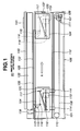
- Fig. 1 is a cross-sectional view of the image reading apparatus R1 of the first exemplary embodiment of the present invention.
- the image reading apparatus R1 includes a scanner 101 having a film scanner function.
- the scanner 101 is connected to the host computer 221 (hereinafter referred to as host PC) (see Fig. 2) by an interface cable (not illustrated), and includes an optical unit 104, platen glass 105, an electronic board 106, a pulse motor 107, an endless belt 108, pulleys 109 and 110, gear trains 111, a guide rail 112, a white reference plate 113, light source 135 for transparent original sheet, and a pressure plate 140.
- An original sheet 103 is placed between the platen glass 105 and a lower surface 102 of the light source 135 for transparent original sheet.
- the scanner 101 decides the scanning area based on a blackmark 136 inside the white reference plate 113, and scans an image of the original sheet 103.
- the optical unit 104 and the pulse motor 107 are electrically connected by cables (not illustrated).
- the optical unit 104 is disposed on a disposing unit 114, which is slidable along the guide rail 112.
- the disposing unit 114 is secured to the endless belt 108.
- the optical unit 104 is configured of a reflective original sheet light source 115, a plurality of reflective mirrors 116, 117 and 118, an imaging lens 119, and a line sensor 120 serving as an imaging sensor.
- the scanner 101 When the host PC 221 generates a scanning command, the scanner 101 starts the scanning operation.
- the scanner 101 turns on the reflective original sheet light source 115 of the optical unit 104, and the reflected lights from the original sheet are reflected by the plurality of mirrors 116, 117 and 118, and are imaged at the line sensor 120 through the imaging lens 119. Thus, one line of the image in a main scan direction is scanned.
- the endless belt 108 is driven by a force of the pulse motor 107 through rotation of the pulley 109 via the gear trains 111.
- the optical unit 104 secured to the disposing unit 114 moves along the guide rail 112 in a sub-scan direction indicated by an arrow X.
- the scanner 101 repeats the scanning operation of the line images in the main scan direction while moving the optical unit 104 in the sub-scan direction.
- the scanner 101 scans a whole surface of the platen glass 105 moving the optical unit 104 and performing the scanning to the position indicated in the dotted line of Fig. 1.
- the scanner 101 can also partially scan the original sheet on the platen glass 105 depending on the contents of the scanning command from the host PC 221.
- the scanning image area is specified by the host computer 221, and the system controller 226 (Fig. 2) of electronic substrate 106 defines a pixel area to be employed from among the outputs of the line sensors 120 in the main scan direction, and in the sub-scan direction, defines the moving area of the optical unit 104.
- the partial image on the original sheet placed on the platen glass 105 can be scanned.
- the scanner 101 turns off the reflective original sheet light source 115 of the optical unit 104, turns on the light source 135 for the transparent original sheet, moves the optical unit 104 to a transparent original sheet scanning position, and reflects the light from the light source 135 to the transparent original sheet via the plurality of mirrors 116, 117 and 118.
- the light rays are imaged at the line sensor 120 through the imaging lens 119, and thus, one line of the image in the main scan direction is scanned.
- the endless belt 108 is driven by the force of the pulse motor 107 through rotation of the pulley 109 via the gear trains 111.
- the optical unit 104 secured to the endless belt 108 via the disposing unit 114 moves along the guide rail 112 in the sub-scan direction indicated by the arrow X.
- the scanner 101 repeats the scanning operation of the line images in the main scan direction whilst moving the optical unit 104 in the sub-scan direction.
- the scanner 101 scans the whole surface of the platen glass 105 moving the optical unit 104 and performing the scanning to the position indicated in the dotted line of Fig. 1.
- the scanner 101 can also partially scan the original sheet on the platen glass 105 depending on the contents of the scanning command from the host PC 221.
- the scanning image area is specified by the host computer 221.
- the pixel area to be employed from among the outputs of the line sensors 120 is defined in the main scan direction.
- the system controller 226 (Fig. 2) of electronic substrate 106 defines the moving area of the optical unit 104.
- the system controller 226 selects a speed according to the resolution setting of the image scanning that is specified by the host PC 221, and the image is scanned.
- the operation panel 141 is disposed on the pressure plate 140.
- the operation panel 141 is provided with a display screen 501 and button 502 (refer to Fig. 5).
- the user can input the multi-cropping parameters to the scanner 101 in the operation panel 141, and the scanning operation and the like can be started.
- Fig. 2 is a block diagram showing functional components of the scanner 101 in accordance with the first exemplary embodiment.
- the scanner 101 includes the optical unit 104, the electronic board 106, the motor 107, the light source 135 for the transparent original sheet, and the motor drive circuit 225.
- the optical unit 104 has a lighting circuit 224.
- the lighting circuit 224 is configured to turn on the light source 115 for the reflective original sheet and the light source 135 for the transparent original sheet.
- the lighting circuit 22 includes a detecting unit for detecting the amount of light from the light sources. If a cold-cathode electrode tube is used for the light source 115 for the reflective original sheet and the light source 135 for the transparent original sheet, a so-called inverter circuit is constituted.
- the electronic board 106 includes a system controller 226, analog gain adjusters 227R, 227G, and 227B, an A/D converter 228, an image processing unit 229, a line buffer 230, an interface (I/F) unit 231, an offset RAM 232, a gamma RAM 233, and a system bus 234.
- the analog gain adjusters 227R, 227G, and 227B perform adjustable amplification of analog image signals output from the line sensor 120.
- the A/D converter 228 converts the analog image signals output by the variable analog gain adjusters 227R, 227G, and 227B to digital image signals.
- the image processing unit 229 performs the following image processing on the digitized image signals: offset correction, shading correction, digital gain adjustment, color balance adjustment, masking, resolution change in main and sub-scan directions, and image compression.
- the line buffer 230 temporarily stores the image data and has a general-purpose random access memory.
- the interface unit 231 communicates with the host PC 221.
- the USB interface is employed, however, other interfaces can also be employed such as IEEE1394.
- the offset RAM 232 is used as a working area for processing images. Because the RGB line sensors are arranged with pre-determined offset values and parallel to the line sensor 120, the offset RAM 232 is used to correct the offset between these RGB lines. Further, the offset RAM 232 temporarily stores various data such as shading compensation. In the present exemplary embodiment, the offset RAM 232 is configured by the general-purpose random access memory. Gamma RAM 233 stores a gamma curve, and performs gamma correction.
- the system controller 226 stores the whole sequence of the scanner 101, and performs various controls according to the commands from the host PC 221.
- the system bus 234 having an address bus and data bus connects the system controller 226, the image processing unit 229, the line buffer 230, the interface unit 231, the offset RAM 232 and the gamma RAM 233.
- the motor drive circuit 225 is employed for the pulse motor 107 and outputs an excitation switching signal of the pulse motor 107 based on the signal from the system controller 226.
- Fig. 3 is a block diagram of a typical host PC 221 used to control the scanner 101 in accordance with the first exemplary embodiment.
- the host PC221 includes a ROM 307, a RAM 308, a central processing unit 309, a disk apparatus 310, a bus 311, I/F 312, I/F 313, and an external storage device 314.
- the ROM 307 has a program to implement the operation of flowchart of Fig. 4.
- the RAM 308 provides a work area and storage area required in operating the above program.
- the central processing unit 309 performs processing in accordance with the program stored on the ROM 307.
- Bus 311 connects the components described above to enable data transfer between them.
- I/F 312 communicates with the scanner 101, which is achieved by the USB interface similar to the I/F unit 231 of the scanner 101. Other interfaces such as IEEE 1394 can also be employed.
- I/F 313 is connected to the input units 320 such as a mouse and keyboard.
- the external storage device 314 drives the external storage medium such as flexible disk or CD-ROM.
- the program can be read and downloaded from the external memory medium.
- the control program can be downloaded through the network via a network connector that is not illustrated.
- the monitor 223 displays the image cropped by the scanner 101 or the image data of the scanned original sheet.
- Fig. 4 is a flow chart that shows the scanning operation of the scanner 101 controlled by the host PC 221 in accordance with the first exemplary embodiment.
- the scanning operation of the scanner 101 includes pre-scanning that crops the plurality of original sheets placed on the platen, and main scanning that generates the image data desired by the user.
- the image data desired by the user is the data that gives the resolution, the size, the trim, and the color correction, that are desired by the user.
- the main scanning In a multifunction peripheral including a scanner and printer, the main scanning generates data to display on the monitor 223 and also to print on the storage medium.
- the user places an original sheet on the platen glass 105.
- a plurality of original sheets are placed on the platen in the case of employing the multi-cropping function.
- step S2 a scanner driver for scanning the original sheet is initialized at the host PC 211 based on the user's operation.
- step S3 various scanning setups such as scanning resolution and color mode are made based on the user's input.
- step S4 the multi-cropping is set ON based on the user's input.
- the main scanning operation can be performed if the user sets the multi-cropping function to be OFF. This step is omitted in the flow chart.
- step S5 after placing the original sheets on the platen, the user inputs the desired number X of cropped images from an operation panel 141 on the scanner 101 or from the user interface of the driver application.
- a value of the desired number X of cropped images is a whole number greater than 0.
- Fig. 5 shows the operation panel 141 on the main body of the scanner 101 with which the user inputs the desired number of cropped images.
- the operation panel 141 includes a liquid crystal panel 501 and button 502.
- the value of the desired number X of cropped images is input by the user using the button 502. In this case, the value is displayed on the liquid crystal panel 501.
- the form 601 of Fig. 6 shows an example where the desired number X of cropped images is input from the user interface of the driver application.
- a numerical value is input to the form 601 of Fig. 6 based on the user's operation and the value is set.
- step S6 the start of pre-scanning is instructed based on the user's operation.
- the scanner 101 scans the original sheet in response to this instruction.
- the host PC 211 detects the number of original sheets placed on the platen based on the scanned image data, and calculates the detected number N of cropped images (step S7).
- step S8 the desired number X of cropped images desired by the user, and the actually detected number N of cropped images, are compared.
- the multi-cropping is decided to be successful, and the dialog of "correctly cropped" is displayed on the monitor 223.
- Fig. 7 is an example of the dialog displayed on the monitor 223 in accordance with the first exemplary embodiment.
- step S11 the main scanning operation is performed (step S11), and the cropped images are respectively stored (step S12) .
- the main scanning may continue without displaying the "correctly cropped" dialog.
- Fig. 8 is an example of the dialog that prompts the user to select one of "retry pre-scanning” and “stop scanning to reset the original sheets" in accordance with the first exemplary embodiment.
- step S8 if the desired number X of cropped images and the detected number N of cropped image are different, the multi-cropping parameters are adjusted.
- Fig. 8 is one example of the dialog that prompts the user to select one of "retry pre-scanning” and “stop the main scanning to reset the original sheets", which is displayed on the monitor 223 (step S9).
- the multi-cropping parameters include threshold values such as scanning resolution and edge detection.
- step S9 in the case of retrying, the multi-cropping parameters are automatically or manually changed in step S10. Then, the process returns again to step S6, and pre-scanning operation is performed.
- the multi-cropping parameters to be changed include threshold values such as scanning resolution and edge detection as above described.
- step S9 in the case of stopping the scanning, the process returns to the start, and the user resets the original sheets. At this time, the most likely location of the detection error is displayed on the driver application screen. At the same time, the dialog prompting the user to reset the original sheets is displayed, as shown in the example of Fig. 9.
- Figs. 10, 11 and 12 show the specific examples.
- Fig. 10 describes the case where four original photographs are set by the user, and in this situation, enough spacing necessary for the detection is not given between two of the original photographs.
- the user places four photographs on the platen glass 105, and inputs "4" as the desired number X of cropped images, and the pre-scanning is performed. Since enough space required for cropping is not present between two photographs, the two photographs are cropped as one photograph. Hence, in the first pre-scanning, the detected number of cropped image N is "3".
- the dialog indicating "wrong number of cropped images" appears as shown in Fig. 8. Then, the user selects retry, and changes the multi-cropping parameters. When the re-scanning is performed once again, the detected number N of cropped images is now "4", and cropping has been accurately performed. Then, as shown in Fig. 7, the dialog indicating "correctly cropped” is displayed, the main scanning takes place, and the images are stored.
- the main scanning may continue without displaying the dialog indicating "correctly cropped".
- the cropped region where a cropping error has occurred is generally not rectangular, so that the cropped region that is not rectangular is displayed as the likely location of the cropping error by the driver application.
- the dialog shown in Fig. 9 is displayed to prompt the user to reset the photographs.
- Fig. 11 describes the case where the original photograph and the original texts are set on the platen glass 105 by the user who wishes them to be cropped and stored as one image.
- the user inputs "1" as the desired number X of cropped images, and the pre-scanning is performed.
- the photographs and texts are often cropped as different images.
- the originals are cropped as two images (the detected number N of cropped images is "2"). Because the desired number X of cropped images and the detected number N of cropped images differ from one another, the dialog showing "wrong number of cropped images" is displayed as shown in Fig. 8.
- the multi-cropping parameters (such as scanning resolution and edge detection threshold values) are adjusted, and the pre-scanning is performed again.
- the photographs and the texts are cropped as a single image, and can be stored as one image.
- the images can be combined together according to the user's intention.
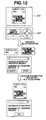
- Fig. 12 describes the case where the original sheet including the photographs and the texts, like a page on the magazine, is set by the user on the platen glass 105, who desires to correctly crop and store the original sheet as one image.
- the user inputs "1" as the desired number X of cropped images, and the pre-scanning is performed.
- the photograph portion and texts portion are cropped as separate original sheets, and are scanned and stored as two images.
- the detected number N of cropped images is "2". Therefore, the number is different from the desired number X of cropped image so that the dialog indicating "wrong number of cropped images" is displayed as shown in Fig. 8.
- the user can select retry and change multi-cropping parameters for pre-scanning once more and a single image is correctly cropped to be stored as a single image.
- Input of the desired number X of cropped images by the user is not prerequisite so that input operation can be omitted in the first pre-scanning, and the normal pre-scanning process can be performed.
- the user can decide whether to change the number of cropped images based on the scanning result (the detected number of cropped images).
- the second exemplary embodiment of the present invention is applicable to a system comprising a plurality of devices (for example, a host computer, an interface device, a scanner, a printer, and a copier).
- the storage medium that stores the program code or software that achieves the functions of the above exemplary embodiment can be supplied to the system or apparatus and a computer (CPU or MPU) of the system or the apparatus may read the program code stored in the storage media and execute the program code.
- a computer CPU or MPU
- the present exemplary embodiment shows examples of a program executable by computer.
- the user places a plurality of original sheets on a platen of an image processing apparatus.
- the program that controls the image processing apparatus provided with a multi-cropping function that automatically crops each one of the scanned original sheets includes a detecting step that detects the number of cropped images when cropping the original sheets placed on the platen, a comparing step that compares the desired number of cropped images input by the user and the detected number of cropped image, and a displaying step that displays the comparison result of the comparing step.
- the program codes read from the storage medium achieves the functions of the above exemplary embodiments.
- the storage medium that stores the program codes constitutes the present invention.
- OS operating system
- the CPU provided at the functional extension unit or the function extension card described above does a part or all of the actual processing.
- the functions of the exemplary embodiments described above are also achieved by this processing.
Landscapes
- Engineering & Computer Science (AREA)
- Multimedia (AREA)
- Signal Processing (AREA)
- Facsimile Scanning Arrangements (AREA)
- Facsimiles In General (AREA)
- Control Or Security For Electrophotography (AREA)
- Editing Of Facsimile Originals (AREA)
Applications Claiming Priority (1)
| Application Number | Priority Date | Filing Date | Title |
|---|---|---|---|
| JP2005202254A JP2007020122A (ja) | 2005-07-11 | 2005-07-11 | 画像処理装置、画像処理装置の制御方法およびプログラム |
Publications (1)
| Publication Number | Publication Date |
|---|---|
| EP1744537A1 true EP1744537A1 (de) | 2007-01-17 |
Family
ID=36811369
Family Applications (1)
| Application Number | Title | Priority Date | Filing Date |
|---|---|---|---|
| EP06253528A Withdrawn EP1744537A1 (de) | 2005-07-11 | 2006-07-05 | Vorrichtung zur Bildverarbeitung und Kontrollverfahren |
Country Status (3)
| Country | Link |
|---|---|
| US (1) | US8368942B2 (de) |
| EP (1) | EP1744537A1 (de) |
| JP (1) | JP2007020122A (de) |
Cited By (2)
| Publication number | Priority date | Publication date | Assignee | Title |
|---|---|---|---|---|
| GB2511194A (en) * | 2012-12-26 | 2014-08-27 | Canon Kk | Image processing apparatus, image capturing apparatus, image processing method, program, and storage medium |
| CN107040680A (zh) * | 2015-12-01 | 2017-08-11 | 夏普株式会社 | 图像读取装置 |
Families Citing this family (25)
| Publication number | Priority date | Publication date | Assignee | Title |
|---|---|---|---|---|
| KR100777462B1 (ko) * | 2005-01-19 | 2007-11-21 | 삼성전자주식회사 | 스캐닝장치, 그것을 구비하는 스캐닝시스템 및 스캐닝방법 |
| KR101201227B1 (ko) * | 2007-11-20 | 2012-11-13 | 삼성전자주식회사 | 화상형성장치 및 멀티 크롭 화상형성방법 |
| JP4500865B2 (ja) * | 2008-04-30 | 2010-07-14 | キヤノン株式会社 | 画像処理装置、画像処理方法、プログラム及び記憶媒体 |
| JP4653194B2 (ja) * | 2008-04-30 | 2011-03-16 | キヤノン株式会社 | 画像処理装置、画像処理装置の制御方法、プログラム及びコンピュータ読取可能な記憶媒体 |
| JP5241631B2 (ja) | 2008-07-04 | 2013-07-17 | キヤノン株式会社 | 画像処理方法、画像処理装置及びプログラム |
| US9547799B2 (en) * | 2008-07-17 | 2017-01-17 | Sharp Laboratories Of America, Inc. | Methods and systems for content-boundary detection |
| JP5222126B2 (ja) * | 2008-12-25 | 2013-06-26 | キヤノン株式会社 | 画像処理方法、画像処理装置及びプログラム |
| JP5222127B2 (ja) | 2008-12-25 | 2013-06-26 | キヤノン株式会社 | 画像処理装置、画像処理方法及びプログラム |
| US20110249307A1 (en) * | 2009-10-16 | 2011-10-13 | E. I. Du Pont De Nemours And Company | Hologram and associated methods of fabrication thereof and use in security/authentication applications |
| US8873864B2 (en) * | 2009-12-16 | 2014-10-28 | Sharp Laboratories Of America, Inc. | Methods and systems for automatic content-boundary detection |
| JP5665397B2 (ja) * | 2010-07-12 | 2015-02-04 | キヤノン株式会社 | 画像読取方法、読取制御装置、及びプログラム |
| JP5758025B1 (ja) * | 2014-04-30 | 2015-08-05 | 株式会社Pfu | 画像読取装置 |
| JP6539844B2 (ja) * | 2015-03-27 | 2019-07-10 | 株式会社日本デジタル研究所 | 証憑イメージ取得方法およびこれを用いた会計処理システム |
| US20170155792A1 (en) * | 2015-12-01 | 2017-06-01 | Sharp Kabushiki Kaisha | Image reading apparatus |
| JP6562823B2 (ja) | 2015-12-01 | 2019-08-21 | シャープ株式会社 | 画像読取装置 |
| JP6562822B2 (ja) | 2015-12-01 | 2019-08-21 | シャープ株式会社 | 画像読取装置 |
| JP6528727B2 (ja) * | 2016-06-08 | 2019-06-12 | 京セラドキュメントソリューションズ株式会社 | 画像読取装置、画像形成装置、調整値設定方法 |
| JP6837347B2 (ja) | 2017-02-15 | 2021-03-03 | シャープ株式会社 | 画像読取装置および画像読取方法 |
| JP6986946B2 (ja) * | 2017-12-13 | 2021-12-22 | シャープ株式会社 | 原稿読取装置 |
| JP7130436B2 (ja) * | 2018-05-25 | 2022-09-05 | キヤノン株式会社 | マルチクロップ処理を行う画像処理装置、マルチクロップ処理によって原稿単位の画像を生成する方法、および、プログラム |
| JP7155705B2 (ja) * | 2018-07-20 | 2022-10-19 | 京セラドキュメントソリューションズ株式会社 | 画像形成装置 |
| JP7155845B2 (ja) * | 2018-10-10 | 2022-10-19 | 京セラドキュメントソリューションズ株式会社 | 画像読取装置及び画像形成装置 |
| JP6752337B2 (ja) * | 2019-07-23 | 2020-09-09 | シャープ株式会社 | 画像読取装置 |
| JP7415634B2 (ja) * | 2020-02-10 | 2024-01-17 | 富士フイルムビジネスイノベーション株式会社 | 情報処理装置及びプログラム |
| JP2021136523A (ja) * | 2020-02-26 | 2021-09-13 | 京セラドキュメントソリューションズ株式会社 | 画像読取装置、画像形成装置、原稿領域検出方法 |
Citations (6)
| Publication number | Priority date | Publication date | Assignee | Title |
|---|---|---|---|---|
| US4823289A (en) * | 1984-06-08 | 1989-04-18 | Dainippon Screen Mfg. Co., Ltd. | Positioning originals on an original scanning drum of an image reproducing system |
| US4947269A (en) * | 1986-03-31 | 1990-08-07 | Canon Kabushiki Kaisha | Image reproduction apparatus capable of dividing an image into parts for reproduction on respective sheets |
| US5974199A (en) * | 1997-03-31 | 1999-10-26 | Eastman Kodak Company | Method for scanning and detecting multiple photographs and removing edge artifacts |
| US6304683B1 (en) * | 1997-03-07 | 2001-10-16 | Dainippon Screen Mfg. Ltd. | Image scanning apparatus, method of scanning images, and recording medium for realizing the method |
| US20010048447A1 (en) * | 2000-06-05 | 2001-12-06 | Fuji Photo Film Co., Ltd. | Image croppin and synthesizing method, and imaging apparatus |
| US20020048413A1 (en) * | 2000-08-23 | 2002-04-25 | Fuji Photo Film Co., Ltd. | Imaging system |
Family Cites Families (9)
| Publication number | Priority date | Publication date | Assignee | Title |
|---|---|---|---|---|
| JPH10322542A (ja) * | 1997-05-14 | 1998-12-04 | Ricoh Co Ltd | 画像形成装置 |
| JPH11203411A (ja) * | 1998-01-20 | 1999-07-30 | Fuji Xerox Co Ltd | 文書読み取り装置 |
| DE60045263D1 (de) * | 1999-09-14 | 2010-12-30 | Toshiba Kk | Vorrichtung und Verfahren zur Gesichtsphotographie |
| JP2002010059A (ja) * | 2000-06-20 | 2002-01-11 | Sharp Corp | 画像処理装置 |
| JP2004260457A (ja) * | 2003-02-25 | 2004-09-16 | Canon Inc | 画像読取装置 |
| US6956587B1 (en) * | 2003-10-30 | 2005-10-18 | Microsoft Corporation | Method of automatically cropping and adjusting scanned images |
| JP2005311766A (ja) * | 2004-04-22 | 2005-11-04 | Fuji Xerox Co Ltd | 画像読み取り装置 |
| US20050281462A1 (en) * | 2004-06-16 | 2005-12-22 | Jayati Ghosh | System and method of automated processing of multiple microarray images |
| US7945116B2 (en) * | 2007-08-20 | 2011-05-17 | Ancestry.Com Operations Inc. | Computer-assisted image cropping for book scans |
-
2005
- 2005-07-11 JP JP2005202254A patent/JP2007020122A/ja active Pending
-
2006
- 2006-07-05 EP EP06253528A patent/EP1744537A1/de not_active Withdrawn
- 2006-07-07 US US11/482,885 patent/US8368942B2/en not_active Expired - Fee Related
Patent Citations (6)
| Publication number | Priority date | Publication date | Assignee | Title |
|---|---|---|---|---|
| US4823289A (en) * | 1984-06-08 | 1989-04-18 | Dainippon Screen Mfg. Co., Ltd. | Positioning originals on an original scanning drum of an image reproducing system |
| US4947269A (en) * | 1986-03-31 | 1990-08-07 | Canon Kabushiki Kaisha | Image reproduction apparatus capable of dividing an image into parts for reproduction on respective sheets |
| US6304683B1 (en) * | 1997-03-07 | 2001-10-16 | Dainippon Screen Mfg. Ltd. | Image scanning apparatus, method of scanning images, and recording medium for realizing the method |
| US5974199A (en) * | 1997-03-31 | 1999-10-26 | Eastman Kodak Company | Method for scanning and detecting multiple photographs and removing edge artifacts |
| US20010048447A1 (en) * | 2000-06-05 | 2001-12-06 | Fuji Photo Film Co., Ltd. | Image croppin and synthesizing method, and imaging apparatus |
| US20020048413A1 (en) * | 2000-08-23 | 2002-04-25 | Fuji Photo Film Co., Ltd. | Imaging system |
Cited By (4)
| Publication number | Priority date | Publication date | Assignee | Title |
|---|---|---|---|---|
| GB2511194A (en) * | 2012-12-26 | 2014-08-27 | Canon Kk | Image processing apparatus, image capturing apparatus, image processing method, program, and storage medium |
| GB2511194B (en) * | 2012-12-26 | 2017-06-14 | Canon Kk | Image processing apparatus, image capturing apparatus, image processing method, program, and storage medium |
| US10115178B2 (en) | 2012-12-26 | 2018-10-30 | Canon Kabushiki Kaisha | Image processing apparatus, image capturing apparatus, image processing method, and storage medium |
| CN107040680A (zh) * | 2015-12-01 | 2017-08-11 | 夏普株式会社 | 图像读取装置 |
Also Published As
| Publication number | Publication date |
|---|---|
| JP2007020122A (ja) | 2007-01-25 |
| US20070013974A1 (en) | 2007-01-18 |
| US8368942B2 (en) | 2013-02-05 |
Similar Documents
| Publication | Publication Date | Title |
|---|---|---|
| US8368942B2 (en) | Image processing apparatus and its program and control method | |
| JP4930731B2 (ja) | 複合プリンタ及びふちなし印刷方法 | |
| US8023158B2 (en) | Image processing system and image processing method | |
| US8102575B2 (en) | Image processing apparatus and method | |
| EP0497178B1 (de) | Bildeingabegerät | |
| JP4541951B2 (ja) | 画像処理装置、画像処理方法およびプログラム | |
| US20230145962A1 (en) | Image reading apparatus and control method for image reading | |
| US11758064B2 (en) | Reading device and image forming apparatus | |
| EP1445934A1 (de) | Bildabtastungvorrichtung mit einer Einstellungsfähigkeit von der Bildabtastungsposition | |
| JP4203817B2 (ja) | 複合プリンタおよびスキャンイメージ複写方法 | |
| US5050007A (en) | Image-scanning apparatus and method therefor | |
| US20050219632A1 (en) | Image processing system and image processing method | |
| US11882248B2 (en) | Reading device and image forming apparatus | |
| US7002706B2 (en) | Image reading apparatus and method | |
| JP2003219085A (ja) | 画像読み取り方法、画像読み取り装置及び制御装置 | |
| JP2007208617A (ja) | 画像読取装置および画像読取方法 | |
| JP3048613B2 (ja) | 画像読取装置 | |
| US20110286049A1 (en) | Image reading apparatus | |
| JP3812745B2 (ja) | 複合プリンタおよびスキャンイメージ複写方法 | |
| JP2007324648A (ja) | 画像読取システムおよび画像読取システムの制御方法 | |
| JPH04292064A (ja) | 画像読取り装置 | |
| JPH11298686A (ja) | 画像読み取り装置 | |
| JP2000224390A (ja) | 画像読み取り装置 | |
| JP2001169096A (ja) | 画像読取方法及び装置並びに記憶媒体 | |
| JP2006311081A (ja) | 画像読取装置および画像読取装置の制御方法 |
Legal Events
| Date | Code | Title | Description |
|---|---|---|---|
| PUAI | Public reference made under article 153(3) epc to a published international application that has entered the european phase |
Free format text: ORIGINAL CODE: 0009012 |
|
| AK | Designated contracting states |
Kind code of ref document: A1 Designated state(s): AT BE BG CH CY CZ DE DK EE ES FI FR GB GR HU IE IS IT LI LT LU LV MC NL PL PT RO SE SI SK TR |
|
| AX | Request for extension of the european patent |
Extension state: AL BA HR MK YU |
|
| 17P | Request for examination filed |
Effective date: 20070717 |
|
| AKX | Designation fees paid |
Designated state(s): DE FR GB IT |
|
| STAA | Information on the status of an ep patent application or granted ep patent |
Free format text: STATUS: THE APPLICATION HAS BEEN WITHDRAWN |
|
| 18W | Application withdrawn |
Effective date: 20160202 |