EP1754595A2 - Module d'entraînement pour presse et procédé pour fournir une gamme de presses - Google Patents
Module d'entraînement pour presse et procédé pour fournir une gamme de presses Download PDFInfo
- Publication number
- EP1754595A2 EP1754595A2 EP06013812A EP06013812A EP1754595A2 EP 1754595 A2 EP1754595 A2 EP 1754595A2 EP 06013812 A EP06013812 A EP 06013812A EP 06013812 A EP06013812 A EP 06013812A EP 1754595 A2 EP1754595 A2 EP 1754595A2
- Authority
- EP
- European Patent Office
- Prior art keywords
- press
- drive
- drive module
- module according
- force
- Prior art date
- Legal status (The legal status is an assumption and is not a legal conclusion. Google has not performed a legal analysis and makes no representation as to the accuracy of the status listed.)
- Granted
Links
Images


Classifications
-
- B—PERFORMING OPERATIONS; TRANSPORTING
- B30—PRESSES
- B30B—PRESSES IN GENERAL
- B30B1/00—Presses, using a press ram, characterised by the features of the drive therefor, pressure being transmitted directly, or through simple thrust or tension members only, to the press ram or platen
-
- B—PERFORMING OPERATIONS; TRANSPORTING
- B30—PRESSES
- B30B—PRESSES IN GENERAL
- B30B1/00—Presses, using a press ram, characterised by the features of the drive therefor, pressure being transmitted directly, or through simple thrust or tension members only, to the press ram or platen
- B30B1/26—Presses, using a press ram, characterised by the features of the drive therefor, pressure being transmitted directly, or through simple thrust or tension members only, to the press ram or platen by cams, eccentrics, or cranks
- B30B1/265—Presses, using a press ram, characterised by the features of the drive therefor, pressure being transmitted directly, or through simple thrust or tension members only, to the press ram or platen by cams, eccentrics, or cranks using a fluid connecting unit between drive shaft and press ram
-
- B—PERFORMING OPERATIONS; TRANSPORTING
- B30—PRESSES
- B30B—PRESSES IN GENERAL
- B30B1/00—Presses, using a press ram, characterised by the features of the drive therefor, pressure being transmitted directly, or through simple thrust or tension members only, to the press ram or platen
- B30B1/32—Presses, using a press ram, characterised by the features of the drive therefor, pressure being transmitted directly, or through simple thrust or tension members only, to the press ram or platen by plungers under fluid pressure
- B30B1/323—Presses, using a press ram, characterised by the features of the drive therefor, pressure being transmitted directly, or through simple thrust or tension members only, to the press ram or platen by plungers under fluid pressure using low pressure long stroke opening and closing means, and high pressure short stroke cylinder means
Definitions
- the invention relates to a press drive module and a method for providing a press series.
- the plungers of large mechanical presses were usually connected by connecting rods to an eccentric drive, which in turn was driven by a drive motor and a flywheel at a relatively uniform speed. Because such drives have certain Efforts have been made to drive the plunger, for example by means of a servo motor, whereby the path / time curve of the plunger movement could then be adjusted relatively freely by the corresponding control of the servomotor.
- the disclosed DE 41 09 796 C2 the drive of the plunger via a connecting rod and an eccentric, which is driven by a servomotor.
- the servomotor can run forwards and backwards and can be specifically accelerated and decelerated.
- the drive of the plunger is about a toggle gear, the toggle mechanism in turn is driven by a connecting rod and an eccentric by a servo motor. Even with this configuration, desired path / time profiles can be set within wide limits.
- the U.S. Patent No. 6,041,699 also discloses a ram drive a press by means of servo motor via toggle mechanism. To drive the toggle mechanism serve a fferspindelgetriebe and servomotors.
- non-linear gear such as toggle mechanism or eccentric
- the plunger movement is often not as freely adjustable as desired.
- the entire forming force must be applied by the servomotor.
- non-linear gearboxes such as toggle mechanisms or eccentric gearboxes
- the drive of the press ram by means of screw jack allows on the one hand a very revealing determination of the path / time history of the plunger movement, but it limits the achievable before reaching bottom dead center maximum force.
- the press drive module according to the invention combines in itself two drive devices which have different force / displacement characteristics. This is preferably achieved by using different drive concepts. Thus, not only within wide limits arbitrary path / time curves of the plunger movement can be achieved but it is also possible to use for each part of the path / time curve in each case that drive means having the just fitting characteristic. For example, a weak but rather fast drive can be used for the passage of characteristic sections, which only require a small actuating force. For the execution of forming operations, which are generally fast but comparatively slow, but high To carry out force can be used that drive device which applies a high force at relatively low operating speed.
- the two drive means united in the press drive module e.g. be formed by servomotors with downstream transmission and different transmission ratios.
- the servomotors can be the same or different. Due to the different reduction, the servomotors work, although act on the same output, at one and the same output speed in different characteristic areas, which increases the overall design freedom in terms of achievable path / time profiles of the plunger movement. In addition, the scope is increased in terms of achievable forces.
- press drive module is thus versatile and can serve as a basis for the equipment of different sizes presses of a press series.
- a large range of desired forces and driving speeds can be achieved with the given press drive module.
- the press drive modules if the non-constructive or other Praktikabilticiansberichte, be connected in parallel in principle any number.
- a press ram can be driven by one or more identical press drive modules, which can be provided within a press series of different performance classes. It is also possible to provide drive modules in different power classes, with the drive modules being consistent within each power class.
- a press line can be constructed, the first stage (drawing stage) has a larger number of press drive modules while the subsequent, usually less loaded, press stages are equipped with correspondingly fewer press drive modules.
- the individual stages of the press line thereby different ram-way / time courses and different ram strokes can be driven.
- the performance classes of the provided press drive modules having a uniform maximum lift are exponentially stepped.
- the power classes of the drive modules are determined, for example, by the maximum forces to be applied by the drive modules.
- the drive modules of different power classes preferably also have the same maximum lift. This allows the combination of press drive modules of different power classes with each other for the common drive of a plunger of a press.
- the press drive modules of the different performance classes preferably have the same maximum travel speeds. This facilitates as well as the uniformly fixed maximum stroke, the parallel arrangement for common drive one and the same plunger.
- the press drive modules each form structural units, which are preferably formed separately from the press. They can thus be prefabricated and installed as a finished assembly in appropriately prepared press racks.
- the assembly of the press drive modules can be separated from the assembly of the press frame. This is especially important for large presses. With this concept, a manufacturing simplification can go hand in hand and the construction time of presses can be shortened.
- At least one of the drive means of the press drive modules includes a variable ratio transmission.
- This may be, for example, a toggle mechanism, an eccentric, a combination thereof or any other transmission with variable ratio.
- gearboxes come into question, which deliver in their dead or reversal point an infinitely large force transmission or in other words a fixed support point by the force to be sustained is no longer determined by the driving servo motor but only by the load limits of the transmission.
- This has significance, for example, in solutions in which the drive devices are structurally arranged in series.
- a servo-driven eccentric drive can be connected in series with a hydraulic cylinder.
- the hydraulic drive means can be used to drive the ram for workpiece deformation slowly with great force. If the eccentric is in dead center, the servomotor remains substantially free of forces. It thus succeeds with relatively weak servomotors and a relatively short-stroke hydraulic device on the one hand to generate a large movement stroke for the plunger and on the other hand a high forming force.
- both drive devices can be activated overlapping.
- these are preferably activated jointly in each case, wherein they complement each other in terms of their force development.
- the press drive module has its own base frame, which takes over the leadership between the two drives. It may further be provided a housing in which the at least two drive means are housed. Alternatively, however, it is also possible to integrate the press drive module at least partially into the press frame. For example, one of the power take-offs may be formed as part of a press header or plunger.
- the press drive modules is preferably an energy store, for example a mechanical, electrical or hydraulic energy storage associated. This minimizes the supply network load.
- the press drive module can be executed in principle in a variety of ways. However, its characteristic feature in almost all embodiments is that the introduction of force from the at least two drive means belonging to the module takes place at the plunger and / or at the head piece at a common location.
- the press drive modules provide a fixed numerical relationship between the number of first drive means and the number of second drive means. For example, when a plunger is driven only by drive modules of a single power class, e.g. each have a first drive means and each having a second drive means, are for the ram drive total, regardless of the number of press drive modules as many first drive means as second drive means available.
- press drive modules are designed with, for example, a first drive device and two or more eg three second drive devices and used for ram drive, in this example three times as many second drive devices are present as first drive devices. If press drive modules of different power classes and with different ratios between the numbers of the first and the second drive means are used, these numerical ratios apply in groups for the press drive modules of the respectively considered performance class.
- the drive means of the press drive module are preferably mechanically independent of each other, i. they can be controlled independently of each other.
- the synchronization of their working movement or the coordination thereof is preferably carried out electrically.
- the individual modules or even only their drive devices or drives can be selectively controlled depending on the design or optionally also switchable and / or force-controlled. They preferably allow a continuous adjustment of the plunger stroke during operation and a variation of the path / time characteristic of the plunger movement during operation.
- Force sensors can be provided in order to avoid overloading, in particular in the case of drive modules or drive devices driven in a controlled manner.
- the individual drive devices of a press drive module may be coupled together via coupling devices of arbitrarily controllable type or overrunning clutches.
- the slow drive means can be decoupled from the high-speed, when a ram travel is to go through quickly. The slow drive is then coupled again when the fast drive has moved the plunger back to the Abkuppelstelle and a slower plunger movement a large force is required.
- a press 1 is illustrated schematically.
- the press 1 is preferably a large press, for example a body press. It can form a press stage of a press line or a transfer press.
- the press 1 has a press frame 2, to which at least one table 3 belongs.
- the press 1 has press stands 4, 5 and a head piece 6 connecting the uprights 4, 5.
- a plunger 7 is linear, slidably mounted in the present embodiment, vertically.
- a subdivision tool 8 and an upper tool 9 subdivided pressing tool 10 is arranged.
- unified press drive modules 11, 12, 13 are arranged.
- the press drive modules can generate at least one pushing or pushing force to move the plunger 7 downwards. If necessary, they can also be designed so that they can lift the plunger 7. In a particular case of very large presses whose plunger 7 have a considerable weight, attacks on the plunger 7 in addition to a not illustrated in Figure 1 weight compensation device, for example in the form of a pressurized pneumatic cylinder, which serves to compensate for the plunger weight.
- the press drive modules 11 to 13 are connected to a control device 14, which controls the operation of the press drive modules 11 to 13.
- the press drive modules 11 to 13 via the corresponding lines 15, 16, 17 are acted upon to effect the adjusting movement with energy, for example in the form of electric energy or a pressurized fluid or both.
- energy for example in the form of electric energy or a pressurized fluid or both.
- the lines 15, 16, 17 can also be designed such that information supplied by the press drive modules 11 to 13, for example, position information, is reported back to the control device 14.
- the lines 15, 16, 17 are to be understood as cables, as fluid lines, cable bundles, fluid line bundles or bundles of lines, which contain both electrical lines and fluid lines.
- the press 1 can be provided with one or more position sensors 18, 19 for detecting the position of the plunger, which are also connected to the control device 14.
- FIG 2 illustrates the press drive module 11, which is representative of the other two press drive modules 12, 13. It can be provided between the head piece 6 and the plunger 7 to increase the pressing force of the press 1 more equal trained press drive modules.
- the press drive module 11 is separately illustrated schematically in FIG. 2 in an exemplary embodiment. It contains two drive devices 20, 21, which generate the forces acting between drives 22, 23 and the drives 22, 23 move against each other.
- the power take-offs 22, 23 have, for example, the form of mechanical connecting means, As flanges, couplings or the like and are, as Figure 1 illustrates, respectively connected to the head piece 6 and the plunger 7.
- the outputs 22, 23 are connection means for transmitting power between the press drive module 11 and the head piece 6 or the plunger 7 in the direction of movement of the plunger 7 and thus in the direction of action of the press drive module 11.
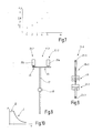
- the two drive devices 20, 21 of the press drive module 11 have different force / displacement characteristics and movement characteristics I and II, as shown in FIG.
- the first drive device 20 whose characteristic curve forms the characteristic load I is designed as a servo drive device. It has a servo motor 25 held on a frame 24, which drives an eccentric 27 or a corresponding crank drive via a gear drive 26. The crank is rotatable about an axis 28 and mounted in the frame 24. The frame 24 is directly connected to the output 22.
- the eccentric 27 drives via a connecting rod 29 an intermediate plunger 30, which is guided in the frame 24.
- the intermediate plunger 30 is connected to the second drive means 21, whose characteristic curve forms the characteristic branch II and which is in the form of a hydraulic cylinder 31, in which a displaceably mounted piston 32 is arranged.
- the hydraulic cylinder 31 is directly connected to the second output 23. In it, two working chambers 33, 34 are limited, which are controlled acted upon by hydraulic fluid.
- the servomotor 25 is provided with a control line 35, which forms part of the line 15. Besides, he can do one Position sensor, which sends 36 sensor signals via a sensor line.
- the line 15 may include a hydraulic line 37, which serves to control the working chamber 34. Another hydraulic line for driving the hydraulic chamber 33 is not illustrated, but may also be present.
- To control the drive device 21 serve, for example, a hydraulic valve 38, a pressure source, which is not illustrated, and a pressure accumulator 39, which is shown only schematically in Figure 2.
- the press drive module 11 and the press 1 described so far operate as follows:
- the press drive modules 11, 12, 13 are controlled synchronously by the control device 14 in order to generate an up and down movement of the plunger 7.
- the traversed by the plunger 7 path / time curve is similar, for example, a sine curve with much flattened lower shaft. While the upper part of this curve means a low-force opening and closing of the pressing tool 10, the lower part of the displacement / time curve refers to a small lifting portion above the bottom dead center of the plunger 7, where the actual material deformation takes place. For example, if the stroke is 500 mm, the force to be transmitted to the plunger 7 in the upper 400 mm is usually relatively small, while it may be greater in the lower 100 mm. Depending on the application, the ratios may be shifted towards larger or smaller parts of the route.
- the press drive module 11 uses the drive device 20 to travel sections of the total stroke quickly, but to hurry through with relatively small forces.
- the yielded by the drive device 20 stroke of the intermediate plunger 30 is less than the desired total stroke.
- the first drive means 20 for example, the upper 400 mm travel path of the ram travel can be traversed.
- the transmission ratio between the servomotor 25 and the intermediate plunger 30 is constantly changing. The reduction is approaching infinity when approaching the upper and lower dead center. This means that the ratio between the distance between the intermediate plunger 30 and the angle of rotation of the servomotor 25 is 0 for a short time.
- These positions which may also be referred to as an extended position, represent support positions of the upper drive device 20. In these positions, the upper drive device 20 can support very large forces.
- the second drive device 21 is activated. Hydraulic fluid now flows into the working chamber 34 to carry out the last 100 mm working stroke.
- the path / time profile of the plunger movement is adjustable by influencing the mass flow of the inflowing hydraulic fluid within wide limits.
- the force that can be generated between the drives 22, 23 corresponds to the force of the second drive device 21. In principle, this can be substantially greater than the force otherwise applied by the first drive device 20, since this is in the extended or neutral position, so that the servomotor 25 remains largely free of forces.
- a position sensor 40 may be provided which monitors the position of the piston 32.
- the position sensor 40 may be connected to the control device 14 via a sensor line 41 belonging to the line 15.
- the drive devices 20, 21 can, as described, be activated one after another in time. It is also possible to activate them at least slightly overlapping in time, i. to begin with the operation of the drive means 21 when the drive means 20 approaches its bottom dead center. This ensures a smooth, jerk-free transition of the drive movements.
- the drive device 21 can act in addition, when the speed of the intermediate plunger 30 approaches the value zero when approaching the lower stretched position.
- the proposed press drive module has the advantage that on the one hand can be used with relatively small servo motors and on the other hand, only relatively small hydraulic fluid flows are required to operate the second drive means 21.
- the two drive devices 20, 21 use in the presented embodiment different drive concepts that even emanate from different types of energy (electric energy and hydraulic energy). However, it is also possible to combine two drive devices 20-1, 21-1 with each other, use the same drive energy, as Figure 2 illustrates.
- the press drive module 11-1 shown there is based on two servomotors 25a, 25b, both of which actuate a respective screw jack.
- the screw jack of the drive device 20-1 acts directly to the lower output 23-1 while its servomotor 25a is directly connected to the upper output 22-1.
- the servomotor 25b and its screw jack gear act via a toggle mechanism 42, which is arranged between the upper output 22-1 and the lower output 23-1.
- both drive devices 20-1, 21-1 are thus arranged in parallel. Nevertheless, the two drive devices 20-1, 21-1 complement each other due to their different force / displacement characteristics.
- the drive device 20-1 increases the usable lift to values that can not be achieved with the drive device 21-1 alone.
- the difference between the characteristics is here effected by the fact that the drive device 20-1 acts directly and the drive device 21-1 indirectly via a toggle mechanism.
- the press drive modules 11, 12 can be used to build presses of different sizes.
- Figure 4 illustrates a press 1 ', the plunger 7 is driven by only two press drive modules 11, 12. These are identical to the drive modules 11, 12 of the press 1 according to FIG. The above description thus applies accordingly.
- the drive means 21 are buffered via the pressure accumulator 39, so that a corresponding network load is made uniform.
- the servomotors 25 can also be operated from a buffer 43, for example in the form of a motor generator set, a capacitor bank or other suitable memory.
- the control device 14 is also connected to a network 44, from which it draws relatively even energy, for example, for recharging the buffer 43.
- press drive modules 11, 12 of the embodiments described above are constructed as separate units with or without their own housing, which can be installed as prefabricated units in presses.
- Figures 5 and 6 illustrate a modified embodiment using combined and unified press drive modules 11, 12 partially integrated with the presses 1a, 1b.
- the presses 1a, 1b reference is made to the above description on the basis of the introduced reference numbers.
- the drive modules 11, 12 of the presses 1a, 1b of FIGS. 5 and 6 belonging to a common series are combined in the form of a servo-motor-driven eccentric or crank drive and hydraulic cylinder.
- the drive means 20, 21 are not combined into a separate unit, but part of the head piece 6 and the plunger 7.
- the module concept described above is taken over insofar as the drive means 20, 21 are formed identical to each other in all presses of the illustrated series.
- the comparatively smaller press 1a contains only one press drive module 11 while the press 1b contains two or more drive modules 11, 12 and so on.
- the illustrated press series thus differs in terms of their drives only by the number of press drive modules used, but not by their structure.
- press drive modules of different power or power classes or Hubtex An example is illustrated in FIG. It shows five different press drive module types whose performances are, for example, exponential. You can, for example, by the factor 2 differ from each other.
- FIG. 8 illustrates in the most schematic way a further embodiment of a press drive module 11-2 with two drive devices 20-2, 21-2 with servomotors 25b, 25c. These work with different ratios via gear drives 45, 46 on a common threaded spindle 47 which drives a spindle nut 48 linearly reciprocating.
- the servo motor 25b is capable of transmitting relatively large torques to the lead screw 47 while the servo motor 25c transmits smaller moments but slows down at a given spindle speed.
- the servo motor 25c can generate very fast adjusting movements while the servomotor 25b can generate very high pressing forces.
- the servomotor 25b runs at high speeds, where he himself could no longer deliver corresponding torque.
- the scope of the servo motor drives for press ram is expanded.
- the solution is simple and requires no couplings per se.
- a switchable clutch or a freewheel can be arranged between the gear drive 45 and the servo motor 25b. It is also possible to provide two counter-rotating freewheels, which can be blocked as required.
- FIG. 9 shows a further variant of a press drive module 11-3.
- This is based on two hydraulic drive devices, 20-3, 21-3, which are arranged in series between the drives 22-3, 23-3.
- the hydraulic drive device 20-3 is designed for long strokes with relatively little force.
- the hydraulic drive device 21-3 is designed for short strokes with high force.
- a braking device 49 is provided, with which the comparatively weaker drive device 20-3 is firmly braked. In this way, the higher force emanating from the drive device 21-3 upon activation can be supported and thus transmitted to the output 22-3.
- the illustrated press drive module 11-3 thus consumes much less hydraulic fluid at high speed than a correspondingly large hydraulic cylinder and is able to generate the required high driving forces on a part of the movement curve of the plunger.
- press drive modules which allow a unified press design.
- the presses of a series are equipped with always the same press drive modules, whereby the pressing force of the presses is varied only by adjusting the number of press drive modules.
- the press drive modules each contain two drive devices which interact in parallel or serially and have different characteristics. In particular, they have different maximum travel speeds and different maximum forces. They can also be designed differently in terms of their positioning and path resolution. This concept not only allows standardization of presses of different performance classes within a series but also the largely free determination of path / time curves of the plunger and thus ultimately a freer design of workpieces, especially body parts.
Landscapes
- Engineering & Computer Science (AREA)
- Mechanical Engineering (AREA)
- Physics & Mathematics (AREA)
- Fluid Mechanics (AREA)
- Press Drives And Press Lines (AREA)
- Control Of Presses (AREA)
Applications Claiming Priority (1)
| Application Number | Priority Date | Filing Date | Title |
|---|---|---|---|
| DE10538583 | 2005-08-16 |
Publications (3)
| Publication Number | Publication Date |
|---|---|
| EP1754595A2 true EP1754595A2 (fr) | 2007-02-21 |
| EP1754595A3 EP1754595A3 (fr) | 2011-11-16 |
| EP1754595B1 EP1754595B1 (fr) | 2014-08-20 |
Family
ID=37434204
Family Applications (1)
| Application Number | Title | Priority Date | Filing Date |
|---|---|---|---|
| EP06013812.0A Not-in-force EP1754595B1 (fr) | 2005-08-16 | 2006-07-04 | Module d'entraînement pour presse et procédé pour fournir une gamme de presses |
Country Status (2)
| Country | Link |
|---|---|
| EP (1) | EP1754595B1 (fr) |
| ES (1) | ES2508791T3 (fr) |
Cited By (7)
| Publication number | Priority date | Publication date | Assignee | Title |
|---|---|---|---|---|
| DE102008038264A1 (de) * | 2008-08-15 | 2010-02-18 | H & T Produktions Technologie Gmbh | Elektrisch angetriebene Presse |
| WO2011038921A1 (fr) * | 2009-10-01 | 2011-04-07 | Haco N.V. | Procédé pour déplacer une unité de façonnage d'une machine |
| ITBO20110146A1 (it) * | 2011-03-23 | 2012-09-24 | Gigant Italia S R L | Pressa per deformazione plastica |
| DE102011101132A1 (de) | 2011-07-08 | 2013-01-24 | Sms Meer Gmbh | Antrieb für eine Presse |
| DE102009012111B4 (de) * | 2009-03-06 | 2014-10-02 | Andritz Technology And Asset Management Gmbh | Mechanische Umformpresse und Verfahren zur Betätigung dieser Umformpresse |
| DE112008000462B4 (de) * | 2007-03-14 | 2016-01-28 | Ihi Corporation | Presse |
| EP3024646B1 (fr) * | 2013-07-23 | 2022-05-25 | Modus One GmbH | Module de force et système de pressage modulaire |
Citations (5)
| Publication number | Priority date | Publication date | Assignee | Title |
|---|---|---|---|---|
| DE4319289A1 (de) | 1993-06-11 | 1994-12-15 | Bernd Hoerner | Presse, insbesondere Verformungspresse |
| US6041699A (en) | 1995-12-15 | 2000-03-28 | Amada Mfg America Inc. | Ram driving device and press machine using same |
| JP2000343283A (ja) | 1999-05-31 | 2000-12-12 | Yamada Dobby Co Ltd | ねじプレス機のスライド制御装置 |
| DE4109796C2 (de) | 1991-03-26 | 2002-05-29 | Georg Burger | Einrichtung zum Pressen, Biegen und/oder Stanzen |
| US6708609B1 (en) | 1999-07-29 | 2004-03-23 | Schuler Pressen Gmbh & Co. Kg | Press product line |
Family Cites Families (5)
| Publication number | Priority date | Publication date | Assignee | Title |
|---|---|---|---|---|
| DE3507327A1 (de) * | 1985-03-01 | 1986-09-04 | Jörg 8607 Hollfeld Lange | Exzenter-hydraulikpresse |
| DE19640440C2 (de) * | 1996-09-30 | 1998-07-16 | Fraunhofer Ges Forschung | Antriebsvorrichtung für einen Pressenstößel einer Umformpresse |
| JP2000326095A (ja) * | 1999-05-19 | 2000-11-28 | Yamada Dobby Co Ltd | プレス機 |
| DE10139029C5 (de) * | 2001-08-15 | 2008-09-04 | Müller Weingarten AG | Pressenantrieb |
| DE10158861C2 (de) * | 2001-11-30 | 2003-12-04 | Schuler Automation Gmbh & Co | Vorrichtung zum Bewegen eines Stößels einer Presse |
-
2006
- 2006-07-04 ES ES06013812.0T patent/ES2508791T3/es active Active
- 2006-07-04 EP EP06013812.0A patent/EP1754595B1/fr not_active Not-in-force
Patent Citations (5)
| Publication number | Priority date | Publication date | Assignee | Title |
|---|---|---|---|---|
| DE4109796C2 (de) | 1991-03-26 | 2002-05-29 | Georg Burger | Einrichtung zum Pressen, Biegen und/oder Stanzen |
| DE4319289A1 (de) | 1993-06-11 | 1994-12-15 | Bernd Hoerner | Presse, insbesondere Verformungspresse |
| US6041699A (en) | 1995-12-15 | 2000-03-28 | Amada Mfg America Inc. | Ram driving device and press machine using same |
| JP2000343283A (ja) | 1999-05-31 | 2000-12-12 | Yamada Dobby Co Ltd | ねじプレス機のスライド制御装置 |
| US6708609B1 (en) | 1999-07-29 | 2004-03-23 | Schuler Pressen Gmbh & Co. Kg | Press product line |
Cited By (8)
| Publication number | Priority date | Publication date | Assignee | Title |
|---|---|---|---|---|
| DE112008000462B4 (de) * | 2007-03-14 | 2016-01-28 | Ihi Corporation | Presse |
| DE102008038264A1 (de) * | 2008-08-15 | 2010-02-18 | H & T Produktions Technologie Gmbh | Elektrisch angetriebene Presse |
| DE102009012111B4 (de) * | 2009-03-06 | 2014-10-02 | Andritz Technology And Asset Management Gmbh | Mechanische Umformpresse und Verfahren zur Betätigung dieser Umformpresse |
| WO2011038921A1 (fr) * | 2009-10-01 | 2011-04-07 | Haco N.V. | Procédé pour déplacer une unité de façonnage d'une machine |
| ITBO20110146A1 (it) * | 2011-03-23 | 2012-09-24 | Gigant Italia S R L | Pressa per deformazione plastica |
| DE102011101132A1 (de) | 2011-07-08 | 2013-01-24 | Sms Meer Gmbh | Antrieb für eine Presse |
| DE102011101132B4 (de) * | 2011-07-08 | 2013-08-22 | Sms Meer Gmbh | Antrieb für eine Presse |
| EP3024646B1 (fr) * | 2013-07-23 | 2022-05-25 | Modus One GmbH | Module de force et système de pressage modulaire |
Also Published As
| Publication number | Publication date |
|---|---|
| EP1754595A3 (fr) | 2011-11-16 |
| ES2508791T3 (es) | 2014-10-16 |
| EP1754595B1 (fr) | 2014-08-20 |
Similar Documents
| Publication | Publication Date | Title |
|---|---|---|
| DE102005038583B4 (de) | Pressen-Antriebsmodul und Verfahren zur Bereitstellung einer Pressenbaureihe | |
| DE102004009256B4 (de) | Mechanische Mehrservopresse | |
| DE102011000473B4 (de) | Pressmaschine und Verfahren zum Pressen von Werkstücken | |
| EP2480405B1 (fr) | Entrainement hydraulique precontraint dote d'une pompe a vitesse variable | |
| DE102011016669B4 (de) | Verfahren zum Betreiben einer Presse mit Unterantrieb und danach betriebene Presse | |
| DE102006058630B4 (de) | Elektrohydraulische Pressenhaupt- oder Nebenantriebseinrichtung, insbesondere elektrohydraulischer Ziehkissenantrieb | |
| EP2637852A1 (fr) | Essieu hydraulique | |
| EP2420681B1 (fr) | Entraînement linéaire hydraulique | |
| DE102010060103A1 (de) | Ziehpresse mit dynamisch optimierter Blechhaltung | |
| DE102005001878B3 (de) | Servopresse mit Kniehebelgetriebe | |
| EP0929396B1 (fr) | Procede de controle de la vitesse d'un coulisseau de presse dans une presse de formage, et dispositif de commande de ce coulisseau | |
| DE102007040286A1 (de) | Hydraulische Presse | |
| EP1754595B1 (fr) | Module d'entraînement pour presse et procédé pour fournir une gamme de presses | |
| WO2023041476A1 (fr) | Système d'entraînement hydraulique doté d'une unité pompe 4q | |
| DE102011113624B4 (de) | Modulares Antriebssystem für eine Umformmaschine | |
| EP2367676B1 (fr) | Procédé de régulation d'une presse à forger | |
| EP2280178A1 (fr) | Dispositif et méthode de contôle pour un ensemble piston-cylindre | |
| DE4218952B4 (de) | Hydraulischer Antrieb für eine Presse, insbesondere für eine Blechformpresse | |
| EP1252010A1 (fr) | Presse | |
| DE102009008367B4 (de) | Vorrichtung und Verfahren zur Betätigung einer bewegbaren Komponente | |
| DE102018203367A1 (de) | Hydrostatischer Linearantrieb | |
| DE102014101616B4 (de) | Hydraulisches Ziehkissen einer Ziehpresse und Verfahren zum Betreiben des hydraulischen Ziehkissens | |
| EP1930149A1 (fr) | Entrainement pour presse à excentrique | |
| DE102004030678A1 (de) | Ziehkissen-Vorrichtung mit Hybrid-Antrieb | |
| AT523856B1 (de) | Formgebungsmaschine mit einem geschlossenen, hydraulischen Antriebssystem |
Legal Events
| Date | Code | Title | Description |
|---|---|---|---|
| PUAI | Public reference made under article 153(3) epc to a published international application that has entered the european phase |
Free format text: ORIGINAL CODE: 0009012 |
|
| AK | Designated contracting states |
Kind code of ref document: A2 Designated state(s): AT BE BG CH CY CZ DE DK EE ES FI FR GB GR HU IE IS IT LI LT LU LV MC NL PL PT RO SE SI SK TR |
|
| AX | Request for extension of the european patent |
Extension state: AL BA HR MK YU |
|
| RIC1 | Information provided on ipc code assigned before grant |
Ipc: B30B 15/00 20060101ALI20110722BHEP Ipc: B30B 1/00 20060101AFI20110722BHEP |
|
| PUAL | Search report despatched |
Free format text: ORIGINAL CODE: 0009013 |
|
| AK | Designated contracting states |
Kind code of ref document: A3 Designated state(s): AT BE BG CH CY CZ DE DK EE ES FI FR GB GR HU IE IS IT LI LT LU LV MC NL PL PT RO SE SI SK TR |
|
| AX | Request for extension of the european patent |
Extension state: AL BA HR MK RS |
|
| RIC1 | Information provided on ipc code assigned before grant |
Ipc: B30B 1/32 20060101ALI20111012BHEP Ipc: B30B 1/26 20060101ALI20111012BHEP Ipc: B30B 1/00 20060101AFI20111012BHEP |
|
| 17P | Request for examination filed |
Effective date: 20120514 |
|
| RIC1 | Information provided on ipc code assigned before grant |
Ipc: B30B 1/00 20060101AFI20120611BHEP Ipc: B30B 1/32 20060101ALI20120611BHEP Ipc: B30B 1/26 20060101ALI20120611BHEP |
|
| AKX | Designation fees paid |
Designated state(s): AT BE BG CH CY CZ DE DK EE ES FI FR GB GR HU IE IS IT LI LT LU LV MC NL PL PT RO SE SI SK TR |
|
| 17Q | First examination report despatched |
Effective date: 20120724 |
|
| GRAP | Despatch of communication of intention to grant a patent |
Free format text: ORIGINAL CODE: EPIDOSNIGR1 |
|
| INTG | Intention to grant announced |
Effective date: 20140410 |
|
| GRAS | Grant fee paid |
Free format text: ORIGINAL CODE: EPIDOSNIGR3 |
|
| GRAA | (expected) grant |
Free format text: ORIGINAL CODE: 0009210 |
|
| RAP1 | Party data changed (applicant data changed or rights of an application transferred) |
Owner name: SCHULER PRESSEN GMBH |
|
| AK | Designated contracting states |
Kind code of ref document: B1 Designated state(s): AT BE BG CH CY CZ DE DK EE ES FI FR GB GR HU IE IS IT LI LT LU LV MC NL PL PT RO SE SI SK TR |
|
| REG | Reference to a national code |
Ref country code: GB Ref legal event code: FG4D Free format text: NOT ENGLISH |
|
| REG | Reference to a national code |
Ref country code: CH Ref legal event code: EP |
|
| REG | Reference to a national code |
Ref country code: AT Ref legal event code: REF Ref document number: 683206 Country of ref document: AT Kind code of ref document: T Effective date: 20140915 |
|
| REG | Reference to a national code |
Ref country code: IE Ref legal event code: FG4D Free format text: LANGUAGE OF EP DOCUMENT: GERMAN |
|
| REG | Reference to a national code |
Ref country code: DE Ref legal event code: R096 Ref document number: 502006013917 Country of ref document: DE Effective date: 20141002 |
|
| REG | Reference to a national code |
Ref country code: ES Ref legal event code: FG2A Ref document number: 2508791 Country of ref document: ES Kind code of ref document: T3 Effective date: 20141016 |
|
| REG | Reference to a national code |
Ref country code: NL Ref legal event code: VDEP Effective date: 20140820 |
|
| REG | Reference to a national code |
Ref country code: LT Ref legal event code: MG4D |
|
| PG25 | Lapsed in a contracting state [announced via postgrant information from national office to epo] |
Ref country code: BG Free format text: LAPSE BECAUSE OF FAILURE TO SUBMIT A TRANSLATION OF THE DESCRIPTION OR TO PAY THE FEE WITHIN THE PRESCRIBED TIME-LIMIT Effective date: 20141120 Ref country code: LT Free format text: LAPSE BECAUSE OF FAILURE TO SUBMIT A TRANSLATION OF THE DESCRIPTION OR TO PAY THE FEE WITHIN THE PRESCRIBED TIME-LIMIT Effective date: 20140820 Ref country code: SE Free format text: LAPSE BECAUSE OF FAILURE TO SUBMIT A TRANSLATION OF THE DESCRIPTION OR TO PAY THE FEE WITHIN THE PRESCRIBED TIME-LIMIT Effective date: 20140820 Ref country code: FI Free format text: LAPSE BECAUSE OF FAILURE TO SUBMIT A TRANSLATION OF THE DESCRIPTION OR TO PAY THE FEE WITHIN THE PRESCRIBED TIME-LIMIT Effective date: 20140820 Ref country code: PT Free format text: LAPSE BECAUSE OF FAILURE TO SUBMIT A TRANSLATION OF THE DESCRIPTION OR TO PAY THE FEE WITHIN THE PRESCRIBED TIME-LIMIT Effective date: 20141222 Ref country code: GR Free format text: LAPSE BECAUSE OF FAILURE TO SUBMIT A TRANSLATION OF THE DESCRIPTION OR TO PAY THE FEE WITHIN THE PRESCRIBED TIME-LIMIT Effective date: 20141121 |
|
| PG25 | Lapsed in a contracting state [announced via postgrant information from national office to epo] |
Ref country code: IS Free format text: LAPSE BECAUSE OF FAILURE TO SUBMIT A TRANSLATION OF THE DESCRIPTION OR TO PAY THE FEE WITHIN THE PRESCRIBED TIME-LIMIT Effective date: 20141220 Ref country code: LV Free format text: LAPSE BECAUSE OF FAILURE TO SUBMIT A TRANSLATION OF THE DESCRIPTION OR TO PAY THE FEE WITHIN THE PRESCRIBED TIME-LIMIT Effective date: 20140820 |
|
| PG25 | Lapsed in a contracting state [announced via postgrant information from national office to epo] |
Ref country code: NL Free format text: LAPSE BECAUSE OF FAILURE TO SUBMIT A TRANSLATION OF THE DESCRIPTION OR TO PAY THE FEE WITHIN THE PRESCRIBED TIME-LIMIT Effective date: 20140820 |
|
| PG25 | Lapsed in a contracting state [announced via postgrant information from national office to epo] |
Ref country code: RO Free format text: LAPSE BECAUSE OF FAILURE TO SUBMIT A TRANSLATION OF THE DESCRIPTION OR TO PAY THE FEE WITHIN THE PRESCRIBED TIME-LIMIT Effective date: 20140820 Ref country code: DK Free format text: LAPSE BECAUSE OF FAILURE TO SUBMIT A TRANSLATION OF THE DESCRIPTION OR TO PAY THE FEE WITHIN THE PRESCRIBED TIME-LIMIT Effective date: 20140820 Ref country code: EE Free format text: LAPSE BECAUSE OF FAILURE TO SUBMIT A TRANSLATION OF THE DESCRIPTION OR TO PAY THE FEE WITHIN THE PRESCRIBED TIME-LIMIT Effective date: 20140820 Ref country code: CZ Free format text: LAPSE BECAUSE OF FAILURE TO SUBMIT A TRANSLATION OF THE DESCRIPTION OR TO PAY THE FEE WITHIN THE PRESCRIBED TIME-LIMIT Effective date: 20140820 Ref country code: SK Free format text: LAPSE BECAUSE OF FAILURE TO SUBMIT A TRANSLATION OF THE DESCRIPTION OR TO PAY THE FEE WITHIN THE PRESCRIBED TIME-LIMIT Effective date: 20140820 |
|
| REG | Reference to a national code |
Ref country code: DE Ref legal event code: R097 Ref document number: 502006013917 Country of ref document: DE |
|
| PG25 | Lapsed in a contracting state [announced via postgrant information from national office to epo] |
Ref country code: PL Free format text: LAPSE BECAUSE OF FAILURE TO SUBMIT A TRANSLATION OF THE DESCRIPTION OR TO PAY THE FEE WITHIN THE PRESCRIBED TIME-LIMIT Effective date: 20140820 |
|
| PLBE | No opposition filed within time limit |
Free format text: ORIGINAL CODE: 0009261 |
|
| STAA | Information on the status of an ep patent application or granted ep patent |
Free format text: STATUS: NO OPPOSITION FILED WITHIN TIME LIMIT |
|
| 26N | No opposition filed |
Effective date: 20150521 |
|
| PG25 | Lapsed in a contracting state [announced via postgrant information from national office to epo] |
Ref country code: SI Free format text: LAPSE BECAUSE OF FAILURE TO SUBMIT A TRANSLATION OF THE DESCRIPTION OR TO PAY THE FEE WITHIN THE PRESCRIBED TIME-LIMIT Effective date: 20140820 |
|
| PG25 | Lapsed in a contracting state [announced via postgrant information from national office to epo] |
Ref country code: MC Free format text: LAPSE BECAUSE OF FAILURE TO SUBMIT A TRANSLATION OF THE DESCRIPTION OR TO PAY THE FEE WITHIN THE PRESCRIBED TIME-LIMIT Effective date: 20140820 |
|
| REG | Reference to a national code |
Ref country code: CH Ref legal event code: PL |
|
| GBPC | Gb: european patent ceased through non-payment of renewal fee |
Effective date: 20150704 |
|
| PG25 | Lapsed in a contracting state [announced via postgrant information from national office to epo] |
Ref country code: LU Free format text: LAPSE BECAUSE OF FAILURE TO SUBMIT A TRANSLATION OF THE DESCRIPTION OR TO PAY THE FEE WITHIN THE PRESCRIBED TIME-LIMIT Effective date: 20150704 |
|
| REG | Reference to a national code |
Ref country code: IE Ref legal event code: MM4A |
|
| PG25 | Lapsed in a contracting state [announced via postgrant information from national office to epo] |
Ref country code: LI Free format text: LAPSE BECAUSE OF NON-PAYMENT OF DUE FEES Effective date: 20150731 Ref country code: CH Free format text: LAPSE BECAUSE OF NON-PAYMENT OF DUE FEES Effective date: 20150731 Ref country code: GB Free format text: LAPSE BECAUSE OF NON-PAYMENT OF DUE FEES Effective date: 20150704 |
|
| REG | Reference to a national code |
Ref country code: FR Ref legal event code: ST Effective date: 20160331 |
|
| PG25 | Lapsed in a contracting state [announced via postgrant information from national office to epo] |
Ref country code: FR Free format text: LAPSE BECAUSE OF NON-PAYMENT OF DUE FEES Effective date: 20150731 |
|
| PG25 | Lapsed in a contracting state [announced via postgrant information from national office to epo] |
Ref country code: IE Free format text: LAPSE BECAUSE OF NON-PAYMENT OF DUE FEES Effective date: 20150704 |
|
| REG | Reference to a national code |
Ref country code: AT Ref legal event code: MM01 Ref document number: 683206 Country of ref document: AT Kind code of ref document: T Effective date: 20150704 |
|
| PGFP | Annual fee paid to national office [announced via postgrant information from national office to epo] |
Ref country code: DE Payment date: 20160616 Year of fee payment: 11 Ref country code: IT Payment date: 20160721 Year of fee payment: 11 |
|
| PG25 | Lapsed in a contracting state [announced via postgrant information from national office to epo] |
Ref country code: AT Free format text: LAPSE BECAUSE OF NON-PAYMENT OF DUE FEES Effective date: 20150704 |
|
| PGFP | Annual fee paid to national office [announced via postgrant information from national office to epo] |
Ref country code: ES Payment date: 20160722 Year of fee payment: 11 |
|
| PG25 | Lapsed in a contracting state [announced via postgrant information from national office to epo] |
Ref country code: HU Free format text: LAPSE BECAUSE OF FAILURE TO SUBMIT A TRANSLATION OF THE DESCRIPTION OR TO PAY THE FEE WITHIN THE PRESCRIBED TIME-LIMIT; INVALID AB INITIO Effective date: 20060704 |
|
| PG25 | Lapsed in a contracting state [announced via postgrant information from national office to epo] |
Ref country code: CY Free format text: LAPSE BECAUSE OF FAILURE TO SUBMIT A TRANSLATION OF THE DESCRIPTION OR TO PAY THE FEE WITHIN THE PRESCRIBED TIME-LIMIT Effective date: 20140820 |
|
| PG25 | Lapsed in a contracting state [announced via postgrant information from national office to epo] |
Ref country code: BE Free format text: LAPSE BECAUSE OF NON-PAYMENT OF DUE FEES Effective date: 20150731 |
|
| PG25 | Lapsed in a contracting state [announced via postgrant information from national office to epo] |
Ref country code: TR Free format text: LAPSE BECAUSE OF FAILURE TO SUBMIT A TRANSLATION OF THE DESCRIPTION OR TO PAY THE FEE WITHIN THE PRESCRIBED TIME-LIMIT Effective date: 20140820 |
|
| REG | Reference to a national code |
Ref country code: DE Ref legal event code: R119 Ref document number: 502006013917 Country of ref document: DE |
|
| PG25 | Lapsed in a contracting state [announced via postgrant information from national office to epo] |
Ref country code: DE Free format text: LAPSE BECAUSE OF NON-PAYMENT OF DUE FEES Effective date: 20180201 |
|
| PG25 | Lapsed in a contracting state [announced via postgrant information from national office to epo] |
Ref country code: IT Free format text: LAPSE BECAUSE OF NON-PAYMENT OF DUE FEES Effective date: 20170704 |
|
| REG | Reference to a national code |
Ref country code: ES Ref legal event code: FD2A Effective date: 20181107 |
|
| PG25 | Lapsed in a contracting state [announced via postgrant information from national office to epo] |
Ref country code: ES Free format text: LAPSE BECAUSE OF NON-PAYMENT OF DUE FEES Effective date: 20170705 |