EP1758526B1 - Vorrichtung zur herstellung einer härtbaren masse - Google Patents
Vorrichtung zur herstellung einer härtbaren masse Download PDFInfo
- Publication number
- EP1758526B1 EP1758526B1 EP05752716A EP05752716A EP1758526B1 EP 1758526 B1 EP1758526 B1 EP 1758526B1 EP 05752716 A EP05752716 A EP 05752716A EP 05752716 A EP05752716 A EP 05752716A EP 1758526 B1 EP1758526 B1 EP 1758526B1
- Authority
- EP
- European Patent Office
- Prior art keywords
- mixing
- container
- mass
- space
- piston means
- Prior art date
- Legal status (The legal status is an assumption and is not a legal conclusion. Google has not performed a legal analysis and makes no representation as to the accuracy of the status listed.)
- Expired - Lifetime
Links
Images



Classifications
-
- B—PERFORMING OPERATIONS; TRANSPORTING
- B01—PHYSICAL OR CHEMICAL PROCESSES OR APPARATUS IN GENERAL
- B01F—MIXING, e.g. DISSOLVING, EMULSIFYING OR DISPERSING
- B01F33/00—Other mixers; Mixing plants; Combinations of mixers
- B01F33/50—Movable or transportable mixing devices or plants
- B01F33/501—Movable mixing devices, i.e. readily shifted or displaced from one place to another, e.g. portable during use
-
- A—HUMAN NECESSITIES
- A61—MEDICAL OR VETERINARY SCIENCE; HYGIENE
- A61F—FILTERS IMPLANTABLE INTO BLOOD VESSELS; PROSTHESES; DEVICES PROVIDING PATENCY TO, OR PREVENTING COLLAPSING OF, TUBULAR STRUCTURES OF THE BODY, e.g. STENTS; ORTHOPAEDIC, NURSING OR CONTRACEPTIVE DEVICES; FOMENTATION; TREATMENT OR PROTECTION OF EYES OR EARS; BANDAGES, DRESSINGS OR ABSORBENT PADS; FIRST-AID KITS
- A61F2/00—Filters implantable into blood vessels; Prostheses, i.e. artificial substitutes or replacements for parts of the body; Appliances for connecting them with the body; Devices providing patency to, or preventing collapsing of, tubular structures of the body, e.g. stents
- A61F2/02—Prostheses implantable into the body
- A61F2/30—Joints
- A61F2/46—Special tools for implanting artificial joints
-
- B—PERFORMING OPERATIONS; TRANSPORTING
- B01—PHYSICAL OR CHEMICAL PROCESSES OR APPARATUS IN GENERAL
- B01F—MIXING, e.g. DISSOLVING, EMULSIFYING OR DISPERSING
- B01F33/00—Other mixers; Mixing plants; Combinations of mixers
- B01F33/50—Movable or transportable mixing devices or plants
- B01F33/501—Movable mixing devices, i.e. readily shifted or displaced from one place to another, e.g. portable during use
- B01F33/5011—Movable mixing devices, i.e. readily shifted or displaced from one place to another, e.g. portable during use portable during use, e.g. hand-held
- B01F33/50112—Movable mixing devices, i.e. readily shifted or displaced from one place to another, e.g. portable during use portable during use, e.g. hand-held of the syringe or cartridge type
-
- A—HUMAN NECESSITIES
- A61—MEDICAL OR VETERINARY SCIENCE; HYGIENE
- A61B—DIAGNOSIS; SURGERY; IDENTIFICATION
- A61B17/00—Surgical instruments, devices or methods
- A61B17/56—Surgical instruments or methods for treatment of bones or joints; Devices specially adapted therefor
- A61B17/58—Surgical instruments or methods for treatment of bones or joints; Devices specially adapted therefor for osteosynthesis, e.g. bone plates, screws or setting implements
- A61B17/88—Osteosynthesis instruments; Methods or means for implanting or extracting internal or external fixation devices
- A61B17/8802—Equipment for handling bone cement or other fluid fillers
- A61B17/8805—Equipment for handling bone cement or other fluid fillers for introducing fluid filler into bone or extracting it
- A61B17/8816—Equipment for handling bone cement or other fluid fillers for introducing fluid filler into bone or extracting it characterised by the conduit, e.g. tube, along which fluid flows into the body or by conduit connections
-
- A—HUMAN NECESSITIES
- A61—MEDICAL OR VETERINARY SCIENCE; HYGIENE
- A61B—DIAGNOSIS; SURGERY; IDENTIFICATION
- A61B17/00—Surgical instruments, devices or methods
- A61B17/56—Surgical instruments or methods for treatment of bones or joints; Devices specially adapted therefor
- A61B17/58—Surgical instruments or methods for treatment of bones or joints; Devices specially adapted therefor for osteosynthesis, e.g. bone plates, screws or setting implements
- A61B17/88—Osteosynthesis instruments; Methods or means for implanting or extracting internal or external fixation devices
- A61B17/8802—Equipment for handling bone cement or other fluid fillers
- A61B17/8805—Equipment for handling bone cement or other fluid fillers for introducing fluid filler into bone or extracting it
- A61B17/8827—Equipment for handling bone cement or other fluid fillers for introducing fluid filler into bone or extracting it with filtering, degassing, venting or pressure relief means
-
- A—HUMAN NECESSITIES
- A61—MEDICAL OR VETERINARY SCIENCE; HYGIENE
- A61B—DIAGNOSIS; SURGERY; IDENTIFICATION
- A61B17/00—Surgical instruments, devices or methods
- A61B17/56—Surgical instruments or methods for treatment of bones or joints; Devices specially adapted therefor
- A61B17/58—Surgical instruments or methods for treatment of bones or joints; Devices specially adapted therefor for osteosynthesis, e.g. bone plates, screws or setting implements
- A61B17/88—Osteosynthesis instruments; Methods or means for implanting or extracting internal or external fixation devices
- A61B17/8802—Equipment for handling bone cement or other fluid fillers
- A61B17/8833—Osteosynthesis tools specially adapted for handling bone cement or fluid fillers; Means for supplying bone cement or fluid fillers to introducing tools, e.g. cartridge handling means
-
- A—HUMAN NECESSITIES
- A61—MEDICAL OR VETERINARY SCIENCE; HYGIENE
- A61M—DEVICES FOR INTRODUCING MEDIA INTO, OR ONTO, THE BODY; DEVICES FOR TRANSDUCING BODY MEDIA OR FOR TAKING MEDIA FROM THE BODY; DEVICES FOR PRODUCING OR ENDING SLEEP OR STUPOR
- A61M5/00—Devices for bringing media into the body in a subcutaneous, intra-vascular or intramuscular way; Accessories therefor, e.g. filling or cleaning devices, arm-rests
- A61M5/178—Syringes
- A61M5/31—Details
- A61M5/315—Pistons; Piston-rods; Guiding, blocking or restricting the movement of the rod or piston; Appliances on the rod for facilitating dosing ; Dosing mechanisms
-
- B—PERFORMING OPERATIONS; TRANSPORTING
- B01—PHYSICAL OR CHEMICAL PROCESSES OR APPARATUS IN GENERAL
- B01F—MIXING, e.g. DISSOLVING, EMULSIFYING OR DISPERSING
- B01F31/00—Mixers with shaking, oscillating, or vibrating mechanisms
-
- B—PERFORMING OPERATIONS; TRANSPORTING
- B01—PHYSICAL OR CHEMICAL PROCESSES OR APPARATUS IN GENERAL
- B01F—MIXING, e.g. DISSOLVING, EMULSIFYING OR DISPERSING
- B01F31/00—Mixers with shaking, oscillating, or vibrating mechanisms
- B01F31/44—Mixers with shaking, oscillating, or vibrating mechanisms with stirrers performing an oscillatory, vibratory or shaking movement
- B01F31/441—Mixers with shaking, oscillating, or vibrating mechanisms with stirrers performing an oscillatory, vibratory or shaking movement performing a rectilinear reciprocating movement
-
- B—PERFORMING OPERATIONS; TRANSPORTING
- B01—PHYSICAL OR CHEMICAL PROCESSES OR APPARATUS IN GENERAL
- B01F—MIXING, e.g. DISSOLVING, EMULSIFYING OR DISPERSING
- B01F33/00—Other mixers; Mixing plants; Combinations of mixers
- B01F33/70—Mixers specially adapted for working at sub- or super-atmospheric pressure, e.g. combined with de-foaming
-
- B—PERFORMING OPERATIONS; TRANSPORTING
- B01—PHYSICAL OR CHEMICAL PROCESSES OR APPARATUS IN GENERAL
- B01F—MIXING, e.g. DISSOLVING, EMULSIFYING OR DISPERSING
- B01F35/00—Accessories for mixers; Auxiliary operations or auxiliary devices; Parts or details of general application
- B01F35/71—Feed mechanisms
- B01F35/713—Feed mechanisms comprising breaking packages or parts thereof, e.g. piercing or opening sealing elements between compartments or cartridges
-
- B—PERFORMING OPERATIONS; TRANSPORTING
- B01—PHYSICAL OR CHEMICAL PROCESSES OR APPARATUS IN GENERAL
- B01F—MIXING, e.g. DISSOLVING, EMULSIFYING OR DISPERSING
- B01F35/00—Accessories for mixers; Auxiliary operations or auxiliary devices; Parts or details of general application
- B01F35/75—Discharge mechanisms
- B01F35/754—Discharge mechanisms characterised by the means for discharging the components from the mixer
- B01F35/75425—Discharge mechanisms characterised by the means for discharging the components from the mixer using pistons or plungers
- B01F35/754251—Discharge mechanisms characterised by the means for discharging the components from the mixer using pistons or plungers reciprocating in the mixing receptacle
-
- B—PERFORMING OPERATIONS; TRANSPORTING
- B29—WORKING OF PLASTICS; WORKING OF SUBSTANCES IN A PLASTIC STATE IN GENERAL
- B29B—PREPARATION OR PRETREATMENT OF THE MATERIAL TO BE SHAPED; MAKING GRANULES OR PREFORMS; RECOVERY OF PLASTICS OR OTHER CONSTITUENTS OF WASTE MATERIAL CONTAINING PLASTICS
- B29B7/00—Mixing; Kneading
- B29B7/002—Methods
- B29B7/005—Methods for mixing in batches
-
- B—PERFORMING OPERATIONS; TRANSPORTING
- B29—WORKING OF PLASTICS; WORKING OF SUBSTANCES IN A PLASTIC STATE IN GENERAL
- B29B—PREPARATION OR PRETREATMENT OF THE MATERIAL TO BE SHAPED; MAKING GRANULES OR PREFORMS; RECOVERY OF PLASTICS OR OTHER CONSTITUENTS OF WASTE MATERIAL CONTAINING PLASTICS
- B29B7/00—Mixing; Kneading
- B29B7/02—Mixing; Kneading non-continuous, with mechanical mixing or kneading devices, i.e. batch type
- B29B7/22—Component parts, details or accessories; Auxiliary operations
- B29B7/26—Component parts, details or accessories; Auxiliary operations for discharging, e.g. doors
-
- A—HUMAN NECESSITIES
- A61—MEDICAL OR VETERINARY SCIENCE; HYGIENE
- A61F—FILTERS IMPLANTABLE INTO BLOOD VESSELS; PROSTHESES; DEVICES PROVIDING PATENCY TO, OR PREVENTING COLLAPSING OF, TUBULAR STRUCTURES OF THE BODY, e.g. STENTS; ORTHOPAEDIC, NURSING OR CONTRACEPTIVE DEVICES; FOMENTATION; TREATMENT OR PROTECTION OF EYES OR EARS; BANDAGES, DRESSINGS OR ABSORBENT PADS; FIRST-AID KITS
- A61F2/00—Filters implantable into blood vessels; Prostheses, i.e. artificial substitutes or replacements for parts of the body; Appliances for connecting them with the body; Devices providing patency to, or preventing collapsing of, tubular structures of the body, e.g. stents
- A61F2/02—Prostheses implantable into the body
- A61F2/30—Joints
- A61F2/46—Special tools for implanting artificial joints
- A61F2002/4685—Special tools for implanting artificial joints by means of vacuum
-
- A—HUMAN NECESSITIES
- A61—MEDICAL OR VETERINARY SCIENCE; HYGIENE
- A61M—DEVICES FOR INTRODUCING MEDIA INTO, OR ONTO, THE BODY; DEVICES FOR TRANSDUCING BODY MEDIA OR FOR TAKING MEDIA FROM THE BODY; DEVICES FOR PRODUCING OR ENDING SLEEP OR STUPOR
- A61M5/00—Devices for bringing media into the body in a subcutaneous, intra-vascular or intramuscular way; Accessories therefor, e.g. filling or cleaning devices, arm-rests
- A61M5/178—Syringes
- A61M5/31—Details
- A61M5/315—Pistons; Piston-rods; Guiding, blocking or restricting the movement of the rod or piston; Appliances on the rod for facilitating dosing ; Dosing mechanisms
- A61M5/31596—Pistons; Piston-rods; Guiding, blocking or restricting the movement of the rod or piston; Appliances on the rod for facilitating dosing ; Dosing mechanisms comprising means for injection of two or more media, e.g. by mixing
-
- B—PERFORMING OPERATIONS; TRANSPORTING
- B01—PHYSICAL OR CHEMICAL PROCESSES OR APPARATUS IN GENERAL
- B01F—MIXING, e.g. DISSOLVING, EMULSIFYING OR DISPERSING
- B01F2101/00—Mixing characterised by the nature of the mixed materials or by the application field
- B01F2101/20—Mixing of ingredients for bone cement
Definitions
- the present invention relates to a device for producing a hardenable mass, preferably a bone substitute and/or bone reinforcing material or bone cement or a similar material, wherein a mixing container has a mixing space in which at least one powder and at least one liquid component are mixed to provide the hardenable mass.
- a piston means is provided in the mixing space of the mixing container, which piston means can be retained relative to the mixing container and be released such that it can move in relation thereto in a direction towards at least one opening through which mixed mass can pass out of the mixing container, wherein at least one means which is rotatable relative to the mixing container cooperates with the piston means for, in a retaining position, retaining said piston means relative to the mixing container and, by rotation to a release position, releasing the piston means such that said piston means can move towards the opening.
- Vertebroplasty is a percutaneous injection of bone cement into a vertebra in order to alleviate pain in a compression fracture caused by osteoporosis. Vertebroplasty was performed for the first time in France in 1984 and ten years later in the USA. Kyphoplasty means balloon expansion in a collapsed vertebra for, if possible, reducing the risk for further collapse of the vertebra and provide a cavity which is filled with bone cement.
- Kyphoplasty is regarded as experimental in Europe, but has recently been approved by the FDA for treatment of pathological fractures together with polymeric bone cements.
- the drawback with kyphoplasty is that this method requires general anaesthesia. Vertebroplasty however, can be performed in a surgery in fluoroscopy while administering sedatives and analgesics. Both methods give satisfactory pain relief in more than 75% of the cases. Early treatment of vertebra compression with vertebroplasty is still discussed even if satisfactory pain relief can be provided. It is recommended to wait at least six weeks before vertebroplasty is performed. While waiting, pain killing treatment is tested. Early treatment with vertebroplasty however, can be considered if there is a risk for complications causing immobilization or if the pain is severe. A principal object with vertebroplasty is except pain relief to prevent further collapse of vertebra. For identifying fractures, MR can be used besides common X-ray, said MR also showing oedema in the bone marrow and fracture gaps in the vertebra.
- Vertebroplasty is performed with the patient lying on his or her stomach or on the side during intraveneous sedation and pain relief and under control by a physician.
- a needle is inserted into a mandrine in the vertebra during fluoroscopy via a transpedicular or posteolateral inlet.
- the needle shall be positioned in the centre line, preferably in the fore or anterior part of the vertebra.
- injection of cement is carried through.
- Another needle is often necessary for symmetric filling of the vertebra.
- the injection of cement is carefully supervised via TV-fluoroscopy and if leakage occurs outside the limits of the vertebra, the injection is interrupted.
- the required volume for adequate pain relief is small, about 2-3 ml.
- the object of the present invention is to provide a simple device permitting simple handling in connection with vertebroplasty and similar. This is arrived at by providing the device defined above with the characterizing features of subsequent claim 1.
- the device 1 illustrated in the drawings is adapted for producing a hardenable mass 2 such as bone substitute and/or bone reinforcing material or bone cement or similar material.
- This mass 2 shall be fed and/or sucked out of the device 1 and comprises a mixing container 3 of e.g. cylindrical shape.
- the mixing container 3 defines a mixing space 4 in which at least one powder component 5 and at least one liquid component 6 are mixed to produce the hardenable mass 2.
- a piston means 7 which is adapted to be retained relative to the mixing container 3 during a mixing step and thereafter released such that it can move in the mixing space 4 relative to the mixing container 3.
- a rotatable means 8 which in a retaining position P1 retains the piston means 7 relative to the mixing container 3 and which by rotation from the retaining position P1 to a release position P2 can be released relative to the mixing container 3, whereby the piston means 7 can move in the mixing space 4.
- the piston means 7 and the rotatable means 8 are preferably directly or indirectly interconnected.
- the device 1 preferably but not necessarily comprises a mixing means 9 which is provided for mixing the powder and liquid components 5, 6 with each other until the hardenable mass 2 has been produced. Then, the mass 2 can be stirred with the mixing means 9 if this is appropriate or necessary.
- the mixing means 9 may comprise an elongated member 10, e.g. a hollow or solid rod, which extends into the mixing space 4 and which at an inner end within the mixing space 4 has a mixing disc 11 with axial holes 12 passing through said disc. At an outer end outside the mixing space 4, the elongated member 10 is provided with an operating handle 13 for operating the mixing means 9.
- the mixing/stirring can be carried through in a known manner by moving the mixing means 9 back and forth in the mixing space 4 and preferably also rotating it relative to said mixing space 4.
- the piston means 7 preferably has an axial hole 14 extending therethrough and by means of which the elongated member 10 of the mixing means 9 extends into the mixing space 4.
- the elongated member 10 cooperates with the piston means 7 through one or more sealing rings 15 or similar, such that a sealing is provided between said members.
- the elongated member 10 and the hole 14 of the piston means 7 are adapted to each other such that said elongated member 10 can be moved and rotated relative to the piston means 7.
- At least one outer sealing 16 or similar is provided on the piston means 7 for cooperation with the inner side of the mixing container 3 such that a sealing is defined between the piston means 7 and said inner side.
- the outer sealing ring 16 is preferably designed such that it removes mass 2 which deposits on the inner side of the mixing container 3 when it moves in the mixing space 4.
- the piston means 7 may also have an opening 17 with at least one filter 18.
- the opening 17 is adapted to let out gases from the mixing space 4 and the filter 18 is adapted to prevent the components 5 and/or 6 and the mixed mass 2 from forcing its way out of the mixing space 4 through the opening 17.
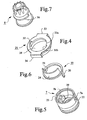
- a rotary-movement preventing member 19 is provided on the piston means 7.
- This member 19 is annular and includes two axially provided hook portions 20, 21 which can be inserted into grooves 22, 23 in the piston means 7 and hooked onto two shoulders 7a, 7b thereon in a radial direction. By means of this positioning, the rotary-movement preventing member 19 is attached to the piston means 7 and can not rotate relative to said means.
- the rotary-movement preventing member 19 further includes an axially provided flange 24 which is adapted to cooperate with a bracket 25 in order to prevent rotation of the rotary--movement preventing member 19 and thus, the piston means 7, relative to the bracket 25 such that the mixing means 9 is rotated relative to the piston means 7 for mixing of the powder and liquid components 5, 6.
- the bracket 25 has a cylindrical member 27 with a hole 28 into which the rotatable means 8 can be inserted and through which said rotatable means can move when it is set in a release position P2.
- the cylindrical member 27 of the bracket 25 may have an annular snap-in portion 29 which can be threaded into one or more locking portions 30 which are located at the inner side of the mixing container 3 and which allow the bracket 25 to be attached to the mixing container 3 by a snap-in closure.
- the bracket 25 may have a number of radially projecting members 33, 34 which can be attached to a radially outwards directed flange 35 on the mixing container 3 by a snap-in closure such that the bracket 25 can not rotate relative to said container.
- the rotatable means 8 has a through hole 8a through which the elongated member 10 of the mixing means 9 extends such that said elongated member 10 is movable relative to the rotatable means 8 and vice versa.
- the rotatable means 8 has a first flange 36 or a corresponding member which in relation to the direction U extends radially outwards from the rotatable means 8 towards a discharge opening 49 through which the mass 2 shall pass out of the mixing container 3.
- Said first flange 36 surrounds a part of the periphery of the rotatable means 8.
- the hole 28 of the bracket 25 has a second flange 31 a or a corresponding second member which relative to the direction U is directed radially into the hole 28.
- This second flange 31 a extends along a part of the periphery of the hole 28.
- a section 31 b or a corresponding third part of the hole 28 lacks said flange 31 a and is designed such that the first flange 36 of the rotatable means 8 can pass therethrough, whereby the entire rotatable means 8 can be brought to pass through the hole 28 when the first flange 36 and the section 31 b cooperate.
- the first and second flanges 36 and 31 a cooperate and prevent the rotatable means 8 from moving relative to the bracket 25 in direction U, while the mixing means 9 can move and be brought to perform mixing movements for mixing the powder and liquid components in the mixing space 4.
- the rotatable means 8 can be brought to its release position P2 ( fig. 2 ) by rotating it 180° relative to the bracket 25 from its retaining position P1 and this rotary movement can be limited by bringing the first flange 36 thereof to engage or abut a rotary stop 32. Thereby, the first flange 36 of the rotary means 8 will be disengaged from the cooperation with the second flange 31 a of the bracket 25 and it can instead cooperate with the section 31 b of the bracket 25 such that the rotatable means 8 and thus, the piston means 7, can move and be displaced in direction U in relation thereto and thus, relative to the mixing container 3.
- the piston means 7 is prevented from rotating relative to the bracket 25 by the flange 24 of the rotary-movement preventing member 19 engaging or gripping preferably into the section 31 b of the bracket 25 when the rotatable means 8 retains the piston means 7 at the bracket 25.
- the rotatable means 8 cooperates preferably with a coupling device 37 which is provided to interconnect the piston means 7 and the elongated member 10 of the mixing means 9 such that the piston means 7 (and the rotatable means 8 provided thereby) can be displaced in axial direction U relative to the mixing container 3 by means of the mixing means 9 for discharge of mixed mass 2 from the mixing space 4.
- the coupling device 37 is located between the rotatable means 8 and the piston means 7 and it is preferably provided to be operated by the rotatable means 8 such that it connects the piston means 7 to the elongated member 10 while simultaneously the rotatable means 8 is rotated from its retaining position P1 to its release position P2.
- the coupling device 37 may comprise a coupling means 38, e.g. a washer, which is threaded onto the elongated member 10 and which is located between the piston means 7 and the rotatable means 8.
- the piston means 7 has a support member 39 which is axially directed towards the rotatable means 8 and located on one side of the elongated member 10, while there is a free space 40 on the other side of the elongated member 10.
- the rotatable means 8 has an axially directed bore 41, the rear parts of which are provided with a helical spring 42 or a similar resilient element and the fore parts with a pin 43 which projects out of the bore 41.
- the bore 41 with the helical spring 42 is located on the same side of the elongated member 10 and the helical spring thereby presses the coupling means 38 against the support member 39 such that said coupling means 38 is held in a neutral position P3 in which it is held against the support member 39 and permits displacement of the elongated member 10 of the mixing means 9 in opposite axial mixing directions B, whereby the powder and liquid components 5, 6 can be mixed in the mixing space 4 with the mixing means 9 while the piston means 7 is retained relative to the mixing container 3.
- the bore 41 and the helical spring 42 will also move 180° relative to the support member 39 and the helical spring 42 will thereby press or push the coupling means 38 into the space 40, which means that the coupling means 38 is tilted relative to the elongated member 10 and is brought to a coupling position P4 in which the coupling means 38 is fastened to the elongated member 10.
- the piston means 7 is connected to the mixing means 9 such that the piston means 7 can be displaced in the direction U by said mixing means 9.
- the coupling device 37 is designed such that it, after said interconnection of the mixing means 9 and the piston means 7, permits release of the mixing means 9 relative to the piston means 7 if said mixing means 9 is pulled in the return direction R relative to the piston means 7.
- an outer member 45 with an open end portion 45a and such a cavity or depression 45b within the end portion 45a that said end portion will engage or abut the mixing container 3 when the mixing means 9 is displaced in axial direction towards the mixing container 3 and rotated relative to said container during mixing.
- an outer member 45 with an open end portion 45a and such a cavity or depression 45b within the end portion 45a that said end portion will engage or abut the mixing container 3 when the mixing means 9 is displaced in axial direction towards the mixing container 3 and rotated relative to said container during mixing.
- the bracket 25 is preferably provided to prevent the piston means 7 and the mixing means 9 from being pulled apart from the mixing container 3.
- the rotatable means 8 can move together with the piston means 7 in the mixing space 4 of the mixing container 3, it is ensured that the device 1 will be simple and that it provides for a simple and quick handling when mixing of the powder and liquid components 5, 6 has been performed and the mixed mass 2 shall be discharged. To this end, it is only necessary to rotate the rotatable means 8 from its retaining position P1 to the release position P2, whereafter it is possible to displace the piston means 7 by means of the mixing means 9 in the direction U for discharge of the mass 2 from the mixing space 4.
- At least one opening 47 can be provided in the side of the mixing container 3 adjacent the piston means 7 when said piston means is retained by the bracket 25. Since the opening 47 is located adjacent the piston means 7, it is closed when the piston means 7 starts to move in the direction U and after further movement of the piston means 7, it will be located behind said piston means, which means that only gas and no mass 2 can be pressed out through the opening 47.
- openings there may be at least one opening 48 in the side of the mixing container 3 about half the way between the piston means 7, when retained by the bracket 25, and a discharge opening 49 which is provided in the mixing container 3 for discharge of the mass 2 from said container.
- the opening 48 may be closable when necessary.
- opening 17 or openings 47 or 48 permit gas to be pressed out of the mixing space 4 when e.g. the liquid component 6 is injected into said space. Since gas hereby can be pressed out, injection of the liquid component 6 is facilitated. Due to its location, the opening 48 permits gas which is entrapped in the mass 2 to be pressed out of or escape from said mass during discharge thereof.
- At least one vacuum generating device can be provided to generate a vacuum in the mixing space 4 for various purposes, preferably for facilitating quick suction of the liquid component 6 to and distribution thereof in the powder component 5 and/or e.g. for sucking out toxic gases therefrom, which are generated during mixing of the powder and liquid components 5, 6.
- a vacuum in the mixing space 4 for various purposes, preferably for facilitating quick suction of the liquid component 6 to and distribution thereof in the powder component 5 and/or e.g. for sucking out toxic gases therefrom, which are generated during mixing of the powder and liquid components 5, 6.
- first vacuum generating device 50 which at a suitable location can be connected to the mixing container 3.
- a first vacuum generating device 50 is schematically illustrated in fig. 1 .
- the mixing means 9 can be subjected to linear forces such that said mixing means 9 and the piston means 7 are displaced linearly relative to the mixing container 3.
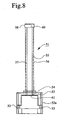
- the mixing means 9 can be displaced linearly by influence from a screw device 51.
- the screw device 51 e.g. includes a nut-like member 52 which has a laterally open fork--like member 52a with laterally open grooves 53 permitting sideways threading of the nut--like member 52 onto the flange 35 of the mixing container 3 such that said member 52 is stuck on the mixing container 3.
- the nut-like member 52 is provided with a tapped hole 54 for a screw-like member 55 with outer threads 56 which mesh with the threads in the tapped hole 54 of the nut-like member 52.
- the screw-like member 55 may be a pipe member with a multi-side nut 58 and the pipe member may have a longitudinal slit 57 which is open in a lateral direction and the nut may have an open side 60 such that the screw-like member 55 and the nut 58 can be threaded onto the elongated member 10 of the mixing means 9.
- the nut 58 is adapted to fit into a corresponding multi-side hole 59 in the outer member 45 or any other member on or of the operating handle 13.
- said device can be non--rotatably located on the mixing container 3 and since the nut 58 can be inserted into the hole 59, the screw-like member 55 may, by means of the operating handle 13, be screwed into the nut-like member 52 via e.g. the outer member 45, whereby the end portion 61 of the screw-like member 55 is brought in contact with the rotatable means 8 and can impart discharge forces in the direction U to the rotatable means 8 and through said rotatable means to the piston means 7.
- the piston means 7 can be moved in the direction U either by manually pressing the operating handle 13 or rotating it and transfer the rotary movement by means of the screw device 51. If great forces are required for discharging the mass 2 from the mixing space 4, one can use a gun-like discharge device 62 or a similar device as is schematically indicated in fig. 1 .
- the mixing container 3 is positioned therein such that a pressure means 63 can cooperate with the mixing means 9 or directly with the piston means 7 if there is no mixing means.
- the pressure means 63 is operated by a manually depressable trigger which can move the pressure means 63 stepwise such that said pressure means with force press the mixing means 9 and/or the piston means 7 forward in the direction U.
- the mixing space 4 of the mixing container 3 may carry the powder component 5 when the device 1 is delivered.
- the discharge opening 49 is hereby closed by a closing device 64 which prevents the powder component 5 from falling out of the mixing space 4.
- the liquid component 6 can be provided in a liquid container 65 and can be fed into the mixing space 4 for mixing therein with the powder component 5.
- the liquid container 65 has a discharge end 66 and the closing device 64 can be designed such that the discharge end 66 can open the closing device 64 when it is inserted into said device for injecting the liquid component 6 into the mixing space 4 and the powder component 5 therein.
- the closing device 64 may comprise a valve body 64a which is normally closed and which is opened by the discharge end 66 when said end is inserted into the closing device 64 and automatically returned to closed position when the discharge end 66 is removed or withdrawn from the closing device 64.
- a valve 67 can be provided to cooperate with the closing device 64 to permit gas to escape from the mixing space 4 when the liquid component 6 is injected into said space from the liquid container 65. This valve 67 can be closed and may be opened when required.
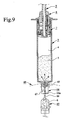
- the mixing container 3 or parts thereof may be brought in contact with a vibrating device 68 schematically illustrated in fig. 9 .
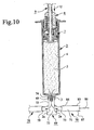
- the mixing container 3 can be connected to a distributor device 69 or vice versa.
- Several containers 70 can be connected thereto or vice versa, such that mass 2 mixed in the mixing space 4 can be fed out or discharged from said mixing space and into the distributor device 69.
- the distributor device 69 distributes the mass 2 to the various containers 70 such that portions of the mass 2 are fed into inner spaces 71 in the containers 70.
- the inner space 71 in each container 70 is substantially smaller than the mixing space 4 of the mixing container 3, which means that one can fill the spaces 71 of a plurality of containers 70, e.g. the spaces 71 of eight containers 70, with a part volume 2a of the mass 2 from the mixing space 4.
- each container 70 can be removed from the distributor device 69 or vice versa and the part volume 2a of mass 2 in the container 70 can be fed and/or sucked out of the container 70.
- the distributor device 69 preferably comprises a distributor body 72 with an axial inlet pipe 73 which can be located close to such an outlet or discharge end 74 of the mixing container 3 having the discharge opening 49.
- the inlet pipe 73 can be located at the discharge end 74 by screwing on or in any other suitable manner such that inner passages in the distributor body 72 communicate with the discharge opening 49.
- the mixing container may instead be located on the inlet pipe 73.
- the distributor device 69 may also comprise a number of discharge pipes 75-82, at least two and e.g. eight pipes, which extend radially in a star-like manner from the distributor body 72 and which communicate with inner members of the distributor body 72.
- Each container 70 has a front part 84 through which it can be mounted, e.g. screwed on to one of the discharge pipes 75-82 of the distributor device 69 or vice versa, such that a part volume 2a of mass 2 can be fed into the space 71.
- a piston 86 forming part of the container 70 is preferably located in a rear part 85 of the container 70.
- a cannula or needle 83 can be located on the front part 84. The part volume 2a of mass 2 is fed or sucked out of the space 71 of the container 70 through said cannula 83.
- Each container 70 may eventually have an opening 87 which preferably is found in the rear part 85 and immediately in front of the piston 86 when said piston is situated in the rear part 85.
- This opening 87 allows gas in the space 71 of the container 70 to be pressed out of the space when said part volume 2a of mass 2 is fed into said space 71.
- the opening 87 has e.g. a diameter of 0,2-1,0 mm, preferably about 0,6 mm.
- the opening 87 may alternatively be a groove (not shown) provided axially in the inner side of the container 70 and extending beyond the piston 86 when said piston is situated in the rear part 85 of the container 70.
- one container 70 at the time is removed from the distributor device 69 and a cannula or needle 83 is mounted preferably on the front part 84 of the container 70 such that the part volume 2a of mass 2 can be fed or sucked out through the cannula 83 with or without support from the piston 86 until the space 71 is empty.
- a cannula or needle 83 is mounted preferably on the front part 84 of the container 70 such that the part volume 2a of mass 2 can be fed or sucked out through the cannula 83 with or without support from the piston 86 until the space 71 is empty.
- each container 70 Since the size of the space 71 in each container 70 is known, one knows exactly how large a part volume 2a of mass 2 which is fed out of or discharged from each container 70.
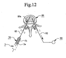
- a container 70 is connected to the spongy bone 89 by inserting the cannula 83 thereof, or a member (not shown) to which the cannula 83 can be connected, into the inner parts 89a such that the space 71 of the container 70 communicates therewith.
- Inner parts 89a of the spongy bone 89 can be provided with mass 2 from the mixing container 3.
- the mixing container 3 can be provided with a cannula or needle (not shown) or similar and this cannula is inserted into the inner parts 89a.
- the mass 2 can thereby be sucked out of the mixing space 4 of the mixing container 3 and into the inner parts 89a by means of the vacuum source 90.
- this suction of mass 2 from the mixing space 4 may be supported by a displacement of the piston means 7 in the direction U.
- the spongy bone 89 may e.g. be a spongy vertebra or an osteoporosis fracture in the form of a thighbone (femoral) or knee (patellar) fracture.
- Mixed mass 2 in the mixing container 3 can be used for fixation of implants, whereby one can provide the container with a discharge pipe or similar (not shown), through which the mass 2 is discharged by means of the piston means 7 into cavities in the bone in which the implant shall be fixed.
- the mass 2 may consist of bone substitute and/or bone reinforcing material which primarily consist of calcium base material or ceramics which can be mixed with a hardener, e.g. water. These substances may be selected from the group comprising calcium sulphate- ⁇ -hemihydrate, calcium sulphate- ⁇ -hemihydrate, calcium sulphate-dihydrate, calcium carbonate, ⁇ -tricalcium phosphate, hydroxyapatite, dicalcium phosphate-dihydrate, anhydrous dicalcium phosphate, tetracalcium phosphate, ⁇ -tricalcium phosphate, calcium deficient hydroxyapatite, monocalcium phosphate-monohydrate, monocalcium phosphate, calcium-pyurophosphate, precipitated hydroxyapatite, carbonaceous apatite (dahlite), octacalcium phosphate, amorphous calcium phosphate, oxyapatite, carbonato apatite and calcium aluminate
- a ceramic material may be calcium aluminate, which forms part of the product Doxa T from the company Doxa (www.doxa.se/pdf/nyhet_1.pdf).
- X-ray contrast agents can be added to said ceramic bone substitute and/or bone reinforcing material, e.g. water soluble non-ionic X-ray contrast agents selected from the group comprising iohexol, ioversol, iopamidol, iotrolan, metrizamide, iodecimol, ioglucol, ioglucamide, ioglunide, iogulamide, iomeprol, iopentol, iopromide, iosarcol, iosimide, iotusal, ioxilan, iofrotal and iodecol.
- water soluble non-ionic X-ray contrast agents selected from the group comprising iohexol, ioversol, iopamidol, iotrolan, metrizamide, iodecimol, ioglucol, ioglucamide, ioglunide, iogulamide,
- the mass 2 can be a hardenable bone cement comprising polymer and monomer components.
- the polymer may be polymethylmethacrylate (PMMA) and the monomer methylmethacrylate (MMA).
- a polymer base material can be the product Cortoss TM from the company Orthovita in the U.S.A.. For composition see www.orthovita.com/products/cortoss/oustechspecs.html.
- Another polymer base material can be the product SECOUR® Acrylic Resin PMMA from parallax medical inc. (www.parallax-medical.com/go/91-92b550-5642 - 1157-a432-d7a2b98310fe).
- the mass 2 can be a bone substitute and/or bone reinforcing material and consist of a mineral and/or a ceramic in combination with polymer material.
- the mass 2 may be another type of mass than bone substitute and/or bone reinforcing material or bone cement or similar.
- the rotatable means 8 may cooperate with the piston means with other means than those shown and described; mixing may be carried through in another way than with a mixing means 9 and if there is such a means, this may be designed otherwise; the mixing container 3 may be designed in another way than what is described and illustrated; when using a screw device 51, this may be of another type than the one described and illustrated and this also refers to the distributor device 69.
- the piston means 7 may either be moved in the direction U by the mixing means 9 or be sucked in the same direction by the vacuum source 90, but it is also possible to move the piston means 7 by using the mixing means 9 and the vacuum source 90 simultaneously.
- the device 1 may be of the disposable type or used repeatedly.
Landscapes
- Health & Medical Sciences (AREA)
- Orthopedic Medicine & Surgery (AREA)
- Life Sciences & Earth Sciences (AREA)
- Surgery (AREA)
- Engineering & Computer Science (AREA)
- Chemical & Material Sciences (AREA)
- Chemical Kinetics & Catalysis (AREA)
- Public Health (AREA)
- Biomedical Technology (AREA)
- Heart & Thoracic Surgery (AREA)
- Veterinary Medicine (AREA)
- Animal Behavior & Ethology (AREA)
- General Health & Medical Sciences (AREA)
- Medical Informatics (AREA)
- Molecular Biology (AREA)
- Nuclear Medicine, Radiotherapy & Molecular Imaging (AREA)
- Mechanical Engineering (AREA)
- Transplantation (AREA)
- Physics & Mathematics (AREA)
- Fluid Mechanics (AREA)
- Vascular Medicine (AREA)
- Anesthesiology (AREA)
- Physical Education & Sports Medicine (AREA)
- Hematology (AREA)
- Cardiology (AREA)
- Oral & Maxillofacial Surgery (AREA)
- Prostheses (AREA)
- Developing Agents For Electrophotography (AREA)
- Diaphragms For Electromechanical Transducers (AREA)
- Mixers Of The Rotary Stirring Type (AREA)
- Discharge Heating (AREA)
- Processes Of Treating Macromolecular Substances (AREA)
- Control Of Motors That Do Not Use Commutators (AREA)
- External Artificial Organs (AREA)
- Insulated Conductors (AREA)
- Materials For Medical Uses (AREA)
- Accessories For Mixers (AREA)
- Curing Cements, Concrete, And Artificial Stone (AREA)
- Macromonomer-Based Addition Polymer (AREA)
- Infusion, Injection, And Reservoir Apparatuses (AREA)
Claims (48)
- Vorrichtung zur Herstellung einer härtbaren Masse, vorzugsweise eines Knochenersatzstoffes und/oder Knochenverstärkungsmaterials oder Knochenzements oder eines ähnlichen Materials,
wobei ein Mischbehälter (3) einen Mischraum (4) aufweist, in welchem mindestens ein Pulver und mindestens ein flüssiger Bestandteil (5, 6) zur Erzeugung der härtbaren Masse (2) vermischt werden,
wobei im Mischraum (4) des Mischbehälters (3) ein Kolbenorgan (7) vorgesehen ist, und
wobei mindestens ein relativ zum Mischbehälter (3) rotierbares Organ (8) mit dem Kolbenorgan (7) zusammenwirkt, um, in einer Halteposition (P1), das Kolbenorgan (7) relativ zum Mischbehälter (3) festzuhalten, und, durch Rotation in eine Freigabeposition (P2), das Kolbenorgan (7) derart freizugeben, dass sich das Kolbenorgan in eine Richtung (U) auf mindestens eine Öffnung (49) zubewegen kann, durch welche hindurch die Masse (2) aus dem Mischraum (4) austreten kann,
dadurch gekennzeichnet,
dass das rotierbare Organ (8) derart angeordnet ist, dass es in seiner Freigabeposition (P2) dem Kolbenorgan (7) im Mischraum (4) in Richtung (U) zu der Öffnung (49) folgen kann. - Vorrichtung nach Anspruch 1, dadurch gekennzeichnet,
dass das rotierbare Organ (8) ein erstes Element (36) umfasst, welches zum Zusammenwirken mit einem zweiten und einem dritten Element (31 a, 31 b) gebracht werden kann, welche relativ zum Mischbehälter (3) derart unbeweglich vorgesehen sind, dass das erste Element (36) des rotierbaren Organs (8) mit dem zweiten Element (31a) des Mischbehälters (3) zusammenwirkt, wenn sich das rotierbare Organ (8) in seiner Halteposition (P1) befindet, um zu verhindern, dass sich das rotierbare Organ (8) und das Kolbenorgan (7) in Richtung (U) auf die die Öffnung (49) zubewegen, und
dass das erste Element (36) des rotierbaren Organs (8) durch Rotieren des rotierbaren Organs (8) in seine Freigabeposition (P2) aus dem Zusammenwirken mit dem zweiten Element (31a) und ins Zusammenwirken mit dem dritten Element (31 b) rotieren kann, um zu ermöglichen, dass sich das rotierbare Organ (8) und das Kolbenorgan (7) in Richtung (U) gegen die Öffnung (49) bewegen können. - Vorrichtung nach Anspruch 2, dadurch gekennzeichnet,
dass das erste Element des rotierbaren Organs (8) einen ersten Flansch (36) darstellt, welcher relativ zur Richtung (U) vom rotierbaren Organ (8) radial nach außen gerichtet ist und sich um einen Teil des Umfangs des rotierbaren Organs (8) herum erstreckt,
dass das zweite Element einen zweiten Flansch (31a) darstellt, welcher relativ zur Richtung (U) radial in ein Loch (28) gerichtet ist, durch welches Loch das rotierbare Organ (8) zu gelangen ausgebildet ist, wenn sich das rotierbare Organ in seiner Freigabeposition (P2) befindet, und welcher sich entlang eines Teils des Umfangs des Lochs (28) erstreckt, und
dass das dritte Element einen solchen Abschnitt (31 b) des Umfangs des Lochs (28) darstellt, an welchem der zweite Flansch (31 a) fehlt, und durch welchen Abschnitt (31 b) hindurch der erste Flansch (36) des rotierbaren Organs (8) passieren kann. - Vorrichtung nach Anspruch 2 oder 3, dadurch gekennzeichnet, dass das zweite und dritte Element (31 a, 31 b) an einem an dem Mischbehälter (3) anordenbaren Halter (25) angeordnet sind.
- Vorrichtung nach Anspruch 4, dadurch gekennzeichnet, dass der Halter (25) durch einen Schnappverschluss auf den Mischbehälter (3) aufsteckbar ist.
- Vorrichtung nach Anspruch 4 oder 5, dadurch gekennzeichnet, dass ein eine Rotationsbewegung verhinderndes Element (19) vorgesehen ist, um eine Rotation des Kolbenorgans (7) relativ zum Halter (25) zu verhindern, wenn das rotierbare Organ (8) relativ zum Kolbenorgan (7) rotiert.
- Vorrichtung nach Anspruch 6, dadurch gekennzeichnet,
dass das eine Rotationsbewegung verhindernde Element (19) an dem Kolbenorgan (7) angeordnet ist, und
dass das eine Rotationsbewegung verhindernde Element (19) dazu vorgesehen ist, mit dem Halter (25) derart zusammenzuwirken, dass der Halter eine Rotation des eine Rotationsbewegung verhindernden Elements (19) und damit des Kolbenorgans (7) relativ zum Halter (25) verhindert, wenn das rotierbare Organ relativ zum Kolbenorgan (7) rotiert wird. - Vorrichtung nach einem der vorgehenden Ansprüche, dadurch gekennzeichnet, dass zum Begrenzen der Rotationsbewegung des rotierbaren Organs (8) ein drehbarer Anschlag (32) vorgesehen ist.
- Vorrichtung nach einem der vorgehenden Ansprüche, dadurch gekennzeichnet, dass das rotierbare Organ (8) eine Durchbrechung (8a) für ein längliches Element (10) eines Mischorgans (9) aufweist, welches zum Vermischen des Pulvers und der flüssigen Bestandteile (5, 6) in dem Mischraum (4) vorgesehen ist.
- Vorrichtung nach Anspruch 9, dadurch gekennzeichnet,
dass das rotierbare Organ (8) mit einer Kupplungsvorrichtung (37) zusammenwirkt, welche zwischen dem rotierbaren Organ (8) und dem Kolbenorgan (7) zur gegenseitigen Verbindung des Kolbenorgans (7) und des länglichen Elements (10) des Mischorgans (9) angeordnet ist, und
dass das Kolbenorgan (7) nach Verbinden von diesem mit dem länglichen Element (10) des Mischorgans (9) mittels des Mischorgans (9) zum Ausstoßen gemischter Masse (2) aus dem Mischraum (4) in einer Richtung (U) versetzbar ist. - Vorrichtung nach Anspruch 10, dadurch gekennzeichnet,
dass die Kupplungsvorrichtung (37) ein mit einem Stützelement (39) an dem Kolbenorgan (7) zusammenwirkendes Kupplungsorgan (38) umfasst, welches Stützelement (39) an einer Seite des länglichen Elements (10) des Mischorgans (9) angeordnet ist,
dass das rotierbare Organ (8) ein elastisches Element (42) umfasst, welches an derselben Seite des länglichen Elements (10) angeordnet ist, wenn das rotierbare Organ (8) sich in seiner Halteposition (P1) befindet, so dass das elastische Element (42), wenn das Kupplungsorgan (38) gegen das Stützelement (39) gehalten wird, das Kupplungsorgan (38) in seine neutrale Position (P3) bringt, und
dass das rotierbare Organ (8) durch eine Rotation von diesem in seine Freigabeposition (P2) das elastische Element (42) auf eine entgegengesetzte Seite des länglichen Elements (10) zubewegt und somit das Kupplungsorgan (38) in seine Kupplungsposition (P4) bringt, in welcher es zum länglichen Element (10) geklemmt oder befestigt wird. - Vorrichtung nach Anspruch 10 oder 11, dadurch gekennzeichnet, dass die Kupplungsvorrichtung (37) dazu vorgesehen ist, das Mischorgan (9) vom Kolbenorgan (7) zu lösen, wenn das Mischorgan (9) in eine zur Richtung (U) der Öffnung entgegengesetzte Richtung (R) relativ zum Kolbenorgan (7) gezogen wird.
- Vorrichtung nach einem der Ansprüche 9 bis 12, dadurch gekennzeichnet, dass das längliche Element (10) des Mischorgans (9) ein außerhalb des Mischbehälters (3) angeordnetes Außenelement (45) umfasst, welches dazu ausgebildet ist, mit diesem in Kontakt gebracht zu werden, um zu verhindern, dass es mit dem rotierbaren Organ (8) in Kontakt gelangt, um eine Rotation des rotierbaren Organs (8) durch das Mischorgan (9) zu vermeiden, wenn das Mischorgan (9) während Vermischen von Pulver und flüssigen Bestandteilen (5, 6) rotiert wird.
- Vorrichtung nach einem der vorgehenden Ansprüche, dadurch gekennzeichnet, dass zur Freigabe oder Ableitung von Gasen aus dem Mischraum (4) mindestens eine Öffnung (17, 47 oder 48) vorgesehen ist.
- Vorrichtung nach Anspruch 14, dadurch gekennzeichnet, dass die Öffnung (47) in dem Kolbenorgan (7) vorgesehen ist.
- Vorrichtung nach Anspruch 14, dadurch gekennzeichnet, dass die Öffnung (47) in einer Seite des Mischbehälters (3) angrenzend an dem Kolbenorgan (7) bei der Festhaltung des Kolbenorgans (7) durch den Halter (25) derart angeordnet ist, dass die Öffnung (47) bei der Bewegung des Kolbenorgans (7) in einer Richtung (U) durch dieses geschlossen wird.
- Vorrichtung nach einem der Ansprüche 14 bis 16, dadurch gekennzeichnet, dass die Öffnung (17) einen Filter (18) aufweist, welcher das Pulver und/oder den flüssigen Bestandteil (5 und/eller 6) und/oder die daraus vermischte Masse (2) daran hindert, durch die Öffnung (17) hinaus zu treten.
- Vorrichtung nach einem der vorgehenden Ansprüche, dadurch gekennzeichnet, dass mindestens eine Öffnung (48) in einer Seite des Mischbehälters (3), etwa am halben Wege zwischen dem Kolbenorgan (7), wenn das Kolbenorgan (7) durch das rotierbare Organ (8) festgehalten wird, und der Öffnung (49), durch welche die gemischte Masse (2) aus dem Mischbehälter (3) passieren kann, vorgesehen ist, und dass die erste Öffnung (48) schließbar ist.
- Vorrichtung nach einem der Ansprüche 1 bis 13, dadurch gekennzeichnet, dass eine ein Vakuum erzeugende Vorrichtung (50) vorgesehen ist, um ein Vakuums in dem Mischraum (4) zu erzeugen.
- Vorrichtung nach Anspruch 19, dadurch gekennzeichnet, dass die ein Vakuum erzeugende Vorrichtung (50) zur Erzeugung eines Vakuums in dem Mischraum (4) gebracht wird, um das Ansaugen des flüssigen Bestandteils (6) in den Mischraum (4) zu beschleunigen.
- Vorrichtung nach einem der vorgehenden Ansprüche, dadurch gekennzeichnet, dass eine Schneckenvorrichtung (51) zur Bereitstellung einer Ausstoßbewegung mittels Schneckenbewegungen gegen das Kolbenorgan (7) in eine Richtung (U) zum Ausstoßen von gemischter Masse (2) aus dem Mischraum (4) vorgesehen ist.
- Vorrichtung nach Anspruch 21, dadurch gekennzeichnet,
dass die Schneckenvorrichtung (51) ein nutartiges Element (52) umfasst, welches an dem Mischbehälter (3) derart angeordnet werden kann, dass die Schneckenvorrichtung (51) relativ zum Mischbehälter (3) nicht-rotierbar ist,
dass die Schneckenvorrichtung (51) ferner ein in das nutartige Element (52) eingeschraubtes, schneckenartiges Element (55) umfasst, welches an einem Bedienungsgriff (13) oder einem ähnlichen Formteil des Mischorgans (9) derart angeordnet werden kann, dass der Bedienungsgriff (13) und das schneckenartige Element (55) miteinander nicht-rotierbar verbunden sind, und
dass das schneckenartige Element (55) durch Einschrauben des schneckenartigen Elements (55) in das nutartige Element (52) mittels des Bedienungsgriffes (13) das Kolbenorgan (7) in eine Richtung (U) bewegen kann. - Vorrichtung nach Anspruch 22, dadurch gekennzeichnet, dass das schneckenartige Element (55) ein Rohrelement mit einer mehrseitigen Nut (58) darstellt, und das Rohrelement einen in einer seitlichen Richtung offenen, länglichen Schlitz (57) aufweist, und die Nut (58) eine offene Seite (60) aufweist, so dass das Rohrelement (55) und die Nut (58) auf ein längliches Element (10) des Mischorgans (9) aufgeschraubt werden können.
- Vorrichtung nach einem der vorhergehenden Ansprüche, dadurch gekennzeichnet, dass das Kolbenorgan (7) als Teil einer Schraube zum Ausstoßen von gemischter Masse (2) aus dem Mischraum (4) ausgebildet ist.
- Vorrichtung nach einem der vorhergehenden Ansprüche, dadurch gekennzeichnet, dass das Kolbenorgan (7) zur Betätigung in einer Richtung (U) zum Ausstoßen von gemischter Masse (2) aus dem Mischraum (4) vorgesehen ist, entwedera) durch Bewegen des Kolbenorgans (7) in eine Richtung (U) dadurch, dass ein Bedienungsgriff (13) oder dergleichen einer linearen Ausstoßkraft unterworfen wird, oderb) durch Bewegen des Kolbenorgans (7) in die Richtung (U) dadurch, dass der Bedienungsgriff (13) mit von einer Schneckenvorrichtung (51) auf das Kolbenorgan (7) übertragbaren Schneckenbewegungen beaufschlagt wird, oderc) durch Positionieren der Vorrichtung (1) in einer pistolenartigen Ausstoßvorrichtung (62), welche zur Erzeugung von auf das Kolbenorgan (7) übertragenen Ausstoßkräften stufenweise betätigt werden kann, um dieses in die Richtung (U) zu bewegen.
- Vorrichtung nach einem der vorgehenden Ansprüche, dadurch gekennzeichnet,
dass der Mischraum (4) des Mischbehälters (3) versiegelt ist und den Pulverbestandteil (5) enthält, und
dass der flüssige Bestandteil (6) in den Mischraum (4) gespeist werden kann, wenn das Vermischen des Pulvers und der flüssigen Bestandteile (5, 6) stattfinden soll. - Vorrichtung nach Anspruch 26, dadurch gekennzeichnet,
dass eine Ausstoßöffnung (49) zum Ausstoßen gemischter Masse (2) aus dem Mischraum (4) durch eine Schließvorrichtung (64) geschlossen ist,
dass der flüssige Bestandteil (6) in einem Flüssigkeitsbehälter (65) mit einem Ausstoßende (66) angeordnet ist, durch welches der flüssige Bestandteil (6) aus dem Flüssigkeitsbehälter (65) abgeleitet oder gespeist werden kann, und
dass die Schließvorrichtung (64) dazu vorgesehen ist, mittels des Ausstoßendes (66) des Flüssigkeitsbehälters (65) geöffnet zu werden, wenn das Ende (66) in die Schließvorrichtung (64) eingesetzt wird, so dass der flüssige Bestandteil (6) in den Mischraum (4) eingespeist werden kann, und dass die Schließvorrichtung (64) dazu vorgesehen ist, noch einmal zu schließen, wenn das Ausstoßende (66) des Flüssigkeitsbehälters (65) von der Schließvorrichtung (64) entfernt oder davon zurückgezogen wird. - Vorrichtung nach Anspruch 27, dadurch gekennzeichnet, dass ein Ventil (67) zum Zusammenwirken mit der Schließvorrichtung (64) vorgesehen ist, um zu ermöglichen, dass Gas aus dem Mischraum (4) entweichen oder austreten kann, wenn der flüssige Bestandteil (6) aus dem Flüssigkeitsbehälter (65) in diesen eingespeist wird.
- Vorrichtung nach einem der vorgehenden Ansprüche, dadurch gekennzeichnet, dass der Mischbehälter (3) dazu vorgesehen ist, mit einer Vibrationsvorrichtung (68) zusammemzuwirken, um das Pulver und die flüssigen Bestandteile (5, 6) und/oder die Masse (2) im Mischraum (4) zu vibrieren.
- Vorrichtung nach einem der vorgehenden Ansprüche, dadurch gekennzeichnet,
dass der Mischbehälter (3) mit einer Verteilervorrichtung (69) oder umgekehrt verbindbar ist,
dass eine Mehrzahl von Behältern (70) mit der Verteilervorrichtung (69) oder umgekehrt verbindbar sind,
dass im Mischraum (4) des Mischbehälters (3) gemischte Masse (2) in die Verteilervorrichtung (69) geleitet werden kann, welche zur Verteilung der Masse (2) in Räumen (71) in den Behältern (70) in einer solchen Weise vorgesehen ist, dass jeder Raum (71) in jedem Behälter (70) mit einem Teilvolumen (2a) der Masse (2) gefüllt wird, und
dass nach Entfernen der Behälter (70) aus der Verteilervorrichtung (69) jedes Teilvolumens (2a) der Masse (2) aus den Räumen (71) der Behälter (70) angesaugt und/oder gespeist werden kann. - Vorrichtung nach Anspruch 30, dadurch gekennzeichnet,
dass ein Vorderteil (84) jedes Behälters (70) mit der Verteilervorrichtung (69) oder umgekehrt derart verbindbar ist, dass ein Teilvolumen (2a) der Masse (2) in den Raum (71) des Behälters (70) gespeist werden kann, und
dass nach dem Bestücken des Raums (71) des Behälters (70) mit einem Teilvolumen (2a) von Masse (2) eine Kanüle oder Nadel am Vorderteil (84) oder umgekehrt angeordnet werden kann, durch welche Kanüle (83) das Teilvolumen (2a) von Masse (2) aus dem Raum (71) angesaugt und/oder gespeist werden kann. - Vorrichtung nach Anspruch 31, dadurch gekennzeichnet, dass während des Einspeisens eines Teilvolumens (2a) der Masse (2) in den Raum (71) des Behälters (70) ein Kolben (86) in jedem Behälter (70) in einem Hinterteil (85) des Behälters (70) eingestellt werden kann.
- Vorrichtung nach einem der Ansprüche 30 bis 32, dadurch gekennzeichnet, dass ein Hinterteil (85) des Behälters (70) eine Öffnung (87) aufweist, welche vor einem Kolben (86) angeordnet ist, wenn sich der Kolben in dem Hinterteil (85) befindet, und welche erlaubt, dass im Raum (71) des Behälters (70) befindliches Gas durch die Öffnung aus dem Raum (71) strömen kann, wenn der Raum (71) mit einem Teilvolumen (2a) von Masse (2) gefüllt ist.
- Vorrichtung nach einem der Ansprüche 30 bis 33, dadurch gekennzeichnet, dass ein Behälter (70) zur Zeit aus der Verteüervorrichtung (69) zu dessen Entleerung entfernt werden kann, während die übrigen Behälter (70) mit dieser verbunden bleiben.
- Vorrichtung nach einem der Ansprüche 1 bis 29, dadurch gekennzeichnet,
dass der Mischbehälter (3) zum Zusammenwirken mit inneren Teilen (89a) von Spongiosa (89) derart gebracht werden kann, dass sein Mischraum (4) mit den inneren Teilen (89a) in Verbindung steht, und
dass zur Erzeugung eines Vakuums in den Inneren Teilen (89a) des Knochenmaterials (89) zum Ansaugen gemischter Masse (2) aus dem Mischraum (4) in die inneren Teile (89a) mindestens eine Vakuumquelle (90) vorgesehen ist. - Vorrichtung nach Anspruch 35, dadurch gekennzeichnet, dass ein Kolbenorgan (7) zum Ausstoßen von Masse (2) aus dem Mischraum (4) bei einem gleichzeitigen Ansaugen von Masse (2) aus dem Raum (4) vorgesehen ist.
- Vorrichtung nach einem der Ansprüche 30 bis 34, dadurch gekennzeichnet,
dass der Behälter (70) mit dem Teilvolumen (2a) von Masse (2) zum Zusammenwirken mit inneren Teilen (89a) von Spongiosa (89) derart gebracht werden kann, dass der Raum (71) im Behälter (70) mit den inneren Teilen (89a) in Verbindung steht, und
dass zur Erzeugung eines Vakuums in den Inneren Teilen (89a) des Knochenmaterials (89) zum Ansaugen eines Teilvolumens (2a) von Masse (2) aus dem Raum (71) in die inneren Teile (89a) mindestens eine Vakuumquelle (90) vorgesehen ist. - Vorrichtung nach Anspruch 37, dadurch gekennzeichnet, dass zum Ausstoßen eines Teilvolumens (2a) von Masse (2) aus dem Raum (71) bei einem gleichzeitigen Ansaugen von Masse (2) aus dem Raum (71) ein Kolben (86) vorgesehen ist.
- Vorrichtung nach einem der Ansprüche 1 bis 30, dadurch gekennzeichnet, dass das Kolbenorgan (7) zum Ausstoßen härtbarer Masse (2) zum Fixieren von Knochenimplantaten vorgesehen ist.
- Vorrichtung nach einem der Ansprüche 1 bis 39, dadurch gekennzeichnet, dass die Masse (2) einen Knochenersatzstoff und/oder ein Knochenverstärkungsmaterial umfassend einen Bestandteil eines Calciumbasenmaterials oder im Wesentlichen eines Calciumbasenmaterials oder eines keramischen oder im Wesentlichen eines keramischen Materials darstellt.
- Vorrichtung nach Anspruch 40, dadurch gekennzeichnet, dass das Calciumbasenmaterial oder das keramische Material ein härtbares Mineral oder eine Keramik darstellt, welche(s) zum Aushärten in der Spongiosa (89) gebracht werden kann.
- Vorrichtung nach Anspruch 41, dadurch gekennzeichnet, dass das Calciumbasenmaterial oder die Keramik durch Vermischen mit einem Härtemittel wie Wasser zum Härten gebracht werden kann.
- Vorrichtung nach einem der Ansprüche 41 oder 42, dadurch gekennzeichnet, dass das Calciumbasenmaterial oder die Keramik aus der Gruppe umfassend Calciumsulfat-α-Hemihydrat, Calciumsulfat-β-Hemihydrat, Calciumsulfat-Dihydrat, Calciumcarbonat, α-Tricalciumphosphat, Hydroxyapatit, Dicalciumphosphat-Dihydrat, anhydrisches Dicalciumphosphat, Tetracalciumphosphat, β-Tricalciumphosphat, calciumarmes Hydroxyapatit, Monocalciumphosphat-Monohydrat, Monocalciumphosphat, Calciumpyurophosphat, gefälltes Hydroxyapatit, kohlenstoffhaltiges Apatit (Dahlit), Octacalciumphosphat, amorphes Calciumphosphat, Oxapatit, Carbonatapatit (Dahlit) und Calciumaluminat ausgewählt ist.
- Vorrichtung nach einem der Ansprüche 40 bis 43, dadurch gekennzeichnet, dass ein Röntgenkontrastmittel in das keramische Material vermischt ist.
- Vorrichtung nach Anspruch 44, dadurch gekennzeichnet, dass das Röntgenkontrastmittel wasserlöslich und nichtionisch ist.
- Vorrichtung nach Anspruch 45, dadurch gekennzeichnet, dass das wasserlösliche, nichtionische Röntgenkontrastmittel aus der Gruppe umfassend Iohexol, loversol, lopamidol, Iotrolan, Metrizamid, lodecimol, Ioglucol, Ioglucamid, loglunid, logulamid, Iomeprol, lopentol, lopromid, losarcol, losimid, lotusal, Ioxilan, lofrotal und lodecol ausgewählt ist.
- Vorrichtung nach einem der Ansprüche 1 bis 39, dadurch gekennzeichnet, dass die Masse (2) ein Knochenzement umfassend die Bestandteile Polymer, bevorzugt des Typs Polymethylmethacrylat (PMMA), und Monomer, bevorzugt des Typs Methylmethacrylat (MMA), darstellt, welche Bestandteile bei Vermischung miteinander aushärten.
- Vorrichtung nach einem der Ansprüche 40 bis 47, dadurch gekennzeichnet, dass der Knochenersatzstoff und/oder Knochenverstärkungsmaterial oder das Knochenzement aus einem Mineral und/oder einer Keramik in Kombination mit Polymermaterial besteht/bestehen.
Priority Applications (6)
| Application Number | Priority Date | Filing Date | Title |
|---|---|---|---|
| PL05752716T PL1758526T3 (pl) | 2004-06-22 | 2005-06-17 | Urządzenie do wytwarzania utwardzalnej masy |
| PL08151034T PL1920738T3 (pl) | 2004-06-22 | 2005-06-17 | Urządzenie do rozprowadzania masy utwardzalnej |
| EP08151033A EP1913888B1 (de) | 2004-06-22 | 2005-06-17 | Vorrichtung zur Herstellung einer härtbaren Masse |
| EP09158716.2A EP2108324B1 (de) | 2004-06-22 | 2005-06-17 | Vorrichtung zur Herstellung einer härtbaren Masse |
| PL08151033T PL1913888T3 (pl) | 2004-06-22 | 2005-06-17 | Urządzenie do wytwarzania masy utwardzalnej |
| EP08151034A EP1920738B1 (de) | 2004-06-22 | 2005-06-17 | Vorrichtung zur Verteilung einer härtbaren Masse |
Applications Claiming Priority (2)
| Application Number | Priority Date | Filing Date | Title |
|---|---|---|---|
| SE0401604A SE527528C2 (sv) | 2004-06-22 | 2004-06-22 | Anordning för framställning av härdbar massa samt användning av anordningen |
| PCT/SE2005/000932 WO2005122971A1 (en) | 2004-06-22 | 2005-06-17 | Device for producing a hardenable mass |
Related Child Applications (6)
| Application Number | Title | Priority Date | Filing Date |
|---|---|---|---|
| EP08151033A Division EP1913888B1 (de) | 2004-06-22 | 2005-06-17 | Vorrichtung zur Herstellung einer härtbaren Masse |
| EP09158716.2A Division EP2108324B1 (de) | 2004-06-22 | 2005-06-17 | Vorrichtung zur Herstellung einer härtbaren Masse |
| EP08151034A Division EP1920738B1 (de) | 2004-06-22 | 2005-06-17 | Vorrichtung zur Verteilung einer härtbaren Masse |
| EP08151033.1 Division-Into | 2008-02-04 | ||
| EP08151034.9 Division-Into | 2008-02-04 | ||
| EP09158716.2 Division-Into | 2009-04-24 |
Publications (2)
| Publication Number | Publication Date |
|---|---|
| EP1758526A1 EP1758526A1 (de) | 2007-03-07 |
| EP1758526B1 true EP1758526B1 (de) | 2010-03-03 |
Family
ID=32906836
Family Applications (4)
| Application Number | Title | Priority Date | Filing Date |
|---|---|---|---|
| EP05752716A Expired - Lifetime EP1758526B1 (de) | 2004-06-22 | 2005-06-17 | Vorrichtung zur herstellung einer härtbaren masse |
| EP09158716.2A Expired - Lifetime EP2108324B1 (de) | 2004-06-22 | 2005-06-17 | Vorrichtung zur Herstellung einer härtbaren Masse |
| EP08151033A Expired - Lifetime EP1913888B1 (de) | 2004-06-22 | 2005-06-17 | Vorrichtung zur Herstellung einer härtbaren Masse |
| EP08151034A Expired - Lifetime EP1920738B1 (de) | 2004-06-22 | 2005-06-17 | Vorrichtung zur Verteilung einer härtbaren Masse |
Family Applications After (3)
| Application Number | Title | Priority Date | Filing Date |
|---|---|---|---|
| EP09158716.2A Expired - Lifetime EP2108324B1 (de) | 2004-06-22 | 2005-06-17 | Vorrichtung zur Herstellung einer härtbaren Masse |
| EP08151033A Expired - Lifetime EP1913888B1 (de) | 2004-06-22 | 2005-06-17 | Vorrichtung zur Herstellung einer härtbaren Masse |
| EP08151034A Expired - Lifetime EP1920738B1 (de) | 2004-06-22 | 2005-06-17 | Vorrichtung zur Verteilung einer härtbaren Masse |
Country Status (15)
| Country | Link |
|---|---|
| US (4) | US7938572B2 (de) |
| EP (4) | EP1758526B1 (de) |
| JP (1) | JP4891900B2 (de) |
| KR (1) | KR101247172B1 (de) |
| CN (2) | CN102120156A (de) |
| AT (3) | ATE459311T1 (de) |
| AU (1) | AU2005253916B2 (de) |
| CA (2) | CA2569702C (de) |
| DE (3) | DE602005020073D1 (de) |
| ES (3) | ES2341504T3 (de) |
| PL (3) | PL1913888T3 (de) |
| PT (1) | PT1913888E (de) |
| SE (1) | SE527528C2 (de) |
| WO (1) | WO2005122971A1 (de) |
| ZA (1) | ZA200610100B (de) |
Families Citing this family (67)
| Publication number | Priority date | Publication date | Assignee | Title |
|---|---|---|---|---|
| SE520688C2 (sv) * | 2000-04-11 | 2003-08-12 | Bone Support Ab | Ett injicerbart ersättningsmaterial för benmineral |
| SE517168C2 (sv) * | 2000-07-17 | 2002-04-23 | Bone Support Ab | En komposition för ett injicerbart ersättningsmaterial för benmineral |
| SE522098C2 (sv) | 2001-12-20 | 2004-01-13 | Bone Support Ab | Ett nytt benmineralsubstitut |
| SE0300620D0 (sv) * | 2003-03-05 | 2003-03-05 | Bone Support Ab | A new bone substitute composition |
| SE0302983D0 (sv) * | 2003-11-11 | 2003-11-11 | Bone Support Ab | Anordning för att förse spongiöst ben med benersättnings- och/eller benförstärkningsmaterial och förfarande i samband därmed |
| US20070211563A1 (en) * | 2003-12-01 | 2007-09-13 | Broockeville Corporation N.V. | Two-Component Mixing and Dispensing Device |
| SE527528C2 (sv) | 2004-06-22 | 2006-04-04 | Bone Support Ab | Anordning för framställning av härdbar massa samt användning av anordningen |
| US8057090B1 (en) * | 2005-08-31 | 2011-11-15 | Subrata Saha | Automated bone cement mixer |
| DE602007008528D1 (de) * | 2006-02-10 | 2010-09-30 | Barger Mark A | Vorrichtung und Verfahren aufweisend ein einziehbares Mischelement |
| DE102007026034B4 (de) | 2007-06-04 | 2016-03-03 | Aap Biomaterials Gmbh | Verfahren zum Mischen von Mischgut mit einer Misch- und Applikationsvorrichtung |
| ITPD20070266A1 (it) * | 2007-08-02 | 2009-02-03 | Michela Facco | Dispositivo di distribuzione applicabile a dosatori manuali per vertebroplastica |
| DE102007061696B4 (de) | 2007-12-19 | 2010-03-18 | Heraeus Medical Gmbh | Mischvorrichtung, insb. für Knochenzemente |
| US8556495B2 (en) * | 2008-09-29 | 2013-10-15 | Lidds Ab | Injector device |
| US8162875B2 (en) * | 2008-09-30 | 2012-04-24 | Tyco Healthcare Group Ip | Diluent/medication mixing syringe assembly |
| US9643139B2 (en) | 2009-02-06 | 2017-05-09 | Tecres S.P.A. | Supply unit for a mixer of two-phase compounds |
| DE102009013211B4 (de) | 2009-03-17 | 2012-04-19 | Aap Biomaterials Gmbh | Vakuum-Mischvorrichtung für Knochenzement sowie Verfahren zum Mischen von Knochenzement |
| CH700895A1 (de) * | 2009-04-28 | 2010-10-29 | Medmix Systems Ag | Austragvorrichtung mit mischeinrichtung. |
| DE102009031178B3 (de) | 2009-06-29 | 2010-09-16 | Heraeus Medical Gmbh | Vorrichtung zum Mischen und Austragen von Knochenzement |
| US9180137B2 (en) | 2010-02-09 | 2015-11-10 | Bone Support Ab | Preparation of bone cement compositions |
| EP2353619A1 (de) | 2010-02-09 | 2011-08-10 | Bone Support AB | Herstellung von Knochenzementzusammensetzungen |
| DE102010052323A1 (de) * | 2010-11-25 | 2012-05-31 | Heraeus Medical Gmbh | Kartusche mit arretierbarem Förderkolben |
| DE102011005568A1 (de) * | 2011-03-15 | 2012-09-20 | Krones Aktiengesellschaft | Anlage und Verfahren zum Recyceln von Kunststoffen, bevorzugt PET |
| CH705193A1 (de) * | 2011-06-22 | 2012-12-31 | Medmix Systems Ag | Vorrichtung zum blasenarmen Mischen und Austragen eines Produkts. |
| DE102011112516B4 (de) | 2011-09-07 | 2024-02-29 | Stryker European Operations Holdings Llc | Gebinde mit einem Behälter zur Aufnahme einer Flüssigkeit und einer Flüssigkeitsentnahmeeinrichtung |
| DE102011119377B3 (de) | 2011-11-25 | 2013-04-04 | Heraeus Medical Gmbh | Lager- und Mischvorrichtung für Knochenzement |
| DE102011119371B3 (de) | 2011-11-25 | 2013-04-04 | Heraeus Medical Gmbh | Vorrichtung zum Mischen von Knochenzement |
| US9630355B2 (en) | 2011-11-30 | 2017-04-25 | King Abdulaziz City For Science And Technology | Batch mixer with plunger |
| US8833606B2 (en) * | 2012-01-03 | 2014-09-16 | Howmedica Osteonics Corporation | Device and method for mixing and applying biomaterials |
| JP6241624B2 (ja) | 2012-03-06 | 2017-12-06 | フェロサン メディカル デバイシーズ エイ/エス | 止血ペーストを収容する加圧容器 |
| CN104349797B (zh) | 2012-06-12 | 2017-10-27 | 弗罗桑医疗设备公司 | 干止血组合物 |
| KR101275638B1 (ko) * | 2012-10-31 | 2013-06-17 | (주)비엠코리아 | 골시멘트 혼합 주입 기구 |
| DE102012021623B4 (de) | 2012-11-06 | 2021-03-04 | Otto-Von-Guericke-Universität Magdeburg | Vorrichtung und Verfahren zur Kalibrierung von Trackingsystemen in Bildgebungssystemen |
| DE102012024710A1 (de) | 2012-11-07 | 2014-05-08 | Heraeus Medical Gmbh | Vorrichtung zum Mischen und Austragen einer pastösen Masse |
| DK2958603T3 (en) | 2013-02-20 | 2018-07-16 | Bone Support Ab | IMPROVED CURE FOR HARDWARE BONE COMPENSATION |
| US9604184B2 (en) | 2013-03-06 | 2017-03-28 | Orthovita, Inc. | Mixing system and valve assembly |
| EP2974752A4 (de) * | 2013-03-13 | 2016-10-19 | Nat Inst For Materials Science | Klebender knochenfüllstoff und kit mit dem klebenden knochenfüllstoff |
| DE102013011295A1 (de) * | 2013-07-08 | 2015-01-08 | Heraeus Medical Gmbh | Vorrichtung zum Lagern und Mischen von Knochenzement |
| DE202013010100U1 (de) | 2013-11-07 | 2015-02-09 | Mathys Ag Bettlach | Dosiervorrichtung zum Befüllen von Appliziervorrichtungen mit Knochenzement oder Knochenersatzpasten |
| EP3079731B1 (de) | 2013-12-11 | 2018-08-08 | Ferrosan Medical Devices A/S | Trockenzusammensetzung mit extrusionsverstärker |
| TWI651103B (zh) | 2013-12-13 | 2019-02-21 | 萊特醫技股份有限公司 | 多相骨移植替代材料 |
| DE102013226118B3 (de) * | 2013-12-16 | 2015-06-11 | Heraeus Medical Gmbh | Vorrichtung zum Lagern und Mischen von Knochenzement |
| JP6726852B2 (ja) | 2014-10-13 | 2020-07-22 | フェッローサン メディカル ディバイス エー/エス | 止血および創傷治癒に使用するための乾燥組成物 |
| DE202014008486U1 (de) | 2014-10-27 | 2016-01-28 | Mathys Ag Bettlach | Vorrichtung zum Applizieren von Knochenersatzpasten |
| EP3274003B1 (de) | 2015-03-23 | 2019-07-17 | Bone Support AB | Zweiphasiger keramischer knochenersatz |
| DE102015108783B3 (de) * | 2015-06-03 | 2016-07-14 | Heraeus Medical Gmbh | Vorrichtung zum Mischen und Lagern von Polymethylmethacrylat-Knochenzement |
| US10507293B2 (en) | 2015-06-24 | 2019-12-17 | Ethicon, Inc. | Hemostatic powder delivery devices and methods |
| AU2016290433B2 (en) * | 2015-07-03 | 2018-05-24 | Ferrosan Medical Devices A/S | Syringe for mixing two components and for retaining a vacuum in a storage condition |
| DE102015116797B4 (de) * | 2015-10-02 | 2018-08-23 | Heraeus Medical Gmbh | Vorrichtung und Verfahren zum Lagern und Mischen eines Knochenzements |
| DE102016110561A1 (de) | 2016-06-08 | 2017-12-14 | Heraeus Medical Gmbh | Lager- und Mischvorrichtung zur Herstellung eines Knochenzements |
| US9956143B2 (en) * | 2016-06-14 | 2018-05-01 | Pharmac, Llc | Syringe apparatus for transferring liquids into and out of a vial having a septum |
| US10905485B2 (en) * | 2016-07-27 | 2021-02-02 | Zimmer Biomet France Sas | Apparatus for mixing bone cement |
| US9869729B1 (en) * | 2016-08-30 | 2018-01-16 | Infineon Technologies Ag | Magnetic field sensor circuit in package with means to add a signal from a coil |
| DE102016121607B4 (de) * | 2016-11-11 | 2019-05-16 | Heraeus Medical Gmbh | Vorrichtung und Verfahren zum Lagern und Mischen eines Knochenzements |
| DE102017109255A1 (de) * | 2017-04-28 | 2018-10-31 | Heraeus Medical Gmbh | Knochenzementapplikationsvorrichtung mit Verschlussmittel am Austragskolben |
| EP3661660A4 (de) | 2017-08-04 | 2021-05-19 | Mark Robert Towler | Speicher-, misch- und abgabevorrichtung |
| DE102017130084B4 (de) * | 2017-12-15 | 2019-06-27 | Heraeus Medical Gmbh | Knochenzementmischvorrichtung mit Abstandhalter in einer Ampullenaufnahme |
| DE102018101041A1 (de) * | 2018-01-18 | 2019-07-18 | Heraeus Medical Gmbh | Knochenzementapplikator mit verschließbarer Begasungsöffnung |
| US11229467B2 (en) | 2018-04-11 | 2022-01-25 | Zimmer Gmbh | Valve for prefilled bone cement mixing system |
| DE102018131266B4 (de) * | 2018-12-07 | 2021-12-23 | Heraeus Medical Gmbh | Vorrichtung zum Mischen eines Knochenzements mit Hohlraum zum Monomertransfer und Verfahren zur Herstellung eines Knochenzementteigs |
| DE102019104020A1 (de) * | 2019-02-18 | 2020-08-20 | Heraeus Medical Gmbh | Knochenzementapplikator mit klemmbarem Austragskolben |
| CN109908815B (zh) * | 2019-04-26 | 2020-04-17 | 中国医学科学院阜外医院 | 一种心血管影像检查造影剂制备设备 |
| US11298242B2 (en) * | 2019-06-14 | 2022-04-12 | Medos International Sarl | Biomaterial delivery device, and related systems and methods |
| WO2021212275A1 (en) * | 2020-04-20 | 2021-10-28 | Covidien Lp | Motorized mixing device for use with medical agents |
| SE546296C2 (en) * | 2021-10-11 | 2024-09-24 | Biomimetic Innovations Ltd | Method and system for preparing a biomaterial |
| CN114305640B (zh) * | 2021-12-27 | 2022-08-19 | 西安交通大学第二附属医院 | 一种骨科植骨器 |
| US12329658B2 (en) * | 2022-02-14 | 2025-06-17 | Warsaw Orthopedic, Inc. | Graft delivery device with accurate dispensing |
| CN117426852A (zh) * | 2023-11-03 | 2024-01-23 | 北京市春立正达医疗器械股份有限公司 | 骨水泥套管组件 |
Family Cites Families (186)
| Publication number | Priority date | Publication date | Assignee | Title |
|---|---|---|---|---|
| US949153A (en) | 1909-05-15 | 1910-02-15 | Wilhelm Majert | Metallic-filament incandescent lamp. |
| US949163A (en) * | 1909-07-07 | 1910-02-15 | Bridgeport Brass Co | Grease-gun. |
| US1644173A (en) * | 1923-02-01 | 1927-10-04 | Bassick Mfg Co | Lubricating apparatus |
| US1865912A (en) * | 1930-03-25 | 1932-07-05 | Horn William | Oil well agitator |
| US2129675A (en) * | 1935-06-12 | 1938-09-13 | Samuel Cole | Syringe |
| US2545017A (en) * | 1947-06-02 | 1951-03-13 | Gordon D Billingsley | Hypodermic syringe |
| US3367783A (en) | 1966-03-23 | 1968-02-06 | Gerber Prod | Process of preparing a fruit gel |
| US3470893A (en) * | 1968-03-04 | 1969-10-07 | Illinois Tool Works | Fluid distribution unit |
| US3475010A (en) | 1968-04-24 | 1969-10-28 | Prod Res & Chem Corp | Dispensing cartridge for intermixing separate ingredients |
| US3570719A (en) * | 1968-07-02 | 1971-03-16 | Louis Schiff | Reagent mixing and dispensing apparatus |
| US3688765A (en) * | 1969-10-03 | 1972-09-05 | Jack S Gasaway | Hypodermic injection device |
| US3837379A (en) | 1973-05-14 | 1974-09-24 | East West Med Prod | Irrigator liquid supply system |
| CH608189A5 (de) | 1974-12-13 | 1978-12-29 | Savac Ag | |
| US3965910A (en) | 1975-04-28 | 1976-06-29 | Walpak Company | Urinary irrigation valve |
| CH626873A5 (de) | 1977-03-28 | 1981-12-15 | Bracco Ind Chimica Spa | |
| US4240425A (en) * | 1978-10-23 | 1980-12-23 | American Hospital Supply Corporation | Syringe with plug type needle hub lock |
| IT1207226B (it) | 1979-08-09 | 1989-05-17 | Bracco Ind Chimica Spa | Derivati dell'acido 2,4,6-triiodo-isoftalico, metodo per la loro preparazione e mezzi di contrasto che li contengono. |
| US4338925A (en) | 1979-12-20 | 1982-07-13 | Jo Miller | Pressure injection of bone cement apparatus and method |
| US4269331A (en) * | 1980-02-15 | 1981-05-26 | Watson John D | Metered dispensing device |
| US4496342A (en) | 1981-03-20 | 1985-01-29 | Surgical Design Corporation | Surge prevention system for an ophthalmic instrument |
| DE3206911A1 (de) | 1982-02-26 | 1983-09-15 | Lohmann Tierernährung GmbH, 2190 Cuxhaven | Biochemischer wirkstoff, dessen herstellung und diesen wirkstoff enthaltendes mittel |
| US4439420A (en) | 1982-11-16 | 1984-03-27 | Ethicon, Inc. | Absorbable hemostatic composition |
| US4584401A (en) | 1983-10-20 | 1986-04-22 | Biophysica Foundation | Methods and compositions involving polyhydroxylated polyiodo non-ionic contrast media |
| US4619655A (en) | 1984-01-26 | 1986-10-28 | University Of North Carolina | Plaster of Paris as a bioresorbable scaffold in implants for bone repair |
| US4583974A (en) * | 1984-04-04 | 1986-04-22 | Kokernak Denis T | Syringe for balloon dilation catheters |
| DK350584A (da) * | 1984-07-18 | 1986-01-19 | Arne Bent Sjoegren | Blandepumpe til effektiv blanding (homogenisering) af to eller flere vaesker (luftarter) med et konstant, men regulerbart, blandingsforhold |
| JPS6199623A (ja) | 1984-10-18 | 1986-05-17 | High Frequency Heattreat Co Ltd | 数値制御焼入れ方法 |
| SE450545B (sv) | 1984-10-19 | 1987-07-06 | Mit Ab | Forfarande och anordning vid framstellning av bencement for fixering av proteser |
| GB8516344D0 (en) * | 1985-06-28 | 1985-07-31 | Brunold C R | Mixing apparatus & processes |
| US4676655A (en) | 1985-11-18 | 1987-06-30 | Isidore Handler | Plunger type cartridge mixer for fluent materials |
| WO1987005521A1 (en) | 1986-03-11 | 1987-09-24 | University Of Medicine And Dentistry Of New Jersey | Moldable bone implant material |
| US4752479A (en) | 1986-05-27 | 1988-06-21 | Ciba-Geigy Corporaton | Multi vitamin and mineral dietary supplement with controlled release bioavailable iron |
| JPH01501756A (ja) * | 1986-11-19 | 1989-06-22 | ラボラトリウム フュー エクスペリメンテル シルージー、フォーチュングスインスティチュート、ダフォス | 自己硬化性2成分系粉体液体骨セメントの調製方法および装置 |
| EP0305417B1 (de) | 1987-02-20 | 1995-06-28 | DRAENERT, Klaus, Dr.med. | Saugdrainage-knochenschraube |
| ES2007350A6 (es) | 1987-05-29 | 1989-06-16 | Ganadera Union Ind Agro | Productos alimenticios enriquecidos con nucleosidos yno nucleotidos para la nutricion infantil y de adultos, y procedimiento para su preparacion. |
| DE3731542A1 (de) | 1987-09-17 | 1989-03-30 | Schering Ag | Neue dicarbonsaeure-bis(3,5-dicarbamoyl-2,4,6-triiod-anilide), verfahren zu deren herstellung sowie diese enthaltende roentgenkontrastmittel |
| GB8724897D0 (en) | 1987-10-23 | 1987-11-25 | Downes S | Material |
| US5605885A (en) | 1988-05-05 | 1997-02-25 | Entremed, Inc. | Method for stimulating the immune system |
| AU4656989A (en) * | 1988-11-14 | 1990-06-12 | Oden Corporation | Precision filling machine |
| SE462315B (sv) * | 1989-05-03 | 1990-06-11 | Surgitec Ab | Anordning foer tillverkning av bencement |
| WO1991000252A1 (en) | 1989-06-30 | 1991-01-10 | United States Gypsum Company | Calcium sulfate hemihydrate composition having utility in the presence of blood |
| GB8919929D0 (en) | 1989-09-04 | 1989-10-18 | Nycomed As | Compositions |
| SE464912B (sv) | 1989-10-25 | 1991-07-01 | Bioapatite Ab | Implantationsmaterial foer aaterstaellning av benvaevnad samt saett foer dess tillverkning |
| US5236456A (en) | 1989-11-09 | 1993-08-17 | Osteotech, Inc. | Osteogenic composition and implant containing same |
| IT1236864B (it) | 1989-12-29 | 1993-04-22 | Tecres Spa | Procedimento per miscelare e somministrare direttamente in loco un cemento osseo a due componenti, e dispositivo che lo realizza |
| US5071040A (en) * | 1990-03-09 | 1991-12-10 | Pfizer Hospital Products Group, Inc. | Surgical adhesives mixing and dispensing implement |
| CA2082632A1 (en) | 1990-05-11 | 1991-11-12 | Deborah L. Jensen | Rapid setting hydroxylapatite and plaster formulation |
| US5168757A (en) * | 1990-05-15 | 1992-12-08 | Ryder International Corporation | Fluid displacement and pressurizing device |
| US5269785A (en) | 1990-06-28 | 1993-12-14 | Bonutti Peter M | Apparatus and method for tissue removal |
| US5990382A (en) | 1990-08-29 | 1999-11-23 | Biomedical Enterprises, Inc. | Method and implant for surgical manipulation of bone |
| US6080801A (en) | 1990-09-13 | 2000-06-27 | Klaus Draenert | Multi-component material and process for its preparation |
| US5149368A (en) | 1991-01-10 | 1992-09-22 | Liu Sung Tsuen | Resorbable bioactive calcium phosphate cement |
| US5262166A (en) | 1991-04-17 | 1993-11-16 | Lty Medical Inc | Resorbable bioactive phosphate containing cements |
| US5462722A (en) | 1991-04-17 | 1995-10-31 | Liu; Sung-Tsuen | Calcium phosphate calcium sulfate composite implant material |
| US5232024A (en) * | 1991-05-30 | 1993-08-03 | Eli Williams | Slide-valve manifold |
| DE4121043A1 (de) | 1991-06-26 | 1993-01-07 | Merck Patent Gmbh | Knochenersatzmaterial mit fgf |
| DE69205736T2 (de) | 1991-06-26 | 1996-06-13 | Nitta Gelatin Kk | Härtbares kalziumphosphathaltiges Material zum Reparieren von lebenden Hartgeweben. |
| JPH0690971A (ja) * | 1991-12-03 | 1994-04-05 | Janome Sewing Mach Co Ltd | 骨インプラントの製造方法 |
| SE501676C2 (sv) * | 1992-01-22 | 1995-04-10 | Pharmacia Ab | Läkemedelsdoserande anordning |
| US5281265A (en) | 1992-02-03 | 1994-01-25 | Liu Sung Tsuen | Resorbable surgical cements |
| SE510490C2 (sv) * | 1992-02-07 | 1999-05-31 | Scandimed International Ab | Förfarande för framställning av bencement och anordning för genomförande av förfarandet |
| CA2103683C (en) | 1992-08-17 | 1998-06-16 | George Weeks | Methods of controlling dust and compositions produced thereby |
| WO1994006489A1 (de) * | 1992-09-18 | 1994-03-31 | Hans Haindl | Sicherheitsverbinder für die infusionstherapie |
| IT1256248B (it) | 1992-12-24 | 1995-11-29 | Bracco Spa | Formulazioni iniettabili acquose per radiodiagnostica comprendenti miscele di composti aromatici iodurati utili come agenti opacizzanti ai raggi x |
| US5403318A (en) | 1993-01-15 | 1995-04-04 | Boehringer Laboratories, Inc. | Apparatus and method for shaping bone |
| US5404922A (en) * | 1993-08-02 | 1995-04-11 | Sliter; Spencer | Apparatus and method for evenly dispensing gelatin-based solutions |
| SE510491C2 (sv) | 1993-08-18 | 1999-05-31 | Coripharm Gmbh & Co | Cement för medicinskt bruk samt framställning och användning av cementet |
| US5665066A (en) * | 1993-09-03 | 1997-09-09 | Ultradent Products, Inc. | Methods and apparatus for mixing and dispensing multi-part compositions |
| US5328462A (en) * | 1993-09-03 | 1994-07-12 | Ultradent Products, Inc. | Methods and apparatus for mixing and dispensing multi-part compositions |
| US5681873A (en) | 1993-10-14 | 1997-10-28 | Atrix Laboratories, Inc. | Biodegradable polymeric composition |
| US5360823A (en) | 1993-11-02 | 1994-11-01 | Dawe's Inc. | Anionic salt formulation for milk fever |
| EP0657208A1 (de) | 1993-12-08 | 1995-06-14 | Allo Pro Ag | Vorrichtung zum Mischen von einem Mehrkomponentenzement und Verfahren zum Durchführen des Mischvorganges |
| GB9325342D0 (en) | 1993-12-10 | 1994-02-16 | Dow Corning Sa | Process for polymerisation |
| US6248110B1 (en) | 1994-01-26 | 2001-06-19 | Kyphon, Inc. | Systems and methods for treating fractured or diseased bone using expandable bodies |
| US6716216B1 (en) | 1998-08-14 | 2004-04-06 | Kyphon Inc. | Systems and methods for treating vertebral bodies |
| GB9403362D0 (en) * | 1994-02-22 | 1994-04-13 | Summit Medical Ltd | Bone cement mixing apparatus |
| DE4409610C3 (de) | 1994-03-21 | 2001-09-20 | Scandimed Internat Ab Sjoebo | Mischvorrichtung |
| DE4425218A1 (de) * | 1994-07-16 | 1996-01-18 | Merck Patent Gmbh | Vorrichtung zum Mischen und Austragen von Knochenzement |
| US6075067A (en) | 1994-08-15 | 2000-06-13 | Corpipharm Gmbh & Co | Cement for medical use, method for producing the cement, and use of the cement |
| DE4433201A1 (de) | 1994-09-17 | 1996-03-21 | Merck Patent Gmbh | Verfahren zur Herstellung von wirkstoffhaltigen Knochenzementen |
| DE4435680A1 (de) | 1994-10-06 | 1996-04-11 | Merck Patent Gmbh | Poröse Knochenersatzmaterialien |
| US5616120A (en) | 1995-02-06 | 1997-04-01 | Andrew; Mark S. | Method and apparatus for lenticular liquefaction and aspiration |
| US5614206A (en) | 1995-03-07 | 1997-03-25 | Wright Medical Technology, Inc. | Controlled dissolution pellet containing calcium sulfate |
| US5674394A (en) * | 1995-03-24 | 1997-10-07 | Johnson & Johnson Medical, Inc. | Single use system for preparation of autologous plasma |
| EP0830149A1 (de) | 1995-06-06 | 1998-03-25 | Osteogenics Inc. | Bioverträgliche hydroxyapatitformulierungen und ihre verwendung |
| JP4104656B2 (ja) | 1995-12-19 | 2008-06-18 | ブラッコ・リサーチ・ソシエテ・アノニム | トリヨードベンゼンポリマーからなる胃腸管の画像形成用組成物 |
| US6596904B1 (en) | 1996-01-29 | 2003-07-22 | Mallinc Krodt Inc | Process for producing ioversol |
| US6299905B1 (en) | 1996-04-16 | 2001-10-09 | Depuy Orthopaedics, Inc. | Bioerodable polymeric adhesives for tissue repair |
| DE19620117C1 (de) | 1996-05-18 | 1997-07-24 | Corimed Kundenorientierte Medi | Verfahren zur Herstellung eines calciumsulfathaltigen medizinischen Präparats und calciumsulfathaltiges medizinisches Präparat |
| FR2749756B1 (fr) | 1996-06-14 | 1998-09-11 | Bioland | Procede de preparation d'un materiau composite implantable, materiau obtenu, implant comprenant ce materiau et kit de mise en oeuvre |
| DE19624446C1 (de) * | 1996-06-19 | 1998-03-26 | Ferton Holding | Chirurgisches Instrument zum mechanischen Entfernen von Knochenzement, sowie Verfahren zum Erzeugen von Stoßwellen |
| US5871549A (en) | 1996-12-12 | 1999-02-16 | Johnson & Johnson Professional, Inc. | Femoral stem with reduced coefficient of friction with respect to bone cement |
| US20020076378A1 (en) | 1997-01-29 | 2002-06-20 | Nycomed Imaging As | Polymers |
| US5842786A (en) * | 1997-03-07 | 1998-12-01 | Solomon; Alan | Method and device for mixing medical compositions |
| US5829875A (en) | 1997-04-02 | 1998-11-03 | Simpson Strong-Tie Co., Inc. | Combined barrier and mixer assembly for a cylindrical container |
| US6071982A (en) | 1997-04-18 | 2000-06-06 | Cambridge Scientific, Inc. | Bioerodible polymeric semi-interpenetrating network alloys for surgical plates and bone cements, and method for making same |
| DE19718648A1 (de) | 1997-05-02 | 1998-11-05 | Merck Patent Gmbh | Verfahren und Vorrichtung zur Herstellung von steril verpacktem Knochenzement |
| IT1292037B1 (it) | 1997-05-30 | 1999-01-25 | Bracco Spa | Processo per la preparazione di 5-(acetil 62,3-diidrossipropil)- ammino)-n,n'-bis(2,3-diidrossipropil)-2,4,6-triiodo-1,3-benzen- |
| SK167799A3 (en) | 1997-06-09 | 2000-07-11 | Kyphon Inc | Systems for treating fractured or diseased bone using expandable bodies |
| US5837752A (en) | 1997-07-17 | 1998-11-17 | Massachusetts Institute Of Technology | Semi-interpenetrating polymer networks |
| US6048346A (en) | 1997-08-13 | 2000-04-11 | Kyphon Inc. | Systems and methods for injecting flowable materials into bones |
| US6309420B1 (en) | 1997-10-14 | 2001-10-30 | Parallax Medical, Inc. | Enhanced visibility materials for implantation in hard tissue |
| WO1999020562A1 (en) | 1997-10-20 | 1999-04-29 | Prc-Desoto International, Inc. | Multiple part manual dispensing syringe |
| US6062722A (en) * | 1997-10-21 | 2000-05-16 | Micron Communications, Inc. | Fluid mixing and withdrawing methods |
| US6440138B1 (en) | 1998-04-06 | 2002-08-27 | Kyphon Inc. | Structures and methods for creating cavities in interior body regions |
| DE19816858A1 (de) | 1998-04-16 | 1999-10-21 | Merck Patent Gmbh | Tricalciumphosphathaltige Biozementpasten mit Kohäsionspromotoren |
| DE19817762A1 (de) * | 1998-04-21 | 1999-10-28 | Dietmar Enk | Vorrichtung zur intravasalen Druckmessung und kontaminationsarmen Einlage von Kathetern z. B. in Blutgefäse |
| SE9801901L (sv) | 1998-05-29 | 1999-08-02 | Bone Support Ab | Förfarande för framställning av pulverkomponent till cement för medicinskt bruk, användning av sådan pulverkomponent samt sådan pulverkomponent |
| GB2338428A (en) | 1998-06-19 | 1999-12-22 | David Grant | A syringe with an agitator whose shaft passes through a slidable dispensing plunger |
| SE9802528D0 (sv) | 1998-07-13 | 1998-07-13 | Gs Dev Ab | Bone tissue restoring composition |
| WO2000007639A1 (en) | 1998-08-07 | 2000-02-17 | Tissue Engineering, Inc. | Bone precursor compositions |
| DE19853832A1 (de) | 1998-11-21 | 2000-05-25 | Merck Patent Gmbh | Polyalkensäuren enthaltende Calcium-Phosphatzemente |
| JP4159202B2 (ja) * | 1998-12-21 | 2008-10-01 | 日本特殊陶業株式会社 | リン酸カルシウム系セメント用混練器具及びリン酸カルシウム系セメント混練物の調製方法 |
| US6120174A (en) * | 1999-01-14 | 2000-09-19 | Bristol-Myers Squibb | Apparatus and method for mixing and dispensing bone cement |
| US6642285B1 (en) | 1999-02-02 | 2003-11-04 | Robert Mathys Stiftung | Implant comprising calcium cement and hydrophobic liquid |
| US6447809B1 (en) | 1999-05-11 | 2002-09-10 | Metagenics, Inc. | Composition for promoting healthy bone structure |
| WO2001010463A1 (en) | 1999-08-05 | 2001-02-15 | Takeda Chemical Industries, Ltd. | Pastes with the sustained release of osteogenesis promoter |
| JP2001106638A (ja) | 1999-08-05 | 2001-04-17 | Takeda Chem Ind Ltd | 骨形成促進物質徐放性ペースト |
| DE19938704C1 (de) | 1999-08-14 | 2001-10-31 | Ivoclar Vivadent Ag | Verfahren zur Herstellung von Reaktionssystemen zur Implantation in den menschlichen und tierischen Körper als Knochenersatz, die u.a. Calcium und Phosphor enthalten |
| JP2001104324A (ja) * | 1999-10-06 | 2001-04-17 | Ngk Spark Plug Co Ltd | 薬剤押出用補助器具及びそれを用いた薬剤の押出方法 |
| DE19953771C1 (de) | 1999-11-09 | 2001-06-13 | Coripharm Medizinprodukte Gmbh | Resorbierbares Knochen-Implantatmaterial sowie Verfahren zur Herstellung desselben |
| EP1155704A1 (de) | 2000-01-13 | 2001-11-21 | Chih-I Lin | Orthopädisches Füllmaterial und Verfahren zu dessen Verwendung |
| US6365218B1 (en) | 2000-02-04 | 2002-04-02 | Abbott Laboratories | Pediatric formula and methods for providing nutrition and improving tolerance |
| US6790210B1 (en) | 2000-02-16 | 2004-09-14 | Trans1, Inc. | Methods and apparatus for forming curved axial bores through spinal vertebrae |
| US6723334B1 (en) | 2000-03-01 | 2004-04-20 | Iowa State University Research Foundation, Inc. | Biologically compatible bone cements and orthopedic methods |
| US6332894B1 (en) | 2000-03-07 | 2001-12-25 | Zimmer, Inc. | Polymer filled spinal fusion cage |
| US6652883B2 (en) | 2000-03-13 | 2003-11-25 | Biocure, Inc. | Tissue bulking and coating compositions |
| SE520688C2 (sv) | 2000-04-11 | 2003-08-12 | Bone Support Ab | Ett injicerbart ersättningsmaterial för benmineral |
| ES2178556B1 (es) | 2000-06-30 | 2004-07-16 | Universitat Politecnica De Catalunya | Cemento de sulfato de calcio con biodegradacion controlada. |
| SE517168C2 (sv) | 2000-07-17 | 2002-04-23 | Bone Support Ab | En komposition för ett injicerbart ersättningsmaterial för benmineral |
| DE10037345A1 (de) * | 2000-07-29 | 2002-02-07 | Juergen Buchholz | Chirurgisches Element |
| JP2002058736A (ja) | 2000-08-17 | 2002-02-26 | Seikagaku Kogyo Co Ltd | 骨充填用組成物、骨充填用医療用具及び骨充填用キット |
| JP2004533276A (ja) | 2001-01-25 | 2004-11-04 | リジェネレーション テクノロジーズ インク. | 注射可能な多孔性骨グラフト材料 |
| US7175336B2 (en) * | 2001-01-26 | 2007-02-13 | Depuy Acromed, Inc. | Graft delivery system |
| US6592251B2 (en) * | 2001-01-26 | 2003-07-15 | Howmedica Osteonics Corp. | Cement mixing and dispensing device |
| US7008433B2 (en) | 2001-02-15 | 2006-03-07 | Depuy Acromed, Inc. | Vertebroplasty injection device |
| EP1383509A4 (de) | 2001-04-03 | 2005-10-26 | Royal Alexandra Hosp Children | Arzneimittel zur verwendung bei der knochentransplantation |
| ITMI20010773A1 (it) | 2001-04-11 | 2002-10-11 | Chemi Spa | Processo per la produzione di ioexolo ad elevata purezza |
| GB0110726D0 (en) | 2001-05-02 | 2001-06-27 | Biocomposites Ltd | Bone implant composition |
| JP2002325831A (ja) | 2001-05-02 | 2002-11-12 | Asahi Optical Co Ltd | 生体用充填材、および生体用充填材の製造方法 |
| US20030055512A1 (en) | 2001-05-21 | 2003-03-20 | Genin Francois Y. | Calcium based neutral and bioresorbable bone graft |
| US6547432B2 (en) * | 2001-07-16 | 2003-04-15 | Stryker Instruments | Bone cement mixing and delivery device for injection and method thereof |
| US6676663B2 (en) * | 2001-07-19 | 2004-01-13 | Higueras Antonio Perez | Applicator device for controllably injecting a surgical cement into bones |
| US20030028251A1 (en) | 2001-07-30 | 2003-02-06 | Mathews Hallett H. | Methods and devices for interbody spinal stabilization |
| US6712794B2 (en) * | 2001-08-21 | 2004-03-30 | Spinal Specialties, Inc. | Apparatus for delivering a viscous liquid to a surgical site |
| US6706069B2 (en) | 2001-09-13 | 2004-03-16 | J. Lee Berger | Spinal grooved director with built in balloon |
| JP4125234B2 (ja) | 2001-11-01 | 2008-07-30 | スパイン・ウェイブ・インコーポレーテッド | 椎間板間の終板の前処理のための装置及び方法 |
| ES2545256T3 (es) | 2001-11-14 | 2015-09-09 | Ecole polytechnique fédérale de Lausanne (EPFL) | Multicomponentes pastosos para cementos fosfocálcicos inyectables |
| JP4499327B2 (ja) | 2001-12-06 | 2010-07-07 | 松崎 浩巳 | 拡径器具および手術器具セット |
| SE522098C2 (sv) | 2001-12-20 | 2004-01-13 | Bone Support Ab | Ett nytt benmineralsubstitut |
| AU2002359206B2 (en) | 2001-12-20 | 2008-04-10 | Bone Support Ab | A new bone mineral substitute |
| US6780191B2 (en) | 2001-12-28 | 2004-08-24 | Yacmur Llc | Cannula system |
| JP4076875B2 (ja) * | 2002-02-20 | 2008-04-16 | ペンタックス株式会社 | 混練装置および混練方法 |
| NZ537093A (en) | 2002-06-19 | 2006-01-27 | Dr | Hydraulic cement based on calcium phosphate for surgical use |
| SE524714C2 (sv) | 2002-06-28 | 2004-09-21 | Asept Medical Ab | Beredare och applikator för bencement |
| DE10242984B4 (de) | 2002-09-17 | 2010-09-23 | Sanatis Gmbh | Vorrichtung zum Herstellen von Gemischen aus zwei Komponenten |
| US20040068234A1 (en) * | 2002-10-03 | 2004-04-08 | Jeff Martin | Bone graft particle delivery apparatus and method |
| US7135027B2 (en) * | 2002-10-04 | 2006-11-14 | Baxter International, Inc. | Devices and methods for mixing and extruding medically useful compositions |
| DE20216632U1 (de) * | 2002-10-28 | 2004-03-11 | Haindl, Hans, Dr.med. | Spritzenzylinder mit seitlicher Einfüllöffnung |
| US20050287071A1 (en) | 2002-12-03 | 2005-12-29 | Kyphon Inc. | Formulation for a cement preparation as bone substitute |
| AU2003203316B2 (en) | 2003-02-13 | 2007-01-11 | Synthes Gmbh | Injectable bone-replacement mixture |
| US6905485B2 (en) * | 2003-02-19 | 2005-06-14 | Becton, Dickinson And Company | Medical device with needle safety shielding |
| US7393493B2 (en) | 2003-02-27 | 2008-07-01 | A Enterprises, Inc. | Crosslinkable polymeric materials and their applications |
| SE0300620D0 (sv) | 2003-03-05 | 2003-03-05 | Bone Support Ab | A new bone substitute composition |
| WO2004090111A2 (en) | 2003-03-31 | 2004-10-21 | The Cleveland Clinic Foundation | Apparatus and method for harvesting bone marrow |
| US20040267272A1 (en) * | 2003-05-12 | 2004-12-30 | Henniges Bruce D | Bone cement mixing and delivery system |
| GB0312974D0 (en) * | 2003-06-06 | 2003-07-09 | Spencer Alan | Dispensing apparatus and a dispensing nozzle for use therewith |
| US20050015074A1 (en) * | 2003-07-17 | 2005-01-20 | Trombley Frederick W. | Medical connector, fluid delivery system, and method of use therefor |
| US7306786B2 (en) | 2003-07-28 | 2007-12-11 | Skeletal Kinetics, Llc | Calcium phosphate cements comprising a water-soluble contrast agent |
| ATE472473T1 (de) * | 2003-09-22 | 2010-07-15 | Battelle Memorial Institute | Behälterfüllanordnung |
| SE0302983D0 (sv) | 2003-11-11 | 2003-11-11 | Bone Support Ab | Anordning för att förse spongiöst ben med benersättnings- och/eller benförstärkningsmaterial och förfarande i samband därmed |
| US7524103B2 (en) | 2003-11-18 | 2009-04-28 | Boston Scientific Scimed, Inc. | Apparatus for mixing and dispensing a multi-component bone cement |
| US20070211563A1 (en) | 2003-12-01 | 2007-09-13 | Broockeville Corporation N.V. | Two-Component Mixing and Dispensing Device |
| DE102004016883A1 (de) | 2004-04-06 | 2005-10-27 | Coripharm Medizinprodukte Gmbh & Co. Kg. | Verfahren zur Herstellung eines Knochen-Implantat-materials mit verbesserter mechanischer Beanspruchbarkeit auf der Basis von Formkörpern aus porösem Implantatmaterial sowie nach dem Verfahren hergestelltes Implantatmaterial |
| CN1988923B (zh) | 2004-04-27 | 2012-10-03 | 凯丰有限责任公司 | 骨替代组合物及其使用方法 |
| US20050257714A1 (en) | 2004-05-20 | 2005-11-24 | Constantz Brent R | Orthopedic cements comprising a barium apatite contrast agent |
| US7748892B2 (en) * | 2004-06-02 | 2010-07-06 | Mccoy William | Method and apparatus for compounding medications |
| SE527528C2 (sv) | 2004-06-22 | 2006-04-04 | Bone Support Ab | Anordning för framställning av härdbar massa samt användning av anordningen |
| US7776073B2 (en) | 2004-06-30 | 2010-08-17 | Depuy Spine, Inc. | In-situ formed posterolateral fusion system |
| US20060036211A1 (en) | 2004-07-29 | 2006-02-16 | X-Sten, Inc. | Spinal ligament modification kit |
| SE528360C2 (sv) | 2004-09-10 | 2006-10-24 | Doxa Ab | Resorberbara keramiska kompositioner avsedda för medicinska implantat |
| US7717918B2 (en) | 2004-12-06 | 2010-05-18 | Dfine, Inc. | Bone treatment systems and methods |
| US20080065088A1 (en) * | 2006-09-07 | 2008-03-13 | Wyeth | Bone Cement Mixing Systems and Related Methods |
| US7666160B2 (en) * | 2006-12-29 | 2010-02-23 | Kimberly-Clark Worldwide, Inc. | Delivery device |
| JP5168692B2 (ja) | 2008-09-08 | 2013-03-21 | 株式会社国際電気通信基礎技術研究所 | 無線装置およびそれを備えた無線ネットワーク |
| US20100249753A1 (en) * | 2009-02-25 | 2010-09-30 | Gaisser David M | Vented syringe system and method for the containment, mixing and ejection of wetted particulate material |
-
2004
- 2004-06-22 SE SE0401604A patent/SE527528C2/sv not_active IP Right Cessation
-
2005
- 2005-06-17 DE DE602005020073T patent/DE602005020073D1/de not_active Expired - Lifetime
- 2005-06-17 KR KR1020067027102A patent/KR101247172B1/ko not_active Expired - Fee Related
- 2005-06-17 ES ES08151033T patent/ES2341504T3/es not_active Expired - Lifetime
- 2005-06-17 PL PL08151033T patent/PL1913888T3/pl unknown
- 2005-06-17 AT AT05752716T patent/ATE459311T1/de not_active IP Right Cessation
- 2005-06-17 WO PCT/SE2005/000932 patent/WO2005122971A1/en not_active Ceased
- 2005-06-17 EP EP05752716A patent/EP1758526B1/de not_active Expired - Lifetime
- 2005-06-17 CN CN2010106030040A patent/CN102120156A/zh active Pending
- 2005-06-17 EP EP09158716.2A patent/EP2108324B1/de not_active Expired - Lifetime
- 2005-06-17 CA CA2569702A patent/CA2569702C/en not_active Expired - Lifetime
- 2005-06-17 PT PT08151033T patent/PT1913888E/pt unknown
- 2005-06-17 PL PL08151034T patent/PL1920738T3/pl unknown
- 2005-06-17 DE DE602005020524T patent/DE602005020524D1/de not_active Expired - Lifetime
- 2005-06-17 CN CN200580020615XA patent/CN1972648B/zh not_active Expired - Lifetime
- 2005-06-17 EP EP08151033A patent/EP1913888B1/de not_active Expired - Lifetime
- 2005-06-17 CA CA2800025A patent/CA2800025C/en not_active Expired - Lifetime
- 2005-06-17 ES ES05752716T patent/ES2341464T3/es not_active Expired - Lifetime
- 2005-06-17 AU AU2005253916A patent/AU2005253916B2/en not_active Expired
- 2005-06-17 JP JP2007517998A patent/JP4891900B2/ja not_active Expired - Lifetime
- 2005-06-17 DE DE602005019731T patent/DE602005019731D1/de not_active Expired - Lifetime
- 2005-06-17 AT AT08151033T patent/ATE460894T1/de active
- 2005-06-17 PL PL05752716T patent/PL1758526T3/pl unknown
- 2005-06-17 EP EP08151034A patent/EP1920738B1/de not_active Expired - Lifetime
- 2005-06-17 US US11/587,313 patent/US7938572B2/en active Active
- 2005-06-17 AT AT08151034T patent/ATE463217T1/de not_active IP Right Cessation
- 2005-06-17 ES ES08151034T patent/ES2344284T3/es not_active Expired - Lifetime
-
2006
- 2006-12-01 ZA ZA200610100A patent/ZA200610100B/xx unknown
-
2009
- 2009-09-08 US US12/585,194 patent/US8297831B2/en not_active Expired - Lifetime
-
2012
- 2012-09-13 US US13/613,563 patent/US8662737B2/en not_active Expired - Fee Related
-
2014
- 2014-01-16 US US14/157,304 patent/US20140198601A1/en not_active Abandoned
Also Published As
Similar Documents
| Publication | Publication Date | Title |
|---|---|---|
| US7938572B2 (en) | Device for producing a hardenable mass | |
| JP4809572B2 (ja) | 椎体を処置するためのシステムおよび方法 | |
| US7935121B2 (en) | Device for providing spongy bone with bone substitute and/or bone reinforcing material, bone substitute and/or bone reinforcing material and method | |
| US10426536B2 (en) | Method of delivering a plurality of elements and fluent material into a vertebral body | |
| CA2597786A1 (en) | Polymeric bone cement | |
| HK1119552B (en) | Device for producing a hardenable mass. | |
| HK1120721B (en) | Device for distributing a hardenable mass | |
| HK1106995B (en) | Device for producing a hardenable mass | |
| HK1098661B (en) | Device for providing spongy bone with bone substitute or bone reinforcing material | |
| HK1132160A (en) | Device for providing spongy bone with bone substitute and/or bone reinforcing material |
Legal Events
| Date | Code | Title | Description |
|---|---|---|---|
| PUAI | Public reference made under article 153(3) epc to a published international application that has entered the european phase |
Free format text: ORIGINAL CODE: 0009012 |
|
| 17P | Request for examination filed |
Effective date: 20061116 |
|
| AK | Designated contracting states |
Kind code of ref document: A1 Designated state(s): AT BE BG CH CY CZ DE DK EE ES FI FR GB GR HU IE IS IT LI LT LU MC NL PL PT RO SE SI SK TR |
|
| DAX | Request for extension of the european patent (deleted) | ||
| 17Q | First examination report despatched |
Effective date: 20070921 |
|
| RAP1 | Party data changed (applicant data changed or rights of an application transferred) |
Owner name: BONE SUPPORT AB |
|
| GRAP | Despatch of communication of intention to grant a patent |
Free format text: ORIGINAL CODE: EPIDOSNIGR1 |
|
| GRAS | Grant fee paid |
Free format text: ORIGINAL CODE: EPIDOSNIGR3 |
|
| GRAA | (expected) grant |
Free format text: ORIGINAL CODE: 0009210 |
|
| AK | Designated contracting states |
Kind code of ref document: B1 Designated state(s): AT BE BG CH CY CZ DE DK EE ES FI FR GB GR HU IE IS IT LI LT LU MC NL PL PT RO SE SI SK TR |
|
| REG | Reference to a national code |
Ref country code: GB Ref legal event code: FG4D |
|
| REG | Reference to a national code |
Ref country code: CH Ref legal event code: EP |
|
| REG | Reference to a national code |
Ref country code: IE Ref legal event code: FG4D |
|
| REF | Corresponds to: |
Ref document number: 602005019731 Country of ref document: DE Date of ref document: 20100415 Kind code of ref document: P |
|
| REG | Reference to a national code |
Ref country code: SE Ref legal event code: TRGR |
|
| REG | Reference to a national code |
Ref country code: ES Ref legal event code: FG2A Ref document number: 2341464 Country of ref document: ES Kind code of ref document: T3 |
|
| REG | Reference to a national code |
Ref country code: NL Ref legal event code: VDEP Effective date: 20100303 |
|
| PG25 | Lapsed in a contracting state [announced via postgrant information from national office to epo] |
Ref country code: LT Free format text: LAPSE BECAUSE OF FAILURE TO SUBMIT A TRANSLATION OF THE DESCRIPTION OR TO PAY THE FEE WITHIN THE PRESCRIBED TIME-LIMIT Effective date: 20100303 |
|
| LTIE | Lt: invalidation of european patent or patent extension |
Effective date: 20100303 |
|
| PG25 | Lapsed in a contracting state [announced via postgrant information from national office to epo] |
Ref country code: SI Free format text: LAPSE BECAUSE OF FAILURE TO SUBMIT A TRANSLATION OF THE DESCRIPTION OR TO PAY THE FEE WITHIN THE PRESCRIBED TIME-LIMIT Effective date: 20100303 Ref country code: AT Free format text: LAPSE BECAUSE OF FAILURE TO SUBMIT A TRANSLATION OF THE DESCRIPTION OR TO PAY THE FEE WITHIN THE PRESCRIBED TIME-LIMIT Effective date: 20100303 Ref country code: FI Free format text: LAPSE BECAUSE OF FAILURE TO SUBMIT A TRANSLATION OF THE DESCRIPTION OR TO PAY THE FEE WITHIN THE PRESCRIBED TIME-LIMIT Effective date: 20100303 |
|
| REG | Reference to a national code |
Ref country code: PL Ref legal event code: T3 |
|
| PG25 | Lapsed in a contracting state [announced via postgrant information from national office to epo] |
Ref country code: EE Free format text: LAPSE BECAUSE OF FAILURE TO SUBMIT A TRANSLATION OF THE DESCRIPTION OR TO PAY THE FEE WITHIN THE PRESCRIBED TIME-LIMIT Effective date: 20100303 Ref country code: NL Free format text: LAPSE BECAUSE OF FAILURE TO SUBMIT A TRANSLATION OF THE DESCRIPTION OR TO PAY THE FEE WITHIN THE PRESCRIBED TIME-LIMIT Effective date: 20100303 Ref country code: RO Free format text: LAPSE BECAUSE OF FAILURE TO SUBMIT A TRANSLATION OF THE DESCRIPTION OR TO PAY THE FEE WITHIN THE PRESCRIBED TIME-LIMIT Effective date: 20100303 Ref country code: BE Free format text: LAPSE BECAUSE OF FAILURE TO SUBMIT A TRANSLATION OF THE DESCRIPTION OR TO PAY THE FEE WITHIN THE PRESCRIBED TIME-LIMIT Effective date: 20100303 Ref country code: CY Free format text: LAPSE BECAUSE OF FAILURE TO SUBMIT A TRANSLATION OF THE DESCRIPTION OR TO PAY THE FEE WITHIN THE PRESCRIBED TIME-LIMIT Effective date: 20100303 Ref country code: GR Free format text: LAPSE BECAUSE OF FAILURE TO SUBMIT A TRANSLATION OF THE DESCRIPTION OR TO PAY THE FEE WITHIN THE PRESCRIBED TIME-LIMIT Effective date: 20100604 |
|
| REG | Reference to a national code |
Ref country code: FR Ref legal event code: TP |
|
| PG25 | Lapsed in a contracting state [announced via postgrant information from national office to epo] |
Ref country code: SK Free format text: LAPSE BECAUSE OF FAILURE TO SUBMIT A TRANSLATION OF THE DESCRIPTION OR TO PAY THE FEE WITHIN THE PRESCRIBED TIME-LIMIT Effective date: 20100303 Ref country code: BG Free format text: LAPSE BECAUSE OF FAILURE TO SUBMIT A TRANSLATION OF THE DESCRIPTION OR TO PAY THE FEE WITHIN THE PRESCRIBED TIME-LIMIT Effective date: 20100603 Ref country code: CZ Free format text: LAPSE BECAUSE OF FAILURE TO SUBMIT A TRANSLATION OF THE DESCRIPTION OR TO PAY THE FEE WITHIN THE PRESCRIBED TIME-LIMIT Effective date: 20100303 Ref country code: IS Free format text: LAPSE BECAUSE OF FAILURE TO SUBMIT A TRANSLATION OF THE DESCRIPTION OR TO PAY THE FEE WITHIN THE PRESCRIBED TIME-LIMIT Effective date: 20100703 |
|
| PLBE | No opposition filed within time limit |
Free format text: ORIGINAL CODE: 0009261 |
|
| STAA | Information on the status of an ep patent application or granted ep patent |
Free format text: STATUS: NO OPPOSITION FILED WITHIN TIME LIMIT |
|
| PG25 | Lapsed in a contracting state [announced via postgrant information from national office to epo] |
Ref country code: DK Free format text: LAPSE BECAUSE OF FAILURE TO SUBMIT A TRANSLATION OF THE DESCRIPTION OR TO PAY THE FEE WITHIN THE PRESCRIBED TIME-LIMIT Effective date: 20100303 Ref country code: MC Free format text: LAPSE BECAUSE OF NON-PAYMENT OF DUE FEES Effective date: 20100630 Ref country code: PT Free format text: LAPSE BECAUSE OF FAILURE TO SUBMIT A TRANSLATION OF THE DESCRIPTION OR TO PAY THE FEE WITHIN THE PRESCRIBED TIME-LIMIT Effective date: 20100705 |
|
| REG | Reference to a national code |
Ref country code: CH Ref legal event code: PL |
|
| 26N | No opposition filed |
Effective date: 20101206 |
|
| REG | Reference to a national code |
Ref country code: ES Ref legal event code: PC2A Owner name: BONE SUPPORT AB Effective date: 20110404 |
|
| REG | Reference to a national code |
Ref country code: GB Ref legal event code: 732E Free format text: REGISTERED BETWEEN 20110331 AND 20110406 |
|
| REG | Reference to a national code |
Ref country code: DE Ref legal event code: R081 Ref document number: 602005019731 Country of ref document: DE Owner name: BONE SUPPORT AB, SE Free format text: FORMER OWNER: BONE SUPPORT NYA AB, LUND, SE Effective date: 20110321 Ref country code: DE Ref legal event code: R081 Ref document number: 602005019731 Country of ref document: DE Owner name: BONE SUPPORT AB, SE Free format text: FORMER OWNER: BONE SUPPORT AB, LUND, SE Effective date: 20110223 |
|
| PG25 | Lapsed in a contracting state [announced via postgrant information from national office to epo] |
Ref country code: CH Free format text: LAPSE BECAUSE OF NON-PAYMENT OF DUE FEES Effective date: 20100630 Ref country code: LI Free format text: LAPSE BECAUSE OF NON-PAYMENT OF DUE FEES Effective date: 20100630 Ref country code: IE Free format text: LAPSE BECAUSE OF NON-PAYMENT OF DUE FEES Effective date: 20100617 |
|
| PG25 | Lapsed in a contracting state [announced via postgrant information from national office to epo] |
Ref country code: LU Free format text: LAPSE BECAUSE OF NON-PAYMENT OF DUE FEES Effective date: 20100617 Ref country code: HU Free format text: LAPSE BECAUSE OF FAILURE TO SUBMIT A TRANSLATION OF THE DESCRIPTION OR TO PAY THE FEE WITHIN THE PRESCRIBED TIME-LIMIT Effective date: 20100904 |
|
| PG25 | Lapsed in a contracting state [announced via postgrant information from national office to epo] |
Ref country code: TR Free format text: LAPSE BECAUSE OF FAILURE TO SUBMIT A TRANSLATION OF THE DESCRIPTION OR TO PAY THE FEE WITHIN THE PRESCRIBED TIME-LIMIT Effective date: 20100303 |
|
| REG | Reference to a national code |
Ref country code: FR Ref legal event code: PLFP Year of fee payment: 12 |
|
| REG | Reference to a national code |
Ref country code: FR Ref legal event code: PLFP Year of fee payment: 13 |
|
| REG | Reference to a national code |
Ref country code: FR Ref legal event code: PLFP Year of fee payment: 14 |
|
| P01 | Opt-out of the competence of the unified patent court (upc) registered |
Effective date: 20230510 |
|
| PGFP | Annual fee paid to national office [announced via postgrant information from national office to epo] |
Ref country code: GB Payment date: 20240502 Year of fee payment: 20 |
|
| PGFP | Annual fee paid to national office [announced via postgrant information from national office to epo] |
Ref country code: DE Payment date: 20240507 Year of fee payment: 20 |
|
| PGFP | Annual fee paid to national office [announced via postgrant information from national office to epo] |
Ref country code: IT Payment date: 20240513 Year of fee payment: 20 Ref country code: FR Payment date: 20240524 Year of fee payment: 20 |
|
| PGFP | Annual fee paid to national office [announced via postgrant information from national office to epo] |
Ref country code: PL Payment date: 20240514 Year of fee payment: 20 |
|
| PGFP | Annual fee paid to national office [announced via postgrant information from national office to epo] |
Ref country code: SE Payment date: 20240510 Year of fee payment: 20 |
|
| PGFP | Annual fee paid to national office [announced via postgrant information from national office to epo] |
Ref country code: ES Payment date: 20240704 Year of fee payment: 20 |
|
| REG | Reference to a national code |
Ref country code: DE Ref legal event code: R071 Ref document number: 602005019731 Country of ref document: DE |
|
| REG | Reference to a national code |
Ref country code: ES Ref legal event code: FD2A Effective date: 20250626 |
|
| REG | Reference to a national code |
Ref country code: GB Ref legal event code: PE20 Expiry date: 20250616 |
|
| PG25 | Lapsed in a contracting state [announced via postgrant information from national office to epo] |
Ref country code: ES Free format text: LAPSE BECAUSE OF EXPIRATION OF PROTECTION Effective date: 20250618 Ref country code: GB Free format text: LAPSE BECAUSE OF EXPIRATION OF PROTECTION Effective date: 20250616 |
|
| REG | Reference to a national code |
Ref country code: SE Ref legal event code: EUG |