EP1758809B1 - Aufzugsschacht - Google Patents
Aufzugsschacht Download PDFInfo
- Publication number
- EP1758809B1 EP1758809B1 EP05751628A EP05751628A EP1758809B1 EP 1758809 B1 EP1758809 B1 EP 1758809B1 EP 05751628 A EP05751628 A EP 05751628A EP 05751628 A EP05751628 A EP 05751628A EP 1758809 B1 EP1758809 B1 EP 1758809B1
- Authority
- EP
- European Patent Office
- Prior art keywords
- shaft
- traffic system
- cars
- segments
- transfer arrangement
- Prior art date
- Legal status (The legal status is an assumption and is not a legal conclusion. Google has not performed a legal analysis and makes no representation as to the accuracy of the status listed.)
- Expired - Lifetime
Links
Images



Classifications
-
- B—PERFORMING OPERATIONS; TRANSPORTING
- B66—HOISTING; LIFTING; HAULING
- B66B—ELEVATORS; ESCALATORS OR MOVING WALKWAYS
- B66B9/00—Kinds or types of lifts in, or associated with, buildings or other structures
- B66B9/003—Kinds or types of lifts in, or associated with, buildings or other structures for lateral transfer of car or frame, e.g. between vertical hoistways or to/from a parking position
-
- B—PERFORMING OPERATIONS; TRANSPORTING
- B66—HOISTING; LIFTING; HAULING
- B66B—ELEVATORS; ESCALATORS OR MOVING WALKWAYS
- B66B9/00—Kinds or types of lifts in, or associated with, buildings or other structures
-
- E—FIXED CONSTRUCTIONS
- E04—BUILDING
- E04F—FINISHING WORK ON BUILDINGS, e.g. STAIRS, FLOORS
- E04F17/00—Vertical ducts; Channels, e.g. for drainage
- E04F17/005—Lift shafts
Definitions
- the invention relates to a predictive system having the features of the preamble of claim 1.
- each cabin of a lift requires its own shaft exclusively. This means that it is not possible for several cabins to simultaneously use a carriageway of the shaft. For tall buildings, up to 30% of the enclosed space is needed for the lift shafts alone.
- a better and more flexible shaft utilization is self-propelled cabins, the z. B. driven by a linear motor or friction wheel achieved.
- the solution described below is based on such self-propelled cabins in the elevator shaft.
- the utility model DE 202 06 290 U1 describes a simple system.
- the solution described requires a cylindrical shaft system.
- the cabins must also have the shape of a partial cylinder. This has the consequence that both the shaft doors and the car doors are round to perform, which increases the cost of production considerably.
- Cabins and shaft are also to be realized as a sub-cylinder, which is getting used to, at least in the application.
- Object of the present invention is to provide an elevator shaft of the type mentioned in such a way that several elevator cars together can use a lane in a square shaft.
- the advantages achieved by the invention are, in particular, that the principle of simultaneous use of a road through several cabins in the current construction with square shafts and cabins can be realized economically.
- the invention enables the use of an elevator shaft with only one lane through up to four self-propelled cabins.
- the self-propelled cabins can be used with a linear motor or friction wheel drive or mixed.
- the linking of the roadways is accomplished with a conversion device that can be positioned at any position in the shaft.
- the multi-functional conversion device allows the intermediate parking and the change of cabins from one lane to the other.
- the most diverse requirements can be covered, such.
- the cabins can enter the converter from both sides, as in the case of a train station, particularly good civil protection can be achieved. Especially if a building in the middle is completely or partially destroyed by an explosion.
- transfer facilities are positioned at regular intervals in a shaft with at least two lanes. If a building including the shaft in the middle is destroyed, the controller deactivates the affected section. For the building area below and above, an independent roundabout can continue to operate in the shaft.
- the aim of the invention is to provide an economical transport system for passenger transport in buildings, which fulfills the most diverse requirements and can nevertheless be standardized to a high degree.
- the transport system consists of a multiple shaft and a conversion device.
- the fully equipped quadrangular multiple shaft is divided into four similar segments. Each segment contains a lane for the simultaneous operation of several self-propelled cabins. Roadways and cabins can be equipped for different drive types, for example, friction wheel or linear motor drive. Mixed operation is also possible.
- the start or end station of the entire system is the conversion device.
- the transfer device can also be inserted as an intermediate station at any point in the shaft.
- the conversion device acts like a multi-functional traffic node. It allows the cabins to change lanes, reverse the direction, overtake and temporarily park. But the conversion devices can also from the cabins, staying on the same lane, simply pass through.
- Umsetzz worn as a stopover the traffic in higher buildings is subdivided into larger sections. Thus, in case of accidents in the building of the affected section can be shut down, without affecting the above or below sections.
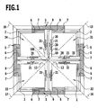
- FIG. 1 shows as a first application example 1 a shaft 5 with a square cross-section. It is divided by a right-angled cross 10 into four equal segments 11, 12, 13, 14. Each of the segments 11, 12, 13, 14 is equipped with a roadway.
- the legs 9 of the cross 10 are provided on each side with vertical guide rails 21.
- the guide rails 21 for a segment are at right angles to each other. They are designed in the example for the operation of self-propelled cabins 31, 32, 33 34 with its own friction wheel drive.
- rollers 20 are pressed, which are equipped for this purpose with a controlled drive.
- the energy is supplied via vertical busbars (not shown).
- the four lanes are arranged such that an axis 15, 16, 17, 18 laid horizontally through the outer corner 2 of the cabins 31, 32, 33, 34, the center 100 of a likewise through the outer corners 2 of the cabins 31, 32, 33 , 34 current, imaginary circle meets, said center 100 simultaneously forms the center of the elevator shaft 5 and the inserted transfer devices.
- the conversion device is used to change a car from one shaft to another.
- the cabin moves for this purpose from above or below in the height of a cabin exhibiting, rotatably mounted turnstile.
- the conversion process is carried out by a horizontal rotation with the cabin to the right or left. If the rotatable segment with the cabin is located exactly above the desired segment in the shaft, the turnstile is electrically and mechanically locked. The cabin can then continue up or down.
- the transmission of energy and optionally the transmission of information from the stationary shaft to the turnstile takes place, for example, by means of slip ring contacts or flexible lines.
- the information transfer can z. B. done wirelessly by a transmitting and receiving device.
- FIG. 4 shows the top view of a turning device 410 formed as a conversion device with four equal segments 411, 412, 413, 414 for receiving four square cabins with corner entry.
- the Umsetzz worn is round, has the height of a floor of the building and is designed by its own drive to the right and left rotating. It is enclosed by a circular fixed shaft wall 45. In the shaft wall 45 for each of the segments 411, 413, 414, 415 round, centrally opening sliding doors 47 are embedded with their own drive.
- the axis of the turnstile 410 is mounted on the center of the shaft cross 10.
- Each of the segments 411, 412, 413, 414 of the turnstile 410 is provided with a roadway.
- the legs 409 of the turnstile 410 are provided on each side with vertical guide rails 21.
- the diameter of the turnstile 410 corresponds to the distance of the axis 16, 18 between the outer corners of the opposite cabins z. B. 32, 34.
- the segments 411, 412, 413, 414 of the hub 410 between the legs 409 are limited to the shaft wall 45 with rotating door sills 44. To the right and left of these floor to ceiling covers 49 are attached.
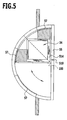
- FIG. 5 shows the top view of a reduced conversion device in the form of a turnstile 510 with a right or left pivotable cabin 34.
- the shaft wall 55 is configured semicircular, and in the shaft wall 55 sliding doors 57 are embedded. This in FIG. 5 illustrated hub 510 is executed only to a quarter and defines a segment 514. Otherwise, the design with that in FIG. 4 identical.
- the fourfold shaft in FIG. 1 , the double shaft in FIG. 2 and the simple bay in FIG. 3 can with the turnstiles in FIG. 4 and FIG. 5 be combined in a variety of variants.
- two of each of the four shafts may form an independent roundabout.
- two shafts serve the main traffic direction and the third shaft is used for the retrieval of the cabins.
- the fourth shaft serves as a reserve.
- a reduced solution is the double shaft in FIG. 2 along with half the turnstile in FIG. 5 This makes it possible to build a complete roundabout with several cabins.
- FIG. 6 a rectangular shaft 65, which is divided by a swastika 610 into four rectangular segments 611, 612, 613, 614. Each of the segments 611, 612, 613, 614 is provided with a roadway.
- the mutually parallel legs 609 of the shaft cross 610 are provided per segment on the inside with vertical guide rails 621. The leg therebetween carries the active or passive part 603 of a linear motor.
- the counterpart 604 thereto sits on the respective cabin 631, 632, 633, 634.
- the four separate track segments 611, 612, 613, 614 are in turn arranged so that an axis 601, 602 placed horizontally through the outer corner of the cars will cover the center 100 of one also through the outer corners of the cars 631, 632, 633 , 634 running imaginary circle, this center 100 also forms the center of the swastika 610 and the inserted Umsetzr sensibleen.
- the cabins 631, 632, 633, 634 and the shaft 65 are each provided with laterally-opening sliding doors 67, 66.
- the quadruple shaft 65 in FIG. 6 can also be realized as in Application Example 1 with two or only one segment.
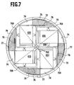
- FIG. 7 is a transfer device shown with a turnstile in the form of a swastika 710 with legs 709 and rectangular cabins 631, 632, 633, 634 and laterally opening sliding doors 76.
- the latter release door sills 74, which are arranged laterally next to covers 79.
- the turnstile 710 is also equipped as the shaft 65 for the linear drive. Round, single-leaf shaft doors 77 each have their own drive.
- the transfer device in FIG. 7 can be realized in the economy version as a semicircle with a swiveling segment for receiving a cabin.
Landscapes
- Engineering & Computer Science (AREA)
- Structural Engineering (AREA)
- Architecture (AREA)
- Automation & Control Theory (AREA)
- Civil Engineering (AREA)
- Types And Forms Of Lifts (AREA)
- Elevator Control (AREA)
- Elevator Door Apparatuses (AREA)
- Lift-Guide Devices, And Elevator Ropes And Cables (AREA)
Description
- Die Erfindung betrifft ein Verhehrssystem mit den Merkmalen des Oberbegriffes von Patentanspruch 1.
- Der vertikale Transport in Gebäuden wird heute im Wesentlichen mit Seil- oder Hydraulik-Aufzügen bewerkstelligt. Bedingt durch die Bauart benötigt jede Kabine eines Aufzuges exklusiv einen eigenen Schacht. Das heißt es können nicht mehrere Kabinen gleichzeitig eine Fahrbahn des Schachtes nutzen. Bei hohen Gebäuden werden dadurch bis zum 30 % des umbauten Raumes allein für die Aufzugsschächte benötigt.
- Wirtschaftlicher sind Systeme, bei denen je nach Verkehrsaufkommen mehrere Kabinen dieselbe Fahrbahn im Aufzugsschacht benutzen. Damit kann die Transportleistung im Vergleich zu herkömmlichen Aufzügen bei weniger umbautem Raum erheblich gesteigert werden.
- Inzwischen ist das erste System auf dem Markt, bei dem sich zwei konventionelle Aufzüge mit Gegengewicht einen Aufzugsschacht teilen. Dadurch wird die Schachtaushutzung um fast das Doppelte gesteigert. Diese Lösung hat jedoch den Nachteil, dass nicht jede der beiden Kabinen die Endhaltestelle erreichen kann. Zudem sind die Möglichkeiten, mehr als zwei Kabinen pro Schacht einzusetzen, durch die Seile und Gegengewichte begrenzt.
- Eine bessere und flexiblere Schachtausnutzung wird mit selbstfahrenden Kabinen, die z. B. mittels Linearmotor oder Reibrad angetrieben sind, erreicht. Die im weiteren beschriebene Lösung geht von solchen selbstfahrenden Kabinen im Aufzugsschacht aus.
- In Veröffentlichungen und Patentschriften werden eine Vielzahl von Lösungen für die Mehrfachnutzung von Aufzugschächten beschrieben. Meist sehen diese Lösungen einen Kreisverkehr der Kabinen in mindestens zwei Aufzugsschächten vor. Es können dann je nach Verkehrsaufkommen beliebig viele Kabinen in den Verkehr gebracht werden. Der Verkehrsfluss im Schacht bewegt sich zudem nur in einer Richtung, wodurch die technische Auslegung des Gesamtsystems vereinfacht und die Kollisionsgefahr reduziert wird.
- Bisher sind solche Systeme nicht zur Anwendung gelangt, da für das Schachtsystem und insbesondere für die Umsetzung der selbstfahrenden Kabinen von einem Schacht in den anderen keine wirtschaftliche Lösung gefunden wurde.
- Das Gebrauchsmuster
DE 202 06 290 U1 beschreibt ein einfaches System. Die beschriebene Lösung setzt allerdings ein zylinderförmiges Schachtsystem voraus. Auch die Kabinen müssen die Form eines Teilzylinders aufweisen. Dies hat zur Folge, dass sowohl die Schachttüren als auch die Kabinentüren rund auszuführen sind, was die Herstellungskosten erheblich verteuert. Kabinen und Schacht sind zudem als Teilzylinder zu realisieren, was zumindest in der Anwendung gewöhnungsbedürftig ist. - Aufgabe der vorliegenden Erfindung ist es, einen Aufzugsschacht der eingangs genannten Art derart auszugestalten, dass mehrere Aufzugskabinen gemeinsam eine Fahrbahn in einem viereckigen Schacht nutzen können.
- Diese Aufgabe wird durch einen Aufzugsschacht mit den Merkmalen von Patentanspruch 1 gelöst.
- Die mit der Erfindung erzielten Vorteile bestehen insbesondere darin, dass sich das Prinzip der gleichzeitigen Nutzung einer Fahrbahn durch mehrere Kabinen in der heute üblichen Bauweise mit eckigen Schächten und Kabinen wirtschaftlich realisieren lässt. Die Erfindung ermöglicht die Nutzung eines Aufzugsschachtes mit nur einer Fahrbahn durch bis zu vier selbstfahrende Kabinen.
- In einen voll ausgebauten Aufzugsschacht können bis zu vier voneinander unabhängige Fahrbahnen parallel eingesetzt werden.
- Bei entsprechender Ausstattung der Fahrbahnen können die selbstfahrenden Kabinen mit Linearmotor oder Reibradantrieb oder gemischt eingesetzt werden.
- Die Verknüpfung der Fahrbahnen wird mit einer Umsetzeinrichtung bewerkstelligt, die an beliebiger Stelle in den Schacht positionierbar ist.
- Die mulitfunktionale Umsetzeinrichtung ermöglicht das Zwischenparken und den Wechsel der Kabinen von einer Fahrbahn zur anderen. Damit können die unterschiedlichsten Anforderungen abgedeckt werden, wie z. B. Kreisverkehr, Überholen oder Anpassen der Kabinendichte an das Verkehrsaufkommen.
- Da die Kabinen wie bei einem Bahnhof von beiden Seiten in die Umsetzeinrichtung einfahren können, kann ein besonders guter Katastrophenschutz erzielt werden. Besonders wenn ein Gebäude in der Mitte durch eine Explosion ganz oder teilweise zerstört ist.
- Um diesen Katastrophenschutz zu erreichen, werden in regelmäßigen Abständen Umsetzeinrichtungen in einen Schacht mit mindestens zwei Fahrbahnen positioniert. Wird ein Gebäude einschließlich des Schachtes in der Mitte zerstört, setzt die Steuerung den betroffenen Abschnitt außer Betrieb. Für den darunter und den darüber liegenden Gebäudebereich kann im Schacht ein eigenständiger Kreisverkehr den Betrieb weiter aufrecht erhalten.
- Ziel der Erfindung ist es, ein wirtschaftliches Verkehrssystem für den Personentransport in Gebäuden zu schaffen, das die unterschiedlichsten Anforderungen erfüllt und sich trotzdem in einem hohen Maße standardisieren lässt.
- Zwei Ausführungsbeispiele werden im Folgenden beschrieben. Beide erfüllen im Wesentlichen dieselben Funktionen.
- Das Verkehrssystem besteht aus einem Mehrfachschacht und einer Umsetzeinrichtung. Der vollausgebaute viereckige Mehrfachschacht unterteilt sich in vier gleichartige Segmente. Jedes Segment enthält eine Fahrbahn für den gleichzeitigen Betrieb von mehreren selbstfahrenden Kabinen. Fahrbahnen und Kabinen können für verschiedene Antriebsarten ausgestattet werden, zum Beispiel für Reibrad- oder Linearmotorantrieb. Auch ein gemischter Betrieb ist möglich.
- Den Anfangs- oder Endbahnhof des Gesamtsystems bildet die Umsetzeinrichtung. Die Umsetzeinrichtung kann auch als Zwischenstation an beliebiger Stelle im Schacht eingefügt werden.
- Die Umsetzeinrichtung wirkt wie ein mulitfunktionaler Vekehrsknoten. Sie ermöglicht den Kabinen den Fahrbahnwechsel, die Richtungsumkehr, das Überholen und das Zwischenparken. Die Umsetzeinrichtungen können aber auch von den Kabinen, auf derselben Fahrbahn bleibend, einfach durchfahren werden. Bei Anwendung der Umsetzeinrichtungen als Zwischenstation ist der Verkehr in höheren Gebäuden in größere Abschnitte unterteilbar. Damit kann bei Unfällen im Gebäude der betroffene Abschnitt stillgelegt werden, ohne Beeinträchtigung der darüber oder darunter liegenden Abschnitte.
- Zwei ausgewählte Ausführungsbeispiele der Erfindung sind in der Zeichnung dargestellt und im Folgenden beschrieben. Es zeigen:
- Figur 1:
- einen Horizontalschnitt eines viereckigen Mehrfachschachtes mit Eckeinstieg und vier parallelen Fahrbahnen;
- Figur 2:
- einen Horizontalschnitt eines viereckigen Mehrfachschachtes mit Eckeinstieg und zwei parallelen Fahrbahnen (nich Teil der Erfindung);
- Figur 3:
- einen Horizontalschnitt eines viereckigen Mehrfachschachtes mit Eckeinstieg und einer Fahrbahn (nich Teil der Erfindung);
- Figur 4:
- eine Draufsicht einer als Drehkreuz ausgebildeten Umsetzeinrichtung mit vier Segmenten zur Aufnahme von vier quadratischen Kabinen;
- Figur 5:
- eine Draufsicht einer als Halbkreis ausgebildeten Umsetzeinrichtung mit einem nach rechts oder links schwenkbaren Segment zur Aufnahme von einer quadratischen Kabine (nicht Teil der Erfindung);
- Figur 6:
- einen Horizontalschnitt eines viereckigen Mehrfachschachtes mit vier parallelen Fahrbahnen, ausgelegt für rechteckige Kabinen mit seitlicher Schiebetüre;
- Figur 7:
- eine Draufsicht einer als Hakendrehkreuz ausgebildeten Umsetzeinrichtung mit vier Segmenten zur Aufnahme einer rechteckigen Kabine mit seitlicher Schiebetüre.
-
Figur 1 zeigt als ein erstes Anwendungsbeispiel 1 einen Schacht 5 mit quadratischem Querschnitt. Er wird durch ein rechtwinkliges Kreuz 10 in vier gleiche Segmente 11, 12, 13, 14 unterteilt. Jedes der Segmente 11, 12, 13, 14 ist mit einer Fahrbahn ausgestattet. Die Schenkel 9 des Kreuzes 10 sind dazu auf jeder Seite mit vertikalen Führungsschienen 21 versehen. Die Führungsschienen 21 für ein Segment stehen im rechten Winkel zueinander. Sie sind im Beispiel für den Betrieb selbstfahrender Kabinen 31, 32, 33 34 mit eigenem Reibradantrieb ausgelegt. An die Schienen 21 sind jeweils Rollen 20 angepresst, die hierzu mit einem geregelten Antrieb ausgerüstet sind. Die Energiezufuhr erfolgt über vertikale Stromschienen (nicht eingezeichnet). Die vier Fahrbahnen sind so angeordnet, dass eine horizontal durch die außen liegende Ecke 2 der Kabinen 31, 32, 33 34 gelegte Achse 15, 16, 17, 18 das Zentrum 100 eines ebenfalls durch die äußeren Ecken 2 der Kabinen 31, 32, 33, 34 laufenden, gedachten Kreises trifft, wobei dieses Zentrum 100 gleichzeitig den Mittelpunkt des Aufzugsschachtes 5 und der eingefügten Umsetzeinrichtungen bildet. - Die Kabinen 31, 32, 33, 34 und die vier Schachtsegmente 11, 12, 13, 14 haben jeweils einen Eckeinstieg. Kabinentüren 6 und Schachttüren 7 laufen hierzu rechtwinklig aufeinander zu und treffen sich auf den Achsen 15, 16, 17, 18.
-
Figur 2 zeigt den inFigur 1 dargestellten Schacht 5 als Teilschacht 5.2 in identischer Bauform, jedoch mit nur zwei nebeneinander angeordneten Segmenten bzw. Fahrbahnen. -
Figur 3 zeigt für kleine Anwendungen den inFigur 1 dargestellten Schacht 5 als Teilschacht 5.3 in identischer Bauform mit nur einem Segment bzw. einer Fahrbahn. - Die Umsetzeinrichtung dient vor allem dem Wechsel einer Kabine von einem Schacht in einen anderen. Die Kabine fährt hierzu von oben oder unten in ein die Höhe einer Kabine aufweisendes, drehbar gelagertes Drehkreuz ein. Der Umsetzvorgang wird durch eine horizontale Drehbewegung mit der Kabine nach rechts oder links ausgeführt. Steht das drehbare Segment mit der Kabine exakt über dem gewünschten Segment im Schacht, wird das Drehkreuz elektrisch und mechanisch verriegelt. Die Kabine kann dann ihre Fahrt nach oben oder unter fortsetzen. Die Energieübertragung und gegebenenfalls die Informationsübertragung vom stationären Schacht zum Drehkreuz findet zum Beispiel mittels Schleifringkontakten oder flexiblen Leitungen statt. Die Informationsübertragung kann z. B. drahtlos durch eine Sende- und Empfangseinrichtung erfolgen.
-
Figur 4 zeigt die Draufsicht einer als Drehkreuz 410 ausgebildeten Umsetzeinrichtung mit vier gleichen Segmenten 411, 412, 413, 414 zur Aufnahme von vier quadratischen Kabinen mit Eckeinstieg. - Die Umsetzeinrichtung ist rund, hat die Höhe eines Stockwerkes des Gebäudes und ist durch einen eigenen Antrieb nach rechts und links drehend ausgeführt. Sie wird von einer kreisförmigen feststehenden Schachtwand 45 umschlossen. In die Schachtwand 45 sind für jedes der Segmente 411, 413, 414, 415 runde, zentral öffnende Schiebetüren 47 mit eigenem Antrieb eingelassen. Die Achse des Drehkreuzes 410 ist auf dem Mittelpunkt des Schachtkreuzes 10 gelagert. Jedes der Segmente 411, 412, 413, 414 des Drehkreuzes 410 ist mit einer Fahrbahn ausgestattet. Die Schenkel 409 des Drehkreuzes 410 sind dazu auf jeder Seite mit vertikalen Führungsschienen 21 versehen. Der Durchmesser des Drehkreuzes 410 entspricht der Distanz der Achse 16, 18 zwischen den äußeren Ecken der gegenüberliegenden Kabinen z. B. 32, 34. Die Segmente 411, 412, 413, 414 des Drehkreuzes 410 zwischen den Schenkeln 409 werden zur Schachtwand 45 mit drehenden Türschwellen 44 begrenzt. Rechts und links von diesen sind raumhohe Abdeckungen 49 angebracht.
-
Figur 5 zeigt die Draufsicht einer reduzierten Umsetzeinrichtung in Form eines Drehkreuzes 510 mit einer nach rechts oder links schwenkbaren Kabine 34. Die Schachtwand 55 ist halbkreisförmig ausgestaltet, und in die Schachtwand 55 sind Schiebetüren 57 eingelassen. Das inFigur 5 dargestellte Drehkreuz 510 ist nur zu einem Viertel ausgeführt und definiert ein Segment 514. Ansonsten ist die Bauform mit derjenigen inFigur 4 identisch. - Der vierfache Schacht in
Figur 1 , der zweifache Schacht inFigur 2 und der einfache Schacht inFigur 3 können mit den Drehkreuzen inFigur 4 undFigur 5 in den verschiedensten Varianten kombiniert werden. - Bei der Kombination des vierfachen Schachtes von
Figur 1 mit dem kompletten Drehkreuz inFigur 4 können zum Beispiel jeweils zwei der vier Schächte einen unabhängigen Kreisverkehr bilden. In einer anderen Variante bedienen zwei Schächte die Hauptverkehrsrichtung und der dritte Schacht wird für die Rückholung der Kabinen eingesetzt. Der vierte Schacht dient als Reserve. - Eine reduzierte Lösung stellt der zweifache Schacht in
Figur 2 zusammen mit dem halben Drehkreuz inFigur 5 dar. Damit lässt sich ein kompletter Kreisverkehr mit mehreren Kabinen aufbauen. - Die kleinste Lösung ergibt sich, indem der Einzelschacht in
Figur 3 mit dem Drehkreuz inFigur 4 kombiniert wird. Mit dieser Kombination können bis zu vier Kabinen hintereinander entlang des Schachtes nach oben in ein oberes Drehkreuz einfahren. Danach wird die Richtung umgekehrt und die vier Kabinen können in umgekehrter Reihenfolge wieder nach unten in ein unteres Drehkreuz einfahren. - Im Prinzip ist es auch möglich, den Einzelschacht nur zusammen mit einer Kabine mit oder ohne Gegengewicht zu betreiben.
- Der traditionelle Aufzugsbau geht im allgemeinen von quadratischen oder rechteckigen Kabinen aus, die mit seitlich oder zentral öffnenden Türen ausgestattet sind. Für diese Lösung sind kostengünstige Komponenten im Markt verfügbar. Als Antriebsvariante für selbst fahrende Kabinen wird dem Linearantrieb eine Zukunftsperspektive eingeräumt. Deshalb wurden bei der Gestaltung des Anwendungsbeispieles 2 diese Anforderungen berücksichtigt.
- Im Übrigen sind jedoch alle Funktionen und Anwendungsvarianten der Anwendungsbeispiele 1 und 2 identisch, so dass im Folgenden nur auf die Unterschiede in der Ausgestaltung eingegangen wird.
- Anstatt eines quadratischen Schachtes zeigt
Figur 6 einen rechteckigen Schacht 65, der durch ein Hakenkreuz 610 in vier rechteckige Segmente 611, 612, 613, 614 unterteilt ist. Jedes der Segmente 611, 612, 613, 614 ist mit einer Fahrbahn ausgestattet. Die parallel zueinander verlaufenden Schenkel 609 des Schachtkreuzes 610 sind pro Segment auf der Innenseite mit vertikalen Führungsschienen 621 versehen. Der Schenkel dazwischen trägt den aktiven oder den passiven Teil 603 eines Linearmotors. Das Gegenstück 604 dazu sitzt auf der jeweiligen Kabine 631, 632, 633, 634. - Die vier Segmente 611, 612, 613, 614 mit jeweils eigenständiger Fahrbahn sind wiederum so angeordnet, dass eine horizontal durch die außen liegende Ecke der Kabinen gelegte Achse 601, 602 das Zentrum 100 eines ebenfalls durch die äußeren Ecken der Kabinen 631, 632, 633, 634 verlaufenden gedachten Kreises trifft, wobei dieses Zentrum 100 gleichzeitig den Mittelpunkt des Hakenkreuzes 610 und der eingefügten Umsetzreinrichtungen bildet.
- Die Kabinen 631, 632, 633, 634 und der Schacht 65 sind jeweils mit seitlich öffnenden Schiebetüren 67, 66 ausgestattet.
- Der vierfache Schacht 65 in
Figur 6 kann wie im Anwendungsbeispiel 1 ebenfalls mit zwei oder nur mit einem Segment realisiert werden. - In
Figur 7 ist eine Umsetzeinrichtung dargestellt mit einem Drehkreuz in Form eines Hakenkreuzes 710 mit Schenkeln 709 sowie mit rechteckigen Kabinen 631, 632, 633, 634 und seitlich öffnenden Schiebetüren 76. Letztere geben Türschwellen 74 frei, die seitlich neben Abdeckungen 79 angeordnet sind. Das Drehkreuz 710 ist zudem wie der Schacht 65 für den Linearantrieb ausgestattet. Runde, einflügelige Schachttüren 77 verfügen jeweils über einen eigenen Antrieb. - Die Umsetzeinrichtung in
Figur 7 kann in der Sparversion auch als Halbkreis mit einem schwenkbaren Segment für die Aufnahme einer Kabine realisiert werden.
Claims (16)
- Verhehrssystem bestehend aus einem Aufzugsschacht mit bis zu vier parallelen, gleichartigen Fahrbahnen, eingerichtet für den Betrieb von mehreren selbstfahrenden Kabinen (31, 32, 33, 34) pro Fahrbahn, und mit mindestens einer Umsetzeinrichtung (410, 510, 710) zum Wechseln der Fahrbahn, zum Zwischenparken, Wenden und Überholen von Kabinen (31, 32, 33, 34), dadurch gekennzeichnet, dass der Aufzugsschacht (5, 65) einen viereckigen Querschnitt aufweist mit bis zu vier Segmenten (11, 12, 13, 14; 611, 612, 613, 614) mit jeweils eigenständiger Fahrbahn, wobei die Segmente (11, 12, 13, 14; 611, 612, 613, 614) jeweils so angeordnet sind, dass eine horizontal durch die außen liegende Ecke der Kabinen (31, 32, 33, 34) gelegte Achse (15, 16, 17, 18; 601, 602) das Zentrum (100) eines ebenfalls durch die äußeren Ecken der Kabinen (31, 32, 33, 34) verlaufenden gedachten Kreises trifft, wobei dieses Zentrum (100) gleichzeitig den Mittelpunkt des Aufzugsschachtes (5, 65) und der eingefügten Umsetzeinrichtungen (410, 510, 710) bildet.
- Verhehrssystem nach Anspruch 1, dadurch gekennzeichnet, dass der Aufzugsschacht als Teilschacht (5.1, 5.2) mit einem, zwei oder drei Segmenten ausgeführt ist.
- Verhehrssystem nach Anspruch 1, dadurch gekennzeichnet, dass die Umsetzeinrichtung (410, 510, 710) als rechtwinkliges Drehkreuz mit bis zu vier Segmenten zur Aufnahme von maximal vier Kabinen (31, 32, 33, 34) ausgebildet ist.
- Verhehrssystem nach Anspruch 3, dadurch gekennzeichnet, dass die Umsetzeinrichtung (410, 510, 710) am Anfang und am Ende des Schachtes (5, 65) oder an einem beliebigen Haltepunkt in den Schacht (5, 65) eingefügt ist.
- Verhehrssystem nach Anspruch 1, dadurch gekennzeichnet, dass der Einstieg in Schacht und Kabine über Eck erfolgt und dementsprechend die Türflügel (6, 7) von Schacht- und Kabinentüren im rechten Winkel aufeinander stoßen.
- Verhehrssystem nach Anspruch 3, dadurch gekennzeichnet, dass das Drehkreuz (710) als Hakenkreuz ausgeführt ist.
- Verhehrssystem nach Anspruch 6, dadurch gekennzeichnet, dass der Einstieg in die Kabine (31, 32, 33, 34) durch die außenliegende Stirnfläche und durch gerade Aufzugstüren (76) erfolgt.
- Verhehrssystem nach einem der voranstehenden Ansprüche, dadurch gekennzeichnet, dass die Schachttüren (47) der Umsetzeinrichtung (410) mit einem eigenständigen Antrieb ausgerüstet sind.
- Verhehrssystem nach einem der voranstehenden Ansprüche, dadurch gekennzeichnet, dass die Fahrbahnen im Schacht für den Betrieb von Kabinen (31, 32, 33, 34) mit Linearmotor (603, 604) ausgerüstet sind.
- Verhehrssystem nach einem der voranstehenden Ansprüche, dadurch gekennzeichnet, dass die Fahrbahnen im Schacht für den Betrieb von Kabinen (31, 32, 33, 34) mit Reibradantrieb (20, 21) ausgerüstet sind.
- Verhehrssystem nach Anspruch 3, dadurch gekennzeichnet, dass die Segmente des Drehkreuzes (410, 510, 710) oben und unten offen sind und die Kabinen (31, 32, 33, 34) von oben oder unten in das Segment einfahren oder auch durch dieses hindurch fahren können.
- Verhehrssystem nach Anspruch 3, dadurch gekennzeichnet, dass das Drehkreuz (410, 510, 710) mit einer Verriegelungseinrichtung und einer Signalisierungseinrichtung ausgerüstet ist, die dann aktiv werden, wenn nach einer Drehbewegung die Segmente (411, 412, 413, 414; 514) wieder passgenau über den Fahrbahnen stehen.
- Verhehrssystem nach Anspruch 1, dadurch gekennzeichnet, dass der Aufzugsschacht (65) eine rechteckige Grundfläche und die Umsetzeinrichtung (710) eine kreisförmige Grundfläche aufweist.
- Verhehrssystem nach einem der voranstehenden Ansprüche, dadurch gekennzeichnet, dass mehrere Umsetzeinrichtungen (410, 510, 710) übereinander positionierbar sind.
- Verhehrssystem nach einem der voranstehenden Ansprüche, dadurch gekennzeichnet, dass die Fahrbahnen im Schacht (5; 65) einschließlich der Umsetzeinrichtung (410, 510, 710) für den gemischten Betrieb von Kabinen mit Reibradantrieb und Linearmotor ausgerüstet sind.
- Verhehrssystem nach Anspruch 3, dadurch gekennzeichnet, dass die Umsetzeinrichtung (510) als Halbkreis mit einem nach rechts und links schwenkenden Segment (514) zur Aufnahme von maximal einer Kabine (34) ausgebildet ist.
Applications Claiming Priority (2)
| Application Number | Priority Date | Filing Date | Title |
|---|---|---|---|
| DE202004009022U DE202004009022U1 (de) | 2004-06-07 | 2004-06-07 | Aufzugsschacht für selbstfahrende Kabinen |
| PCT/EP2005/005830 WO2005121010A1 (de) | 2004-06-07 | 2005-05-31 | Aufzugsschacht |
Publications (2)
| Publication Number | Publication Date |
|---|---|
| EP1758809A1 EP1758809A1 (de) | 2007-03-07 |
| EP1758809B1 true EP1758809B1 (de) | 2012-10-03 |
Family
ID=32981538
Family Applications (1)
| Application Number | Title | Priority Date | Filing Date |
|---|---|---|---|
| EP05751628A Expired - Lifetime EP1758809B1 (de) | 2004-06-07 | 2005-05-31 | Aufzugsschacht |
Country Status (8)
| Country | Link |
|---|---|
| US (1) | US20070181374A1 (de) |
| EP (1) | EP1758809B1 (de) |
| JP (1) | JP2008501596A (de) |
| CN (1) | CN100569622C (de) |
| DE (1) | DE202004009022U1 (de) |
| ES (1) | ES2396716T3 (de) |
| RU (1) | RU2388681C2 (de) |
| WO (1) | WO2005121010A1 (de) |
Cited By (1)
| Publication number | Priority date | Publication date | Assignee | Title |
|---|---|---|---|---|
| CN109422161A (zh) * | 2017-08-19 | 2019-03-05 | 周立波 | 一种智能多轿厢电梯 |
Families Citing this family (25)
| Publication number | Priority date | Publication date | Assignee | Title |
|---|---|---|---|---|
| US20070209292A1 (en) * | 2006-03-13 | 2007-09-13 | Broyan Frederick K | Corner lift device |
| EP2070860A1 (de) * | 2007-12-11 | 2009-06-17 | Inventio Ag | Aufzugssystem mit vertikal und horizontal verfahrbaren Aufzugkabinen |
| EP2161233B1 (de) * | 2008-09-01 | 2012-02-01 | ThyssenKrupp Elevator AG | Tragvorrichtung zum Umsetzen eines Fahrkorbs eines Aufzugs |
| EP2370333B1 (de) * | 2008-12-26 | 2013-08-28 | Inventio AG | Aufzugsanlage mit einer sicherheitseinrichtung |
| GB2473025A (en) * | 2009-08-26 | 2011-03-02 | Waycon Precast Ltd | Prefabricated concrete twin lift shaft assembly |
| CN103209919B (zh) * | 2010-08-06 | 2016-06-15 | 科尔伊埃莱瓦托株式会社 | 一种升降装置及电梯系统 |
| US8430210B2 (en) | 2011-01-19 | 2013-04-30 | Smart Lifts, Llc | System having multiple cabs in an elevator shaft |
| US8925689B2 (en) | 2011-01-19 | 2015-01-06 | Smart Lifts, Llc | System having a plurality of elevator cabs and counterweights that move independently in different sections of a hoistway |
| WO2014158127A1 (en) * | 2013-03-25 | 2014-10-02 | Otis Elevator Company | Multicar self-propelled elevator system |
| US10246298B2 (en) | 2013-12-05 | 2019-04-02 | Otis Elevator Company | Ropeless elevator system |
| KR102534081B1 (ko) * | 2015-01-23 | 2023-05-19 | 오티스 엘리베이터 컴파니 | 엘리베이터 시스템 레일 |
| CN104671037B (zh) * | 2015-03-20 | 2017-03-15 | 中建三局集团有限公司 | 智能旋转换轨控制系统及方法 |
| EP3106418B1 (de) * | 2015-06-17 | 2020-09-30 | KONE Corporation | Lösung zum bewegen einer aufzugskabine |
| US10370222B2 (en) * | 2015-07-16 | 2019-08-06 | Otis Elevator Company | Ropeless elevator system and a transfer system for a ropeless elevator system |
| US10865072B2 (en) | 2015-08-03 | 2020-12-15 | Otis Elevator Company | Intermediate transfer station |
| DE102016211997A1 (de) | 2016-07-01 | 2018-01-04 | Thyssenkrupp Ag | Aufzugsanlage |
| US10494229B2 (en) | 2017-01-30 | 2019-12-03 | Otis Elevator Company | System and method for resilient design and operation of elevator system |
| CN107458947A (zh) * | 2017-07-31 | 2017-12-12 | 江苏速升自动化装备股份有限公司 | 一种轿厢能平移的电梯 |
| CN109795934A (zh) * | 2019-02-01 | 2019-05-24 | 陕西小溪机电科技有限公司 | 一种电梯井道 |
| CN110969655B (zh) * | 2019-10-24 | 2023-08-18 | 百度在线网络技术(北京)有限公司 | 用于检测车位的方法、装置、设备、存储介质以及车辆 |
| CN110884983B (zh) * | 2019-12-06 | 2024-05-28 | 福州快科电梯工业有限公司 | 空间立体交互式电梯驱动悬挂机构及其工作方法 |
| EP3971122A1 (de) * | 2020-09-17 | 2022-03-23 | KONE Corporation | Aufzug |
| RU2749216C1 (ru) * | 2020-11-06 | 2021-06-07 | Павел Викторович Сициховский | Приставная лифтовая шахта для лифтов с противовесом |
| RU2749215C1 (ru) * | 2020-11-06 | 2021-06-07 | Павел Викторович Сициховский | Приставная лифтовая шахта, имеющая круглое поперечное сечение |
| CN113738065A (zh) * | 2021-09-09 | 2021-12-03 | 江苏省方正电梯有限公司 | 一种一体化钢结构装配式模块化电梯井道 |
Family Cites Families (19)
| Publication number | Priority date | Publication date | Assignee | Title |
|---|---|---|---|---|
| US561223A (en) * | 1896-06-02 | hamilton | ||
| US2300630A (en) * | 1941-07-17 | 1942-11-03 | Otis Elevator Co | Vertical sliding door construction |
| SU922018A1 (ru) * | 1978-12-08 | 1982-04-23 | за витель Е. Г. Романушко | Подъемна установка |
| JPH01236186A (ja) * | 1988-03-16 | 1989-09-21 | Shiro Imafuku | 循環式エレベーターとこれを用いた立体駐車場 |
| US4946006A (en) * | 1988-04-13 | 1990-08-07 | T. K. M. Engineering Kabushiki Kaisha | Elevator apparatus with a sectored vertical shaft and a turntable for transfering elevator cages between the individual sectors |
| JPH03177290A (ja) * | 1989-12-06 | 1991-08-01 | Kumarifuto Kk | エレベータ |
| JPH0815993B2 (ja) * | 1991-04-16 | 1996-02-21 | 鹿島建設株式会社 | 追越し機能付リニアモータ駆動エレベータ |
| JPH07100586B2 (ja) * | 1991-10-17 | 1995-11-01 | 鹿島建設株式会社 | 垂直搬送装置の上昇ケージ退避機構 |
| JPH07157239A (ja) * | 1993-11-30 | 1995-06-20 | Hitachi Metals Ltd | リニアエレベータ |
| US5612518A (en) * | 1994-04-08 | 1997-03-18 | Otis Elevator Company | Linear induction motor door drive assembly for elevators |
| US5758748A (en) * | 1995-11-29 | 1998-06-02 | Otis Elevator Company | Synchronized off-shaft loading of elevator cabs |
| JPH10109863A (ja) * | 1996-10-01 | 1998-04-28 | Mitsubishi Denki Bill Techno Service Kk | エレベータ |
| US5816368A (en) * | 1997-03-20 | 1998-10-06 | Otis Elevator Company | Elevator cars switch hoistways while traveling vertically |
| US6354404B1 (en) * | 2000-05-16 | 2002-03-12 | Otis Elevator Company | Rotatable elevator system |
| CN2499382Y (zh) * | 2001-10-09 | 2002-07-10 | 林宏 | 一种高层建筑用电梯 |
| DE20206290U1 (de) * | 2002-04-20 | 2002-08-22 | Müller, Wolfgang T., 78315 Radolfzell | Mehrfachschacht mit Umsetzeinrichtung, insbesondere für Liftmobile |
| JP2004002020A (ja) * | 2002-05-27 | 2004-01-08 | Inventio Ag | 数台の自走式かごと少なくとも3つの隣接配置されたエレベータ昇降路とを備えたエレベータ設備 |
| US6990771B2 (en) * | 2002-09-18 | 2006-01-31 | Architectural Automations, L.L.C. | Inertial control system for opening and closing multiple sliding doors in a common direction |
| EP1754679A4 (de) * | 2004-06-07 | 2012-06-06 | Mitsubishi Electric Corp | Aufzugsvorrichtung |
-
2004
- 2004-06-07 DE DE202004009022U patent/DE202004009022U1/de not_active Expired - Lifetime
-
2005
- 2005-05-31 JP JP2007526244A patent/JP2008501596A/ja active Pending
- 2005-05-31 EP EP05751628A patent/EP1758809B1/de not_active Expired - Lifetime
- 2005-05-31 CN CNB2005800185717A patent/CN100569622C/zh not_active Expired - Fee Related
- 2005-05-31 RU RU2006145436/11A patent/RU2388681C2/ru not_active IP Right Cessation
- 2005-05-31 ES ES05751628T patent/ES2396716T3/es not_active Expired - Lifetime
- 2005-05-31 WO PCT/EP2005/005830 patent/WO2005121010A1/de not_active Ceased
-
2006
- 2006-12-05 US US11/634,515 patent/US20070181374A1/en not_active Abandoned
Cited By (1)
| Publication number | Priority date | Publication date | Assignee | Title |
|---|---|---|---|---|
| CN109422161A (zh) * | 2017-08-19 | 2019-03-05 | 周立波 | 一种智能多轿厢电梯 |
Also Published As
| Publication number | Publication date |
|---|---|
| EP1758809A1 (de) | 2007-03-07 |
| WO2005121010A1 (de) | 2005-12-22 |
| US20070181374A1 (en) | 2007-08-09 |
| CN100569622C (zh) | 2009-12-16 |
| RU2006145436A (ru) | 2008-07-27 |
| JP2008501596A (ja) | 2008-01-24 |
| CN101010252A (zh) | 2007-08-01 |
| RU2388681C2 (ru) | 2010-05-10 |
| DE202004009022U1 (de) | 2004-09-09 |
| ES2396716T3 (es) | 2013-02-25 |
Similar Documents
| Publication | Publication Date | Title |
|---|---|---|
| EP1758809B1 (de) | Aufzugsschacht | |
| DE69102768T2 (de) | Transportsystem. | |
| DE69319079T2 (de) | Radiales, mechanisiertes Parkgaragensystem | |
| DE69200488T2 (de) | Mit einem Linearmotor angetriebener Aufzug. | |
| DE60201341T2 (de) | Hochbahn | |
| EP2234859B1 (de) | Seilbahn mit ein-/ausstiegshilfe | |
| AT406069B (de) | Parkeinrichtung | |
| DE2656622A1 (de) | Bewegliche abdeckung fuer energiefuehrungsleitungen, fuehrungsbahnen und sonstige einrichtungen | |
| EP1367018B1 (de) | Aufzugsanlage mit mehreren selbstfahrenden Kabinen und mindestens drei nebeneinander angeordneten Aufzugsschächten | |
| WO2003072412A1 (de) | Magnetschnellbahnsystem mit doppelstöckiger fahrbahn | |
| EP1302431B1 (de) | Seilaufzugsystem mit zwei Fahrkörben mit gemeinsamen und getrennten Farhbahnabschnitten | |
| DE1965142A1 (de) | Einrichtung zum Parken zweier Fahrzeuge uebereinander | |
| DE20206290U1 (de) | Mehrfachschacht mit Umsetzeinrichtung, insbesondere für Liftmobile | |
| DE2651983A1 (de) | Station von transportlinien | |
| DE102004025664A1 (de) | Aufzug mit individuellem Elektroantrieb | |
| EP3774627B1 (de) | Verfahren zum betreiben einer aufzugsanlage | |
| EP1693331A1 (de) | Aufzugssystem mit mehreren Schächten und mit Aufzugskabinen welche vom gewählten Antriebssystem an- und abgekuppelt werden können | |
| EP1479636A1 (de) | Puffer zum Schaffen einer Schutzzone in einer Aufzugsanlage | |
| DE1430997B2 (de) | Anlage fur Schienenbahnen | |
| DE1918559A1 (de) | Fahrzeugparksystem | |
| EP0195370A2 (de) | Aufzug zum Transport von Personen und Gütern mit einer ringförmigen Fahrkabine | |
| WO2019086124A1 (de) | Transportsystem und verfahren zum betreiben eines derartigen transportsystems | |
| EP1479637B1 (de) | Puffer und aufzugsanlage mit einem solchen puffer | |
| DE2302145C3 (de) | Einrichtung für eine Mehrfachgarage | |
| EP4313833B1 (de) | Fahrkorbanordnung für einen doppelstockaufzug und doppelstockaufzug |
Legal Events
| Date | Code | Title | Description |
|---|---|---|---|
| PUAI | Public reference made under article 153(3) epc to a published international application that has entered the european phase |
Free format text: ORIGINAL CODE: 0009012 |
|
| 17P | Request for examination filed |
Effective date: 20061205 |
|
| AK | Designated contracting states |
Kind code of ref document: A1 Designated state(s): AT BE BG CH CY CZ DE DK EE ES FI FR GB GR HU IE IS IT LI LT LU MC NL PL PT RO SE SI SK TR |
|
| DAX | Request for extension of the european patent (deleted) | ||
| GRAP | Despatch of communication of intention to grant a patent |
Free format text: ORIGINAL CODE: EPIDOSNIGR1 |
|
| GRAS | Grant fee paid |
Free format text: ORIGINAL CODE: EPIDOSNIGR3 |
|
| GRAA | (expected) grant |
Free format text: ORIGINAL CODE: 0009210 |
|
| RAP1 | Party data changed (applicant data changed or rights of an application transferred) |
Owner name: THYSSENKRUPP ELEVATOR AG |
|
| AK | Designated contracting states |
Kind code of ref document: B1 Designated state(s): AT BE BG CH CY CZ DE DK EE ES FI FR GB GR HU IE IS IT LI LT LU MC NL PL PT RO SE SI SK TR |
|
| REG | Reference to a national code |
Ref country code: GB Ref legal event code: FG4D Free format text: NOT ENGLISH |
|
| REG | Reference to a national code |
Ref country code: CH Ref legal event code: EP Ref country code: AT Ref legal event code: REF Ref document number: 577885 Country of ref document: AT Kind code of ref document: T Effective date: 20121015 |
|
| REG | Reference to a national code |
Ref country code: IE Ref legal event code: FG4D Free format text: LANGUAGE OF EP DOCUMENT: GERMAN |
|
| REG | Reference to a national code |
Ref country code: CH Ref legal event code: NV Representative=s name: ISLER & PEDRAZZINI AG |
|
| REG | Reference to a national code |
Ref country code: DE Ref legal event code: R096 Ref document number: 502005013150 Country of ref document: DE Effective date: 20121129 |
|
| REG | Reference to a national code |
Ref country code: NL Ref legal event code: T3 |
|
| REG | Reference to a national code |
Ref country code: ES Ref legal event code: FG2A Ref document number: 2396716 Country of ref document: ES Kind code of ref document: T3 Effective date: 20130225 |
|
| PG25 | Lapsed in a contracting state [announced via postgrant information from national office to epo] |
Ref country code: SI Free format text: LAPSE BECAUSE OF FAILURE TO SUBMIT A TRANSLATION OF THE DESCRIPTION OR TO PAY THE FEE WITHIN THE PRESCRIBED TIME-LIMIT Effective date: 20121003 |
|
| REG | Reference to a national code |
Ref country code: LT Ref legal event code: MG4D |
|
| PG25 | Lapsed in a contracting state [announced via postgrant information from national office to epo] |
Ref country code: SE Free format text: LAPSE BECAUSE OF FAILURE TO SUBMIT A TRANSLATION OF THE DESCRIPTION OR TO PAY THE FEE WITHIN THE PRESCRIBED TIME-LIMIT Effective date: 20121003 Ref country code: LT Free format text: LAPSE BECAUSE OF FAILURE TO SUBMIT A TRANSLATION OF THE DESCRIPTION OR TO PAY THE FEE WITHIN THE PRESCRIBED TIME-LIMIT Effective date: 20121003 Ref country code: IS Free format text: LAPSE BECAUSE OF FAILURE TO SUBMIT A TRANSLATION OF THE DESCRIPTION OR TO PAY THE FEE WITHIN THE PRESCRIBED TIME-LIMIT Effective date: 20130203 |
|
| PG25 | Lapsed in a contracting state [announced via postgrant information from national office to epo] |
Ref country code: CY Free format text: LAPSE BECAUSE OF FAILURE TO SUBMIT A TRANSLATION OF THE DESCRIPTION OR TO PAY THE FEE WITHIN THE PRESCRIBED TIME-LIMIT Effective date: 20121003 Ref country code: PT Free format text: LAPSE BECAUSE OF FAILURE TO SUBMIT A TRANSLATION OF THE DESCRIPTION OR TO PAY THE FEE WITHIN THE PRESCRIBED TIME-LIMIT Effective date: 20130204 Ref country code: PL Free format text: LAPSE BECAUSE OF FAILURE TO SUBMIT A TRANSLATION OF THE DESCRIPTION OR TO PAY THE FEE WITHIN THE PRESCRIBED TIME-LIMIT Effective date: 20121003 Ref country code: GR Free format text: LAPSE BECAUSE OF FAILURE TO SUBMIT A TRANSLATION OF THE DESCRIPTION OR TO PAY THE FEE WITHIN THE PRESCRIBED TIME-LIMIT Effective date: 20130104 |
|
| PG25 | Lapsed in a contracting state [announced via postgrant information from national office to epo] |
Ref country code: BG Free format text: LAPSE BECAUSE OF FAILURE TO SUBMIT A TRANSLATION OF THE DESCRIPTION OR TO PAY THE FEE WITHIN THE PRESCRIBED TIME-LIMIT Effective date: 20130103 Ref country code: EE Free format text: LAPSE BECAUSE OF FAILURE TO SUBMIT A TRANSLATION OF THE DESCRIPTION OR TO PAY THE FEE WITHIN THE PRESCRIBED TIME-LIMIT Effective date: 20121003 Ref country code: SK Free format text: LAPSE BECAUSE OF FAILURE TO SUBMIT A TRANSLATION OF THE DESCRIPTION OR TO PAY THE FEE WITHIN THE PRESCRIBED TIME-LIMIT Effective date: 20121003 Ref country code: CZ Free format text: LAPSE BECAUSE OF FAILURE TO SUBMIT A TRANSLATION OF THE DESCRIPTION OR TO PAY THE FEE WITHIN THE PRESCRIBED TIME-LIMIT Effective date: 20121003 Ref country code: DK Free format text: LAPSE BECAUSE OF FAILURE TO SUBMIT A TRANSLATION OF THE DESCRIPTION OR TO PAY THE FEE WITHIN THE PRESCRIBED TIME-LIMIT Effective date: 20121003 |
|
| PLBE | No opposition filed within time limit |
Free format text: ORIGINAL CODE: 0009261 |
|
| STAA | Information on the status of an ep patent application or granted ep patent |
Free format text: STATUS: NO OPPOSITION FILED WITHIN TIME LIMIT |
|
| PG25 | Lapsed in a contracting state [announced via postgrant information from national office to epo] |
Ref country code: RO Free format text: LAPSE BECAUSE OF FAILURE TO SUBMIT A TRANSLATION OF THE DESCRIPTION OR TO PAY THE FEE WITHIN THE PRESCRIBED TIME-LIMIT Effective date: 20121003 Ref country code: IT Free format text: LAPSE BECAUSE OF FAILURE TO SUBMIT A TRANSLATION OF THE DESCRIPTION OR TO PAY THE FEE WITHIN THE PRESCRIBED TIME-LIMIT Effective date: 20121003 |
|
| 26N | No opposition filed |
Effective date: 20130704 |
|
| REG | Reference to a national code |
Ref country code: DE Ref legal event code: R097 Ref document number: 502005013150 Country of ref document: DE Effective date: 20130704 |
|
| BERE | Be: lapsed |
Owner name: THYSSENKRUPP ELEVATOR A.G. Effective date: 20130531 |
|
| PG25 | Lapsed in a contracting state [announced via postgrant information from national office to epo] |
Ref country code: MC Free format text: LAPSE BECAUSE OF FAILURE TO SUBMIT A TRANSLATION OF THE DESCRIPTION OR TO PAY THE FEE WITHIN THE PRESCRIBED TIME-LIMIT Effective date: 20121003 |
|
| REG | Reference to a national code |
Ref country code: IE Ref legal event code: MM4A |
|
| PG25 | Lapsed in a contracting state [announced via postgrant information from national office to epo] |
Ref country code: BE Free format text: LAPSE BECAUSE OF NON-PAYMENT OF DUE FEES Effective date: 20130531 |
|
| PG25 | Lapsed in a contracting state [announced via postgrant information from national office to epo] |
Ref country code: IE Free format text: LAPSE BECAUSE OF NON-PAYMENT OF DUE FEES Effective date: 20130531 |
|
| REG | Reference to a national code |
Ref country code: FR Ref legal event code: PLFP Year of fee payment: 11 |
|
| PG25 | Lapsed in a contracting state [announced via postgrant information from national office to epo] |
Ref country code: TR Free format text: LAPSE BECAUSE OF FAILURE TO SUBMIT A TRANSLATION OF THE DESCRIPTION OR TO PAY THE FEE WITHIN THE PRESCRIBED TIME-LIMIT Effective date: 20121003 |
|
| REG | Reference to a national code |
Ref country code: DE Ref legal event code: R082 Ref document number: 502005013150 Country of ref document: DE Representative=s name: HOEGER, STELLRECHT & PARTNER PATENTANWAELTE MB, DE |
|
| PG25 | Lapsed in a contracting state [announced via postgrant information from national office to epo] |
Ref country code: LU Free format text: LAPSE BECAUSE OF NON-PAYMENT OF DUE FEES Effective date: 20130531 Ref country code: HU Free format text: LAPSE BECAUSE OF FAILURE TO SUBMIT A TRANSLATION OF THE DESCRIPTION OR TO PAY THE FEE WITHIN THE PRESCRIBED TIME-LIMIT; INVALID AB INITIO Effective date: 20050531 |
|
| PGFP | Annual fee paid to national office [announced via postgrant information from national office to epo] |
Ref country code: GB Payment date: 20150521 Year of fee payment: 11 Ref country code: DE Payment date: 20150521 Year of fee payment: 11 Ref country code: FI Payment date: 20150513 Year of fee payment: 11 Ref country code: ES Payment date: 20150527 Year of fee payment: 11 Ref country code: CH Payment date: 20150521 Year of fee payment: 11 |
|
| PGFP | Annual fee paid to national office [announced via postgrant information from national office to epo] |
Ref country code: NL Payment date: 20150520 Year of fee payment: 11 Ref country code: FR Payment date: 20150521 Year of fee payment: 11 Ref country code: AT Payment date: 20150521 Year of fee payment: 11 |
|
| REG | Reference to a national code |
Ref country code: DE Ref legal event code: R119 Ref document number: 502005013150 Country of ref document: DE |
|
| REG | Reference to a national code |
Ref country code: CH Ref legal event code: PL |
|
| REG | Reference to a national code |
Ref country code: NL Ref legal event code: MM Effective date: 20160601 |
|
| REG | Reference to a national code |
Ref country code: AT Ref legal event code: MM01 Ref document number: 577885 Country of ref document: AT Kind code of ref document: T Effective date: 20160531 |
|
| GBPC | Gb: european patent ceased through non-payment of renewal fee |
Effective date: 20160531 |
|
| PG25 | Lapsed in a contracting state [announced via postgrant information from national office to epo] |
Ref country code: CH Free format text: LAPSE BECAUSE OF NON-PAYMENT OF DUE FEES Effective date: 20160531 Ref country code: FI Free format text: LAPSE BECAUSE OF NON-PAYMENT OF DUE FEES Effective date: 20160531 Ref country code: LI Free format text: LAPSE BECAUSE OF NON-PAYMENT OF DUE FEES Effective date: 20160531 |
|
| PG25 | Lapsed in a contracting state [announced via postgrant information from national office to epo] |
Ref country code: AT Free format text: LAPSE BECAUSE OF NON-PAYMENT OF DUE FEES Effective date: 20160531 Ref country code: NL Free format text: LAPSE BECAUSE OF NON-PAYMENT OF DUE FEES Effective date: 20160601 |
|
| REG | Reference to a national code |
Ref country code: FR Ref legal event code: ST Effective date: 20170131 |
|
| PG25 | Lapsed in a contracting state [announced via postgrant information from national office to epo] |
Ref country code: FR Free format text: LAPSE BECAUSE OF NON-PAYMENT OF DUE FEES Effective date: 20160531 Ref country code: DE Free format text: LAPSE BECAUSE OF NON-PAYMENT OF DUE FEES Effective date: 20161201 |
|
| PG25 | Lapsed in a contracting state [announced via postgrant information from national office to epo] |
Ref country code: GB Free format text: LAPSE BECAUSE OF NON-PAYMENT OF DUE FEES Effective date: 20160531 |
|
| PG25 | Lapsed in a contracting state [announced via postgrant information from national office to epo] |
Ref country code: ES Free format text: LAPSE BECAUSE OF NON-PAYMENT OF DUE FEES Effective date: 20160531 |
|
| REG | Reference to a national code |
Ref country code: ES Ref legal event code: FD2A Effective date: 20181204 |
|
| PG25 | Lapsed in a contracting state [announced via postgrant information from national office to epo] |
Ref country code: ES Free format text: LAPSE BECAUSE OF NON-PAYMENT OF DUE FEES Effective date: 20160601 |