EP1764228A2 - Imprimante de cartes et procédé d'impression de cartes - Google Patents
Imprimante de cartes et procédé d'impression de cartes Download PDFInfo
- Publication number
- EP1764228A2 EP1764228A2 EP06125566A EP06125566A EP1764228A2 EP 1764228 A2 EP1764228 A2 EP 1764228A2 EP 06125566 A EP06125566 A EP 06125566A EP 06125566 A EP06125566 A EP 06125566A EP 1764228 A2 EP1764228 A2 EP 1764228A2
- Authority
- EP
- European Patent Office
- Prior art keywords
- card
- feed path
- feed
- stack
- cards
- Prior art date
- Legal status (The legal status is an assumption and is not a legal conclusion. Google has not performed a legal analysis and makes no representation as to the accuracy of the status listed.)
- Granted
Links
- 238000000034 method Methods 0.000 title claims abstract description 16
- 230000007246 mechanism Effects 0.000 claims abstract description 46
- 238000010030 laminating Methods 0.000 claims abstract description 4
- 230000008569 process Effects 0.000 claims abstract description 4
- 238000003384 imaging method Methods 0.000 claims abstract 9
- 238000011144 upstream manufacturing Methods 0.000 claims abstract 4
- 230000004044 response Effects 0.000 claims description 5
- 230000002401 inhibitory effect Effects 0.000 claims description 2
- 230000001143 conditioned effect Effects 0.000 claims 1
- 239000004033 plastic Substances 0.000 abstract description 6
- 238000004140 cleaning Methods 0.000 description 5
- 239000000835 fiber Substances 0.000 description 3
- 239000000463 material Substances 0.000 description 3
- 230000002441 reversible effect Effects 0.000 description 3
- 238000000859 sublimation Methods 0.000 description 3
- 230000008022 sublimation Effects 0.000 description 3
- 229920002943 EPDM rubber Polymers 0.000 description 2
- 230000005484 gravity Effects 0.000 description 2
- 230000000670 limiting effect Effects 0.000 description 2
- 230000003287 optical effect Effects 0.000 description 2
- 210000000006 pectoral fin Anatomy 0.000 description 2
- 230000009471 action Effects 0.000 description 1
- 239000011111 cardboard Substances 0.000 description 1
- 230000006835 compression Effects 0.000 description 1
- 238000007906 compression Methods 0.000 description 1
- 230000001186 cumulative effect Effects 0.000 description 1
- 238000010586 diagram Methods 0.000 description 1
- 238000005553 drilling Methods 0.000 description 1
- 230000000694 effects Effects 0.000 description 1
- 210000003414 extremity Anatomy 0.000 description 1
- 238000004519 manufacturing process Methods 0.000 description 1
- 239000002184 metal Substances 0.000 description 1
- 230000008520 organization Effects 0.000 description 1
- 239000000123 paper Substances 0.000 description 1
- 239000011087 paperboard Substances 0.000 description 1
- 230000002093 peripheral effect Effects 0.000 description 1
- 229920001296 polysiloxane Polymers 0.000 description 1
- 238000004080 punching Methods 0.000 description 1
- 230000009467 reduction Effects 0.000 description 1
- 230000000717 retained effect Effects 0.000 description 1
- 238000007493 shaping process Methods 0.000 description 1
- 230000003068 static effect Effects 0.000 description 1
Images


Classifications
-
- B—PERFORMING OPERATIONS; TRANSPORTING
- B41—PRINTING; LINING MACHINES; TYPEWRITERS; STAMPS
- B41J—TYPEWRITERS; SELECTIVE PRINTING MECHANISMS, i.e. MECHANISMS PRINTING OTHERWISE THAN FROM A FORME; CORRECTION OF TYPOGRAPHICAL ERRORS
- B41J13/00—Devices or arrangements of selective printing mechanisms, e.g. ink-jet printers or thermal printers, specially adapted for supporting or handling copy material in short lengths, e.g. sheets
- B41J13/0009—Devices or arrangements of selective printing mechanisms, e.g. ink-jet printers or thermal printers, specially adapted for supporting or handling copy material in short lengths, e.g. sheets control of the transport of the copy material
- B41J13/0045—Devices or arrangements of selective printing mechanisms, e.g. ink-jet printers or thermal printers, specially adapted for supporting or handling copy material in short lengths, e.g. sheets control of the transport of the copy material concerning sheet refeed sections of automatic paper handling systems, e.g. intermediate stackers
-
- B—PERFORMING OPERATIONS; TRANSPORTING
- B41—PRINTING; LINING MACHINES; TYPEWRITERS; STAMPS
- B41J—TYPEWRITERS; SELECTIVE PRINTING MECHANISMS, i.e. MECHANISMS PRINTING OTHERWISE THAN FROM A FORME; CORRECTION OF TYPOGRAPHICAL ERRORS
- B41J11/00—Devices or arrangements of selective printing mechanisms, e.g. ink-jet printers or thermal printers, for supporting or handling copy material in sheet or web form
- B41J11/0035—Handling copy materials differing in thickness
-
- B—PERFORMING OPERATIONS; TRANSPORTING
- B41—PRINTING; LINING MACHINES; TYPEWRITERS; STAMPS
- B41J—TYPEWRITERS; SELECTIVE PRINTING MECHANISMS, i.e. MECHANISMS PRINTING OTHERWISE THAN FROM A FORME; CORRECTION OF TYPOGRAPHICAL ERRORS
- B41J13/00—Devices or arrangements of selective printing mechanisms, e.g. ink-jet printers or thermal printers, specially adapted for supporting or handling copy material in short lengths, e.g. sheets
- B41J13/10—Sheet holders, retainers, movable guides, or stationary guides
- B41J13/103—Sheet holders, retainers, movable guides, or stationary guides for the sheet feeding section
-
- B—PERFORMING OPERATIONS; TRANSPORTING
- B41—PRINTING; LINING MACHINES; TYPEWRITERS; STAMPS
- B41J—TYPEWRITERS; SELECTIVE PRINTING MECHANISMS, i.e. MECHANISMS PRINTING OTHERWISE THAN FROM A FORME; CORRECTION OF TYPOGRAPHICAL ERRORS
- B41J13/00—Devices or arrangements of selective printing mechanisms, e.g. ink-jet printers or thermal printers, specially adapted for supporting or handling copy material in short lengths, e.g. sheets
- B41J13/10—Sheet holders, retainers, movable guides, or stationary guides
- B41J13/12—Sheet holders, retainers, movable guides, or stationary guides specially adapted for small cards, envelopes, or the like, e.g. credit cards, cut visiting cards
-
- B—PERFORMING OPERATIONS; TRANSPORTING
- B41—PRINTING; LINING MACHINES; TYPEWRITERS; STAMPS
- B41J—TYPEWRITERS; SELECTIVE PRINTING MECHANISMS, i.e. MECHANISMS PRINTING OTHERWISE THAN FROM A FORME; CORRECTION OF TYPOGRAPHICAL ERRORS
- B41J3/00—Typewriters or selective printing or marking mechanisms characterised by the purpose for which they are constructed
- B41J3/44—Typewriters or selective printing mechanisms having dual functions or combined with, or coupled to, apparatus performing other functions
- B41J3/50—Mechanisms producing characters by printing and also producing a record by other means, e.g. printer combined with RFID writer
-
- B—PERFORMING OPERATIONS; TRANSPORTING
- B41—PRINTING; LINING MACHINES; TYPEWRITERS; STAMPS
- B41J—TYPEWRITERS; SELECTIVE PRINTING MECHANISMS, i.e. MECHANISMS PRINTING OTHERWISE THAN FROM A FORME; CORRECTION OF TYPOGRAPHICAL ERRORS
- B41J3/00—Typewriters or selective printing or marking mechanisms characterised by the purpose for which they are constructed
- B41J3/60—Typewriters or selective printing or marking mechanisms characterised by the purpose for which they are constructed for printing on both faces of the printing material
-
- B—PERFORMING OPERATIONS; TRANSPORTING
- B65—CONVEYING; PACKING; STORING; HANDLING THIN OR FILAMENTARY MATERIAL
- B65H—HANDLING THIN OR FILAMENTARY MATERIAL, e.g. SHEETS, WEBS, CABLES
- B65H1/00—Supports or magazines for piles from which articles are to be separated
- B65H1/02—Supports or magazines for piles from which articles are to be separated adapted to support articles on edge
- B65H1/022—Supports or magazines for piles from which articles are to be separated adapted to support articles on edge with non-controlled means for advancing the pile to present the pile to the separating device, e.g. weights or spring
-
- B—PERFORMING OPERATIONS; TRANSPORTING
- B65—CONVEYING; PACKING; STORING; HANDLING THIN OR FILAMENTARY MATERIAL
- B65H—HANDLING THIN OR FILAMENTARY MATERIAL, e.g. SHEETS, WEBS, CABLES
- B65H29/00—Delivering or advancing articles from machines; Advancing articles to or into piles
- B65H29/58—Article switches or diverters
-
- B—PERFORMING OPERATIONS; TRANSPORTING
- B65—CONVEYING; PACKING; STORING; HANDLING THIN OR FILAMENTARY MATERIAL
- B65H—HANDLING THIN OR FILAMENTARY MATERIAL, e.g. SHEETS, WEBS, CABLES
- B65H2301/00—Handling processes for sheets or webs
- B65H2301/30—Orientation, displacement, position of the handled material
- B65H2301/33—Modifying, selecting, changing orientation
- B65H2301/332—Turning, overturning
- B65H2301/3321—Turning, overturning kinetic therefor
- B65H2301/33212—Turning, overturning kinetic therefor about an axis parallel to the direction of displacement of material
-
- B—PERFORMING OPERATIONS; TRANSPORTING
- B65—CONVEYING; PACKING; STORING; HANDLING THIN OR FILAMENTARY MATERIAL
- B65H—HANDLING THIN OR FILAMENTARY MATERIAL, e.g. SHEETS, WEBS, CABLES
- B65H2301/00—Handling processes for sheets or webs
- B65H2301/30—Orientation, displacement, position of the handled material
- B65H2301/33—Modifying, selecting, changing orientation
- B65H2301/332—Turning, overturning
- B65H2301/3321—Turning, overturning kinetic therefor
- B65H2301/33214—Turning, overturning kinetic therefor about an axis perpendicular to the direction of displacement and parallel to the surface of material
-
- B—PERFORMING OPERATIONS; TRANSPORTING
- B65—CONVEYING; PACKING; STORING; HANDLING THIN OR FILAMENTARY MATERIAL
- B65H—HANDLING THIN OR FILAMENTARY MATERIAL, e.g. SHEETS, WEBS, CABLES
- B65H2301/00—Handling processes for sheets or webs
- B65H2301/30—Orientation, displacement, position of the handled material
- B65H2301/34—Modifying, selecting, changing direction of displacement
- B65H2301/342—Modifying, selecting, changing direction of displacement with change of plane of displacement
-
- B—PERFORMING OPERATIONS; TRANSPORTING
- B65—CONVEYING; PACKING; STORING; HANDLING THIN OR FILAMENTARY MATERIAL
- B65H—HANDLING THIN OR FILAMENTARY MATERIAL, e.g. SHEETS, WEBS, CABLES
- B65H2402/00—Constructional details of the handling apparatus
- B65H2402/50—Machine elements
- B65H2402/54—Springs, e.g. helical or leaf springs
-
- B—PERFORMING OPERATIONS; TRANSPORTING
- B65—CONVEYING; PACKING; STORING; HANDLING THIN OR FILAMENTARY MATERIAL
- B65H—HANDLING THIN OR FILAMENTARY MATERIAL, e.g. SHEETS, WEBS, CABLES
- B65H2403/00—Power transmission; Driving means
- B65H2403/40—Toothed gearings
- B65H2403/41—Rack-and-pinion, cogwheel in cog railway
-
- B—PERFORMING OPERATIONS; TRANSPORTING
- B65—CONVEYING; PACKING; STORING; HANDLING THIN OR FILAMENTARY MATERIAL
- B65H—HANDLING THIN OR FILAMENTARY MATERIAL, e.g. SHEETS, WEBS, CABLES
- B65H2701/00—Handled material; Storage means
- B65H2701/10—Handled articles or webs
- B65H2701/19—Specific article or web
- B65H2701/1914—Cards, e.g. telephone, credit and identity cards
Definitions
- the present invention relates generally to card printers for applying information in the form of images, text and the like on one or both of the faces of cards, and particularly to a card printer that is compact both vertically and horizontally.
- the invention further relates to a method of printing on cards.
- the invention relates to the feeding of cards in succession from a stack of cards and particularly to a card feed apparatus and method for feeding cards of various thicknesses while inhibiting the feeding of more than one card at a time from the card stack.
- cards are becoming more prevalent for such purposes as security (for example, identification cards and badges), fmancial transactions (credit and debit cards), driver's licenses, and so forth.
- security for example, identification cards and badges
- fmancial transactions credit and debit cards
- driver's licenses and so forth.
- These cards are typically made of plastic but may also comprise paper or cardboard.
- the cards may have printed or embossed characters, magnetic strips, and/or other images or indicia on one or both faces. Although the length and width of these cards have been substantially standardized, card thicknesses may vary considerably.
- FIG. 1 shows a plastic card 10 typical of those in use today.
- the card 10 has a front face 12, a rear face 14 carrying a longitudinally-extending magnetic strip 16, and a generally rectangular geometry comprising a pair of opposed, parallel, longitudinally-extending long edges 18 and 20 and a pair of opposed, parallel, transversely-extending short edges 22 and 24.
- the card 10 has a longitudinal or major central axis 26 and a transverse or minor central axis 28.
- Conventional printers for printing information on discrete cards comprise a linear series of processing stations or modules generally including a card feeder, a card flipper or inverter, a print mechanism and a card discharge station.
- a typical card feeder has a vertical hopper designed to receive a supply of horizontally oriented cards stacked one on top of another.
- a lifter under the stack urges the stack upwardly to progressively raise the stack as cards are successively withdrawn from the top.
- the card feeder supplies the cards to the card inverter that rotates each card as necessary and transfers it to and from the card print mechanism in a sequence of steps whereby one or both faces of the card are printed.
- the card inverter rotates the card about its shorter or minor central axis 28 ( FIG. 1 ).
- the print mechanism typically comprises a thermal printhead cooperating with a thermal transfer ribbon or dye sublimation ribbon to print information on a face of each card as the card is fed lengthwise past the print mechanism.
- the present invention is described below in terms of processing of "cards" in terms of printing, encoding, laminating cards. It must be noted that the present invention is applicable for use in any system where a card is feed to the system from a stack of cards, regardless of what the system does with the card after it has been received. For example, the present invention may be used to supply cards to a device that further mills the card, such as by shaping the card, punching or drilling holes in the card, etc.
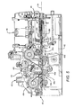
- FIG. 2 shows in block diagram form and FIGS. 3-5 show in greater detail, a specific, exemplary embodiment of a card processing system 40 in accordance with the present invention.
- the system 40 comprises a card printer for printing on cards 10 such as that shown in FIG. 1.
- the card printer 40 may comprise a thermal transfer card printer of the kind typically used to print information in the form of text, graphics, photographs, and so forth, on plastic cards such as I.D. cards, driver's licenses, and the like, using a thermal printhead cooperating with a thermal transfer or dye sublimation ribbon carried by a disposable ribbon cartridge.
- the card feeder 44 includes a card feeder body 60 defining a card supply compartment 62 for holding a card stack 64 comprising a plurality of cards 10a, 10b, 10c, and so forth, to be processed.
- the compartment 62 contains means 66 for biasing the card stack 64 toward a card feed mechanism 68 that removes the cards 10a, et seq., in succession from the card supply compartment 62 and prevents or inhibits the removal of more than one card at a time from the stack.
- the card feed mechanism 68 operates independently of card thickness, the feed mechanism being thus capable of feeding cards of different thicknesses without adjustment.
- the card supply compartment 62 has a generally rectangular configuration and is defined by opposed, parallel side walls 70 and 72, a fixed front end wall 74 and a bottom wall 76 of the feeder body 60.
- the card supply compartment 62 is open at the top for receiving a supply of cards to be fed through a front, transverse, slot-like discharge opening 78 ( FIGS. 6, 10 and 14 ) of fixed size defined by a lower edge 80 of the front wall 74 and a front edge 82 of the bottom wall 76.
- the cards are advanced in succession through the opening 78 by means of the card feed mechanism 68 in a generally downward direction (as indicated by the arrow) along the generally vertical, first feed path 52, toward the rotator 46.
- the pusher plate 90 is mounted for smooth, stable, jam-free translation within the compartment 62 by means of a spring-loaded mechanism 92 seen in FIGS. 6, 8 and 9.
- the mechanism 92 comprises two pairs of meshed pinions 94, 96 and 98, 100 secured to the ends of a pair of parallel, upper and lower transverse shafts 102 and 104 mounted on a rear surface 106 of the pusher plate 90. More specifically, the upper transverse shaft 102 is journaled for rotation in vertical legs 108 and 110 defined by the pusher plate 90 at opposite ends thereof.
- the lower transverse shaft 104 is journaled for rotation in a central bearing block 112 on the rear surface 106 of the pusher plate 90.
- the pinions 94 and 96 mesh with spaced-apart, parallel, horizontal racks 114 and 116 mounted on or made integral with the side wall 70 of the feeder body.
- the pinions 98 and 100 mesh with spaced-apart, parallel, horizontal racks 118 and 120 on the side wall 72.
- a pair of torsion springs 122 and 124 wound about the shaft 104 and anchored at their inner ends to the central bearing block 112 and at their outer ends to the respective pinions 96 and 100, provide the resilient bias that urges the pusher plate 90 against the rear of the card stack.
- the torsion springs 122 and 124 are preloaded, that is, they are wound and mounted so as to be under an initial torsional load.
- the card feed mechanism 68 includes friction drive surfaces, preferably in the form of three rollers 130, 132 and 134 at the front of the card supply compartment 62.
- the roller 130 comprises a first or primary feed roller that is mounted on a transverse shaft 136 journaled for rotation in the side walls 70 and 72 of the card feeder body at a fixed position above the bottom wall 76.
- the first feed roller 130 is centered transversely and its drive surface projects slightly into the card supply compartment 62 so that the leading or first card 10a ( FIGS. 6, 7, and 14) in a stack of cards loaded into the compartment frictionally engages the first feed roller 130 in response to the resilient bias exerted by the pusher plate 90.
- the tertiary roller 134 is mounted on the inner end of a shaft 162 supported by a floating plate 164 in turn carried by a pair of fixed guide pins 166 and 168 projecting from the lower surface of the bottom wall 76 and extending through oversize slots 170 and 172 in the plate 164.
- a tension spring 174 anchored between a post 176 near the rear of the plate 164 and a fixed post 178 projecting from the bottom wall resiliently biases the plate 164 to urge the tertiary roller 134 toward the secondary roller 132 and into contact therewith in the absence of a card.
- the tertiary roller shaft 162 has an outer end 180 projecting from the feeder body side wall 70 through an oversize opening (not shown) permitting floating movement of the plate 164 in response to the presence of cards of different thicknesses between the secondary and tertiary rollers 132 and 134.
- a hub 181 secured to a pivotable plate 182 defining spaced-apart abutment surfaces 183 and 184 positioned to engage a fixed post 185 mounted on the feeder sidewall 70.
- the plate 182 is retained on the shaft 162 by a snap ring 186.
- the shaft 162 and the tertiary roller 134 carried thereby are thus able to pivot within the limits imposed by the spacing between the abutment surfaces 183 and 184.
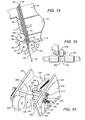
- the card feed mechanism 68 prevents the removal of more than one card at a time from the card stack 64. More specifically, when a first, individual card 10a passes between the secondary and tertiary rollers 132 and 134 (FIG. 14), a fluctuating pinch is created on the card depending upon the thickness of the card through the spring loaded, floating plate 164 and the tertiary roller 134 carried thereby. With reference to FIG. 14, assume now that a second card 10b, clinging to the first card 10a because of a static charge, for example, is erroneously withdrawn from the stack along with the first card 10a.
- the torsion spring 187 mounted on the outer end 180 of the tertiary roller shaft 162 winds up in response to the amount of friction between the first and second cards 10a and 10b versus the amount of friction between the second card 10b and the tertiary roller 134. Because the friction between the tertiary roller 134 and the second card 10b is greater than the friction between the first and second cards 10a and 10b, the torsion spring 187 is wound up (to the extent permitted by the limit imposed when the abutment surface 183 engages the post 185) causing the spring 187, when its stored energy is released, to force the second card 10b back toward the card stack 64 until the first card 10a has exited the zone 160 between the secondary and tertiary rollers.
- the primary and secondary rollers 130 and 132 are preferably made of the same material, for example, silicone.
- the tertiary roller 134 is preferably made of the same material as the primary and secondary rollers but alternatively may be constructed of a different material such as ethylene propylene diene monomer (EPDM).
- EPDM ethylene propylene diene monomer
- the primary and secondary rollers 130 and 132 preferably have the same outer diameter.
- the rollers 130 and 132 may have different diameters in which case they are driven at such angular rates that they have the same peripheral velocity.
- the secondary and tertiary rollers 132 and 134 are mounted so that a leading card fed by the primary roller 130 is engaged by both the secondary and tertiary rollers.
- the maximum spacing between the opposed outer surfaces of the secondary and tertiary rollers might ideally be set at .007 inch.
- cumulative tolerances in the various parts of the feeder mechanism may preclude precisely setting that spacing. Accordingly, FIG. 15 shows an alternative embodiment in which the need for close tolerances between the secondary and tertiary rollers is avoided. More specifically, FIG.
- FIG. 15 illustrates a secondary roller 500 having a stepped diameter with a smaller diameter portion or circumferential groove 502 in the central part of the roller opposite a tertiary roller 504.
- the tertiary roller 504 has an outer card-engaging surface 506 that projects slightly into the groove 502 in the secondary roller 500 to introduce a small degree of overlap between the rollers. This arrangement, which does not depend on tight tolerances, always assures contact between a leading card fed from the card feeder and both of the rollers 500 and 504; the slight deflection of the card introduced by this offset arrangement does not affect the operation of the feed mechanism.
- the tertiary roller 202 is carried by a shaft 206 journaled for rotation in a floating plate 208 resiliently biased by a tension spring 210 to urge the tertiary roller 202 toward the secondary roller 200 and into contact therewith when no card is present and into engagement with the back face of a card advanced along the feed path 195.
- An outer end 214 of the tertiary roller shaft 206 projects through an oversize opening 216 in a sidewall 218 of the card feeder body.
- the opening 216 is larger than the diameter of the tertiary roller shaft 206 to allow the floating plate 208 to be displaced in response to the presence of cards of various thicknesses transported along the feed path 195 between the secondary and tertiary rollers.
- Fixed to the outer, projecting end of the tertiary roller shaft 206 is a timing belt sprocket 220.
- a shaft 222 that supports and drives the primary card feed roller 198 has an outer end 224 projecting from the side wall 218.
- a collar 226 secured to the shaft so that the collar rotates with the shaft.
- a clutch 228 including a fiber washer 230 that functions as a clutch disk.
- Adjacent to the fiber washer 230 is a sprocket 232 that is free to rotate on the primary feed roller shaft 222.
- a compression spring 236 Disposed between a retainer washer 234 on the outer extremity of the shaft 222 and the outer face of the sprocket 232 is a compression spring 236 that urges the sprocket 232 into frictional engagement with the fiber washer 230.
- a timing belt 238 couples the sprocket 232 on the shaft 222 and the sprocket 220 secured to the tertiary roller shaft 206. It will be seen that the single stepper motor 204 drives all three rollers 198, 200 and 202 in the same rotational direction.
- the tertiary roller When no card is present between the secondary and tertiary rollers 200 and 202, the tertiary roller is driven by the secondary roller in the opposite rotational direction thereto, the friction between these rollers being sufficient to effect such drive and to cause the clutch 228, which tends to drive the tertiary roller in the same direction as the primary and secondary rollers, to slip.
- the stepper motor 204 acting through the clutch 228, at all times tends to rotate the tertiary roller 202 in the same direction as the primary and secondary rollers 198 and 200. This tendency is overcome, and the clutch 228 slips, when no card or one card is present in the pinch zone between the secondary and tertiary rollers. It is only when a second card is erroneously withdrawn from the card stack along with a first card, that the tertiary roller rotates in a direction forcing the second card back into the card stack.
- FIGS. 18-21 there are shown alternative embodiments of the card feed mechanisms 68 and 196 described above for feeding cards 10a, 10b, and so forth, one at a time along a generally vertical first feed path 250.
- the embodiment of FIG. 18 comprises a card feed mechanism 252 including a primary frictional drive surface in the form of an endless belt 254 trained about rotatable drums 256 and 258, and a secondary frictional drive surface in the form of a roller 260.
- the embodiment of FIG. 19 comprises a card feed mechanism 262 including a primary frictional drive surface in the form of a roller 264 and a secondary frictional drive surface in the form of an endless belt 266.
- FIG. 18 comprises a card feed mechanism 252 including a primary frictional drive surface in the form of an endless belt 254 trained about rotatable drums 256 and 258, and a secondary frictional drive surface in the form of a roller 260.
- the embodiment of FIG. 19 comprises a card feed mechanism 262 including a primary frictional drive surface in the form
- a card feed mechanism 268 comprising primary and secondary frictional drive surfaces defined by endless belts 270 and 272, while in the embodiment of FIG. 21, a card feed mechanism 274 combines both the primary and secondary frictional drive surfaces into a single endless belt 276.
- the card re-director or rotator 46 is mounted on a frame or base 300 for rotation about a central, horizontal axis 302.
- the rotator comprises a card receiving, holding and ejecting subassembly 304 comprising a pair of parallel, spaced-apart plates 306 and 308 defining between them a card throat 310 having an elongated card input opening or slot 312 extending parallel with the central axis 302.
- the card throat 310 receives each of the cards 10 fed from the card feeder 44 and holds each card during rotation thereof.
- the card 10 is held against stops (not shown) within the card throat 310 by gravity.
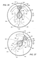
- the plate subassembly 304 is supported at one end by a disk 314 and at the other end by a stub shaft 316 journaled for rotation in an aperture 318 in an end wall 320 of the base 300 (FIG. 30).
- the stub shaft 316 projects from the end wall 320 and carries a large, rotator drive gear 322 that can rotate relative to the stub shaft 316.
- the disk 314 and the gear 322 lie in vertical, parallel planes and are centered on, and rotatable about, the central axis 302.
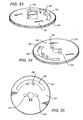
- the disk 314 defines an elongated, transverse card discharge opening or slot 324 extending along a diameter of the disk in alignment with the card throat 310. As will be explained, cards are transported from the throat through the rotator discharge slot 324 for loading into the card print mechanism 48.
- the plate subassembly 304 is rotatably supported at its one end by the disk 314 which has a periphery 326 engaging three equiangularly spaced, flanged disk support wheels 328, 330 and 332 mounted for rotation on a side member 334 of the rotator base 300.
- the end gear 322 is in mesh with a smaller gear 336 in turn driven by the output shaft of a computer controlled stepper motor 337 (FIG. 27).
- An optical sensor 338 on the rotator base 300 operatively associated with a photointerrupter 340 on the disk 314 provides electrical output signals responsive to the angular position of the card rotator.
- the output signals generated by the optical sensor 338 are coupled to a printer controller along with output signals generated by card edge and other detectors (not shown) for coordinating the operation of the various elements of the printer, in a manner well known in the art.
- the rotator drive gear 322 has a central sleeve 380 that receives the stub shaft 316.
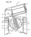
- the gear 322 further includes an arcuate slot 382 concentric with the axis of rotation 302 (FIG. 22). Projecting outwardly from an outer face 384 of the gear adjacent the inner edge of the arcuate slot 382 at the midpoint thereof is a lug 386.
- the lug 386 is in alignment with a corresponding lug 388 projecting from the gear end of the throat-defining plate subassembly 304.
- the pivotable arms 350 and 362 include outer ends 396 and 398, respectively, positioned to be engaged by the cams 392 and 394, respectively, so that relative rotational motion between the gear 322 and the subassembly 304 will cause the arms 350 and 362 (and hence the rollers 356 and 368) to be moved apart against the bias of the springs 374 and 376 or toward each other under the bias of the springs.
- the central sleeve 380 on the gear 322 carries a torsion spring 400 having crossed ends 402 and 404 engaging the sides of the aligned lugs 386 and 388.
- the lugs are thereby held in alignment under the torsional bias of the torsion spring 400. Accordingly, rotation of the gear 322 will cause the throat-defining plate subassembly 304 to follow, that is, the gear 322 and the subassembly 304 will rotate in unison.
- the cams 392 and 394 on the gear 322 are disposed to lift the arms 350 and 362 to keep the rollers 356 and 368 apart.
- the card re-director or rotator 46 is rotated to an initial position shown in FIGS. 22-24, 27-29, 36 and 40, in which the card throat 310 is in alignment with the first feed path 52. In this position, the throat 310 is disposed to receive a card 10 withdrawn from the card stack 64 and advanced by the card feed mechanism 68 along the first feed path 52.
- the feeder compartment 62 is slightly tipped with the bottom wall 76 of the feeder sloping down toward the front wall 74. This orientation both assists the user's manual loading of the feeder compartment 62 and adds gravity bias to help urge the card stack 64 toward the front wall 74 of the compartment without appreciably increasing the overall height of the printer.
- the angle is preferably that at which sliding of the card stack 64 impends, for example, about 15° for a given angular coefficient of friction in accordance with one practical embodiment. Although such a tipped orientation is preferred, it will be evident that the compartment 62 may be horizontal so that the orientations of both the cards in the stack and the first feed path 52 are vertical.
- the card is driven back into the card throat 310 along the horizontal path 54 in a reverse direction and back into the rotator 46.
- the rotator rotates in reverse, moving 180° to flip or invert the card after which the card is driven out of the rotator and printed on the other side.
- the drive pinion 414 will engage the roller drive gear 360 or 372 on the other arm 350 or 362.
- the card cleaning station 48a comprises the stacked combination of primary "sticky” roller 604 and a secondary “sticky” roller 606.
- the rollers 604 and 606 are normally resiliently biased downwardly toward the card path 54 but may be selectively moved upwardly away from the path 54 by a cam mechanism (not shown).
- a card is driven out of the throat 310 of the card re-director or rotator 46 along the path 54 (to the left as seen in FIG. 5) by means of the drive rollers 356 and 368.
- the card is further driven to the left by the "half" roller 600 until the card clears the cleaning station 48a and the trailing edge of the card is at the roller 600.
- the cleaning rollers 604 and 606 as well as the rotator drive rollers 356 and 368 are then cammed away from the card path 54.
- the card is driven back by the roller 600 towards the throat 310 with the magnetic strip moving past the magnetic head 602. It is during this reverse pass that the card strip is magnetically encoded by the head 602. It will be appreciated that with the rollers 356, 368, 604 and 606 clear of the card path 54 during this encoding operation, the card will not strike any structure that might otherwise cause "jitter" and a possible failure of the encoding process.
- the card rotator 46 is constructed and the card input and discharge slots 312 and 324 are so positioned that a card is oriented for rotation about its short edges to conserve space, but oriented for printing in a direction parallel with its long edges. It would be possible, of course, to eliminate the transverse discharge slot 324 and feed cards both into and out of the slot 312 with the print mechanism appropriately positioned to receive the cards from the slot 312. This means that the application of information to the card face(s) would take place as each card is transported in the direction parallel with the short edges thereof.
Landscapes
- Engineering & Computer Science (AREA)
- Mechanical Engineering (AREA)
- Sheets, Magazines, And Separation Thereof (AREA)
- Handling Of Cut Paper (AREA)
- Feeding Of Articles By Means Other Than Belts Or Rollers (AREA)
- Delivering By Means Of Belts And Rollers (AREA)
Applications Claiming Priority (3)
| Application Number | Priority Date | Filing Date | Title |
|---|---|---|---|
| US53662104P | 2004-01-14 | 2004-01-14 | |
| US10/852,769 US7328897B2 (en) | 2003-10-20 | 2004-05-21 | Card printer and method of printing on cards |
| EP05705447A EP1711344A2 (fr) | 2004-01-14 | 2005-01-11 | Imprimante de cartes et procede d'impression de cartes |
Related Parent Applications (2)
| Application Number | Title | Priority Date | Filing Date |
|---|---|---|---|
| EP05705447A Division EP1711344A2 (fr) | 2004-01-14 | 2005-01-11 | Imprimante de cartes et procede d'impression de cartes |
| EP05705447.0 Division | 2005-01-11 |
Publications (4)
| Publication Number | Publication Date |
|---|---|
| EP1764228A2 true EP1764228A2 (fr) | 2007-03-21 |
| EP1764228A3 EP1764228A3 (fr) | 2007-07-11 |
| EP1764228A8 EP1764228A8 (fr) | 2010-06-02 |
| EP1764228B1 EP1764228B1 (fr) | 2011-12-14 |
Family
ID=34811326
Family Applications (2)
| Application Number | Title | Priority Date | Filing Date |
|---|---|---|---|
| EP05705447A Withdrawn EP1711344A2 (fr) | 2004-01-14 | 2005-01-11 | Imprimante de cartes et procede d'impression de cartes |
| EP06125566A Expired - Lifetime EP1764228B1 (fr) | 2004-01-14 | 2005-01-11 | Imprimante de cartes et procédé d'impression de cartes |
Family Applications Before (1)
| Application Number | Title | Priority Date | Filing Date |
|---|---|---|---|
| EP05705447A Withdrawn EP1711344A2 (fr) | 2004-01-14 | 2005-01-11 | Imprimante de cartes et procede d'impression de cartes |
Country Status (4)
| Country | Link |
|---|---|
| US (2) | US7328897B2 (fr) |
| EP (2) | EP1711344A2 (fr) |
| TW (1) | TWI265137B (fr) |
| WO (1) | WO2005070687A2 (fr) |
Families Citing this family (34)
| Publication number | Priority date | Publication date | Assignee | Title |
|---|---|---|---|---|
| US7878505B2 (en) | 2003-08-19 | 2011-02-01 | Hid Global Corporation | Credential substrate rotator and processing module |
| US7934881B2 (en) * | 2003-10-20 | 2011-05-03 | Zih Corp. | Replaceable ribbon supply and substrate cleaning apparatus |
| US7328897B2 (en) * | 2003-10-20 | 2008-02-12 | Zih Corp. | Card printer and method of printing on cards |
| JP4545575B2 (ja) * | 2004-12-14 | 2010-09-15 | ローレル機械株式会社 | 紙幣取込装置 |
| US7434728B2 (en) * | 2005-02-04 | 2008-10-14 | Datacard Corporation | Desktop card processor |
| US8429787B2 (en) * | 2005-07-27 | 2013-04-30 | Zih Corp. | Dual use cleaning apparatus and method |
| TWI274674B (en) * | 2006-02-10 | 2007-03-01 | Hi Touch Imaging Tech Co Ltd | Card printer having a cam to push a magnetic head bearer to move toward a direction away from an encoder roller |
| US8721205B2 (en) * | 2007-10-10 | 2014-05-13 | Hid Global Corporation | Credential manufacturing device having an auxiliary card input |
| US8418348B2 (en) * | 2008-07-22 | 2013-04-16 | Shimadzu Corporation | Manufacturing method of scattered radiation removing grid |
| WO2011035114A1 (fr) | 2009-09-18 | 2011-03-24 | Hid Global Corporation | Rotateur de substrat de carte |
| EP2520436B1 (fr) * | 2009-12-28 | 2020-02-26 | Toppan Printing Co., Ltd. | Dispositif d'impression |
| EP2528672A4 (fr) | 2010-01-29 | 2013-11-06 | Tung Kwong Lai | Systèmes et procédés pour faciliter participation à jeux de cartes |
| US8702328B2 (en) * | 2010-03-05 | 2014-04-22 | Datacard Corporation | Desktop card printer |
| RO126347B1 (ro) * | 2010-06-24 | 2017-09-29 | Mb Telecom Ltd S.R.L. | Metodă şi sistem de securizare a utilizării cartelelor cu bandă magnetică |
| JP5931211B2 (ja) * | 2012-10-25 | 2016-06-08 | 京セラドキュメントソリューションズ株式会社 | 給紙カセット、用紙給送装置及び画像形成装置 |
| DE102014004353A1 (de) | 2014-03-27 | 2015-10-01 | Murrplastik Systemtechnik Gmbh | Vorrichtung zur Beschriftung von Kennzeichnungseinheiten |
| DE102014012055A1 (de) * | 2014-08-18 | 2016-02-18 | Murrplastik Systemtechnik Gmbh | Vorrichtung zur Beschriftung von Kennzeichnungseinheiten |
| KR102572736B1 (ko) * | 2015-04-09 | 2023-08-29 | 인트러스트 코포레이션 | 모듈식 인쇄 엔진 및 모듈식 인쇄 엔진 구성요소 |
| US9962951B2 (en) * | 2015-10-16 | 2018-05-08 | Entrust Datacard Corporation | Front and back printing on security document substrates |
| CN111907220B (zh) * | 2016-01-08 | 2022-09-20 | 恩图鲁斯特咨询卡有限公司 | 具有卡片返回路径的卡片印刷机构 |
| CN108688338B (zh) * | 2017-04-11 | 2023-10-20 | 广州正和电子科技有限公司 | 一种打印卡片的打印机装置 |
| USD854079S1 (en) | 2017-07-07 | 2019-07-16 | Zebra Technologies Corporation | Media processing device |
| US20190010015A1 (en) * | 2017-07-07 | 2019-01-10 | Zih Corp. | Media unit redirector assembly for media processing devices |
| US10843491B2 (en) | 2017-07-07 | 2020-11-24 | Zebra Technologies Corporation | Media unit leveling assembly for media processing devices |
| US10189660B1 (en) | 2017-07-07 | 2019-01-29 | Zih Corp. | Auxiliary media unit transporter for media processing devices |
| US10639914B2 (en) | 2017-07-07 | 2020-05-05 | Zih Corp. | Rejected media unit storage for media processing devices |
| US10377591B2 (en) | 2017-07-07 | 2019-08-13 | Zebra Technologies Corporation | Input handling for media processing devices |
| CN107239804B (zh) * | 2017-07-14 | 2023-11-07 | 杭州通昊科技有限公司 | 一种自动收发卡机 |
| US10633208B2 (en) | 2017-11-08 | 2020-04-28 | Zebra Technologies Corporation | Output hopper for media processing devices |
| US11285750B2 (en) * | 2018-09-20 | 2022-03-29 | Entrust Corporation | Collapsible ribbon supply cartridge |
| CN111186218B (zh) * | 2018-11-15 | 2025-06-06 | 苏州苏大维格科技集团股份有限公司 | 一种打印机台 |
| US11034536B2 (en) | 2019-02-01 | 2021-06-15 | Assa Abloy Ab | Card flipper |
| CN110744931B (zh) * | 2019-10-15 | 2024-08-06 | 江门市得实计算机外部设备有限公司 | 一种卡片翻转机构及打印机 |
| CN115136214B (zh) * | 2020-02-21 | 2024-02-23 | 富士通先端科技株式会社 | 纸张类处理装置 |
Citations (1)
| Publication number | Priority date | Publication date | Assignee | Title |
|---|---|---|---|---|
| US6587135B1 (en) | 1998-10-16 | 2003-07-01 | Jvc Victor Company Of Japan, Ltd. | Card recording apparatus |
Family Cites Families (40)
| Publication number | Priority date | Publication date | Assignee | Title |
|---|---|---|---|---|
| US3737884A (en) * | 1971-06-28 | 1973-06-05 | J Wallace | Magnetic card reader-encoder |
| US4519600A (en) | 1983-09-21 | 1985-05-28 | Data Card Corporation | Card feeding, transfer and output apparatus for an automatic embossing system |
| US5037216A (en) | 1988-09-23 | 1991-08-06 | Datacard Corporation | System and method for producing data bearing cards |
| WO1991000183A1 (fr) | 1989-07-04 | 1991-01-10 | Toppan Insatsu Kabushiki Kaisha | Appareil servant a preparer des cartes d'enregistrement de donnees |
| US5486057A (en) * | 1992-05-06 | 1996-01-23 | Eltron International, Inc. | Multicolor printer system having multiple print heads |
| US5421261A (en) | 1993-04-27 | 1995-06-06 | Gerber Scientific Products, Inc. | Printing apparatus having web-cleaning members for removing particles affecting print quality |
| JPH07164707A (ja) | 1993-12-13 | 1995-06-27 | Brother Ind Ltd | 印字装置におけるキャリッジの走行装置 |
| US5600362A (en) * | 1994-04-15 | 1997-02-04 | Gemplus Card International | Automatic system for front-and-back printing of cards in black and white and in color, by reversing the card |
| JPH08127157A (ja) * | 1994-10-28 | 1996-05-21 | Nisca Corp | 両面プリンタ及び両面印刷方法 |
| US5503382A (en) * | 1995-02-13 | 1996-04-02 | Xerox Corporation | Misfeed detector for multi-tray and intermediate tray sheet feeders |
| US5667316A (en) | 1995-03-13 | 1997-09-16 | Atlantek Inc. | Card printing apparatus |
| US5966160A (en) * | 1995-03-13 | 1999-10-12 | Atlantek , Inc. | In-line flip station for a card printing apparatus |
| US5673076A (en) * | 1995-03-13 | 1997-09-30 | Atlantek Inc. | Card printing and laminating apparatus |
| US5637174A (en) * | 1995-04-10 | 1997-06-10 | Atlantek, Inc. | Apparatus for automated one-up printing and production of an identification card |
| DE19644306C2 (de) * | 1996-10-24 | 1999-04-08 | Kunz Gmbh | Vorrichtung zum Personalisieren von Identifikationskarten |
| JP3366791B2 (ja) * | 1995-11-09 | 2003-01-14 | ニスカ株式会社 | 情報記録装置 |
| JP3309943B2 (ja) | 1995-11-13 | 2002-07-29 | ニスカ株式会社 | 記録装置 |
| US5871209A (en) * | 1996-03-01 | 1999-02-16 | Currency Systems International, Inc. | Cassette based document handling system |
| FI101954B1 (fi) * | 1996-09-27 | 1998-09-30 | Jomet Oy | Menetelmä ja laitteisto litteiden esineiden pakkaamiseksi |
| US5806843A (en) * | 1997-01-13 | 1998-09-15 | Xerox Corporation | Multi tray and buffer tray misfeed detector with voltage response adjustment |
| US5836580A (en) * | 1997-01-13 | 1998-11-17 | Xerox Corporation | Single tray and multi tray misfeed detector with voltage response adjustment |
| US5769407A (en) * | 1997-01-13 | 1998-06-23 | Xerox Corporation | Misfeed detector with voltage response adjustment |
| JPH11309967A (ja) * | 1998-04-27 | 1999-11-09 | Sony Corp | カード印刷装置 |
| US6408151B1 (en) | 1999-05-11 | 2002-06-18 | Zih Corp. | Card cleaning device |
| US6285845B1 (en) | 1999-05-11 | 2001-09-04 | Zih Corp. | Card cleaning device and method of use |
| JP3330355B2 (ja) * | 1999-08-31 | 2002-09-30 | ニスカ株式会社 | カード類の記録装置 |
| JP3976477B2 (ja) * | 2000-06-16 | 2007-09-19 | 日本ビクター株式会社 | 熱転写記録装置 |
| US6582141B2 (en) | 2000-06-27 | 2003-06-24 | Fargo Electronics, Inc. | Card cleaning roller assembly |
| US6679489B2 (en) * | 2000-06-30 | 2004-01-20 | First Data Resources, Inc. | Multiple insert delivery systems and methods |
| US6669186B2 (en) * | 2000-06-30 | 2003-12-30 | First Data Corporation | Multiple insert delivery systems and methods |
| JP3667617B2 (ja) * | 2000-09-28 | 2005-07-06 | ニスカ株式会社 | カード処理装置 |
| GB0024640D0 (en) | 2000-10-07 | 2000-11-22 | Ksm Internat Ltd | Substrate cleaning |
| US6786482B2 (en) * | 2001-02-01 | 2004-09-07 | Hallmark Cards Incorporated | Material handler apparatus |
| US6938896B2 (en) * | 2001-02-22 | 2005-09-06 | Asahi Seiko Co., Ltd | Automatic card dispensing unit with display capability |
| US6554512B2 (en) | 2001-04-26 | 2003-04-29 | Zih Corp. | Printer for printing deformable flat supports and its loader |
| US6985266B2 (en) * | 2001-04-26 | 2006-01-10 | Zih Corp. | Printer of a new type |
| US6942212B2 (en) * | 2002-04-26 | 2005-09-13 | Hewlett-Packard Development Company, L.P. | Mechanical media top level elevator |
| US7063013B2 (en) * | 2003-09-05 | 2006-06-20 | Zebra Atlantek, Inc. | Card-flipping device for use in card printers |
| US7328897B2 (en) * | 2003-10-20 | 2008-02-12 | Zih Corp. | Card printer and method of printing on cards |
| DE102004004893B3 (de) * | 2004-01-30 | 2005-04-07 | Pitney Bowes Deutschland Gmbh | Kuvertwendestation |
-
2004
- 2004-05-21 US US10/852,769 patent/US7328897B2/en not_active Expired - Lifetime
-
2005
- 2005-01-11 TW TW094100716A patent/TWI265137B/zh not_active IP Right Cessation
- 2005-01-11 WO PCT/US2005/000795 patent/WO2005070687A2/fr not_active Ceased
- 2005-01-11 EP EP05705447A patent/EP1711344A2/fr not_active Withdrawn
- 2005-01-11 EP EP06125566A patent/EP1764228B1/fr not_active Expired - Lifetime
-
2007
- 2007-12-13 US US11/955,890 patent/US20080089730A1/en not_active Abandoned
Patent Citations (1)
| Publication number | Priority date | Publication date | Assignee | Title |
|---|---|---|---|---|
| US6587135B1 (en) | 1998-10-16 | 2003-07-01 | Jvc Victor Company Of Japan, Ltd. | Card recording apparatus |
Also Published As
| Publication number | Publication date |
|---|---|
| EP1764228B1 (fr) | 2011-12-14 |
| US20080089730A1 (en) | 2008-04-17 |
| US20050082738A1 (en) | 2005-04-21 |
| EP1764228A8 (fr) | 2010-06-02 |
| WO2005070687A3 (fr) | 2006-01-26 |
| WO2005070687A2 (fr) | 2005-08-04 |
| EP1764228A3 (fr) | 2007-07-11 |
| US7328897B2 (en) | 2008-02-12 |
| TWI265137B (en) | 2006-11-01 |
| EP1711344A2 (fr) | 2006-10-18 |
| TW200526500A (en) | 2005-08-16 |
Similar Documents
| Publication | Publication Date | Title |
|---|---|---|
| EP1764228B1 (fr) | Imprimante de cartes et procédé d'impression de cartes | |
| US6296405B1 (en) | Duplex check printer using a print mechanism pivoted between document paths | |
| CN101254713B (zh) | 图像记录设备 | |
| EP0274989A2 (fr) | Imprimante pour double-face | |
| EP0054708B1 (fr) | Dispositif pour traiter des documents | |
| EP0398515A2 (fr) | Mécanisme de transport de livres de comptes pour l'imprimante d'un livre de comptes | |
| CN1930003B (zh) | 卡片印刷机以及在卡片上印刷的方法 | |
| JPH08282897A (ja) | 自動原稿送り装置 | |
| JPH0336155A (ja) | 券格納装置 | |
| US4228953A (en) | Dual belt drive | |
| EP1663658B1 (fr) | Dispositif d'impression | |
| JP4930103B2 (ja) | 媒体収納装置 | |
| JP3640229B2 (ja) | 板状被搬送体の整列収納装置 | |
| JP2004043095A (ja) | 記録装置および被記録材搬送用トレイ | |
| JPH057304B2 (fr) | ||
| JP2572780Y2 (ja) | 原稿搬送装置 | |
| JPH0867376A (ja) | 紙葉類搬送装置に於ける幅寄せ機構 | |
| JPH0940231A (ja) | 媒体幅寄せ装置 | |
| JPH0627422Y2 (ja) | 自動給紙装置 | |
| JP2004050773A (ja) | 媒体処理装置 | |
| JP2001294336A (ja) | 原稿自動給紙装置 | |
| JPH0524693A (ja) | シート送り装置 | |
| JPH0536579U (ja) | 積層カードの送り出し装置 | |
| JPH0336157A (ja) | 券格納装置 | |
| JP2001220034A (ja) | 給紙装置 |
Legal Events
| Date | Code | Title | Description |
|---|---|---|---|
| PUAI | Public reference made under article 153(3) epc to a published international application that has entered the european phase |
Free format text: ORIGINAL CODE: 0009012 |
|
| 17P | Request for examination filed |
Effective date: 20061207 |
|
| AC | Divisional application: reference to earlier application |
Ref document number: 1711344 Country of ref document: EP Kind code of ref document: P |
|
| AK | Designated contracting states |
Kind code of ref document: A2 Designated state(s): AT BE BG CH CY CZ DE DK EE ES FI FR GB GR HU IE IS IT LI LT LU LV MC NL PL PT RO SE SI SK TR |
|
| AX | Request for extension of the european patent |
Extension state: AL BA HR MK YU |
|
| PUAL | Search report despatched |
Free format text: ORIGINAL CODE: 0009013 |
|
| AK | Designated contracting states |
Kind code of ref document: A3 Designated state(s): AT BE BG CH CY CZ DE DK EE ES FI FR GB GR HU IE IS IT LI LT LU LV MC NL PL PT RO SE SI SK TR |
|
| AX | Request for extension of the european patent |
Extension state: AL BA HR MK YU |
|
| AKX | Designation fees paid |
Designated state(s): AT BE BG CH CY CZ DE DK EE ES FI FR GB GR HU IE IS IT LI LT LU LV MC NL PL PT RO SE SI SK TR |
|
| 17Q | First examination report despatched |
Effective date: 20080416 |
|
| RBV | Designated contracting states (corrected) |
Designated state(s): AT BE BG CH CY CZ DE DK EE ES FI FR GB GR HU IE IS IT LI LT LU MC NL PL PT RO SE SI SK TR |
|
| GRAP | Despatch of communication of intention to grant a patent |
Free format text: ORIGINAL CODE: EPIDOSNIGR1 |
|
| GRAS | Grant fee paid |
Free format text: ORIGINAL CODE: EPIDOSNIGR3 |
|
| GRAA | (expected) grant |
Free format text: ORIGINAL CODE: 0009210 |
|
| AC | Divisional application: reference to earlier application |
Ref document number: 1711344 Country of ref document: EP Kind code of ref document: P |
|
| AK | Designated contracting states |
Kind code of ref document: B1 Designated state(s): AT BE BG CH CY CZ DE DK EE ES FI FR GB GR HU IE IS IT LI LT LU MC NL PL PT RO SE SI SK TR |
|
| REG | Reference to a national code |
Ref country code: GB Ref legal event code: FG4D |
|
| REG | Reference to a national code |
Ref country code: CH Ref legal event code: EP |
|
| REG | Reference to a national code |
Ref country code: IE Ref legal event code: FG4D |
|
| REG | Reference to a national code |
Ref country code: DE Ref legal event code: R096 Ref document number: 602005031712 Country of ref document: DE Effective date: 20120308 |
|
| REG | Reference to a national code |
Ref country code: NL Ref legal event code: VDEP Effective date: 20111214 |
|
| PG25 | Lapsed in a contracting state [announced via postgrant information from national office to epo] |
Ref country code: LT Free format text: LAPSE BECAUSE OF FAILURE TO SUBMIT A TRANSLATION OF THE DESCRIPTION OR TO PAY THE FEE WITHIN THE PRESCRIBED TIME-LIMIT Effective date: 20111214 |
|
| LTIE | Lt: invalidation of european patent or patent extension |
Effective date: 20111214 |
|
| PG25 | Lapsed in a contracting state [announced via postgrant information from national office to epo] |
Ref country code: SE Free format text: LAPSE BECAUSE OF FAILURE TO SUBMIT A TRANSLATION OF THE DESCRIPTION OR TO PAY THE FEE WITHIN THE PRESCRIBED TIME-LIMIT Effective date: 20111214 Ref country code: NL Free format text: LAPSE BECAUSE OF FAILURE TO SUBMIT A TRANSLATION OF THE DESCRIPTION OR TO PAY THE FEE WITHIN THE PRESCRIBED TIME-LIMIT Effective date: 20111214 Ref country code: SI Free format text: LAPSE BECAUSE OF FAILURE TO SUBMIT A TRANSLATION OF THE DESCRIPTION OR TO PAY THE FEE WITHIN THE PRESCRIBED TIME-LIMIT Effective date: 20111214 Ref country code: GR Free format text: LAPSE BECAUSE OF FAILURE TO SUBMIT A TRANSLATION OF THE DESCRIPTION OR TO PAY THE FEE WITHIN THE PRESCRIBED TIME-LIMIT Effective date: 20120315 |
|
| PG25 | Lapsed in a contracting state [announced via postgrant information from national office to epo] |
Ref country code: CY Free format text: LAPSE BECAUSE OF FAILURE TO SUBMIT A TRANSLATION OF THE DESCRIPTION OR TO PAY THE FEE WITHIN THE PRESCRIBED TIME-LIMIT Effective date: 20111214 Ref country code: BE Free format text: LAPSE BECAUSE OF FAILURE TO SUBMIT A TRANSLATION OF THE DESCRIPTION OR TO PAY THE FEE WITHIN THE PRESCRIBED TIME-LIMIT Effective date: 20111214 |
|
| PG25 | Lapsed in a contracting state [announced via postgrant information from national office to epo] |
Ref country code: BG Free format text: LAPSE BECAUSE OF FAILURE TO SUBMIT A TRANSLATION OF THE DESCRIPTION OR TO PAY THE FEE WITHIN THE PRESCRIBED TIME-LIMIT Effective date: 20120314 Ref country code: IS Free format text: LAPSE BECAUSE OF FAILURE TO SUBMIT A TRANSLATION OF THE DESCRIPTION OR TO PAY THE FEE WITHIN THE PRESCRIBED TIME-LIMIT Effective date: 20120414 Ref country code: CZ Free format text: LAPSE BECAUSE OF FAILURE TO SUBMIT A TRANSLATION OF THE DESCRIPTION OR TO PAY THE FEE WITHIN THE PRESCRIBED TIME-LIMIT Effective date: 20111214 Ref country code: SK Free format text: LAPSE BECAUSE OF FAILURE TO SUBMIT A TRANSLATION OF THE DESCRIPTION OR TO PAY THE FEE WITHIN THE PRESCRIBED TIME-LIMIT Effective date: 20111214 Ref country code: EE Free format text: LAPSE BECAUSE OF FAILURE TO SUBMIT A TRANSLATION OF THE DESCRIPTION OR TO PAY THE FEE WITHIN THE PRESCRIBED TIME-LIMIT Effective date: 20111214 |
|
| PG25 | Lapsed in a contracting state [announced via postgrant information from national office to epo] |
Ref country code: MC Free format text: LAPSE BECAUSE OF NON-PAYMENT OF DUE FEES Effective date: 20120131 Ref country code: RO Free format text: LAPSE BECAUSE OF FAILURE TO SUBMIT A TRANSLATION OF THE DESCRIPTION OR TO PAY THE FEE WITHIN THE PRESCRIBED TIME-LIMIT Effective date: 20111214 Ref country code: PT Free format text: LAPSE BECAUSE OF FAILURE TO SUBMIT A TRANSLATION OF THE DESCRIPTION OR TO PAY THE FEE WITHIN THE PRESCRIBED TIME-LIMIT Effective date: 20120416 Ref country code: PL Free format text: LAPSE BECAUSE OF FAILURE TO SUBMIT A TRANSLATION OF THE DESCRIPTION OR TO PAY THE FEE WITHIN THE PRESCRIBED TIME-LIMIT Effective date: 20111214 |
|
| REG | Reference to a national code |
Ref country code: CH Ref legal event code: PL |
|
| REG | Reference to a national code |
Ref country code: AT Ref legal event code: MK05 Ref document number: 537004 Country of ref document: AT Kind code of ref document: T Effective date: 20111214 |
|
| PLBE | No opposition filed within time limit |
Free format text: ORIGINAL CODE: 0009261 |
|
| STAA | Information on the status of an ep patent application or granted ep patent |
Free format text: STATUS: NO OPPOSITION FILED WITHIN TIME LIMIT |
|
| REG | Reference to a national code |
Ref country code: IE Ref legal event code: MM4A |
|
| PG25 | Lapsed in a contracting state [announced via postgrant information from national office to epo] |
Ref country code: CH Free format text: LAPSE BECAUSE OF NON-PAYMENT OF DUE FEES Effective date: 20120131 Ref country code: DK Free format text: LAPSE BECAUSE OF FAILURE TO SUBMIT A TRANSLATION OF THE DESCRIPTION OR TO PAY THE FEE WITHIN THE PRESCRIBED TIME-LIMIT Effective date: 20111214 Ref country code: LI Free format text: LAPSE BECAUSE OF NON-PAYMENT OF DUE FEES Effective date: 20120131 |
|
| 26N | No opposition filed |
Effective date: 20120917 |
|
| PG25 | Lapsed in a contracting state [announced via postgrant information from national office to epo] |
Ref country code: IT Free format text: LAPSE BECAUSE OF FAILURE TO SUBMIT A TRANSLATION OF THE DESCRIPTION OR TO PAY THE FEE WITHIN THE PRESCRIBED TIME-LIMIT Effective date: 20111214 |
|
| REG | Reference to a national code |
Ref country code: DE Ref legal event code: R097 Ref document number: 602005031712 Country of ref document: DE Effective date: 20120917 |
|
| PG25 | Lapsed in a contracting state [announced via postgrant information from national office to epo] |
Ref country code: IE Free format text: LAPSE BECAUSE OF NON-PAYMENT OF DUE FEES Effective date: 20120111 Ref country code: AT Free format text: LAPSE BECAUSE OF FAILURE TO SUBMIT A TRANSLATION OF THE DESCRIPTION OR TO PAY THE FEE WITHIN THE PRESCRIBED TIME-LIMIT Effective date: 20111214 |
|
| PG25 | Lapsed in a contracting state [announced via postgrant information from national office to epo] |
Ref country code: ES Free format text: LAPSE BECAUSE OF FAILURE TO SUBMIT A TRANSLATION OF THE DESCRIPTION OR TO PAY THE FEE WITHIN THE PRESCRIBED TIME-LIMIT Effective date: 20120325 |
|
| PG25 | Lapsed in a contracting state [announced via postgrant information from national office to epo] |
Ref country code: FI Free format text: LAPSE BECAUSE OF FAILURE TO SUBMIT A TRANSLATION OF THE DESCRIPTION OR TO PAY THE FEE WITHIN THE PRESCRIBED TIME-LIMIT Effective date: 20111214 |
|
| PG25 | Lapsed in a contracting state [announced via postgrant information from national office to epo] |
Ref country code: TR Free format text: LAPSE BECAUSE OF FAILURE TO SUBMIT A TRANSLATION OF THE DESCRIPTION OR TO PAY THE FEE WITHIN THE PRESCRIBED TIME-LIMIT Effective date: 20111214 |
|
| PG25 | Lapsed in a contracting state [announced via postgrant information from national office to epo] |
Ref country code: LU Free format text: LAPSE BECAUSE OF NON-PAYMENT OF DUE FEES Effective date: 20120111 |
|
| PG25 | Lapsed in a contracting state [announced via postgrant information from national office to epo] |
Ref country code: HU Free format text: LAPSE BECAUSE OF FAILURE TO SUBMIT A TRANSLATION OF THE DESCRIPTION OR TO PAY THE FEE WITHIN THE PRESCRIBED TIME-LIMIT Effective date: 20050111 |
|
| REG | Reference to a national code |
Ref country code: FR Ref legal event code: PLFP Year of fee payment: 12 |
|
| REG | Reference to a national code |
Ref country code: FR Ref legal event code: PLFP Year of fee payment: 13 |
|
| REG | Reference to a national code |
Ref country code: DE Ref legal event code: R082 Ref document number: 602005031712 Country of ref document: DE Representative=s name: HASELTINE LAKE KEMPNER LLP, DE Ref country code: DE Ref legal event code: R082 Ref document number: 602005031712 Country of ref document: DE Representative=s name: HASELTINE LAKE LLP, DE Ref country code: DE Ref legal event code: R082 Ref document number: 602005031712 Country of ref document: DE Representative=s name: HL KEMPNER PATENTANWALT, RECHTSANWALT, SOLICIT, DE |
|
| REG | Reference to a national code |
Ref country code: FR Ref legal event code: PLFP Year of fee payment: 14 |
|
| REG | Reference to a national code |
Ref country code: GB Ref legal event code: 732E Free format text: REGISTERED BETWEEN 20190404 AND 20190410 |
|
| REG | Reference to a national code |
Ref country code: DE Ref legal event code: R082 Ref document number: 602005031712 Country of ref document: DE Representative=s name: HASELTINE LAKE KEMPNER LLP, DE Ref country code: DE Ref legal event code: R081 Ref document number: 602005031712 Country of ref document: DE Owner name: ZEBRA TECHNOLOGIES CORPORATION, LINCOLNSHIRE, US Free format text: FORMER OWNER: ZIH CORP., HAMILTON, BM Ref country code: DE Ref legal event code: R082 Ref document number: 602005031712 Country of ref document: DE Representative=s name: HL KEMPNER PATENTANWALT, RECHTSANWALT, SOLICIT, DE |
|
| REG | Reference to a national code |
Ref country code: DE Ref legal event code: R082 Ref document number: 602005031712 Country of ref document: DE Representative=s name: HL KEMPNER PATENTANWAELTE, SOLICITORS (ENGLAND, DE Ref country code: DE Ref legal event code: R082 Ref document number: 602005031712 Country of ref document: DE Representative=s name: HL KEMPNER PATENTANWALT, RECHTSANWALT, SOLICIT, DE |
|
| P01 | Opt-out of the competence of the unified patent court (upc) registered |
Effective date: 20230416 |
|
| PGFP | Annual fee paid to national office [announced via postgrant information from national office to epo] |
Ref country code: GB Payment date: 20231219 Year of fee payment: 20 |
|
| PGFP | Annual fee paid to national office [announced via postgrant information from national office to epo] |
Ref country code: FR Payment date: 20231219 Year of fee payment: 20 |
|
| PGFP | Annual fee paid to national office [announced via postgrant information from national office to epo] |
Ref country code: DE Payment date: 20231219 Year of fee payment: 20 |
|
| REG | Reference to a national code |
Ref country code: DE Ref legal event code: R071 Ref document number: 602005031712 Country of ref document: DE |
|
| REG | Reference to a national code |
Ref country code: GB Ref legal event code: PE20 Expiry date: 20250110 |
|
| PG25 | Lapsed in a contracting state [announced via postgrant information from national office to epo] |
Ref country code: GB Free format text: LAPSE BECAUSE OF EXPIRATION OF PROTECTION Effective date: 20250110 |