EP1772251B1 - Recipient en polyester offrant une excellente resistance a la chaleur et aux chocs, et son procede de fabrication - Google Patents
Recipient en polyester offrant une excellente resistance a la chaleur et aux chocs, et son procede de fabrication Download PDFInfo
- Publication number
- EP1772251B1 EP1772251B1 EP05767371.7A EP05767371A EP1772251B1 EP 1772251 B1 EP1772251 B1 EP 1772251B1 EP 05767371 A EP05767371 A EP 05767371A EP 1772251 B1 EP1772251 B1 EP 1772251B1
- Authority
- EP
- European Patent Office
- Prior art keywords
- flange
- heat
- preform
- container
- cooling
- Prior art date
- Legal status (The legal status is an assumption and is not a legal conclusion. Google has not performed a legal analysis and makes no representation as to the accuracy of the status listed.)
- Expired - Lifetime
Links
Images


Classifications
-
- B—PERFORMING OPERATIONS; TRANSPORTING
- B29—WORKING OF PLASTICS; WORKING OF SUBSTANCES IN A PLASTIC STATE IN GENERAL
- B29C—SHAPING OR JOINING OF PLASTICS; SHAPING OF MATERIAL IN A PLASTIC STATE, NOT OTHERWISE PROVIDED FOR; AFTER-TREATMENT OF THE SHAPED PRODUCTS, e.g. REPAIRING
- B29C49/00—Blow-moulding, i.e. blowing a preform or parison to a desired shape within a mould; Apparatus therefor
- B29C49/08—Biaxial stretching during blow-moulding
- B29C49/10—Biaxial stretching during blow-moulding using mechanical means for prestretching
- B29C49/12—Stretching rods
-
- B—PERFORMING OPERATIONS; TRANSPORTING
- B29—WORKING OF PLASTICS; WORKING OF SUBSTANCES IN A PLASTIC STATE IN GENERAL
- B29C—SHAPING OR JOINING OF PLASTICS; SHAPING OF MATERIAL IN A PLASTIC STATE, NOT OTHERWISE PROVIDED FOR; AFTER-TREATMENT OF THE SHAPED PRODUCTS, e.g. REPAIRING
- B29C51/00—Shaping by thermoforming, i.e. shaping sheets or sheet like preforms after heating, e.g. shaping sheets in matched moulds or by deep-drawing; Apparatus therefor
- B29C51/04—Combined thermoforming and prestretching, e.g. biaxial stretching
-
- B—PERFORMING OPERATIONS; TRANSPORTING
- B65—CONVEYING; PACKING; STORING; HANDLING THIN OR FILAMENTARY MATERIAL
- B65D—CONTAINERS FOR STORAGE OR TRANSPORT OF ARTICLES OR MATERIALS, e.g. BAGS, BARRELS, BOTTLES, BOXES, CANS, CARTONS, CRATES, DRUMS, JARS, TANKS, HOPPERS, FORWARDING CONTAINERS; ACCESSORIES, CLOSURES, OR FITTINGS THEREFOR; PACKAGING ELEMENTS; PACKAGES
- B65D1/00—Rigid or semi-rigid containers having bodies formed in one piece, e.g. by casting metallic material, by moulding plastics, by blowing vitreous material, by throwing ceramic material, by moulding pulped fibrous material or by deep-drawing operations performed on sheet material
- B65D1/12—Cans, casks, barrels, or drums
- B65D1/14—Cans, casks, barrels, or drums characterised by shape
- B65D1/16—Cans, casks, barrels, or drums characterised by shape of curved cross-section, e.g. cylindrical
-
- B—PERFORMING OPERATIONS; TRANSPORTING
- B29—WORKING OF PLASTICS; WORKING OF SUBSTANCES IN A PLASTIC STATE IN GENERAL
- B29C—SHAPING OR JOINING OF PLASTICS; SHAPING OF MATERIAL IN A PLASTIC STATE, NOT OTHERWISE PROVIDED FOR; AFTER-TREATMENT OF THE SHAPED PRODUCTS, e.g. REPAIRING
- B29C49/00—Blow-moulding, i.e. blowing a preform or parison to a desired shape within a mould; Apparatus therefor
- B29C49/42—Component parts, details or accessories; Auxiliary operations
- B29C49/48—Moulds
- B29C49/4823—Moulds with incorporated heating or cooling means
- B29C2049/4825—Moulds with incorporated heating or cooling means for cooling moulds or mould parts
-
- B—PERFORMING OPERATIONS; TRANSPORTING
- B29—WORKING OF PLASTICS; WORKING OF SUBSTANCES IN A PLASTIC STATE IN GENERAL
- B29C—SHAPING OR JOINING OF PLASTICS; SHAPING OF MATERIAL IN A PLASTIC STATE, NOT OTHERWISE PROVIDED FOR; AFTER-TREATMENT OF THE SHAPED PRODUCTS, e.g. REPAIRING
- B29C49/00—Blow-moulding, i.e. blowing a preform or parison to a desired shape within a mould; Apparatus therefor
- B29C49/42—Component parts, details or accessories; Auxiliary operations
- B29C49/48—Moulds
- B29C49/4823—Moulds with incorporated heating or cooling means
- B29C2049/4838—Moulds with incorporated heating or cooling means for heating moulds or mould parts
- B29C2049/4846—Moulds with incorporated heating or cooling means for heating moulds or mould parts in different areas of the mould at different temperatures, e.g. neck, shoulder or bottom
- B29C2049/4848—Bottom
-
- B—PERFORMING OPERATIONS; TRANSPORTING
- B29—WORKING OF PLASTICS; WORKING OF SUBSTANCES IN A PLASTIC STATE IN GENERAL
- B29C—SHAPING OR JOINING OF PLASTICS; SHAPING OF MATERIAL IN A PLASTIC STATE, NOT OTHERWISE PROVIDED FOR; AFTER-TREATMENT OF THE SHAPED PRODUCTS, e.g. REPAIRING
- B29C49/00—Blow-moulding, i.e. blowing a preform or parison to a desired shape within a mould; Apparatus therefor
- B29C49/42—Component parts, details or accessories; Auxiliary operations
- B29C49/64—Heating or cooling preforms, parisons or blown articles
- B29C49/6604—Thermal conditioning of the blown article
- B29C2049/6606—Cooling the article
-
- B—PERFORMING OPERATIONS; TRANSPORTING
- B29—WORKING OF PLASTICS; WORKING OF SUBSTANCES IN A PLASTIC STATE IN GENERAL
- B29C—SHAPING OR JOINING OF PLASTICS; SHAPING OF MATERIAL IN A PLASTIC STATE, NOT OTHERWISE PROVIDED FOR; AFTER-TREATMENT OF THE SHAPED PRODUCTS, e.g. REPAIRING
- B29C2791/00—Shaping characteristics in general
- B29C2791/001—Shaping in several steps
-
- B—PERFORMING OPERATIONS; TRANSPORTING
- B29—WORKING OF PLASTICS; WORKING OF SUBSTANCES IN A PLASTIC STATE IN GENERAL
- B29C—SHAPING OR JOINING OF PLASTICS; SHAPING OF MATERIAL IN A PLASTIC STATE, NOT OTHERWISE PROVIDED FOR; AFTER-TREATMENT OF THE SHAPED PRODUCTS, e.g. REPAIRING
- B29C2791/00—Shaping characteristics in general
- B29C2791/004—Shaping under special conditions
- B29C2791/007—Using fluid under pressure
-
- B—PERFORMING OPERATIONS; TRANSPORTING
- B29—WORKING OF PLASTICS; WORKING OF SUBSTANCES IN A PLASTIC STATE IN GENERAL
- B29C—SHAPING OR JOINING OF PLASTICS; SHAPING OF MATERIAL IN A PLASTIC STATE, NOT OTHERWISE PROVIDED FOR; AFTER-TREATMENT OF THE SHAPED PRODUCTS, e.g. REPAIRING
- B29C2949/00—Indexing scheme relating to blow-moulding
- B29C2949/07—Preforms or parisons characterised by their configuration
- B29C2949/0715—Preforms or parisons characterised by their configuration the preform having one end closed
-
- B—PERFORMING OPERATIONS; TRANSPORTING
- B29—WORKING OF PLASTICS; WORKING OF SUBSTANCES IN A PLASTIC STATE IN GENERAL
- B29C—SHAPING OR JOINING OF PLASTICS; SHAPING OF MATERIAL IN A PLASTIC STATE, NOT OTHERWISE PROVIDED FOR; AFTER-TREATMENT OF THE SHAPED PRODUCTS, e.g. REPAIRING
- B29C45/00—Injection moulding, i.e. forcing the required volume of moulding material through a nozzle into a closed mould; Apparatus therefor
-
- B—PERFORMING OPERATIONS; TRANSPORTING
- B29—WORKING OF PLASTICS; WORKING OF SUBSTANCES IN A PLASTIC STATE IN GENERAL
- B29C—SHAPING OR JOINING OF PLASTICS; SHAPING OF MATERIAL IN A PLASTIC STATE, NOT OTHERWISE PROVIDED FOR; AFTER-TREATMENT OF THE SHAPED PRODUCTS, e.g. REPAIRING
- B29C49/00—Blow-moulding, i.e. blowing a preform or parison to a desired shape within a mould; Apparatus therefor
- B29C49/02—Combined blow-moulding and manufacture of the preform or the parison
- B29C49/06—Injection blow-moulding
-
- B—PERFORMING OPERATIONS; TRANSPORTING
- B29—WORKING OF PLASTICS; WORKING OF SUBSTANCES IN A PLASTIC STATE IN GENERAL
- B29C—SHAPING OR JOINING OF PLASTICS; SHAPING OF MATERIAL IN A PLASTIC STATE, NOT OTHERWISE PROVIDED FOR; AFTER-TREATMENT OF THE SHAPED PRODUCTS, e.g. REPAIRING
- B29C49/00—Blow-moulding, i.e. blowing a preform or parison to a desired shape within a mould; Apparatus therefor
- B29C49/08—Biaxial stretching during blow-moulding
- B29C49/10—Biaxial stretching during blow-moulding using mechanical means for prestretching
- B29C49/12—Stretching rods
- B29C49/1208—Stretching rods using additional means to clamp the preform bottom while stretching the preform
-
- B—PERFORMING OPERATIONS; TRANSPORTING
- B29—WORKING OF PLASTICS; WORKING OF SUBSTANCES IN A PLASTIC STATE IN GENERAL
- B29C—SHAPING OR JOINING OF PLASTICS; SHAPING OF MATERIAL IN A PLASTIC STATE, NOT OTHERWISE PROVIDED FOR; AFTER-TREATMENT OF THE SHAPED PRODUCTS, e.g. REPAIRING
- B29C49/00—Blow-moulding, i.e. blowing a preform or parison to a desired shape within a mould; Apparatus therefor
- B29C49/42—Component parts, details or accessories; Auxiliary operations
- B29C49/48—Moulds
- B29C49/4823—Moulds with incorporated heating or cooling means
-
- B—PERFORMING OPERATIONS; TRANSPORTING
- B29—WORKING OF PLASTICS; WORKING OF SUBSTANCES IN A PLASTIC STATE IN GENERAL
- B29C—SHAPING OR JOINING OF PLASTICS; SHAPING OF MATERIAL IN A PLASTIC STATE, NOT OTHERWISE PROVIDED FOR; AFTER-TREATMENT OF THE SHAPED PRODUCTS, e.g. REPAIRING
- B29C49/00—Blow-moulding, i.e. blowing a preform or parison to a desired shape within a mould; Apparatus therefor
- B29C49/42—Component parts, details or accessories; Auxiliary operations
- B29C49/64—Heating or cooling preforms, parisons or blown articles
- B29C49/6604—Thermal conditioning of the blown article
- B29C49/6605—Heating the article, e.g. for hot fill
-
- B—PERFORMING OPERATIONS; TRANSPORTING
- B29—WORKING OF PLASTICS; WORKING OF SUBSTANCES IN A PLASTIC STATE IN GENERAL
- B29C—SHAPING OR JOINING OF PLASTICS; SHAPING OF MATERIAL IN A PLASTIC STATE, NOT OTHERWISE PROVIDED FOR; AFTER-TREATMENT OF THE SHAPED PRODUCTS, e.g. REPAIRING
- B29C51/00—Shaping by thermoforming, i.e. shaping sheets or sheet like preforms after heating, e.g. shaping sheets in matched moulds or by deep-drawing; Apparatus therefor
- B29C51/08—Deep drawing or matched-mould forming, i.e. using mechanical means only
-
- B—PERFORMING OPERATIONS; TRANSPORTING
- B29—WORKING OF PLASTICS; WORKING OF SUBSTANCES IN A PLASTIC STATE IN GENERAL
- B29C—SHAPING OR JOINING OF PLASTICS; SHAPING OF MATERIAL IN A PLASTIC STATE, NOT OTHERWISE PROVIDED FOR; AFTER-TREATMENT OF THE SHAPED PRODUCTS, e.g. REPAIRING
- B29C61/00—Shaping by liberation of internal stresses; Making preforms having internal stresses; Apparatus therefor
- B29C61/02—Thermal shrinking
-
- B—PERFORMING OPERATIONS; TRANSPORTING
- B29—WORKING OF PLASTICS; WORKING OF SUBSTANCES IN A PLASTIC STATE IN GENERAL
- B29K—INDEXING SCHEME ASSOCIATED WITH SUBCLASSES B29B, B29C OR B29D, RELATING TO MOULDING MATERIALS OR TO MATERIALS FOR MOULDS, REINFORCEMENTS, FILLERS OR PREFORMED PARTS, e.g. INSERTS
- B29K2067/00—Use of polyesters or derivatives thereof, as moulding material
-
- B—PERFORMING OPERATIONS; TRANSPORTING
- B29—WORKING OF PLASTICS; WORKING OF SUBSTANCES IN A PLASTIC STATE IN GENERAL
- B29K—INDEXING SCHEME ASSOCIATED WITH SUBCLASSES B29B, B29C OR B29D, RELATING TO MOULDING MATERIALS OR TO MATERIALS FOR MOULDS, REINFORCEMENTS, FILLERS OR PREFORMED PARTS, e.g. INSERTS
- B29K2995/00—Properties of moulding materials, reinforcements, fillers, preformed parts or moulds
- B29K2995/0037—Other properties
- B29K2995/0039—Amorphous
-
- B—PERFORMING OPERATIONS; TRANSPORTING
- B29—WORKING OF PLASTICS; WORKING OF SUBSTANCES IN A PLASTIC STATE IN GENERAL
- B29K—INDEXING SCHEME ASSOCIATED WITH SUBCLASSES B29B, B29C OR B29D, RELATING TO MOULDING MATERIALS OR TO MATERIALS FOR MOULDS, REINFORCEMENTS, FILLERS OR PREFORMED PARTS, e.g. INSERTS
- B29K2995/00—Properties of moulding materials, reinforcements, fillers, preformed parts or moulds
- B29K2995/0037—Other properties
- B29K2995/0041—Crystalline
-
- B—PERFORMING OPERATIONS; TRANSPORTING
- B29—WORKING OF PLASTICS; WORKING OF SUBSTANCES IN A PLASTIC STATE IN GENERAL
- B29L—INDEXING SCHEME ASSOCIATED WITH SUBCLASS B29C, RELATING TO PARTICULAR ARTICLES
- B29L2031/00—Other particular articles
- B29L2031/712—Containers; Packaging elements or accessories, Packages
- B29L2031/7132—Bowls, Cups, Glasses
-
- Y—GENERAL TAGGING OF NEW TECHNOLOGICAL DEVELOPMENTS; GENERAL TAGGING OF CROSS-SECTIONAL TECHNOLOGIES SPANNING OVER SEVERAL SECTIONS OF THE IPC; TECHNICAL SUBJECTS COVERED BY FORMER USPC CROSS-REFERENCE ART COLLECTIONS [XRACs] AND DIGESTS
- Y10—TECHNICAL SUBJECTS COVERED BY FORMER USPC
- Y10S—TECHNICAL SUBJECTS COVERED BY FORMER USPC CROSS-REFERENCE ART COLLECTIONS [XRACs] AND DIGESTS
- Y10S264/00—Plastic and nonmetallic article shaping or treating: processes
- Y10S264/90—Direct application of fluid pressure differential to shape, reshape, i.e. distort, or sustain an article or preform and heat-setting, i.e. crystallizing of stretched or molecularly oriented portion thereof
- Y10S264/905—Direct application of fluid pressure differential to shape, reshape, i.e. distort, or sustain an article or preform and heat-setting, i.e. crystallizing of stretched or molecularly oriented portion thereof having plural, distinct differential fluid pressure shaping steps
- Y10S264/906—And heat-shrinking outside of mold including subsequent re-expanding of shrunken article using differential fluid pressure
-
- Y—GENERAL TAGGING OF NEW TECHNOLOGICAL DEVELOPMENTS; GENERAL TAGGING OF CROSS-SECTIONAL TECHNOLOGIES SPANNING OVER SEVERAL SECTIONS OF THE IPC; TECHNICAL SUBJECTS COVERED BY FORMER USPC CROSS-REFERENCE ART COLLECTIONS [XRACs] AND DIGESTS
- Y10—TECHNICAL SUBJECTS COVERED BY FORMER USPC
- Y10T—TECHNICAL SUBJECTS COVERED BY FORMER US CLASSIFICATION
- Y10T428/00—Stock material or miscellaneous articles
- Y10T428/13—Hollow or container type article [e.g., tube, vase, etc.]
- Y10T428/1328—Shrinkable or shrunk [e.g., due to heat, solvent, volatile agent, restraint removal, etc.]
-
- Y—GENERAL TAGGING OF NEW TECHNOLOGICAL DEVELOPMENTS; GENERAL TAGGING OF CROSS-SECTIONAL TECHNOLOGIES SPANNING OVER SEVERAL SECTIONS OF THE IPC; TECHNICAL SUBJECTS COVERED BY FORMER USPC CROSS-REFERENCE ART COLLECTIONS [XRACs] AND DIGESTS
- Y10—TECHNICAL SUBJECTS COVERED BY FORMER USPC
- Y10T—TECHNICAL SUBJECTS COVERED BY FORMER US CLASSIFICATION
- Y10T428/00—Stock material or miscellaneous articles
- Y10T428/13—Hollow or container type article [e.g., tube, vase, etc.]
- Y10T428/1352—Polymer or resin containing [i.e., natural or synthetic]
Definitions
- the present invention relates to a polyester container and a method of its production. More particularly, the invention relates to a thermoplastic resin container having excellent heat resistance and shock resistance obtained by stretch-forming a preform that is formed by injection forming, and to a method of its production.
- polyester containers as represented by polyethylene terephthalate (PET) containers have been used in a variety of applications and, most, widely, for foods and beverages. Further, cup-like containers having a wide mouth and a flange along the circumferential edge of the mouth have been placed in practical use as thermoplastic resin containers for foods and beverages.
- PET polyethylene terephthalate
- a patent document 1 teaches a method of producing a cup-like container by forming a sheet-like preform by injection forming and by subjecting the preform to the heat forming such as plug-assisted forming.
- Patent document US2002/0150703 A1 discloses a method of making a polyester container having an enhanced level of crystallinity in the sidewall while maintaining a low level of crystallinity in a thickened base portion. The container is refillable and can withstand higher caustic wash temperatures and exhibits reduced flavour carryover and can be used as a hot-fill container.
- Patent document US 5 648 133 A discloses a resin container having a bottom structure which has a central recessed portion containing substantially no crystal, a marginal raised portion crystallised by molecular orientation, and an intermediate ring-shaped portion crystallised to have spherulite-like crystals.
- the bottom structure highly improves the heat-resistance at the intermediate portion, while maintaining the central recessed portion at a good impact-resistance.
- a patent document 2 proposes a production method which avoids the formation of a thick portion.
- the patent document 2 teaches a plug-assisted forming method in which a portion corresponding to the center of the bottom of the preform of which the peripheral edge is fixed is held between a preforming plug and a bottom-holding plug, and the preforming plug is extruded in this state to form the preform.
- Patent document JP 10 071641A discloses a mold apparatus for biaxial stretching blow molding that prevents wall thickness irregularity of a product subjected to blow molding.
- Patent Document JP 62 187012 A teaches the manufacturing of a container with a pressure-resistant bottom by applying a pinching pressure to the bottom of the container during manufacture to produce a container having uniform and specified thickness.
- the obtained container has a problem of poor heat resistance in addition to the formation of the thick portion.
- the obtained container has poor heat resistance.
- the center of bottom of the preform must be held between the preforming plug and the bottom-holding plug with a very large pressure to push and crush the thick portion arousing a problem in that the apparatus is placed under severe conditions such as exerting a large load on the apparatus.
- the applicant has previously proposed a method of producing a cup-like container by blow-forming and stretching the preform followed by heat-setting by heating, shrinking the preform back to impart the shape of a final container, and cooling the container ( JP-A-2004-291621 ). According to this method, the heat-setting is effected and, therefore, a container having excellent heat resistance is obtained. Even relying upon the above method, if the preform formed by injection forming is used, the center of the bottom of the container is formed thick due to the remaining portion of the gate, and a satisfactory heat resistance is not obtained. That is, spherulites are formed by heat-setting in the thick portion at the center of bottom of the container. Therefore, though the heat resistance is improved, the shock resistance decreases. Further, formation of spherulites causes the center only of the bottom portion to become cloudy impairing the appearance of the container.
- Another object of the present invention is to provide a polyester container having excellent heat resistance and shock resistance despite the center of the bottom is formed thick, that is a portion remaining in the injection gate and a method of its production.
- a polyester container (A) obtained by stretch-forming a preform of a thermoplastic polyester resin formed by injection forming characterised in that:
- polyester container of the present invention it is desired that:
- the center of bottom portion of the container that is the remaining portion of the injection gate is substantially amorphous while other portions are oriented and crystallized. Owing to the amorphous center of the bottom portion, flexibility is exhibited making it possible to enhance the shock resistance yet maintaining excellent heat resistance. That is, the polyester container of the present invention exhibits excellent heat resistance as well as excellent shock resistance despite it has the thick portion that is the remaining portion of the injection gate at the center of the bottom.
- the stretch-forming (drawing in the axial direction and blow-drawing) is effected while holding the remaining portion of the injection gate (thick portion) of the preform between the stretching rod and the cooling rod.
- the thick portion is not removed but is left and is rendered to be amorphous. Therefore, the thick portion does not have to be held by the above rods with a high pressure; i.e., the cooling rod moves following the stretching rod that stretches effectively alleviating such an inconvenience that a large load is exerted on the apparatus.
- only the portion that becomes the center of the bottom portion with which the cooling rod is in contact is cooled by utilizing the cooling rod while other portions are heat-set by using the heated metal mold. Therefore, other portions are oriented and crystallized to improve the heat resistance while maintaining the center of the bottom portion of the container amorphous.
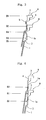
- the container as a whole is of the shape of a cup, has a body wall 1 and a bottom wall 2 closing the lower end of the body wall 1, the upper end of the body wall 1 being opened to form a mouth portion which is forming a flange 3 at an upper end of the body wall 1. That is, after the content such as a food or a beverage is contained in the container, the flange 3 is heat-sealed with a sealing foil (not shown) such as an aluminum foil, and the container is put to the vending.
- the bottom wall 2 may be formed flat as a whole. As shown in Fig.
- the bottom wall 2 is recessed to some extent from the lower end of the body wall 1 from the standpoint of stability when the container is placed and resistance against the deformation. Further, the container as a whole is transparent but the flange 3 is often opaque.
- a thick portion 2a which is the remaining portion of gate stemming from the injection gate is formed at the center of the bottom wall 2.
- the thickness of the thick portion 2a is relatively greater than other portions of the bottom wall 2 and, usually, protrudes to a height t of about 0.1 to about 3.0 mm though it may vary depending upon the size of the container, use and stretching ratio at the time of stretch-forming that will be described later.
- the thick portion 2a is formed when a preform that will be described later is formed by injection forming.
- the present invention has a feature in that the bottom wall 2 except the thick portion 2a therein, the body wall 1 and, as required, the flange 3 are oriented and crystallized, and are, further, heat-set, but the thick portion 2a present at the center of the bottom wall 2 remains substantially amorphous.
- the fact that the thick portion 2a at the center of the bottom wall 2 remains amorphous means that this portion has not been substantially stretched, has not been oriented or crystallized and, besides, has not been heat-set.
- the thick portion 2a of the container of the invention has a crystallinity of smaller than 15% and, desirably, as very small as not larger than 5% as measured by the densitometry, and is substantially amorphous while other portions are oriented and crystallized.
- the bottom wall 2 except the thick portion 2a has a crystallinity of not smaller than 15% and, particularly, the body wall 1 has a crystallinity of not smaller than 35%.
- the thick portion 2a which remains substantially amorphous exhibits flexibility or elasticity specific to the amorphousness, providing a function for improving the shock resistance.
- the container of the invention exhibits excellent heat resistance and excellent shock resistance despite of having the thick portion 2a that stems from the remaining portion of the injection gate.
- the container of the invention (Example 1) having the amorphous thick portion 2a exhibits very excellent heat resistance and shock resistance yet maintaining transparency in the thick portion 2a.
- the container (Comparative Example 1) having the thick portion 2a that is heat-fixed on the other hand, spherulites are formed in the thick portion 2a.
- the shock resistance decreases conspicuously and, besides, the thick portion 2a is opaque.
- the thermoplastic polyester resin that constitutes the above container is, particularly, a polyester resin that exhibits excellent transparency and shock resistance due to stretching and that can be effectively heat-set.
- a polyethylene terephthalate, a polypropylene terephthalate and a polyester comprising polylactic acid as a chief constituent component, that have glass transition points of not lower than room temperature and crystallinity Particularly, it is desired to use a polyethylene terephthalate having ethylene terephthalate units of not less than 80 mol% and, particularly, not less than 90 mol% from the standpoint of economy, formability and properties of the formed body.
- the copolymerizable components when the above polyethylene terephthalate is used are, desirably, isophthalic acid, 2,6-naphthalenedicarboxylic acid, 1,4-butanediol and 1,4-cyclohexanedimethanol.
- isophthalic acid 2,6-naphthalenedicarboxylic acid
- 1,4-butanediol 1,4-cyclohexanedimethanol
- the thermoplastic polyester resin the polyethylene terephthalate is most desired.
- polyethylene/butylene terephthalate polyethylene terephthalate/2,6-naphthalate, polyethylene terephthalate/isophthalate, or a blend thereof with polybutylene terephthalate, polybutylene terephthalate/isophthalate, polyethylene-2,6-naphthalate, polybutylene terephthalate/adipate, polyethylene-2,6-naphthalate/isophthalate, or polybutylene terephthalate/adipate or two or more kinds thereof.
- the polyester has an intrinsic viscosity [IV] of not smaller than 0.5 and, particularly, in a range of 0.6 to 1.5 as measured by using, as a solvent, a phenol/tetrachloroethane mixed solvent from the standpoint of formability of a preform, formability of a container, and mechanical properties and heat resistance of the container.
- the polyester may be blended with at least one of ethylene polymer, thermoplastic elastomer, polyacrylate or polycarbonate as a reforming resin component. It is desired that the reforming resin component is, usually, used in an amount of up to 60 parts by weight and, particularly preferably, in an amount of 3 to 20 parts by weight per 100 parts by weight of the polyester.
- thermoplastic polyester resin that constitutes the above container may be blended with known blending agents, such as antioxidant, heat stabilizer, ultraviolet ray absorber, antistatic agent, filler, lubricant and inorganic or organic coloring agent.
- known blending agents such as antioxidant, heat stabilizer, ultraviolet ray absorber, antistatic agent, filler, lubricant and inorganic or organic coloring agent.
- the cup-shaped containers shown in Fig. 1 are preserved or transported in a state of being stacked one upon the other.
- the containers of the upper sides deeply fit into the containers of the lower sides due to their own weights and it becomes difficult to separate the stacked containers from each other.
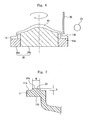
- the body wall 1 of the container is formed in a shape as shown in Fig. 2 .
- the upper end portion 4 (portion continuous to the flange 3) of the body wall 1 is a point from where the stretching starts and is formed relatively thick due to such a reason that the flange 3 (particularly, the back surface of the flange 3) has been heat-crystallized.
- a bead portion 5 is formed under the thick portion 4 and, further, an annular stepped portion 7 (hereinafter often referred to as stack portion) is formed protruding inward under the bead portion 5.
- stack portion annular stepped portion 7
- the outer surface of the stack portion 7 of an upper container A comes in contact with the upper surface of the bead portion 5 of a lower container B to maintain the stacked state. This makes it possible to effectively alleviate such an inconvenience that the upper container A falls deeply into the lower container B, i.e., to effectively alleviate such an inconvenience it becomes difficult to separate the upper container A and the lower container B from each other.
- the overlapping width d can be increased making it possible to stack the containers maintaining stability.
- limitation is imposed on the inner diameter of the flange 3 (container mouth portion) or on the shape of the body wall 1a near the flange 3. Therefore, stabilization in the stacking by the formation of the bead portion 5 is very meaningful. It is, for instance, desired that the overlapping width d of the upper container A and the lower container B is set to be not smaller than 0.5 mm and, particularly, not smaller than 0.8 mm.
- the bead portion 5 is so formed that a difference (D3 - D4) between the inner diameter D3 of the body wall 1a and the inner diameter D4 of the bead portion 5 is not smaller than 1.0 mm.
- the inner diameter D5 of the stack portion 7 should be set to be smaller than the inner diameter D4 of the bead portion 5 so that the outer surface of the stack portion (annular stepped portion) 7 of the upper container A is stably held by the upper surface of the bead portion 5.
- the bead portion 5 may be so formed that the container is stacked without being tilted. Namely, the bead portion 5 may be formed like a ring over the whole circumference of the body wall 1, or a plurality of pad portions 5 may be locally and symmetrically formed on the body wall 1.
- the containers can be stacked one upon the other maintaining stability.
- the bead portion 5 works as a reinforcing rib to improve the mechanical strength of the body wall 1.
- the polyester container of the present invention is produced by heating a preform of the shape of a sheet and of nearly a disk formed by injection-forming the above thermoplastic polyester resin at a predetermined heat-forming temperature and effecting the stretch-forming through steps shown in Figs. 5(a) to 5(e) .
- the preform (designated at 10 in Fig. 5 ) is obtained in substantially an amorphous state, and the central portion thereof (designated at 10a in Fig. 5 ) is formed thick being corresponded to the center of the bottom wall 2. Namely, the thick portion is the remaining portion of the injection gate corresponding to the injection gate of the injection-forming machine.
- the temperature for heating the preform 10 at the time of stretch-forming is not lower than a glass transition temperature (Tg) of the thermoplastic polyester resin that constitutes the preform but is lower than a crystallization starting temperature (Tic) thereof. If the heating temperature is lower than the glass transition temperature (Tg), an excess of force is needed for the heat-forming at steps that will be described below. If the heating temperature is not lower than the crystallization starting temperature (Tic), on the other hand, spherulites are formed and the transparency tends to be impaired.
- Tg glass transition temperature
- Tic crystallization starting temperature
- the glass transition temperature (Tg) and the crystallization starting temperature (Tic) used in the specification are found from a DSC curve that is obtained by picking up about 10 mg of the formed body that is to be measured, holding the sample at 300°C for 3 minutes in a nitrogen gas atmosphere, quickly cooling the sample down to room temperature, and elevating the temperature at a heating rate of 20°C a minute by using a differential scanning calorimeter (DSC).
- DSC differential scanning calorimeter
- the preform 10 heated at the above temperature is tightened on a forming metal mold (female metal mold) 14 by using an annular tightening member 12.
- a stretching rod 16 is extending through the annular tightening member 12, a communication hole is formed in the central portion of the forming metal mold 14, and a cooling rod 18 is extending through the communication hole. These rods are allowed to move up and down and, particularly, the cooling rod 18 moves following the stretching rod 16.
- the end surface of the cooling rod 18 is, usually, of nearly a size capable of coming in contact with the whole thick portion formed at the central portion 10a of the preform 10 while the end surface of the stretching rod 16 is larger than the end surface of the cooling rod 18.
- the stretching rod 16 and the cooling rod 18 have gas flow passages formed therein in the axial direction thereof.
- the circumferential edge portion 11 (corresponding to the flange 3 of the container of Fig. 1 ) of the preform 10 is preheated and is heat-crystallized to impart heat resistance thereto.
- the step of heat-crystallization will be described later.
- the circumferential edge portion 11 of the preform 10 is held by the forming metal mold 14 and by the annular tightening member 12.
- the tightening pressure is desirably increased to pressurize with a pressure of about 4.5 to about 13 MPa.
- the circumferential edge portion 11 that is heated at higher than the glass transition temperature is stretched and its thickness decreases down to, for example, about one-third to one-half. Therefore, the circumferential edge portion 11 is oriented and crystallized by the flow of resin and heat resistance is imparted thereto.
- a suitable lubricant such as silicone oil to the upper surface and lower surface of the circumferential edge portion 11 of the preform 10, or to the lower surface of the annular tightening member 12 or to the upper surface of the forming metal mold 14.
- Stretching is effected as shown in Fig. 5(b) following the step of tightening the mold for the preform 10. That is, in the step of stretching, the stretching rod 16 is stretched, the central portion of the preform 10 (corresponding to the thick portion 2a at the center of bottom of the container of Fig. 1 ) is held between the stretching rod 16 and the cooling rod 18, to thereby effect the stretching in the axial direction by using the stretching rod 16 and the blow-stretching.
- the stretching is effected in the axial direction by stretching the stretching rod 16 in the axial direction.
- the cooling rod 18 moves following the stretching rod 16 that stretches. That is, no excess of pressure acts on the portion (central portion 10a of the preform 10) held by the rods 16 and 18. Besides, this portion is cooled by the cooling rod 18. Accordingly, fluidization of the resin is effectively suppressed in this portion.
- the orientation and crystallization are suppressed at the central portion 10a of the preform 10, i.e., at the portion corresponding to the thick portion 2a at the center of bottom of the container. Therefore, the amorphous state is maintained at the portion corresponding to the thick portion 2a at the center of bottom of the container.
- the cooling rod 18 retreats to a position recessed from the cavity surface 14a of the forming metal mold 14 by the thickness of the thick portion. Thereafter, the compressed air or the like is blown out from the gas flow passage formed in the stretching rod 16 to effect the blow-stretching. Therefore, the preform 10 is formed in the shape of the cavity surface 14a of the forming metal mold 14 while leaving the thick portion at the central portion 10a of the preform 10.
- the portions other than the central portion 10a are oriented and crystallized to enhance the heat resistance.
- the stretch-formed body 20 obtained above is heat-set.
- the heat-setting is effected by bringing the stretch-formed body 20 into contact with the cavity surface 14a of the forming metal mold 14 that is heated to the heat-setting temperature in order to accelerate the crystallization while relaxing the distortion caused by forming. This further contributes to improve the heat resistance and the mechanical strength.
- the heat-setting temperature is higher than a crystallization initiating temperature (Tic) of the thermoplastic polyester forming the preform 10 (stretch-formed body 20) but is lower than a melting point (Tm) thereof and, particularly, is not higher than the melting point (Tm) - 10°C (usually, about 180°C).
- the heat-setting temperature is not lower than the melting point (Tm), it is probable that the stretch-formed body 20 melt-adheres to the forming metal mold 14. If the heat-setting temperature is lower than the crystallization initiating temperature (Tic), the crystallization is not sufficient, distortion due to forming is not sufficiently relaxed, and heat resistance and strength are not obtained. Further, the heat-fixing time is, usually, about 0.5 to about 5 seconds though it may vary depending upon the level of heat resistance that is desired.
- the central portion 20a of the stretch-formed body 20 (corresponds to the central portion 10a of the preform 10) is not in contact with the forming metal mold 14 but is in contact with the cooling rod 18 and is cooled. Therefore, no heat-setting is effected for the thickly formed central portion 20a that is the remaining portion of the injection gate. As a result, the central portion 20a is maintained in the amorphous state but other portions (e.g., bottom portion excluding the central portion 20a, body portion and flange) are heat-fixed. That is, if the thickly formed central portion 20a is heated at the heat-setting temperature, spherulites form causing a decrease in the shock resistance and impairing the transparency. By maintaining the thick central portion 20a amorphous, however, the transparency is maintained, and flexibility and elasticity are imparted owing to the amorphous property effectively alleviating a decrease in the shock resistance.
- the forming metal mold 14 can be easily heated to the heat-fixing temperature by providing heating means such as a heater in the forming metal mold 14.
- the above heating may be effected after the stretch-forming.
- the forming metal mold 14 is heated at the heat-setting temperature in advance and, in this state, the above step of tightening and the step of stretching are conducted, and the heating is discontinued after the heat-setting has been finished.
- the cooling rod 18 is cooled by a suitable coolant and its temperature is so set that at least the central portion 20a of the stretch-formed body 20 is lower than the heat-setting temperature (particularly, lower than the glass transition temperature in the step of stretching).
- the heat-setting temperature particularly, lower than the glass transition temperature in the step of stretching.
- the central portion of the stretch-formed body 20 or of the preform 10 is not elevated to be higher than the heat-setting temperature or the glass transition temperature by the radiation of heat.
- a cooling core metal mold 22 is inserted through an annular space of the annular tightening member 12 [ Fig. 5(d) ].
- the shape of outer surface of the cooling core metal mold 22 corresponds to the shape of the container shown in Fig. 1 .
- a recessed portion forming the bead portion and a stepped surface are formed in the outer surface of the cooling core metal mold 22 at corresponding positions.
- a compressed gas such as the compressed air is blown from the gas flow passage of the cooling rod 18.
- the gas is sucked under a reduced pressure through the gas flow passage of the stretching rod 16 to effect the shrink back [ Fig. 5(e) ]. Due to the shrink back, the stretch-formed body 20 is formed in the shape of the final container and is quickly cooled. By taking out the stretch-formed body 20, a container having the final shape is obtained as shown in Fig. 1 or 2 .
- the above-mentioned method makes it possible to obtain the container as shown in Fig. 1 or 2 .
- the thick portion 2a formed at the central portion of the bottom portion 2 is substantially amorphous while other portions are oriented, crystallized and are heat-fixed.
- the thick portion 2a at the center of the bottom wall 2 is not oriented, crystallized or heat-set. Therefore, excellent heat resistance and shock resistance are exhibited.
- the preform 10 formed by injection-forming is heat-crystallized for its circumferential edge portion 11 (corresponds to the flange 3) to enhance its heat resistance prior to effecting the forming through the above step.
- the circumferential edge portion (hereinafter called flange) 11 is wholly heat-crystallized, however, it becomes difficult to effect the heat-sealing. Therefore, the back surface of the flange 11 is selectively heat-crystallized by being selectively heated to maintain, in the amorphous state, the surface of the flange 11 to which various lid members will be fixed by heat-sealing.
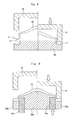
- the selective heat-crystallization is conducted by holding the preform 10 upside down on a cooling jig 30 as shown in Fig. 6.
- Fig. 6 and the succeeding drawings do not show the thick portion 20a of the preform 10 that stems from the remaining portion of the gate formed by the injection-forming.
- the cooling jig 30 has a ring-like support fitting 30a and a core-support fitting 30b which are formed by using a metal material such as a stainless steel, aluminum or a steel, and are, as required, so constituted that a coolant such as cooling water or the like circulates therein. Or, the jig 30 has heat-radiating fins formed thereon. Besides, the ring-like support fitting 30a and the core support fitting 30b are integrally coupled together so as to rotate together. The ring-like support fitting 30a is supporting the surface 11a of flange 11 of the preform 10 and the core support fitting 30b is supporting the inner surface of the stretch-formed portion of the preform 10.
- the stretch-formed portion is a central portion of the preform 10 surrounded by the flange 11, and is the portion that is stretch-formed as described above. That is, in conducting the heat-treatment as described below, the surface 11a of flange 11 of the preform 10 and the stretch-formed portion are effectively suppressed by these members 30a and 30b from being heated at temperatures higher than the heat-crystallization temperature.
- a heat source 33 is provided on the side of the back surface 11b of flange 11 of the preform 10 to selectively heat the back surface 11b of flange 11, to improve the strength and heat resistance of the flange 11 by the heat-crystallization, and to maintain the surface 11a of flange 11 in the amorphous state. Further, the stretch-formed portion of the preform 10 is prevented from being heat-crystallized, so that no inconvenience occurs in the stretch-forming that is caused by an increase in the softening point or the like.
- the heat-crystallization is effectively executed by the selective heating since the preform 10 is held upside down.
- the heating is effected from the side of the back surface 11b of flance 11 by holding the preform 10 upright, the flange 11 is softened by heating and a gap forms between the surface 11a of the flange 11 and the ring-like support fitting 30a for cooling. Therefore, the surface 11a of the flange is not effectively cooled and this portion, too, is heat-crystallized (if the surface 11a of the flange is heat-crystallized, it becomes difficult to fix the lid member or the like thereto by heat-sealing).
- the heat source 33 there can be used a carbonic acid gas laser, a near infrared-ray heater, a far infrared-ray heater, or a hot air heater.
- the heating is effected by the heat source 33 of which the position has been fixed while rotating the cooling jig 30.
- the carbonic acid gas laser is used, the portion irradiated with laser can be easily adjusted offering an advantage of selectively heating the back surface 11b of the flange 11.
- other means is used as the heat source 33, it is not easy to adjust the heated portion. As shown, for example, in Fig.
- the shielding member 35 is formed by using a metal having high heat conductivity. Provision of the shielding member 35 effectively prevents the stretch-formed portion of the preform 10 from being heated, and enables the back surface 11b of the flange 11 to be efficiently and selectively heated.
- the core support fitting 30b for cooling is intimately adhered onto the whole inner surface of the stretch-formed portion of the preform 10 and offers advantages of reducing the load exerted on the surface 11a of the flange and effectively preventing the flange 11 from being deformed by heating.
- the whole inner surface of the stretch-formed portion of the preform 10 does not have to be closely contacted to the core support fitting 30b unless the stretch-formed portion is heated to be higher than the heat-crystallization temperature.
- a suitable space may be formed between the central portion 20a of the stretch-formed portion and the core support fitting 30b.
- the surface 11a of the flange of the preform 10 In order to reliably maintain amorphous the surface 11a of the flange in the above step of selective heat-crystallization, it is desired to provide the surface 11a of flange of the preform 10 with an annular protuberance 37 as shown in Fig. 7 .
- the annular protuberance 37 has a substantially flat surface 37a at the upper end. If the selective heat-crystallization is effected by providing the above annular protuberance 37, it is allowed to reliably suppress the heat-crystallization in the flat surface 37a of the annular protuberance 37 and the lid member can be easily fixed to the above portion by heat-sealing.
- the height h of the annular protuberance 37 is about 0.1 to about 2 mm. From the standpoint of maintaining a sufficient width of heat-sealing, it is desired that the width w of flat surface 37a of the annular protuberance 37 is about 0.5 to about 3.0 mm.
- the flange 11 forming the annular protuberance 37 is to be selectively heat-crystallized, it is desired that the flat surface 37a only of the annular protuberance 37a is brought into contact with the annular support fitting 30a for cooling but other portions of the flange surface 11a are floating a from the standpoint of conducting the efficient cooling.
- the flange 11 is held from the back surface thereof by a cooling upper mold 41 while slightly broadening the mouth diameter of the flange 11 by using a cooling lower mold 39 as shown in Fig. 8 after the above selective heating while the flange 11 is still in a softened state, and the flange 11 is tightened with a suitable pressure and is cooled and fixed to a suitable size. As shown in Fig.
- annular cooling lower mold 30c for limiting the mouth diameter is provided so as to slide between the annular support fitting 30a and the core support fitting 30b. Therefore, the annular support fitting 30a for cooling can be utilized as the cooling lower mold 39 that is shown in Fig. 8 .
- the annular cooling lower mold 30c for limiting the mouth diameter is elevated and is inserted in the mouth of the flange 11 and, at the same time, the cooling upper mold 41 is lowered to tighten the flange 11 relative to the annular support fitting 30a.
- the preform 10 with the back surface 11b of the flange 11 being selectively heat-crystallized and with the surface 11a of the flange 11 being maintained amorphous, is subjected to the above step of stretch-forming and is formed into a container.
- Crystallinity ⁇ ⁇ c ⁇ ⁇ c x ⁇ - ⁇ ⁇ a / ⁇ x ⁇ c - ⁇ a x 100
- the density was measured by using an n-heptane-carbon tetrachloride type density-gradient tube (manufactured by Ikeda Rika Co.) under a condition of 20°C.
- the containers were each filled with 200 ml of water and were sealed. Thereafter, the containers were fallen from a height of 80 cm with their bottoms facing downward. The containers were repetitively fallen 5 times. Thereafter, the bottom portions were checked for their deformation by eyes and were evaluated to be ⁇ when there was no crack.
- the centers of the bottom portions were measured for their transparency (haze) by using a hazeometer manufactured by Suga Shikenki Co.
- the centers of the bottoms were evaluated to be ⁇ when the haze was not higher than 10%.
- a polyethylene terephthalate resin having an intrinsic viscosity of 0.8 dl/g (SA135 manufactured by Mitsui Kagaku Co., containing 2 mol% of isophthalic acid) was fed to an injection-forming machine (NN75JS manufactured by Niigata Tekkojo Co.), and was injection-formed under the conditions of an injection temperature of 275 to 300°C and an injection pressure of 10 Kg/cm 2 to obtain 15.6 g of a substantially amorphous preform of a single layer.
- the flange portion of the preform was heated up to 180°C and was heat-crystallized by the irradiation by using a near infrared-ray heater.
- the preform was heated at 95°C which was higher than the glass transition temperature thereof, and was formed according to a process of Figs. 5 (a) to 5 (e) to obtain a cup-like container with a flange.
- the forming metal mold was maintained at a temperature of 180°C while the cooling rod and the cooling core metal mold were maintained at 30°C.
- Table 1 shows the sizes of the tools, measured results of the crystallinity and evaluated results of the properties.
- the central portion of the bottom portion was amorphous and the bottom portion surrounding the central portion was oriented and crystallized exhibiting sufficiently practicable properties concerning both heat resistance and shock resistance.
- a cup-like container with a flange was obtained under the same conditions as those of Example but without using the cooling rod in the process of Figs. 5(a) to 5(e) .
- Table 1 shows the sizes of the tools, measured results of the crystallinity and evaluated results of the properties.
Landscapes
- Engineering & Computer Science (AREA)
- Mechanical Engineering (AREA)
- Manufacturing & Machinery (AREA)
- Ceramic Engineering (AREA)
- Physics & Mathematics (AREA)
- Thermal Sciences (AREA)
- Blow-Moulding Or Thermoforming Of Plastics Or The Like (AREA)
- Processing And Handling Of Plastics And Other Materials For Molding In General (AREA)
- Containers Having Bodies Formed In One Piece (AREA)
Claims (11)
- Récipient en polyester (A) obtenu au moyen d'une opération de formage par étirage d'une préforme (10) en résine de polyester thermoplastique formée par une opération de formage par injection caractérisé en ce que :une partie centrale (2a) d'une paroi de fond (2) est la partie restante de l'entrée au moment de l'opération de formage par injection, et est formée de manière relativement plus épaisse par rapport à une partie de paroi de fond entourant la partie centrale (2a) ;la partie centrale (2a) de la paroi de fond (2) est sensiblement amorphe et la partie de paroi de fond entourant la partie centrale (2a) est orientée et cristallisée ;la paroi de fond (2) autre que la partie centrale a une cristallinité ne faisant pas moins de 15 % ; etla cristallinité n'est pas inférieure à 15 % au niveau d'une position se trouvant à 10 mm du centre du fond.
- Récipient en polyester (A) selon la revendication 1, dans lequel un rebord (3) est formé au niveau d'une extrémité supérieure d'une paroi de corps (1) de manière continue par rapport à la paroi de fond (2).
- Récipient en polyester (A) selon la revendication 2, dans lequel une partie de contre-bague (5) faisant saillie vers l'intérieur et une partie à gradins (7) sont formées dans une partie supérieure de la paroi de corps (1), la partie à gradins (7) étant positionnée sous la partie de contre-bague (5) et faisant saillie vers l'intérieur.
- Procédé de fabrication d'un récipient en polyester (A) selon l'une quelconque des revendications 1 à 3, comportant :l'étape consistant à former une préforme (10) en résine de polyester thermoplastique par une opération de formage par injection ;l'étape consistant à tenir la partie restante de l'entrée d'injection de la préforme (10) entre une barre d'étirage (16) et une barre de refroidissement (18) ;l'étape consistant à étirer dans le sens axial en étirant la barre d'étirage (16) et en amenant la barre de refroidissement (18) à se déplacer à la suite de la barre d'étirage (16) et, par ailleurs, l'étape consistant à étirer par soufflage par le soufflage d'un fluide ;caractérisé par, l'étape consistant à mettre une surface extérieure du corps formé par étirage (20) en contact avec une surface d'un moule métallique chauffé (14) qui est maintenu chauffé par une opération d'étirage par soufflage à l'exception de la partie avec laquelle la barre de refroidissement (18) est en contact, afin de former le corps formé (20) pour lui faire prendre la forme d'un récipient (A) ; etl'étape consistant à effectuer une opération de fixage thermique par une opération de chauffage par le contact avec la surface du moule métallique chauffé (14) à l'exception d'une partie avec laquelle la barre de refroidissement (18) est en contact.
- Procédé de fabrication selon la revendication 4, dans lequel, après l'opération de fixage thermique, un moule métallique à noyau de refroidissement (22) est inséré dans le corps formé par étirage (20) formé pour lui faire prendre la forme d'un récipient (A), et le corps formé par étirage (20) est contracté à nouveau pour lui faire prendre la forme du moule métallique à noyau (22), ceci étant suivi du refroidissement.
- Procédé de fabrication selon la revendication 4, dans lequel une surface arrière d'un rebord (3) formé sur la préforme (10) est cristallisée à la chaleur de manière sélective avant de tenir la partie restante de l'entrée d'injection de la préforme (10) entre la barre d'étirage (16) et la barre de refroidissement (18).
- Procédé de fabrication selon la revendication 6, dans lequel la préforme (10) est mise dans une position renversée, et le côté surface arrière du rebord (3) est chauffé de manière sélective afin d'être cristallisé à la chaleur en tenant le côté surface avant du rebord (3) en utilisant un gabarit conformateur (30).
- Procédé de fabrication selon la revendication 7, dans lequel le gabarit conformateur (30) comporte un raccord de support similaire à une bague (30a) et un raccord de support de noyau (30b) positionné dans la bague (30a), le côté surface avant (1 la) du rebord (11) est tenu par le raccord de support similaire à une bague (30a) au moment de chauffer de manière sélective le côté surface arrière (11b) du rebord (11), et une surface intérieure de la partie formée par étirage de la préforme (10) entourée par le rebord (11) est tenue par le raccord de support de noyau (30b).
- Procédé de fabrication selon la revendication 8, dans lequel, sur le côté surface arrière de la préforme (10), une plaque de protection (35) qui supprime la conduction de la chaleur est agencée à proximité d'une partie limite entre le rebord (11) et la partie formée par étirage (20) pour chauffer de manière sélective le côté surface arrière du rebord (11).
- Procédé de fabrication selon la revendication 4, dans lequel, après que le côté surface arrière du rebord (11) a été chauffé de manière sélective, le rebord (11) est fixé par serrage à des fins de stabilisation de la taille du rebord (11).
- Procédé de fabrication selon la revendication 5, dans lequel une partie en retrait et une surface à gradins correspondant à la partie de contre-bague (5) et à la partie annulaire à gradins (7) formées dans la paroi de corps (1) du récipient (A), sont formées dans la surface extérieure du moule métallique à noyau de refroidissement (22).
Applications Claiming Priority (3)
| Application Number | Priority Date | Filing Date | Title |
|---|---|---|---|
| JP2004219216 | 2004-07-27 | ||
| JP2004221703A JP4635506B2 (ja) | 2004-07-29 | 2004-07-29 | 耐熱性と耐衝撃性とに優れたポリエステル容器及びその製造方法 |
| PCT/JP2005/013991 WO2006011612A1 (fr) | 2004-07-27 | 2005-07-25 | Recipient en polyester offrant une excellente resistance a la chaleur et aux chocs, et son procede de fabrication |
Publications (3)
| Publication Number | Publication Date |
|---|---|
| EP1772251A1 EP1772251A1 (fr) | 2007-04-11 |
| EP1772251A4 EP1772251A4 (fr) | 2011-12-28 |
| EP1772251B1 true EP1772251B1 (fr) | 2015-11-18 |
Family
ID=35786355
Family Applications (1)
| Application Number | Title | Priority Date | Filing Date |
|---|---|---|---|
| EP05767371.7A Expired - Lifetime EP1772251B1 (fr) | 2004-07-27 | 2005-07-25 | Recipient en polyester offrant une excellente resistance a la chaleur et aux chocs, et son procede de fabrication |
Country Status (5)
| Country | Link |
|---|---|
| US (1) | US7833467B2 (fr) |
| EP (1) | EP1772251B1 (fr) |
| KR (1) | KR101199692B1 (fr) |
| CN (1) | CN101027177B (fr) |
| WO (1) | WO2006011612A1 (fr) |
Families Citing this family (11)
| Publication number | Priority date | Publication date | Assignee | Title |
|---|---|---|---|---|
| ITMO20040034A1 (it) * | 2004-02-16 | 2004-05-16 | Benco Pack Spa | Formatura di contenitori |
| DE102004014653B4 (de) * | 2004-03-25 | 2022-10-20 | Krones Aktiengesellschaft | Verfahren und Vorrichtung zum Herstellen eines insbesondere wärmebeständigen Hohlkörpers |
| DE102008014215A1 (de) * | 2008-03-13 | 2009-09-17 | Krones Ag | Vorrichtung zum Erwärmen von Behältnissen |
| CN102529068B (zh) * | 2010-12-30 | 2014-07-23 | 合默麟开发有限公司 | 薄壁端口结晶的方法 |
| DE102013016453A1 (de) * | 2013-10-02 | 2015-04-02 | Isk Iserlohner Kunststofftechnologie Gmbh | Verfahren und Vorrichtung zur Herstellung eines Bauteils in einem Formungsprozess und Bauteil |
| GB2552023B (en) * | 2016-07-08 | 2020-03-25 | Gr8 Eng Ltd | Container and manufacture thereof |
| KR101731960B1 (ko) * | 2016-07-21 | 2017-05-04 | (주)동희산업 | 차량용 고압용기 |
| US10486891B2 (en) | 2016-12-02 | 2019-11-26 | S.C. Johnson & Son, Inc. | Plastic bottle for a pressurized dispensing system |
| JP6930263B2 (ja) * | 2017-07-20 | 2021-09-01 | 東洋製罐株式会社 | ポリエステル系樹脂製容器の製造方法、及びブロー成形型 |
| GB2580685B (en) * | 2019-01-24 | 2021-04-28 | Softform Ltd | A method and tool for manufacturing a container from a thermoplastic material |
| GB202214806D0 (en) * | 2022-10-07 | 2022-11-23 | Par Pak Europe Ltd | A method of thermoforming plastics containers |
Family Cites Families (23)
| Publication number | Priority date | Publication date | Assignee | Title |
|---|---|---|---|---|
| GB1395026A (en) * | 1972-03-16 | 1975-05-21 | Itw Ltd | Cups for holding ingredients for drinks |
| JPS50156439U (fr) | 1974-06-12 | 1975-12-25 | ||
| JPS5381570A (en) * | 1977-10-07 | 1978-07-19 | Dainippon Printing Co Ltd | Molding method and apparatus for container comprising thermoplastic foamed synthetic resin |
| SE429317B (sv) | 1980-05-29 | 1983-08-29 | Plm Ab | Sett att astadkomma ett element av polyetylentereftalat eller dermed liknande termoplastmaterial jemte anordning herfor |
| JPS62187012A (ja) * | 1986-02-13 | 1987-08-15 | Toyo Seikan Kaisha Ltd | 中空容器の製造法 |
| JPH0735085B2 (ja) | 1990-10-05 | 1995-04-19 | 日精エー・エス・ビー機械株式会社 | 2軸延伸結晶性樹脂容器およびその製造方法 |
| US5290506A (en) | 1991-04-30 | 1994-03-01 | Nissei Asb Machine Co., Ltd. | Process of injection stretch blow molding hollow article having thick-walled bottom |
| JPH0671762B2 (ja) | 1991-04-30 | 1994-09-14 | 日精エー・エス・ビー機械株式会社 | 厚肉の底壁を有する中空体の射出延伸吹込成形方法 |
| JPH05246416A (ja) | 1992-02-29 | 1993-09-24 | Nissei Asb Mach Co Ltd | 合成樹脂製自立壜 |
| ATE157927T1 (de) * | 1992-07-07 | 1997-09-15 | Continental Pet Technologies | Verfahren zum formen von einem behälter mit einer seitenwand von hoher kristallinität und einem boden von niedriger kristallinität |
| US5281387A (en) * | 1992-07-07 | 1994-01-25 | Continental Pet Technologies, Inc. | Method of forming a container having a low crystallinity |
| JPH06134850A (ja) * | 1992-07-28 | 1994-05-17 | Toppan Printing Co Ltd | プラグアシスト成形方法 |
| JP2998559B2 (ja) * | 1994-05-13 | 2000-01-11 | 東洋製罐株式会社 | ワンピース型耐熱ポリエステルボトル及びその製法 |
| CA2159169C (fr) * | 1994-09-27 | 2006-05-16 | Tony Salemi | Appareil de moulage par soufflage/injection de bouteilles de plastique et procede ameliore |
| PE24697A1 (es) * | 1995-03-29 | 1997-09-01 | Continental Pet Technologies | Envase presurizado para rellenar resistente al resquebrajamiento del bebedero, preforma y metodo para fabricarlos |
| JP3676426B2 (ja) * | 1995-05-25 | 2005-07-27 | 北海製罐株式会社 | ポリエチレンテレフタレート樹脂製ボトル |
| JPH1071641A (ja) * | 1996-08-31 | 1998-03-17 | Yoshino Kogyosho Co Ltd | 2軸延伸ブロー成形の成形金型装置 |
| US5902539A (en) * | 1996-12-06 | 1999-05-11 | Continental Pet Technologies, Inc. | Process for making PEN/PET blends and transparent articles therefrom |
| JP3449182B2 (ja) * | 1997-07-29 | 2003-09-22 | 東洋製罐株式会社 | 耐熱性延伸樹脂容器の製法 |
| US6485669B1 (en) * | 1999-09-14 | 2002-11-26 | Schmalbach-Lubeca Ag | Blow molding method for producing pasteurizable containers |
| JP4506018B2 (ja) * | 2001-03-29 | 2010-07-21 | 東洋製罐株式会社 | 耐熱性及び耐衝撃性容器 |
| JP2003159743A (ja) | 2001-11-28 | 2003-06-03 | Toyo Seikan Kaisha Ltd | 合成樹脂容器の製造方法 |
| JP4314794B2 (ja) * | 2002-08-20 | 2009-08-19 | 東洋製罐株式会社 | 二軸延伸ポリエステル容器の製造方法 |
-
2005
- 2005-07-25 CN CN2005800325962A patent/CN101027177B/zh not_active Expired - Fee Related
- 2005-07-25 WO PCT/JP2005/013991 patent/WO2006011612A1/fr not_active Ceased
- 2005-07-25 KR KR1020077004056A patent/KR101199692B1/ko not_active Expired - Fee Related
- 2005-07-25 EP EP05767371.7A patent/EP1772251B1/fr not_active Expired - Lifetime
- 2005-07-25 US US11/658,508 patent/US7833467B2/en not_active Expired - Fee Related
Also Published As
| Publication number | Publication date |
|---|---|
| WO2006011612A1 (fr) | 2006-02-02 |
| US7833467B2 (en) | 2010-11-16 |
| CN101027177B (zh) | 2010-09-29 |
| EP1772251A1 (fr) | 2007-04-11 |
| KR101199692B1 (ko) | 2012-11-08 |
| EP1772251A4 (fr) | 2011-12-28 |
| KR20070053228A (ko) | 2007-05-23 |
| CN101027177A (zh) | 2007-08-29 |
| US20070290415A1 (en) | 2007-12-20 |
Similar Documents
| Publication | Publication Date | Title |
|---|---|---|
| EP2358602B1 (fr) | Structure de base de récipient sensible à des forces associées au vide | |
| AU2004212495B2 (en) | Inverting vacuum panels for a plastic container | |
| EP1893496B1 (fr) | Structure de base d'un contenant sensible a des forces de depression | |
| EP1633640B1 (fr) | Contenant avec une structure de base sensible a des forces de depression | |
| US7455189B2 (en) | Rectangular hot-filled container | |
| EP0683029B1 (fr) | Récipient étiré biaxialement et moulé par soufflage ayant une excellente résistance à la chaleur et procédé de production | |
| US7857157B2 (en) | Container having segmented bumper rib | |
| US6012597A (en) | Polyester bottle with a handle and method of manufacturing the same | |
| US20060006133A1 (en) | Container base structure responsive to vacuum related forces | |
| EP1772251B1 (fr) | Recipient en polyester offrant une excellente resistance a la chaleur et aux chocs, et son procede de fabrication | |
| WO2002008068A1 (fr) | Structure de base d'un receptacle | |
| US8468785B2 (en) | Container for hot-filling | |
| JP7062352B2 (ja) | プラスチックボトル、充填体、及び充填体の製造方法 | |
| EP1897676B1 (fr) | Récipient réalisé en résine de polyester et son procédé de moulage | |
| JP6743360B2 (ja) | プラスチックボトル、充填体、及び充填体の製造方法 | |
| JP6780756B2 (ja) | 充填体の製造方法 | |
| EP1885604A1 (fr) | Contenant sterilisable en autoclave | |
| JP6786786B2 (ja) | プリフォーム、プリフォームの製造方法、及びプラスチックボトル | |
| JP4635506B2 (ja) | 耐熱性と耐衝撃性とに優れたポリエステル容器及びその製造方法 | |
| JP4449312B2 (ja) | 熱可塑性樹脂容器の製造方法 |
Legal Events
| Date | Code | Title | Description |
|---|---|---|---|
| PUAI | Public reference made under article 153(3) epc to a published international application that has entered the european phase |
Free format text: ORIGINAL CODE: 0009012 |
|
| 17P | Request for examination filed |
Effective date: 20070123 |
|
| AK | Designated contracting states |
Kind code of ref document: A1 Designated state(s): AT BE BG CH CY CZ DE DK EE ES FI FR GB GR HU IE IS IT LI LT LU LV MC NL PL PT RO SE SI SK TR |
|
| DAX | Request for extension of the european patent (deleted) | ||
| A4 | Supplementary search report drawn up and despatched |
Effective date: 20111124 |
|
| RIC1 | Information provided on ipc code assigned before grant |
Ipc: B29C 49/48 20060101ALI20111118BHEP Ipc: B29C 49/64 20060101ALI20111118BHEP Ipc: B29C 61/02 20060101ALI20111118BHEP Ipc: B29C 51/26 20060101ALN20111118BHEP Ipc: B29C 51/10 20060101ALN20111118BHEP Ipc: B29C 51/30 20060101ALN20111118BHEP Ipc: B29C 49/42 20060101ALN20111118BHEP Ipc: B65D 1/26 20060101AFI20111118BHEP Ipc: B29C 49/12 20060101ALI20111118BHEP |
|
| 17Q | First examination report despatched |
Effective date: 20121018 |
|
| RAP1 | Party data changed (applicant data changed or rights of an application transferred) |
Owner name: TOYO SEIKAN KAISHA, LTD. |
|
| REG | Reference to a national code |
Ref country code: DE Ref legal event code: R079 Ref document number: 602005047958 Country of ref document: DE Free format text: PREVIOUS MAIN CLASS: B29C0049420000 Ipc: B65D0001260000 |
|
| GRAJ | Information related to disapproval of communication of intention to grant by the applicant or resumption of examination proceedings by the epo deleted |
Free format text: ORIGINAL CODE: EPIDOSDIGR1 |
|
| GRAP | Despatch of communication of intention to grant a patent |
Free format text: ORIGINAL CODE: EPIDOSNIGR1 |
|
| RIC1 | Information provided on ipc code assigned before grant |
Ipc: B29C 49/48 20060101ALI20150519BHEP Ipc: B29C 49/64 20060101ALI20150519BHEP Ipc: B65D 1/26 20060101AFI20150519BHEP Ipc: B29C 51/30 20060101ALN20150519BHEP Ipc: B29C 45/00 20060101ALI20150519BHEP Ipc: B29C 61/02 20060101ALI20150519BHEP Ipc: B29C 49/42 20060101ALN20150519BHEP Ipc: B29C 51/04 20060101ALI20150519BHEP Ipc: B29C 49/06 20060101ALI20150519BHEP Ipc: B29C 51/26 20060101ALN20150519BHEP Ipc: B29C 51/10 20060101ALN20150519BHEP Ipc: B65D 1/16 20060101ALI20150519BHEP Ipc: B29L 31/00 20060101ALI20150519BHEP Ipc: B29C 49/12 20060101ALI20150519BHEP |
|
| INTG | Intention to grant announced |
Effective date: 20150608 |
|
| GRAS | Grant fee paid |
Free format text: ORIGINAL CODE: EPIDOSNIGR3 |
|
| GRAA | (expected) grant |
Free format text: ORIGINAL CODE: 0009210 |
|
| AK | Designated contracting states |
Kind code of ref document: B1 Designated state(s): AT BE BG CH CY CZ DE DK EE ES FI FR GB GR HU IE IS IT LI LT LU LV MC NL PL PT RO SE SI SK TR |
|
| REG | Reference to a national code |
Ref country code: GB Ref legal event code: FG4D |
|
| REG | Reference to a national code |
Ref country code: CH Ref legal event code: EP |
|
| REG | Reference to a national code |
Ref country code: AT Ref legal event code: REF Ref document number: 761426 Country of ref document: AT Kind code of ref document: T Effective date: 20151215 |
|
| REG | Reference to a national code |
Ref country code: IE Ref legal event code: FG4D |
|
| REG | Reference to a national code |
Ref country code: DE Ref legal event code: R096 Ref document number: 602005047958 Country of ref document: DE |
|
| REG | Reference to a national code |
Ref country code: NL Ref legal event code: MP Effective date: 20160218 |
|
| REG | Reference to a national code |
Ref country code: LT Ref legal event code: MG4D |
|
| REG | Reference to a national code |
Ref country code: AT Ref legal event code: MK05 Ref document number: 761426 Country of ref document: AT Kind code of ref document: T Effective date: 20151118 |
|
| PG25 | Lapsed in a contracting state [announced via postgrant information from national office to epo] |
Ref country code: ES Free format text: LAPSE BECAUSE OF FAILURE TO SUBMIT A TRANSLATION OF THE DESCRIPTION OR TO PAY THE FEE WITHIN THE PRESCRIBED TIME-LIMIT Effective date: 20151118 Ref country code: LT Free format text: LAPSE BECAUSE OF FAILURE TO SUBMIT A TRANSLATION OF THE DESCRIPTION OR TO PAY THE FEE WITHIN THE PRESCRIBED TIME-LIMIT Effective date: 20151118 Ref country code: IT Free format text: LAPSE BECAUSE OF FAILURE TO SUBMIT A TRANSLATION OF THE DESCRIPTION OR TO PAY THE FEE WITHIN THE PRESCRIBED TIME-LIMIT Effective date: 20151118 Ref country code: NL Free format text: LAPSE BECAUSE OF FAILURE TO SUBMIT A TRANSLATION OF THE DESCRIPTION OR TO PAY THE FEE WITHIN THE PRESCRIBED TIME-LIMIT Effective date: 20151118 Ref country code: IS Free format text: LAPSE BECAUSE OF FAILURE TO SUBMIT A TRANSLATION OF THE DESCRIPTION OR TO PAY THE FEE WITHIN THE PRESCRIBED TIME-LIMIT Effective date: 20160318 |
|
| PG25 | Lapsed in a contracting state [announced via postgrant information from national office to epo] |
Ref country code: SE Free format text: LAPSE BECAUSE OF FAILURE TO SUBMIT A TRANSLATION OF THE DESCRIPTION OR TO PAY THE FEE WITHIN THE PRESCRIBED TIME-LIMIT Effective date: 20151118 Ref country code: LV Free format text: LAPSE BECAUSE OF FAILURE TO SUBMIT A TRANSLATION OF THE DESCRIPTION OR TO PAY THE FEE WITHIN THE PRESCRIBED TIME-LIMIT Effective date: 20151118 Ref country code: PL Free format text: LAPSE BECAUSE OF FAILURE TO SUBMIT A TRANSLATION OF THE DESCRIPTION OR TO PAY THE FEE WITHIN THE PRESCRIBED TIME-LIMIT Effective date: 20151118 Ref country code: FI Free format text: LAPSE BECAUSE OF FAILURE TO SUBMIT A TRANSLATION OF THE DESCRIPTION OR TO PAY THE FEE WITHIN THE PRESCRIBED TIME-LIMIT Effective date: 20151118 Ref country code: AT Free format text: LAPSE BECAUSE OF FAILURE TO SUBMIT A TRANSLATION OF THE DESCRIPTION OR TO PAY THE FEE WITHIN THE PRESCRIBED TIME-LIMIT Effective date: 20151118 Ref country code: GR Free format text: LAPSE BECAUSE OF FAILURE TO SUBMIT A TRANSLATION OF THE DESCRIPTION OR TO PAY THE FEE WITHIN THE PRESCRIBED TIME-LIMIT Effective date: 20160219 Ref country code: PT Free format text: LAPSE BECAUSE OF FAILURE TO SUBMIT A TRANSLATION OF THE DESCRIPTION OR TO PAY THE FEE WITHIN THE PRESCRIBED TIME-LIMIT Effective date: 20160318 |
|
| REG | Reference to a national code |
Ref country code: FR Ref legal event code: PLFP Year of fee payment: 12 |
|
| PG25 | Lapsed in a contracting state [announced via postgrant information from national office to epo] |
Ref country code: CZ Free format text: LAPSE BECAUSE OF FAILURE TO SUBMIT A TRANSLATION OF THE DESCRIPTION OR TO PAY THE FEE WITHIN THE PRESCRIBED TIME-LIMIT Effective date: 20151118 |
|
| REG | Reference to a national code |
Ref country code: DE Ref legal event code: R097 Ref document number: 602005047958 Country of ref document: DE |
|
| PG25 | Lapsed in a contracting state [announced via postgrant information from national office to epo] |
Ref country code: EE Free format text: LAPSE BECAUSE OF FAILURE TO SUBMIT A TRANSLATION OF THE DESCRIPTION OR TO PAY THE FEE WITHIN THE PRESCRIBED TIME-LIMIT Effective date: 20151118 Ref country code: DK Free format text: LAPSE BECAUSE OF FAILURE TO SUBMIT A TRANSLATION OF THE DESCRIPTION OR TO PAY THE FEE WITHIN THE PRESCRIBED TIME-LIMIT Effective date: 20151118 Ref country code: SK Free format text: LAPSE BECAUSE OF FAILURE TO SUBMIT A TRANSLATION OF THE DESCRIPTION OR TO PAY THE FEE WITHIN THE PRESCRIBED TIME-LIMIT Effective date: 20151118 Ref country code: RO Free format text: LAPSE BECAUSE OF FAILURE TO SUBMIT A TRANSLATION OF THE DESCRIPTION OR TO PAY THE FEE WITHIN THE PRESCRIBED TIME-LIMIT Effective date: 20151118 |
|
| PLBE | No opposition filed within time limit |
Free format text: ORIGINAL CODE: 0009261 |
|
| STAA | Information on the status of an ep patent application or granted ep patent |
Free format text: STATUS: NO OPPOSITION FILED WITHIN TIME LIMIT |
|
| 26N | No opposition filed |
Effective date: 20160819 |
|
| PG25 | Lapsed in a contracting state [announced via postgrant information from national office to epo] |
Ref country code: SI Free format text: LAPSE BECAUSE OF FAILURE TO SUBMIT A TRANSLATION OF THE DESCRIPTION OR TO PAY THE FEE WITHIN THE PRESCRIBED TIME-LIMIT Effective date: 20151118 |
|
| PG25 | Lapsed in a contracting state [announced via postgrant information from national office to epo] |
Ref country code: BE Free format text: LAPSE BECAUSE OF FAILURE TO SUBMIT A TRANSLATION OF THE DESCRIPTION OR TO PAY THE FEE WITHIN THE PRESCRIBED TIME-LIMIT Effective date: 20151118 |
|
| REG | Reference to a national code |
Ref country code: CH Ref legal event code: PL |
|
| PG25 | Lapsed in a contracting state [announced via postgrant information from national office to epo] |
Ref country code: MC Free format text: LAPSE BECAUSE OF FAILURE TO SUBMIT A TRANSLATION OF THE DESCRIPTION OR TO PAY THE FEE WITHIN THE PRESCRIBED TIME-LIMIT Effective date: 20151118 |
|
| PG25 | Lapsed in a contracting state [announced via postgrant information from national office to epo] |
Ref country code: CH Free format text: LAPSE BECAUSE OF NON-PAYMENT OF DUE FEES Effective date: 20160731 Ref country code: LI Free format text: LAPSE BECAUSE OF NON-PAYMENT OF DUE FEES Effective date: 20160731 |
|
| REG | Reference to a national code |
Ref country code: IE Ref legal event code: MM4A |
|
| REG | Reference to a national code |
Ref country code: FR Ref legal event code: PLFP Year of fee payment: 13 |
|
| PG25 | Lapsed in a contracting state [announced via postgrant information from national office to epo] |
Ref country code: IE Free format text: LAPSE BECAUSE OF NON-PAYMENT OF DUE FEES Effective date: 20160725 |
|
| PG25 | Lapsed in a contracting state [announced via postgrant information from national office to epo] |
Ref country code: LU Free format text: LAPSE BECAUSE OF NON-PAYMENT OF DUE FEES Effective date: 20160725 |
|
| PG25 | Lapsed in a contracting state [announced via postgrant information from national office to epo] |
Ref country code: CY Free format text: LAPSE BECAUSE OF FAILURE TO SUBMIT A TRANSLATION OF THE DESCRIPTION OR TO PAY THE FEE WITHIN THE PRESCRIBED TIME-LIMIT Effective date: 20151118 Ref country code: HU Free format text: LAPSE BECAUSE OF FAILURE TO SUBMIT A TRANSLATION OF THE DESCRIPTION OR TO PAY THE FEE WITHIN THE PRESCRIBED TIME-LIMIT; INVALID AB INITIO Effective date: 20050725 |
|
| PG25 | Lapsed in a contracting state [announced via postgrant information from national office to epo] |
Ref country code: TR Free format text: LAPSE BECAUSE OF FAILURE TO SUBMIT A TRANSLATION OF THE DESCRIPTION OR TO PAY THE FEE WITHIN THE PRESCRIBED TIME-LIMIT Effective date: 20151118 |
|
| REG | Reference to a national code |
Ref country code: FR Ref legal event code: PLFP Year of fee payment: 14 |
|
| PG25 | Lapsed in a contracting state [announced via postgrant information from national office to epo] |
Ref country code: BG Free format text: LAPSE BECAUSE OF FAILURE TO SUBMIT A TRANSLATION OF THE DESCRIPTION OR TO PAY THE FEE WITHIN THE PRESCRIBED TIME-LIMIT Effective date: 20151118 |
|
| PGFP | Annual fee paid to national office [announced via postgrant information from national office to epo] |
Ref country code: FR Payment date: 20190719 Year of fee payment: 15 Ref country code: DE Payment date: 20190719 Year of fee payment: 15 |
|
| PGFP | Annual fee paid to national office [announced via postgrant information from national office to epo] |
Ref country code: GB Payment date: 20190719 Year of fee payment: 15 |
|
| REG | Reference to a national code |
Ref country code: DE Ref legal event code: R119 Ref document number: 602005047958 Country of ref document: DE |
|
| GBPC | Gb: european patent ceased through non-payment of renewal fee |
Effective date: 20200725 |
|
| PG25 | Lapsed in a contracting state [announced via postgrant information from national office to epo] |
Ref country code: FR Free format text: LAPSE BECAUSE OF NON-PAYMENT OF DUE FEES Effective date: 20200731 Ref country code: GB Free format text: LAPSE BECAUSE OF NON-PAYMENT OF DUE FEES Effective date: 20200725 |
|
| PG25 | Lapsed in a contracting state [announced via postgrant information from national office to epo] |
Ref country code: DE Free format text: LAPSE BECAUSE OF NON-PAYMENT OF DUE FEES Effective date: 20210202 |