EP1782931A1 - Machine à fraiser les bords - Google Patents
Machine à fraiser les bords Download PDFInfo
- Publication number
- EP1782931A1 EP1782931A1 EP05024202A EP05024202A EP1782931A1 EP 1782931 A1 EP1782931 A1 EP 1782931A1 EP 05024202 A EP05024202 A EP 05024202A EP 05024202 A EP05024202 A EP 05024202A EP 1782931 A1 EP1782931 A1 EP 1782931A1
- Authority
- EP
- European Patent Office
- Prior art keywords
- milling
- edge
- flush
- axis
- tool
- Prior art date
- Legal status (The legal status is an assumption and is not a legal conclusion. Google has not performed a legal analysis and makes no representation as to the accuracy of the status listed.)
- Granted
Links
- 238000003801 milling Methods 0.000 title claims abstract description 115
- 238000009966 trimming Methods 0.000 claims description 37
- 238000012545 processing Methods 0.000 claims description 10
- 239000002023 wood Substances 0.000 claims description 6
- 239000000463 material Substances 0.000 claims description 3
- 238000003754 machining Methods 0.000 abstract description 7
- 238000013461 design Methods 0.000 description 4
- 238000011161 development Methods 0.000 description 4
- 230000018109 developmental process Effects 0.000 description 4
- 230000007246 mechanism Effects 0.000 description 3
- 238000011010 flushing procedure Methods 0.000 description 2
- 239000006228 supernatant Substances 0.000 description 2
- 238000012937 correction Methods 0.000 description 1
- 230000001419 dependent effect Effects 0.000 description 1
- 238000006073 displacement reaction Methods 0.000 description 1
- 230000000694 effects Effects 0.000 description 1
- 238000012423 maintenance Methods 0.000 description 1
- 238000004519 manufacturing process Methods 0.000 description 1
- 230000002265 prevention Effects 0.000 description 1
- 238000007634 remodeling Methods 0.000 description 1
- 230000007704 transition Effects 0.000 description 1
Images



Classifications
-
- B—PERFORMING OPERATIONS; TRANSPORTING
- B23—MACHINE TOOLS; METAL-WORKING NOT OTHERWISE PROVIDED FOR
- B23C—MILLING
- B23C3/00—Milling particular work; Special milling operations; Machines therefor
- B23C3/12—Trimming or finishing edges, e.g. deburring welded corners
-
- B—PERFORMING OPERATIONS; TRANSPORTING
- B23—MACHINE TOOLS; METAL-WORKING NOT OTHERWISE PROVIDED FOR
- B23C—MILLING
- B23C3/00—Milling particular work; Special milling operations; Machines therefor
- B23C3/12—Trimming or finishing edges, e.g. deburring welded corners
- B23C3/128—Trimming or finishing edges of doors and windows
-
- B—PERFORMING OPERATIONS; TRANSPORTING
- B23—MACHINE TOOLS; METAL-WORKING NOT OTHERWISE PROVIDED FOR
- B23C—MILLING
- B23C5/00—Milling-cutters
- B23C5/02—Milling-cutters characterised by the shape of the cutter
- B23C5/12—Cutters specially designed for producing particular profiles
-
- B—PERFORMING OPERATIONS; TRANSPORTING
- B27—WORKING OR PRESERVING WOOD OR SIMILAR MATERIAL; NAILING OR STAPLING MACHINES IN GENERAL
- B27D—WORKING VENEER OR PLYWOOD
- B27D5/00—Other working of veneer or plywood specially adapted to veneer or plywood
- B27D5/006—Trimming, chamfering or bevelling edgings, e.g. lists
Definitions
- the invention relates to a Kantenfräsmaschine for flush milling of edges on the narrow sides of plate-shaped workpieces, which preferably consist essentially of wood, wood materials or the like, with a flush trimming unit having a milling tool and a drive by means of which the milling tool can be driven about an axis of rotation.
- Edge milling machines of the type mentioned are used in the field of manufacturing furniture panels to mill the supernatants glued edges flush to the surface of the workpiece.
- the DE 40 30 138 C2 a machine for attaching and flush milling edge strips.
- the US 2,839,107 a milling tool with two cutting edges, which are designed between a face milling and chamfering of an edge overhang to be able to change.
- the entire tool must be pivoted by 90 ° and moved along at least one axis, which requires a complex mechanism or cumbersome remodeling.
- the invention is based on the idea of designing and arranging the flush trimming unit of an edge milling machine in such a way that, for a change between different types of edge processing (in particular plan, bevel and radius milling), only pivoting of the trimming unit or of the milling tool about a parallel to the conveying direction extending axis is required.
- the invention provides that the pivot axis is arranged substantially stationary, and that at the same time the milling tool is configured such that can be switched by a mere pivoting of the flush trimming unit about the pivot axis between at least two different types of processing, which are selected from the group consisting of face milling, chamfering and radius milling.
- the feature according to which the pivot axis is arranged substantially stationary refers to the fixed position of the pivot axis during the change between different types of processing.
- the flush trimming unit as a whole with respect to the conveyor or other reference points in the usual way is adjustable, for example, to adapt the edge milling machine to changed workpiece dimensions, edge thickness or the like.
- the flush trimming unit can be mounted for example with a fixed pivot axis on a base frame, which in turn is connected via adjusting means with the conveyor.
- the axis of rotation of the flush milling tool is pivotable in an angular range in which the axis of rotation assumes the horizontal angle, which are greater than 10 °, preferably greater than 20 °.
- the tuning according to the invention between the milling tool and the position of the pivot axis can be achieved particularly easily if the pivoting range of the flush milling tool does not extend to the horizontal, ie into the plane of the plate-shaped workpiece to be conveyed and machined.
- the flush trimming tool is not horizontal even with face milling of the edge, but rather is angled toward it or to the milling plane of the face milling operation.
- the pivot axis of the milling unit is spaced from the axis of rotation of the tool. This results in a much greater design freedom in the vote of the position of the pivot axis on the design of the milling tool to achieve the desired effect of a change between the different types of processing by merely pivoting the flush trimming unit.
- the milling tool can be designed in the context of the present invention in various ways. According to one embodiment of the present invention, however, it is provided that the milling tool has a milling head, on the outer periphery of which at least one cutting element is arranged. In order to enable such a cutting element a change between different Fräsbearbeitungsart, is provided according to the embodiment of the invention that the at least one cutting element has a cutting edge having at least one rectilinear portion and at least one curved portion. It is particularly preferred that the cutting edge has at least two rectilinear sections, between which the curved section is provided.
- the orientation of the straight or curved portions of the cutting edge depends primarily on the position of the axis of rotation, the position of the pivot axis and the desired position of the milling.
- the at least one rectilinear section in one extends from the axis of rotation of the tool deviating direction.
- the present invention further comprises a first and / or a second support roller, which are provided on a surface adjacent to the edge unroll the workpiece or on the edge. It is particularly preferred that the first and / or the second support roller with respect to the pivot point of the milling unit are adjustable. As a result, the edge milling machine can be adapted to different workpiece and edge geometries in order to always achieve an optimum machining result.
- the present invention provides a flush trimming assembly for an edge milling machine, as described above.
- the flush trimming unit has a milling tool and a drive, by means of which the milling tool can be driven about an axis of rotation.
- the flush trimming unit has at least one bearing element, by means of which the flush trimming unit is pivotable about a substantially stationary pivot axis deviating from the axis of rotation.
- the present invention provides a cutting element for an edge milling machine, as described above. It is inventively provided that the cutting element is individually replaceable, so that the Flushing trimming unit or the edge milling machine can be operated over a long period of time with low maintenance and also the flush trimming unit or the edge milling machine can be equipped by simply replacing a cutting element for different edge processing.
- Fig. 1 shows schematically a side view of an embodiment of an edge milling machine 1 according to the present invention.
- the edge milling machine 1 is used for flush milling of edges 2 ', which are glued on the narrow sides of plate-shaped workpieces 2 initially with a supernatant or otherwise provided.
- plate-shaped workpieces come in the field of Furniture industry often used, such as body parts, kitchen fronts o. The like. And often consist of wood, wood-based materials o. The like.
- the edge milling machine comprises a flush trimming unit 10, which has a milling tool 12 and a drive not expressly shown, by means of which the milling tool 12 can be driven about the axis of rotation 14.
- the edge milling machine 1 comprises a conveyor 4, for example in the form of a belt or chain conveyor, which extends substantially perpendicular to the plane of FIG. 1 and serves to convey a workpiece 2 to be machined on the flush trimming unit 10 in a conveying direction ,
- a conveyor 4 for example in the form of a belt or chain conveyor, which extends substantially perpendicular to the plane of FIG. 1 and serves to convey a workpiece 2 to be machined on the flush trimming unit 10 in a conveying direction
- the edge milling machine 1 comprises a conveyor 4, for example in the form of a belt or chain conveyor, which extends substantially perpendicular to the plane of FIG. 1 and serves to convey a workpiece 2 to be machined on the flush trimming unit 10 in a conveying direction ,
- the flush trimming unit 10 moves in or against the conveying direction, or that the workpiece 2 is stationary and only the flush trimming unit 10 during the flush milling is moved.
- the flush trimming unit 10 is in the present embodiment, via a bearing element 16 ', for example in the form of a pivot bearing, connected to a support frame 32, which in turn is connected to the conveyor 4 via connecting elements and adjusting devices to be described.
- the bearing element 16 ' defines a pivot axis 16 for the flush trimming unit 10, which extends substantially parallel to the conveying direction and is arranged substantially stationary.
- the flush trimming unit has in the present embodiment, a pivoting range in which the axis of rotation 14 to the horizontal (ie to the conveying plane of the conveyor 4 and the plate-shaped workpiece 2) can assume different angles, but which are greater than 10 °, preferably are greater than 20 °.
- This pivoting range is defined in the present embodiment by a mounted on the flush trimming unit 10 pin 36 which can move between a fork-like stopper 38. It should be noted, however, that the respective pivoting range in the context of the present invention is in principle not limited and may also include horizontal and vertical positions of the axis of rotation 14. Furthermore, the angle indication "greater than 10 °” or “greater than 20 °” is to be understood that the amount of the angle should be greater than 10 ° or 20 °.
- the edge milling machine 1 further comprises an actuator 34.
- the edge milling machine in the present embodiment, a first support roller 18 and a second support roller 18 ', wherein the first support roller 18 is provided to roll on the underside of the workpiece 2 adjacent to the edge to be machined 2' and thus the altitude of the to be machined workpiece or the edge to be machined.
- the second support roller 18 ' rolls on the edge 2' to be machined, thereby defining the horizontal orientation of the edge 2 'to be machined during machining.
- the edge milling machine 1 in the present embodiment further comprises a first adjusting device 40, a second adjusting device 42 and a third adjusting device 44. These serve to fine-tune the supporting frame 32 and thus the flush trimming unit 10 to different ones Dimensions of the workpiece to be machined 2 and the edge to be machined 2 'adapt. More specifically, the first adjusting device 40 allows adjustment of the Edge thickness in a radius and chamfer machining, while the second adjustment device 42 can be used in a flush milling to adjust any edge overhang, and finally while the third adjustment device 44 allows edge thickness adjustment and correction in a flush milling operation.
- the milling tool 12 is designed in the present embodiment such that can be switched by a mere pivoting of the Flushing unit 10 about the pivot axis 16 between three different types of processing, namely face milling, chamfering and radius milling.
- the structure of the milling tool 12 is shown schematically in Fig. 2.
- the milling tool 12 comprises a milling head 20, on the outer circumference of which four interchangeable cutting elements 22 are arranged in the present embodiment.
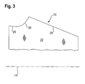
- the design of the cutting elements is shown in more detail in Fig. 3 in a side view.
- the cutting elements 22 each comprise a cutting edge 24, which in the present embodiment has three sections, namely a first rectilinear section 26, a second rectilinear section 28 and a curved section 30 therebetween.
- FIG. 3 also schematically illustrates the axis of rotation 14 of the machining tool 12 located. As can be seen in FIG. 3, in the present embodiment both the first straight section 26 and the second straight section 28 extend in a direction deviating from the axis of rotation 14.
- the angle of the intended for a face milling, second rectilinear portion 28 relative to the axis of rotation 14 corresponds to that angle which occupies the axis of rotation during face milling relative to the horizontal or relative to the workpiece conveying plane.
- FIG. 4 schematically shows different machining positions of the milling head 20 with respect to the workpiece 2 to be machined or the edge 2 'to be machined.
- Fig. 4 shows first a position of the milling head 20 and the associated cutting edge 24, which is designated by "P".
- the second straight section 28 (see Fig. 3) of the cutting edge 24 is used for face milling of the edge 2 '.
- the inclination of the rotation axis 14 relative to the horizontal corresponds to the inclination of the rotation axis 14 with respect to the first rectilinear portion 28.
- the flush trimming unit 10 (not shown in FIG. 4) can be pivoted about the pivot point 16 into the position "R" shown in FIG. In this position, the curved portion 30 of the cutting edge 24 is used to make a radius milling on the edge 2 '.
- the trimming assembly 10 may be further pivoted clockwise about the pivot point 16 with the associated milling head 20 to move the first rectilinear portion 26 of the cutting edge 24 to a position for chamfering the edge 2 'to bring.
- it can thus be changed by a mere pivoting of the flush trimming unit 10 and the milling tool 12 about the pivot point 16 around between the three Fräsbearbeitungsart face milling, radius milling and chamfering, possibly even during milling. In the course of this adjustment, no superimposed on the pivoting movement linear displacement of the milling tool is required.
Landscapes
- Engineering & Computer Science (AREA)
- Mechanical Engineering (AREA)
- Life Sciences & Earth Sciences (AREA)
- Wood Science & Technology (AREA)
- Forests & Forestry (AREA)
- Milling Processes (AREA)
- Milling, Drilling, And Turning Of Wood (AREA)
- Shovels (AREA)
Priority Applications (9)
| Application Number | Priority Date | Filing Date | Title |
|---|---|---|---|
| AT05024202T ATE385452T1 (de) | 2005-11-07 | 2005-11-07 | Kantenfräsmaschine |
| EP05024202A EP1782931B1 (fr) | 2005-11-07 | 2005-11-07 | Machine à fraiser les bords |
| PL05024202T PL1782931T3 (pl) | 2005-11-07 | 2005-11-07 | Frezarka krawędziowa |
| DE502005002773T DE502005002773D1 (de) | 2005-11-07 | 2005-11-07 | Kantenfräsmaschine |
| ES05024202T ES2302113T3 (es) | 2005-11-07 | 2005-11-07 | Maquina de biselar. |
| UAA200807659A UA94247C2 (en) | 2005-11-07 | 2006-07-11 | Edge trimming machine |
| CN2006800461533A CN101326037B (zh) | 2005-11-07 | 2006-11-07 | 修边机 |
| PCT/EP2006/010646 WO2007051649A1 (fr) | 2005-11-07 | 2006-11-07 | Machine a chanfreiner |
| RU2008122922/21A RU2416513C2 (ru) | 2005-11-07 | 2006-11-07 | Кромкофрезерный станок |
Applications Claiming Priority (1)
| Application Number | Priority Date | Filing Date | Title |
|---|---|---|---|
| EP05024202A EP1782931B1 (fr) | 2005-11-07 | 2005-11-07 | Machine à fraiser les bords |
Publications (2)
| Publication Number | Publication Date |
|---|---|
| EP1782931A1 true EP1782931A1 (fr) | 2007-05-09 |
| EP1782931B1 EP1782931B1 (fr) | 2008-02-06 |
Family
ID=36169094
Family Applications (1)
| Application Number | Title | Priority Date | Filing Date |
|---|---|---|---|
| EP05024202A Expired - Lifetime EP1782931B1 (fr) | 2005-11-07 | 2005-11-07 | Machine à fraiser les bords |
Country Status (9)
| Country | Link |
|---|---|
| EP (1) | EP1782931B1 (fr) |
| CN (1) | CN101326037B (fr) |
| AT (1) | ATE385452T1 (fr) |
| DE (1) | DE502005002773D1 (fr) |
| ES (1) | ES2302113T3 (fr) |
| PL (1) | PL1782931T3 (fr) |
| RU (1) | RU2416513C2 (fr) |
| UA (1) | UA94247C2 (fr) |
| WO (1) | WO2007051649A1 (fr) |
Cited By (4)
| Publication number | Priority date | Publication date | Assignee | Title |
|---|---|---|---|---|
| EP2792460A1 (fr) * | 2013-04-19 | 2014-10-22 | Homag Holzbearbeitungssysteme GmbH | Dispositif et procédé destinés à la finition des chants d'une pièce à usiner |
| CN106216746A (zh) * | 2016-08-26 | 2016-12-14 | 芜湖明特威工程机械有限公司 | 一种电磁平台式铣边机 |
| EP3124191A1 (fr) * | 2015-07-27 | 2017-02-01 | HOMAG GmbH | Groupe d'usinage pour l'usinage de pieces usinees en forme de plaque et procede d'usinage d'une piece usinee en forme de plaque |
| EP4534264A1 (fr) * | 2023-10-02 | 2025-04-09 | SCM Group S.p.A. | Unité de fraisage des chants et machine à plaquer les chants |
Families Citing this family (6)
| Publication number | Priority date | Publication date | Assignee | Title |
|---|---|---|---|---|
| ATE539862T1 (de) * | 2008-11-03 | 2012-01-15 | Brandt Kantentechnik Gmbh | Bearbeitungsaggregat |
| DE102010009525A1 (de) * | 2010-02-26 | 2011-09-01 | Homag Holzbearbeitungssysteme Ag | Vorrichtung zum Bearbeiten der Schmalflächen von bevorzugt plattenförmigen Werkstücken |
| CN101844246B (zh) * | 2010-06-10 | 2011-10-05 | 无锡华联科技集团有限公司 | 钢板铣削压辊调整机构 |
| DE102015221136B4 (de) * | 2014-11-03 | 2020-10-15 | Scm Group S.P.A. | Endbearbeitungsaggregat mit lageverstellbarer Kopiereinrichtung |
| CN117961567B (zh) * | 2024-03-28 | 2024-05-31 | 临汾金京泰钢结构有限公司 | 一种钢结构坡口加工用组合式加工设备 |
| CN118927371A (zh) * | 2024-08-13 | 2024-11-12 | 佛山市优禾优品机械科技有限公司 | 一种自动式免拉手封边机 |
Citations (6)
| Publication number | Priority date | Publication date | Assignee | Title |
|---|---|---|---|---|
| US2839107A (en) | 1957-03-25 | 1958-06-17 | Porter Cable Machine Co | Combination straight and bevel cutter |
| DE4030138A1 (de) * | 1990-09-24 | 1992-03-26 | Klessmann Ima Norte Maschfab | Maschine zum anbringen und buendigfraesen von kantenstreifen |
| JPH11188521A (ja) * | 1997-12-25 | 1999-07-13 | Shinx Ltd | 開先加工装置 |
| DE10124307C1 (de) | 2001-05-17 | 2002-06-13 | Klessmann Ima Gmbh Holzbearbei | Kantenfräsaggregat für eine programmgesteuerte Durchlaufmaschine |
| DE10229775C1 (de) * | 2002-07-03 | 2003-07-10 | Grotefeld Maschb & Vertriebs G | Kapp- und Kantenrundungs-Aggregat |
| EP1504837A1 (fr) * | 2003-08-06 | 2005-02-09 | Schiefergruben Magog GmbH & Co. KG | Méthode et dispositif pour l'usinage du contour extérieur d'une pièce |
Family Cites Families (3)
| Publication number | Priority date | Publication date | Assignee | Title |
|---|---|---|---|---|
| SU764873A1 (ru) * | 1978-10-30 | 1980-09-28 | Ленинградское Специальное Конструкторское Бюро Тяжелых И Уникальных Станков | Станок дл зачистки боковых кромок полос |
| SU1276490A1 (ru) * | 1985-01-17 | 1986-12-15 | Центральный Научно-Исследовательский Институт Механической Обработки Древесины "Союзнаучдревпром" | Фрезерно-обрезной станок |
| CN2488628Y (zh) * | 2001-07-17 | 2002-05-01 | 古知昀 | 一种改进的铣刀加工机的铣刀成形装置 |
-
2005
- 2005-11-07 PL PL05024202T patent/PL1782931T3/pl unknown
- 2005-11-07 ES ES05024202T patent/ES2302113T3/es not_active Expired - Lifetime
- 2005-11-07 AT AT05024202T patent/ATE385452T1/de active
- 2005-11-07 DE DE502005002773T patent/DE502005002773D1/de not_active Expired - Lifetime
- 2005-11-07 EP EP05024202A patent/EP1782931B1/fr not_active Expired - Lifetime
-
2006
- 2006-07-11 UA UAA200807659A patent/UA94247C2/uk unknown
- 2006-11-07 RU RU2008122922/21A patent/RU2416513C2/ru not_active IP Right Cessation
- 2006-11-07 CN CN2006800461533A patent/CN101326037B/zh not_active Expired - Fee Related
- 2006-11-07 WO PCT/EP2006/010646 patent/WO2007051649A1/fr not_active Ceased
Patent Citations (7)
| Publication number | Priority date | Publication date | Assignee | Title |
|---|---|---|---|---|
| US2839107A (en) | 1957-03-25 | 1958-06-17 | Porter Cable Machine Co | Combination straight and bevel cutter |
| DE4030138A1 (de) * | 1990-09-24 | 1992-03-26 | Klessmann Ima Norte Maschfab | Maschine zum anbringen und buendigfraesen von kantenstreifen |
| DE4030138C2 (fr) | 1990-09-24 | 1992-07-02 | Ima-Norte Maschinenfabriken Klessmann Gmbh & Co, 4830 Guetersloh, De | |
| JPH11188521A (ja) * | 1997-12-25 | 1999-07-13 | Shinx Ltd | 開先加工装置 |
| DE10124307C1 (de) | 2001-05-17 | 2002-06-13 | Klessmann Ima Gmbh Holzbearbei | Kantenfräsaggregat für eine programmgesteuerte Durchlaufmaschine |
| DE10229775C1 (de) * | 2002-07-03 | 2003-07-10 | Grotefeld Maschb & Vertriebs G | Kapp- und Kantenrundungs-Aggregat |
| EP1504837A1 (fr) * | 2003-08-06 | 2005-02-09 | Schiefergruben Magog GmbH & Co. KG | Méthode et dispositif pour l'usinage du contour extérieur d'une pièce |
Non-Patent Citations (1)
| Title |
|---|
| PATENT ABSTRACTS OF JAPAN vol. 1999, no. 12 29 October 1999 (1999-10-29) * |
Cited By (4)
| Publication number | Priority date | Publication date | Assignee | Title |
|---|---|---|---|---|
| EP2792460A1 (fr) * | 2013-04-19 | 2014-10-22 | Homag Holzbearbeitungssysteme GmbH | Dispositif et procédé destinés à la finition des chants d'une pièce à usiner |
| EP3124191A1 (fr) * | 2015-07-27 | 2017-02-01 | HOMAG GmbH | Groupe d'usinage pour l'usinage de pieces usinees en forme de plaque et procede d'usinage d'une piece usinee en forme de plaque |
| CN106216746A (zh) * | 2016-08-26 | 2016-12-14 | 芜湖明特威工程机械有限公司 | 一种电磁平台式铣边机 |
| EP4534264A1 (fr) * | 2023-10-02 | 2025-04-09 | SCM Group S.p.A. | Unité de fraisage des chants et machine à plaquer les chants |
Also Published As
| Publication number | Publication date |
|---|---|
| UA94247C2 (en) | 2011-04-26 |
| WO2007051649A1 (fr) | 2007-05-10 |
| CN101326037A (zh) | 2008-12-17 |
| CN101326037B (zh) | 2012-09-26 |
| RU2416513C2 (ru) | 2011-04-20 |
| DE502005002773D1 (de) | 2008-03-20 |
| ES2302113T3 (es) | 2008-07-01 |
| RU2008122922A (ru) | 2009-12-20 |
| ATE385452T1 (de) | 2008-02-15 |
| EP1782931B1 (fr) | 2008-02-06 |
| PL1782931T3 (pl) | 2008-07-31 |
Similar Documents
| Publication | Publication Date | Title |
|---|---|---|
| EP2392438B1 (fr) | Dispositif de traitement | |
| EP2181816B1 (fr) | Appareil d'usinage | |
| EP2087971A2 (fr) | Dispositif de coupe | |
| EP1122042B1 (fr) | Procédé et appareil pour fraiser une rainure dans un élément sous forme de plaque | |
| EP1782931B1 (fr) | Machine à fraiser les bords | |
| EP3957448B1 (fr) | Dispositif couteau circulaire | |
| EP0602308B1 (fr) | Dispositif pour travailler les cÔtés de pièces en forme de plaques alimentées de façon continue | |
| DE102006007171B4 (de) | Vorrichtung zum Bearbeiten von Eckverbindungen verschweißter Kunststoffprofile und Verfahren zum Bearbeiten von Eckverbindungen | |
| EP1837110B1 (fr) | Réglette à butée avec un guidage longitudinal double et mobile | |
| DE102005020485B3 (de) | Bündigfräs- und Abziehaggregat | |
| DE2315719A1 (de) | Vorrichtung zum spanabhebenden bearbeiten der kanten von werkstueckplatten | |
| EP2147760A2 (fr) | Centre de répartition de plaques destiné au traitement complet de pièces usinées en forme de plaques, notamment des éléments de meuble | |
| EP0813941B2 (fr) | Machine-outil pour l'usinage de pièces allongées | |
| EP2185330A1 (fr) | Machine à fraiser sur une face et unité d'alésage à utiliser avec une telle machine | |
| DE2415006C3 (de) | Verfahren zur Herstellung von Fensterrahmen mit Glashalteleiste aus Holz und Vorrichtung zur Durchführung des Verfahrens | |
| EP2433731B1 (fr) | Installation de répartition de plaques pour répartir des pièces en forme de plaques | |
| EP0744255A2 (fr) | Dispositif pour découper des troncs d'arbres et tête de fraisage pour ce dispositif | |
| AT10778U1 (de) | Bearbeitungsaggregat einer durchlaufmaschine, insbesondere fügeaggregat | |
| EP0715564B1 (fr) | Scie oscillatoire a onglet pourvue d'un etabli | |
| DE202007017278U1 (de) | Tragbare Maschine zur Eckenbearbeitung | |
| EP1439044B1 (fr) | Une machine outil à bois avec un système de butée | |
| EP1925412B1 (fr) | Unité d'usinage de chants | |
| DE19905414C2 (de) | Vorrichtung zum Schneiden und Einkerben von Profilen | |
| DE10208071B4 (de) | Parallelanschlagsvorrichtung für einen Sägetisch | |
| DE19721521C2 (de) | Numerisch gesteuerte Zapfenschneidmaschine |
Legal Events
| Date | Code | Title | Description |
|---|---|---|---|
| PUAI | Public reference made under article 153(3) epc to a published international application that has entered the european phase |
Free format text: ORIGINAL CODE: 0009012 |
|
| 17P | Request for examination filed |
Effective date: 20060816 |
|
| AK | Designated contracting states |
Kind code of ref document: A1 Designated state(s): AT BE BG CH CY CZ DE DK EE ES FI FR GB GR HU IE IS IT LI LT LU LV MC NL PL PT RO SE SI SK TR |
|
| AX | Request for extension of the european patent |
Extension state: AL BA HR MK YU |
|
| GRAP | Despatch of communication of intention to grant a patent |
Free format text: ORIGINAL CODE: EPIDOSNIGR1 |
|
| GRAS | Grant fee paid |
Free format text: ORIGINAL CODE: EPIDOSNIGR3 |
|
| GRAA | (expected) grant |
Free format text: ORIGINAL CODE: 0009210 |
|
| AKX | Designation fees paid |
Designated state(s): AT BE BG CH CY CZ DE DK EE ES FI FR GB GR HU IE IS IT LI LT LU LV MC NL PL PT RO SE SI SK TR |
|
| AK | Designated contracting states |
Kind code of ref document: B1 Designated state(s): AT BE BG CH CY CZ DE DK EE ES FI FR GB GR HU IE IS IT LI LT LU LV MC NL PL PT RO SE SI SK TR |
|
| REG | Reference to a national code |
Ref country code: GB Ref legal event code: FG4D Free format text: NOT ENGLISH |
|
| REG | Reference to a national code |
Ref country code: CH Ref legal event code: EP |
|
| REG | Reference to a national code |
Ref country code: IE Ref legal event code: FG4D Free format text: LANGUAGE OF EP DOCUMENT: GERMAN |
|
| REF | Corresponds to: |
Ref document number: 502005002773 Country of ref document: DE Date of ref document: 20080320 Kind code of ref document: P |
|
| REG | Reference to a national code |
Ref country code: ES Ref legal event code: FG2A Ref document number: 2302113 Country of ref document: ES Kind code of ref document: T3 |
|
| PG25 | Lapsed in a contracting state [announced via postgrant information from national office to epo] |
Ref country code: FI Free format text: LAPSE BECAUSE OF FAILURE TO SUBMIT A TRANSLATION OF THE DESCRIPTION OR TO PAY THE FEE WITHIN THE PRESCRIBED TIME-LIMIT Effective date: 20080206 Ref country code: IS Free format text: LAPSE BECAUSE OF FAILURE TO SUBMIT A TRANSLATION OF THE DESCRIPTION OR TO PAY THE FEE WITHIN THE PRESCRIBED TIME-LIMIT Effective date: 20080606 |
|
| REG | Reference to a national code |
Ref country code: PL Ref legal event code: T3 |
|
| NLV1 | Nl: lapsed or annulled due to failure to fulfill the requirements of art. 29p and 29m of the patents act | ||
| PG25 | Lapsed in a contracting state [announced via postgrant information from national office to epo] |
Ref country code: LV Free format text: LAPSE BECAUSE OF FAILURE TO SUBMIT A TRANSLATION OF THE DESCRIPTION OR TO PAY THE FEE WITHIN THE PRESCRIBED TIME-LIMIT Effective date: 20080206 Ref country code: SI Free format text: LAPSE BECAUSE OF FAILURE TO SUBMIT A TRANSLATION OF THE DESCRIPTION OR TO PAY THE FEE WITHIN THE PRESCRIBED TIME-LIMIT Effective date: 20080206 |
|
| REG | Reference to a national code |
Ref country code: IE Ref legal event code: FD4D |
|
| PG25 | Lapsed in a contracting state [announced via postgrant information from national office to epo] |
Ref country code: SK Free format text: LAPSE BECAUSE OF FAILURE TO SUBMIT A TRANSLATION OF THE DESCRIPTION OR TO PAY THE FEE WITHIN THE PRESCRIBED TIME-LIMIT Effective date: 20080206 Ref country code: NL Free format text: LAPSE BECAUSE OF FAILURE TO SUBMIT A TRANSLATION OF THE DESCRIPTION OR TO PAY THE FEE WITHIN THE PRESCRIBED TIME-LIMIT Effective date: 20080206 Ref country code: CZ Free format text: LAPSE BECAUSE OF FAILURE TO SUBMIT A TRANSLATION OF THE DESCRIPTION OR TO PAY THE FEE WITHIN THE PRESCRIBED TIME-LIMIT Effective date: 20080206 Ref country code: IE Free format text: LAPSE BECAUSE OF FAILURE TO SUBMIT A TRANSLATION OF THE DESCRIPTION OR TO PAY THE FEE WITHIN THE PRESCRIBED TIME-LIMIT Effective date: 20080206 Ref country code: PT Free format text: LAPSE BECAUSE OF FAILURE TO SUBMIT A TRANSLATION OF THE DESCRIPTION OR TO PAY THE FEE WITHIN THE PRESCRIBED TIME-LIMIT Effective date: 20080707 Ref country code: SE Free format text: LAPSE BECAUSE OF FAILURE TO SUBMIT A TRANSLATION OF THE DESCRIPTION OR TO PAY THE FEE WITHIN THE PRESCRIBED TIME-LIMIT Effective date: 20080506 Ref country code: DK Free format text: LAPSE BECAUSE OF FAILURE TO SUBMIT A TRANSLATION OF THE DESCRIPTION OR TO PAY THE FEE WITHIN THE PRESCRIBED TIME-LIMIT Effective date: 20080206 |
|
| EN | Fr: translation not filed | ||
| PG25 | Lapsed in a contracting state [announced via postgrant information from national office to epo] |
Ref country code: RO Free format text: LAPSE BECAUSE OF FAILURE TO SUBMIT A TRANSLATION OF THE DESCRIPTION OR TO PAY THE FEE WITHIN THE PRESCRIBED TIME-LIMIT Effective date: 20080206 |
|
| PLBE | No opposition filed within time limit |
Free format text: ORIGINAL CODE: 0009261 |
|
| STAA | Information on the status of an ep patent application or granted ep patent |
Free format text: STATUS: NO OPPOSITION FILED WITHIN TIME LIMIT |
|
| 26N | No opposition filed |
Effective date: 20081107 |
|
| PG25 | Lapsed in a contracting state [announced via postgrant information from national office to epo] |
Ref country code: LT Free format text: LAPSE BECAUSE OF FAILURE TO SUBMIT A TRANSLATION OF THE DESCRIPTION OR TO PAY THE FEE WITHIN THE PRESCRIBED TIME-LIMIT Effective date: 20080206 |
|
| PG25 | Lapsed in a contracting state [announced via postgrant information from national office to epo] |
Ref country code: EE Free format text: LAPSE BECAUSE OF FAILURE TO SUBMIT A TRANSLATION OF THE DESCRIPTION OR TO PAY THE FEE WITHIN THE PRESCRIBED TIME-LIMIT Effective date: 20080206 Ref country code: FR Free format text: LAPSE BECAUSE OF FAILURE TO SUBMIT A TRANSLATION OF THE DESCRIPTION OR TO PAY THE FEE WITHIN THE PRESCRIBED TIME-LIMIT Effective date: 20081128 Ref country code: BG Free format text: LAPSE BECAUSE OF FAILURE TO SUBMIT A TRANSLATION OF THE DESCRIPTION OR TO PAY THE FEE WITHIN THE PRESCRIBED TIME-LIMIT Effective date: 20080506 |
|
| BERE | Be: lapsed |
Owner name: BRANDT KANTENTECHNIK G.M.B.H. Effective date: 20081130 |
|
| PG25 | Lapsed in a contracting state [announced via postgrant information from national office to epo] |
Ref country code: MC Free format text: LAPSE BECAUSE OF NON-PAYMENT OF DUE FEES Effective date: 20081130 |
|
| PG25 | Lapsed in a contracting state [announced via postgrant information from national office to epo] |
Ref country code: CY Free format text: LAPSE BECAUSE OF FAILURE TO SUBMIT A TRANSLATION OF THE DESCRIPTION OR TO PAY THE FEE WITHIN THE PRESCRIBED TIME-LIMIT Effective date: 20080206 |
|
| PG25 | Lapsed in a contracting state [announced via postgrant information from national office to epo] |
Ref country code: BE Free format text: LAPSE BECAUSE OF NON-PAYMENT OF DUE FEES Effective date: 20081130 |
|
| REG | Reference to a national code |
Ref country code: CH Ref legal event code: PL |
|
| GBPC | Gb: european patent ceased through non-payment of renewal fee |
Effective date: 20091107 |
|
| PG25 | Lapsed in a contracting state [announced via postgrant information from national office to epo] |
Ref country code: HU Free format text: LAPSE BECAUSE OF FAILURE TO SUBMIT A TRANSLATION OF THE DESCRIPTION OR TO PAY THE FEE WITHIN THE PRESCRIBED TIME-LIMIT Effective date: 20080807 Ref country code: LU Free format text: LAPSE BECAUSE OF NON-PAYMENT OF DUE FEES Effective date: 20081107 |
|
| PG25 | Lapsed in a contracting state [announced via postgrant information from national office to epo] |
Ref country code: GR Free format text: LAPSE BECAUSE OF FAILURE TO SUBMIT A TRANSLATION OF THE DESCRIPTION OR TO PAY THE FEE WITHIN THE PRESCRIBED TIME-LIMIT Effective date: 20080507 Ref country code: LI Free format text: LAPSE BECAUSE OF NON-PAYMENT OF DUE FEES Effective date: 20091130 Ref country code: CH Free format text: LAPSE BECAUSE OF NON-PAYMENT OF DUE FEES Effective date: 20091130 |
|
| PG25 | Lapsed in a contracting state [announced via postgrant information from national office to epo] |
Ref country code: GB Free format text: LAPSE BECAUSE OF NON-PAYMENT OF DUE FEES Effective date: 20091107 |
|
| PGFP | Annual fee paid to national office [announced via postgrant information from national office to epo] |
Ref country code: PL Payment date: 20101013 Year of fee payment: 6 |
|
| PGFP | Annual fee paid to national office [announced via postgrant information from national office to epo] |
Ref country code: TR Payment date: 20101101 Year of fee payment: 6 |
|
| PG25 | Lapsed in a contracting state [announced via postgrant information from national office to epo] |
Ref country code: PL Free format text: LAPSE BECAUSE OF NON-PAYMENT OF DUE FEES Effective date: 20111107 |
|
| REG | Reference to a national code |
Ref country code: PL Ref legal event code: LAPE |
|
| PG25 | Lapsed in a contracting state [announced via postgrant information from national office to epo] |
Ref country code: TR Free format text: LAPSE BECAUSE OF NON-PAYMENT OF DUE FEES Effective date: 20111107 |
|
| PGFP | Annual fee paid to national office [announced via postgrant information from national office to epo] |
Ref country code: ES Payment date: 20191202 Year of fee payment: 15 |
|
| REG | Reference to a national code |
Ref country code: ES Ref legal event code: FD2A Effective date: 20220131 |
|
| PG25 | Lapsed in a contracting state [announced via postgrant information from national office to epo] |
Ref country code: ES Free format text: LAPSE BECAUSE OF NON-PAYMENT OF DUE FEES Effective date: 20201108 |
|
| PGFP | Annual fee paid to national office [announced via postgrant information from national office to epo] |
Ref country code: IT Payment date: 20221128 Year of fee payment: 18 Ref country code: DE Payment date: 20220518 Year of fee payment: 18 Ref country code: AT Payment date: 20221108 Year of fee payment: 18 |
|
| P01 | Opt-out of the competence of the unified patent court (upc) registered |
Effective date: 20230529 |
|
| REG | Reference to a national code |
Ref country code: DE Ref legal event code: R119 Ref document number: 502005002773 Country of ref document: DE |
|
| REG | Reference to a national code |
Ref country code: AT Ref legal event code: MM01 Ref document number: 385452 Country of ref document: AT Kind code of ref document: T Effective date: 20231107 |
|
| PG25 | Lapsed in a contracting state [announced via postgrant information from national office to epo] |
Ref country code: AT Free format text: LAPSE BECAUSE OF NON-PAYMENT OF DUE FEES Effective date: 20231107 |
|
| PG25 | Lapsed in a contracting state [announced via postgrant information from national office to epo] |
Ref country code: AT Free format text: LAPSE BECAUSE OF NON-PAYMENT OF DUE FEES Effective date: 20231107 |
|
| PG25 | Lapsed in a contracting state [announced via postgrant information from national office to epo] |
Ref country code: DE Free format text: LAPSE BECAUSE OF NON-PAYMENT OF DUE FEES Effective date: 20240601 |
|
| PG25 | Lapsed in a contracting state [announced via postgrant information from national office to epo] |
Ref country code: DE Free format text: LAPSE BECAUSE OF NON-PAYMENT OF DUE FEES Effective date: 20240601 |
|
| PG25 | Lapsed in a contracting state [announced via postgrant information from national office to epo] |
Ref country code: IT Free format text: LAPSE BECAUSE OF NON-PAYMENT OF DUE FEES Effective date: 20231107 |
|
| PG25 | Lapsed in a contracting state [announced via postgrant information from national office to epo] |
Ref country code: IT Free format text: LAPSE BECAUSE OF NON-PAYMENT OF DUE FEES Effective date: 20231107 |