EP1785220B1 - Verfahren und Vorrichtung zur Reparatur beschädigter Paletten - Google Patents
Verfahren und Vorrichtung zur Reparatur beschädigter Paletten Download PDFInfo
- Publication number
- EP1785220B1 EP1785220B1 EP06405472A EP06405472A EP1785220B1 EP 1785220 B1 EP1785220 B1 EP 1785220B1 EP 06405472 A EP06405472 A EP 06405472A EP 06405472 A EP06405472 A EP 06405472A EP 1785220 B1 EP1785220 B1 EP 1785220B1
- Authority
- EP
- European Patent Office
- Prior art keywords
- pallet
- connecting elements
- station
- set forth
- new
- Prior art date
- Legal status (The legal status is an assumption and is not a legal conclusion. Google has not performed a legal analysis and makes no representation as to the accuracy of the status listed.)
- Active
Links
Images

Classifications
-
- B—PERFORMING OPERATIONS; TRANSPORTING
- B25—HAND TOOLS; PORTABLE POWER-DRIVEN TOOLS; MANIPULATORS
- B25B—TOOLS OR BENCH DEVICES NOT OTHERWISE PROVIDED FOR, FOR FASTENING, CONNECTING, DISENGAGING, OR HOLDING
- B25B27/00—Hand tools, specially adapted for fitting together or separating parts or objects whether or not involving some deformation, not otherwise provided for
- B25B27/02—Hand tools, specially adapted for fitting together or separating parts or objects whether or not involving some deformation, not otherwise provided for for connecting objects by press fit or detaching same
-
- B—PERFORMING OPERATIONS; TRANSPORTING
- B23—MACHINE TOOLS; METAL-WORKING NOT OTHERWISE PROVIDED FOR
- B23P—METAL-WORKING NOT OTHERWISE PROVIDED FOR; COMBINED OPERATIONS; UNIVERSAL MACHINE TOOLS
- B23P19/00—Machines for simply fitting together or separating metal parts or objects, or metal and non-metal parts, whether or not involving some deformation; Tools or devices therefor so far as not provided for in other classes
- B23P19/04—Machines for simply fitting together or separating metal parts or objects, or metal and non-metal parts, whether or not involving some deformation; Tools or devices therefor so far as not provided for in other classes for assembling or disassembling parts
- B23P19/041—Machines for simply fitting together or separating metal parts or objects, or metal and non-metal parts, whether or not involving some deformation; Tools or devices therefor so far as not provided for in other classes for assembling or disassembling parts for disassembling pallets
-
- B—PERFORMING OPERATIONS; TRANSPORTING
- B25—HAND TOOLS; PORTABLE POWER-DRIVEN TOOLS; MANIPULATORS
- B25B—TOOLS OR BENCH DEVICES NOT OTHERWISE PROVIDED FOR, FOR FASTENING, CONNECTING, DISENGAGING, OR HOLDING
- B25B27/00—Hand tools, specially adapted for fitting together or separating parts or objects whether or not involving some deformation, not otherwise provided for
- B25B27/14—Hand tools, specially adapted for fitting together or separating parts or objects whether or not involving some deformation, not otherwise provided for for assembling objects other than by press fit or detaching same
-
- B—PERFORMING OPERATIONS; TRANSPORTING
- B27—WORKING OR PRESERVING WOOD OR SIMILAR MATERIAL; NAILING OR STAPLING MACHINES IN GENERAL
- B27M—WORKING OF WOOD NOT PROVIDED FOR IN SUBCLASSES B27B - B27L; MANUFACTURE OF SPECIFIC WOODEN ARTICLES
- B27M3/00—Manufacture or reconditioning of specific semi-finished or finished articles
- B27M3/0013—Manufacture or reconditioning of specific semi-finished or finished articles of composite or compound articles
- B27M3/0073—Manufacture or reconditioning of specific semi-finished or finished articles of composite or compound articles characterised by nailing, stapling or screwing connections
-
- Y—GENERAL TAGGING OF NEW TECHNOLOGICAL DEVELOPMENTS; GENERAL TAGGING OF CROSS-SECTIONAL TECHNOLOGIES SPANNING OVER SEVERAL SECTIONS OF THE IPC; TECHNICAL SUBJECTS COVERED BY FORMER USPC CROSS-REFERENCE ART COLLECTIONS [XRACs] AND DIGESTS
- Y10—TECHNICAL SUBJECTS COVERED BY FORMER USPC
- Y10T—TECHNICAL SUBJECTS COVERED BY FORMER US CLASSIFICATION
- Y10T29/00—Metal working
- Y10T29/49—Method of mechanical manufacture
- Y10T29/49616—Structural member making
- Y10T29/49623—Static structure, e.g., a building component
- Y10T29/49625—Openwork, e.g., a truss, joist, frame, lattice-type or box beam
-
- Y—GENERAL TAGGING OF NEW TECHNOLOGICAL DEVELOPMENTS; GENERAL TAGGING OF CROSS-SECTIONAL TECHNOLOGIES SPANNING OVER SEVERAL SECTIONS OF THE IPC; TECHNICAL SUBJECTS COVERED BY FORMER USPC CROSS-REFERENCE ART COLLECTIONS [XRACs] AND DIGESTS
- Y10—TECHNICAL SUBJECTS COVERED BY FORMER USPC
- Y10T—TECHNICAL SUBJECTS COVERED BY FORMER US CLASSIFICATION
- Y10T29/00—Metal working
- Y10T29/49—Method of mechanical manufacture
- Y10T29/49718—Repairing
-
- Y—GENERAL TAGGING OF NEW TECHNOLOGICAL DEVELOPMENTS; GENERAL TAGGING OF CROSS-SECTIONAL TECHNOLOGIES SPANNING OVER SEVERAL SECTIONS OF THE IPC; TECHNICAL SUBJECTS COVERED BY FORMER USPC CROSS-REFERENCE ART COLLECTIONS [XRACs] AND DIGESTS
- Y10—TECHNICAL SUBJECTS COVERED BY FORMER USPC
- Y10T—TECHNICAL SUBJECTS COVERED BY FORMER US CLASSIFICATION
- Y10T29/00—Metal working
- Y10T29/49—Method of mechanical manufacture
- Y10T29/49718—Repairing
- Y10T29/49721—Repairing with disassembling
-
- Y—GENERAL TAGGING OF NEW TECHNOLOGICAL DEVELOPMENTS; GENERAL TAGGING OF CROSS-SECTIONAL TECHNOLOGIES SPANNING OVER SEVERAL SECTIONS OF THE IPC; TECHNICAL SUBJECTS COVERED BY FORMER USPC CROSS-REFERENCE ART COLLECTIONS [XRACs] AND DIGESTS
- Y10—TECHNICAL SUBJECTS COVERED BY FORMER USPC
- Y10T—TECHNICAL SUBJECTS COVERED BY FORMER US CLASSIFICATION
- Y10T29/00—Metal working
- Y10T29/49—Method of mechanical manufacture
- Y10T29/49718—Repairing
- Y10T29/49721—Repairing with disassembling
- Y10T29/49723—Repairing with disassembling including reconditioning of part
-
- Y—GENERAL TAGGING OF NEW TECHNOLOGICAL DEVELOPMENTS; GENERAL TAGGING OF CROSS-SECTIONAL TECHNOLOGIES SPANNING OVER SEVERAL SECTIONS OF THE IPC; TECHNICAL SUBJECTS COVERED BY FORMER USPC CROSS-REFERENCE ART COLLECTIONS [XRACs] AND DIGESTS
- Y10—TECHNICAL SUBJECTS COVERED BY FORMER USPC
- Y10T—TECHNICAL SUBJECTS COVERED BY FORMER US CLASSIFICATION
- Y10T29/00—Metal working
- Y10T29/49—Method of mechanical manufacture
- Y10T29/49718—Repairing
- Y10T29/49721—Repairing with disassembling
- Y10T29/49723—Repairing with disassembling including reconditioning of part
- Y10T29/49725—Repairing with disassembling including reconditioning of part by shaping
- Y10T29/49726—Removing material
-
- Y—GENERAL TAGGING OF NEW TECHNOLOGICAL DEVELOPMENTS; GENERAL TAGGING OF CROSS-SECTIONAL TECHNOLOGIES SPANNING OVER SEVERAL SECTIONS OF THE IPC; TECHNICAL SUBJECTS COVERED BY FORMER USPC CROSS-REFERENCE ART COLLECTIONS [XRACs] AND DIGESTS
- Y10—TECHNICAL SUBJECTS COVERED BY FORMER USPC
- Y10T—TECHNICAL SUBJECTS COVERED BY FORMER US CLASSIFICATION
- Y10T29/00—Metal working
- Y10T29/49—Method of mechanical manufacture
- Y10T29/49718—Repairing
- Y10T29/49721—Repairing with disassembling
- Y10T29/4973—Replacing of defective part
-
- Y—GENERAL TAGGING OF NEW TECHNOLOGICAL DEVELOPMENTS; GENERAL TAGGING OF CROSS-SECTIONAL TECHNOLOGIES SPANNING OVER SEVERAL SECTIONS OF THE IPC; TECHNICAL SUBJECTS COVERED BY FORMER USPC CROSS-REFERENCE ART COLLECTIONS [XRACs] AND DIGESTS
- Y10—TECHNICAL SUBJECTS COVERED BY FORMER USPC
- Y10T—TECHNICAL SUBJECTS COVERED BY FORMER US CLASSIFICATION
- Y10T29/00—Metal working
- Y10T29/49—Method of mechanical manufacture
- Y10T29/49764—Method of mechanical manufacture with testing or indicating
- Y10T29/49771—Quantitative measuring or gauging
-
- Y—GENERAL TAGGING OF NEW TECHNOLOGICAL DEVELOPMENTS; GENERAL TAGGING OF CROSS-SECTIONAL TECHNOLOGIES SPANNING OVER SEVERAL SECTIONS OF THE IPC; TECHNICAL SUBJECTS COVERED BY FORMER USPC CROSS-REFERENCE ART COLLECTIONS [XRACs] AND DIGESTS
- Y10—TECHNICAL SUBJECTS COVERED BY FORMER USPC
- Y10T—TECHNICAL SUBJECTS COVERED BY FORMER US CLASSIFICATION
- Y10T29/00—Metal working
- Y10T29/49—Method of mechanical manufacture
- Y10T29/49815—Disassembling
-
- Y—GENERAL TAGGING OF NEW TECHNOLOGICAL DEVELOPMENTS; GENERAL TAGGING OF CROSS-SECTIONAL TECHNOLOGIES SPANNING OVER SEVERAL SECTIONS OF THE IPC; TECHNICAL SUBJECTS COVERED BY FORMER USPC CROSS-REFERENCE ART COLLECTIONS [XRACs] AND DIGESTS
- Y10—TECHNICAL SUBJECTS COVERED BY FORMER USPC
- Y10T—TECHNICAL SUBJECTS COVERED BY FORMER US CLASSIFICATION
- Y10T29/00—Metal working
- Y10T29/49—Method of mechanical manufacture
- Y10T29/49815—Disassembling
- Y10T29/49821—Disassembling by altering or destroying work part or connector
-
- Y—GENERAL TAGGING OF NEW TECHNOLOGICAL DEVELOPMENTS; GENERAL TAGGING OF CROSS-SECTIONAL TECHNOLOGIES SPANNING OVER SEVERAL SECTIONS OF THE IPC; TECHNICAL SUBJECTS COVERED BY FORMER USPC CROSS-REFERENCE ART COLLECTIONS [XRACs] AND DIGESTS
- Y10—TECHNICAL SUBJECTS COVERED BY FORMER USPC
- Y10T—TECHNICAL SUBJECTS COVERED BY FORMER US CLASSIFICATION
- Y10T29/00—Metal working
- Y10T29/53—Means to assemble or disassemble
- Y10T29/53313—Means to interrelatedly feed plural work parts from plural sources without manual intervention
- Y10T29/53317—Box or pallet assembly means
-
- Y—GENERAL TAGGING OF NEW TECHNOLOGICAL DEVELOPMENTS; GENERAL TAGGING OF CROSS-SECTIONAL TECHNOLOGIES SPANNING OVER SEVERAL SECTIONS OF THE IPC; TECHNICAL SUBJECTS COVERED BY FORMER USPC CROSS-REFERENCE ART COLLECTIONS [XRACs] AND DIGESTS
- Y10—TECHNICAL SUBJECTS COVERED BY FORMER USPC
- Y10T—TECHNICAL SUBJECTS COVERED BY FORMER US CLASSIFICATION
- Y10T29/00—Metal working
- Y10T29/53—Means to assemble or disassemble
- Y10T29/53961—Means to assemble or disassemble with work-holder for assembly
Definitions
- the present invention relates to a method for repairing damaged pallets according to the preamble of claim 1, and to an arrangement for carrying out the method according to the preamble of claim 10.
- From the DE-A-43 08 580 is a method and a device for repairing damaged pallets known.
- the damaged pallet is positioned and fixed in a turned up position on a machine table. Thereafter, the damaged supporting blocks and slats are separated by means of a separating device which is slidably mounted in three coordinate axes.
- the separating device has a machine head, which is provided with a vertical drive shaft, on the end of a rotating circular saw blade is mounted.
- the diameter of the circular saw blade is chosen to be smaller than the clear width between the longitudinal rows of supporting blocks. As a result, the circular saw blade can be introduced between the rows of supporting blocks running in the longitudinal direction so that the damaged parts of the pallet can be sawn out in a targeted manner.
- the fasteners - nail - are severed.
- the pallet is fed to a loading and fastening station, where the parts to be replaced are fed to the appropriate location and positioned.
- the actual attachment of the new parts is carried out by means of two nail devices that simultaneously hammer in nails from above and below.
- a method and apparatus for repairing damaged wooden pallets is known.
- the damaged boards and / or skids are separated from the pallet to be repaired.
- the new parts are aligned on the pallet and then nailed.
- the pallets are pressed, so that possibly protruding nails and not quite fitting boards are pressed.
- the apparatus for performing these method steps comprises a feed conveyor for feeding the pallets, a destacker for separating the pallets, a dismantling station for selectively separating the defective parts, a loading station for replacing the defective parts, a centering and nailing station for fixing the replaced parts and a press station for pressing on protruding nails and not quite adjacent boards.
- the DE-A-198 22 229 forms the closest prior art and discloses a method and an arrangement according to the preamble of claim 1 and 10, respectively.
- the invention aims to provide a method and an arrangement for repairing damaged pallets in such a way that the pallets can be repaired quickly, easily and reliably.
- the basic idea of the invention is to be seen in the fact that in a first step, the connecting elements of the pallet parts to be replaced are severed, that subsequently both the new pallet parts as well as the partially dismantled pallet are transferred to a fastening station, and then by attaching the new pallet parts in the attachment station be fixed by new fasteners on the pallet by all new fasteners are mounted from the top of the pallet ago. So that the fasteners can be mounted only from the top of the pallet ago, the pallet is preferably repaired by the modular exchange of pallet parts, with a defective floor board always in runner shape, ie is removed along with the three associated Mattsklötzen. The new skid can then be attached relatively easily from the top of the pallet.
- the location of the located in the top board above the newly installed runner connecting elements is detected and stored, so that afterwards the new fasteners can be added offset to the existing fasteners, which is an important condition for a safe and durable Reliable attachment of the new runner is because in this way the risk is eliminated that the new fasteners are inclined obliquely when mounting through the existing fasteners or even kinked or broken off.
- an automatic test station is also preferably provided with sensors for detecting the position of located in the cover board connecting elements.
- the Fig. 1 shows a pallet 1 in a perspective view.
- the Euro-pallet 1 shown here is made exclusively of wooden parts and consists of five longitudinally extending cover boards 2a-2e, three transversely arranged transverse boards 3a-3c and three extending in the longitudinal direction floorboards 4a-4c. Each floorboard 4a is connected to the three transverse boards 3a-3c by means of three connecting blocks 5a-5c.
- the two inner cover boards 2b, 2d are narrower than the two outer and the middle cover board 2a, 2c, 2e.
- the individual parts of the pallets are connected to one another by means of connecting elements in the form of nails 6, wherein nails are hammered in both from the upper side and from the lower side.
- the nails 6 taken from above connect the respective cover board 2a-2e to the underlying transverse board 3a-3e and the associated connecting block, while the nails hammered from below connect the respective floor board 4a-4c to the associated connecting block. That is, a nail hammered from above penetrates both the respective deck and the transverse board and is anchored in the connecting block, while a nail hammered from below the penetrates respective floor board and anchored in the corresponding connection block.
- the nails hammered in from below are not apparent from this illustration.
- the Fig. 2 shows a pallet 1 in partially dismounted state.
- a defective part such as a damaged or broken deck board 2d of the pallet 1
- the corresponding nails are severed. This is done by the nails connecting this cover board 2d with the pallet 1 directly above the three cross boards 3a-3c are severed.
- a band saw blade is used, which is narrower than the distance between two adjacent cover boards 2a-2b; 2b-2c; 2c-2d, 2d-2e ( Fig.1 ), but longer than the respective deck board.
- the plane in which the saw blade moves to sever the nails of the respective cover board 2d is schematically indicated and designated E1.
- a defective bottom board 4a or a defective connection block is preferably not removed on its own, but rather as a module in the form of a runner 8; i.e. the respective floorboard is always removed together with the three associated connection blocks 5a-5c.
- the saw blade is moved in a plane E2, in which the nails are severed directly below the respective cross-board 3a-3c. Again, care is taken to ensure that when cutting the fasteners remaining on the pallet cross boards are not damaged.
- the modular removal of a runner 8 has the advantage that the replacement runner can be attached to it from the top of the pallet, as will be explained in more detail below.
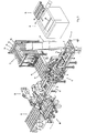
- Fig. 3 shows a plan view of the arrangement for repairing damaged pallets, which is hereinafter referred to as a pallet repair facility.
- This pallet repair system consists essentially of a dismantling station 10, an insertion station 11, a test station 12, a transfer station 13, a conveyor 14, a spare parts magazine 15, a spare part transfer station 16, a spare part conveyor 17, a fastening station designed as a nail station 18, a discharge conveyor 19, a robot 20, and a control unit 21 ,
- a pallet 1a to be repaired can be seen, which is provided by way of example with a defective cover board 2b and a defective skid 8.
- the bottom board 4a of the skid 8 is defective.
- the function of the pallet repair system is as follows:
- the defective pallet 1a is first processed in the schematically illustrated dismantling station 10 by dismantling the defective parts of the pallet 1a, in the present example the cover board 2b and the skid 8.
- the disassembly of the pallet 1a is carried out in the manner described above, by first the fasteners -nails- the cover board 2b and the runner in the previously described levels E1 and E2 ( Fig. 2 ) is severed by means of a band saw blade 23 and the corresponding parts 2b, 8 are removed afterwards.
- the band saw blade 23 is height adjustable at least in two stages.
- the lower step is chosen so that when feeding a pallet, the nails are cut directly below a cross-board, while in the upper stage, the nails are severed immediately above a cross-board.
- the steps are chosen such that at best the part to be removed is damaged or sawed by the saw blade, but not the parts remaining on the pallet, namely the transverse boards.
- the one and / or the other of the two outer transverse boards can possibly also be removed by severing the nails both below and above the respective crossboard.
- the pallet 1a has to be introduced into the dismantling station 10, rotated 90 ° about its vertical axis, relative to the position shown.
- the parts removed from the pallet are supplied to a recycling process not described in detail here.
- the partially dismantled pallet is transferred to the insertion station 11. In the present case, this is done manually, but this can certainly be provided for automatic means.
- the partially dismantled pallet 1b is then conveyed by the conveyor 14 from the insertion station 11 into the inspection station 12.
- the conveyor 14 may be formed, for example, as a drag chain conveyor.
- the test station 12 it is determined by means of sensors which parts or modules are missing from the pallet 1c. Basically, it only has to be determined which basic module or which basic modules are missing / missing and which are / are to be replaced. Overall, four different basic modules are provided, which are all included in the spare parts magazine 15. As basic modules are two different width skids 8a, 8b and two different width cover boards 2a, 2b are provided.
- the runners 8a, 8b are accommodated in the spare parts magazine 15 in such a way that the respective floor board lies at the bottom and the respective connecting blocks are directed upwards.
- the sensors provided for detecting the absence of a basic module or a plurality of basic modules will be explained in more detail below.
- the nail image of the pallet is detected by detecting the position of certain nails in relation to a reference point, for example a pallet corner.
- a reference point for example a pallet corner.
- a reference point for example a pallet corner.
- not the entire nail image is detected, but only the location of those nails, which are located in a cover board above a removed or newly mounted skid. In other words, it is only necessary to detect the position of those nails or nail heads that are located in one of the three cover boards, under which a skid may have been removed. If no skid was removed, therefore, the position of the nails must not be detected.
- a special case is a so-called "Lotterpalette", in which, although no parts are defective, but the range is no longer sufficiently stable, for example, several deck boards and / or one or more runners are loose.
- the entire pallet is reinforced by the attachment of additional nails, whereby first the nail image of the entire pallet is detected, so that afterwards the new nails can be placed offset from the existing nails.
- Both the existing nail image as well as the information regarding the missing and replaced parts is transmitted electronically from the test station 12 to the control unit 21.
- the detection of the nail image in the absence of a runner is therefore particularly important because the nail heads are still present in the top board in the top board above the blade to be attached and care must be taken during the subsequent nail process that the new nails are struck offset to the existing nails. If a new nail hits the head of a nail already present in the cover board, there is a risk that the new nail bends when it is driven in and / or that it is driven obliquely into the pallet, so that ultimately no secure attachment of the new runner is guaranteed can be. This applies in particular to a lottery palette too.
- the nail image inductive sensors are preferably used, by means of which the position of the steel nails can be accurately detected.
- the position of the individual nails is recorded in relation to a reference point of the pallet, for example a pallet corner.
- the test station is provided with both photoelectric sensors as well as with mechanical contact switches.
- the partially dismantled pallet 1 c is transferred by means of the conveyor 14 further into the transfer station 13.
- a new runner is possibly transferred from the spare part transfer station 16 by means of the robot 20 into the nailing station 18 and stored there in a predetermined position.
- the partially dismantled pallet is transferred by means of the robot from the transfer station 13 into the nailing station 18, in such a way that the pallet is correctly positioned relative to the new runner.
- another deck board or several cover boards can be transferred from the spare parts transfer station 16 to the nail station by means of the robot and deposited on the pallet already located in the nail station 18.
- the robot 20 is provided on its front side with gripping means, which allow both a secure detection of individual pallet parts as well as a partially dismantled pallet.
- the new parts or modules are nailed to the pallet 1.
- This nailing is done by means of the robot 20 by this drives the nails from the top through the respective top and side board into the corresponding connection block of the respective skid.
- the supply of nails via a nail magazine (not shown) to which the robot 20 takes the required number of nails for the respective nail process.
- the repaired pallet 1e is removed by means of the robot 20 from the nail station 18 and transferred to the delivery conveyor 19, which places the pallet in an unspecified position transported control station shown.
- the control station On the one hand, it is checked whether the pallet is dimensionally stable, i. whether their width, length and height are within the specified nominal size.
- the clearance between the kausklötzen is checked, which is particularly important for the insertion of the forks of a forklift of importance. If in advance of each new parts of the pallet is mentioned, so are not necessarily brand new parts to understand, but it can also be used and / or refreshed, but intact parts.
- nails for example, nail screws, screws o.ä. be used as fasteners for attaching the new pallet parts or modules.
- the robot takes on a variety of tasks, not only by feeding the new parts into the nailing station, but also by transferring the partially dismantled pallets from the transfer station to the nailing station, as well as the actual nailing process and the process then transferring the repaired pallet from the nailing station to the delivery conveyor is responsible.
- the repaired pallet is still fed to a pressing station, in which the pallet is loaded from above and / or below in such a way that any protruding nails are pressed completely into the pallet.
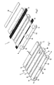
- the Fig. 4 shows the nail station 18 in a perspective view.
- the nail station 18 consists of a table-like pad 25, which is provided with a fixed bar 26 to form a first stop for the one end of the pallet 1.
- a fixed bar 26 Offset by 90 ° to this strip 26, three fixed angles 27a-27c are arranged, which serve as stops for the one longitudinal side of the pallet 1. These three angles 27a-27c correspond in position to the three connection blocks 5a-5c (FIG. Fig. 1 ).
- a further bar 28 is arranged, which is displaceable in the longitudinal direction of the pallet 1.
- three plates 29a-29c are arranged, which are displaceable transversely to the longitudinal axis of the pallet 1.
- Both the displaceable strip 28 and the displaceable plates 29a-29c serve to position and fix the respective pallet 1 by pressing it against the fixed stops 26, 27a-27c by displacing the strip 28 and the plates 29a-29c.
- hydraulic cylinders 30a, 30b, 31-31c are provided to actuate the bar 28 and plates 29a-29c. The actuation of these hydraulic cylinders 30a, 30b, 31-31c is preferably also via the control unit 21.
Landscapes
- Engineering & Computer Science (AREA)
- Life Sciences & Earth Sciences (AREA)
- Mechanical Engineering (AREA)
- Manufacturing & Machinery (AREA)
- Wood Science & Technology (AREA)
- Forests & Forestry (AREA)
- Pallets (AREA)
- Feeding Of Workpieces (AREA)
- Jigs For Machine Tools (AREA)
- Automatic Assembly (AREA)
Priority Applications (2)
| Application Number | Priority Date | Filing Date | Title |
|---|---|---|---|
| PL06405472T PL1785220T3 (pl) | 2005-11-14 | 2006-11-07 | Sposób i urządzenie do naprawy uszkodzonych palet |
| SI200630477T SI1785220T1 (sl) | 2005-11-14 | 2006-11-07 | Postopek in naprava za popravljanje poškodovanih palet |
Applications Claiming Priority (1)
| Application Number | Priority Date | Filing Date | Title |
|---|---|---|---|
| CH18182005 | 2005-11-14 |
Publications (2)
| Publication Number | Publication Date |
|---|---|
| EP1785220A1 EP1785220A1 (de) | 2007-05-16 |
| EP1785220B1 true EP1785220B1 (de) | 2009-08-26 |
Family
ID=37596288
Family Applications (2)
| Application Number | Title | Priority Date | Filing Date |
|---|---|---|---|
| EP06405472A Active EP1785220B1 (de) | 2005-11-14 | 2006-11-07 | Verfahren und Vorrichtung zur Reparatur beschädigter Paletten |
| EP06405475A Active EP1785221B1 (de) | 2005-11-14 | 2006-11-10 | Vorrichtung zum Ausrichten und/oder Fixieren von zu reparierenden Paletten und/oder Palettenteilen |
Family Applications After (1)
| Application Number | Title | Priority Date | Filing Date |
|---|---|---|---|
| EP06405475A Active EP1785221B1 (de) | 2005-11-14 | 2006-11-10 | Vorrichtung zum Ausrichten und/oder Fixieren von zu reparierenden Paletten und/oder Palettenteilen |
Country Status (17)
| Country | Link |
|---|---|
| US (2) | US7954240B2 (pl) |
| EP (2) | EP1785220B1 (pl) |
| JP (2) | JP5129474B2 (pl) |
| KR (2) | KR101275383B1 (pl) |
| CN (2) | CN1974153B (pl) |
| AT (2) | ATE440694T1 (pl) |
| CA (2) | CA2567924C (pl) |
| DE (2) | DE502006004647D1 (pl) |
| ES (2) | ES2331152T3 (pl) |
| HR (2) | HRP20090574T1 (pl) |
| MX (2) | MXPA06013184A (pl) |
| NO (2) | NO338339B1 (pl) |
| PL (2) | PL1785220T3 (pl) |
| RU (2) | RU2359820C2 (pl) |
| SI (2) | SI1785220T1 (pl) |
| TW (2) | TWI371333B (pl) |
| UA (2) | UA89782C2 (pl) |
Cited By (1)
| Publication number | Priority date | Publication date | Assignee | Title |
|---|---|---|---|---|
| CN102717416A (zh) * | 2012-06-06 | 2012-10-10 | 缙云县欣宇金属制品有限公司 | 一种木托盘底座的生产流水线 |
Families Citing this family (57)
| Publication number | Priority date | Publication date | Assignee | Title |
|---|---|---|---|---|
| US7765668B2 (en) * | 2002-12-10 | 2010-08-03 | Chep Technology Pty Limited | Automated pallet inspection and repair |
| DE602004032378D1 (de) | 2003-12-19 | 2011-06-01 | Chep Technology Pty Ltd | Vorrichtung und verfahren zur automatisierten paletteninspektion und -reparatur |
| ES2264640B1 (es) * | 2005-06-17 | 2007-12-01 | Ferraplana, S.L. | Equipo automatico para la fabricacion de armaduras metalicas. |
| TWI371333B (en) * | 2005-11-14 | 2012-09-01 | Holliger Paletten Logistik Ag | Method and apparatus for repairing damaged pallets |
| CN101470465A (zh) * | 2007-12-27 | 2009-07-01 | 鸿富锦精密工业(深圳)有限公司 | 铰链定位治具 |
| US8266790B2 (en) | 2008-01-25 | 2012-09-18 | Chep Technology Pty. Limited | Board removal apparatus for a pallet |
| AU2008200441B8 (en) * | 2008-01-29 | 2011-04-21 | Chep Technology Pty Limited | Lead board adjustment apparatus for a pallet and associated methods |
| DE102008019589A1 (de) * | 2008-04-18 | 2009-10-22 | Gressel Ag | Mehrfachspanner |
| DE102008048383A1 (de) * | 2008-09-22 | 2010-03-25 | Baumer Inspection Gmbh | Automatisches Flicken von Holzpaneelen mit ästhetischer Rekonstruktion |
| US7896211B2 (en) * | 2009-01-13 | 2011-03-01 | Wen-Yi Tu | Nailing mechanism for a packing plates |
| NL2003646C2 (nl) * | 2009-10-15 | 2011-04-18 | Douna Engineering B V | Pallet-reparatie inrichting en werkwijze voor het repareren van een pallet. |
| SE534491C2 (sv) | 2010-11-19 | 2011-09-06 | Yaskawa Nordic Ab | Anordning för demontering av valda delar av sammanfogade lastpallar |
| KR101327288B1 (ko) | 2011-08-31 | 2013-11-11 | 주식회사 경주수출포장 | 목재 파렛트의 조립장치 |
| CN102310306A (zh) * | 2011-09-27 | 2012-01-11 | 江苏银河电子股份有限公司 | 快速修复用于冲压密集孔凹模的方法 |
| SE536443C2 (sv) * | 2012-03-16 | 2013-11-05 | Anordning och metod för reparation av en lastpall | |
| US8978241B2 (en) | 2012-07-31 | 2015-03-17 | CLM Pallet Recycling, Inc. | Pallet refurbishing apparatus and method |
| FR2994701B1 (fr) * | 2012-08-23 | 2014-09-26 | Bernard Eugene Marie Choquet | Mecanisme de reglage d'intervalles et/ou d'angle pour realiser une structure d'escalier ou d'etagement |
| US20140076954A1 (en) * | 2012-09-18 | 2014-03-20 | Stanley Fastening Systems, L.P. | Pallet nail clinching apparatus and methods |
| DE202013006761U1 (de) * | 2013-07-26 | 2013-08-29 | Gerd Rebmann | Oberflächenabtaster zur Erkennung von überstehenden Stahlnägeln in Einweg- oder Mehrwegpaletten. |
| DE102013218391A1 (de) * | 2013-09-13 | 2015-03-19 | Krones Ag | Vorrichtung und Verfahren zum Bewegen von Transportelementen in einer Behälterbehandlungsanlage |
| DE102015000196A1 (de) * | 2015-01-15 | 2016-07-21 | Böllhoff Verbindungstechnik GmbH | Schallreduktionsvorrichtung sowie ein Fügeverfahren und ein Bauteilbearbeitungsverfahren mit Schalldämmung |
| US9994299B2 (en) * | 2015-04-03 | 2018-06-12 | The Boeing Company | Tool and method of installing a bulkhead within a structure |
| CN104972541A (zh) * | 2015-05-06 | 2015-10-14 | 太仓顺风木业制品有限公司 | 一种模具及其使用方法 |
| CN106542281B (zh) * | 2015-09-21 | 2018-12-28 | 苏州科维新型包装有限公司 | 板条上料装置 |
| US9809351B1 (en) | 2017-01-18 | 2017-11-07 | Victor Oliver | Method and apparatus for constructing pallets |
| US10486328B2 (en) * | 2017-01-31 | 2019-11-26 | Palletec, Llc | Methods and systems for fastening bed foundations |
| CN108044538A (zh) * | 2017-02-18 | 2018-05-18 | 薛峰 | 一种文物古玩修复用夹持装置 |
| CN107486693B (zh) * | 2017-06-30 | 2019-06-21 | 东莞华贝电子科技有限公司 | 压机系统及其控制方法 |
| US10252867B2 (en) * | 2017-07-21 | 2019-04-09 | Chep Technology Pty Limited | Pallet positioning station and associated methods |
| CN107695668A (zh) * | 2017-10-31 | 2018-02-16 | 惠州市昇沪汽车紧固件科技有限公司 | 一种用于全自动穿垫机的螺丝固定板导正装置 |
| RU184234U1 (ru) * | 2017-11-17 | 2018-10-18 | Евгений Юрьевич Чирков | Механизм фиксации материала в заданном размере |
| JP7044326B2 (ja) * | 2018-04-11 | 2022-03-30 | 国立大学法人千葉大学 | 多軸ロボットの固定装置および加工システム |
| CN108858636B (zh) * | 2018-07-06 | 2020-12-11 | 平湖市飞天人图文设计有限公司 | 一种桌凳组装机器人 |
| CN108656295A (zh) * | 2018-07-13 | 2018-10-16 | 安徽派日特智能装备有限公司 | 一种木托盘打钉用工装模具 |
| CN108908556A (zh) * | 2018-07-13 | 2018-11-30 | 安徽派日特智能装备有限公司 | 一种木托盘打钉用底板模具 |
| CN108908555B (zh) * | 2018-07-13 | 2021-06-01 | 安徽派日特智能装备有限公司 | 一种木托盘打钉的面板模具 |
| CN109318315B (zh) * | 2018-09-08 | 2021-04-13 | 上海辉效工业自动化有限公司 | 木托盘半自动化拼装设备 |
| US11897141B2 (en) | 2018-11-19 | 2024-02-13 | Palletec, Llc | Automated fastening system |
| CN109333687A (zh) * | 2018-11-23 | 2019-02-15 | 海麟文博(厦门)文物预防性保护技术有限公司 | 一种木质文物复制方法 |
| IT201800011024A1 (it) * | 2018-12-12 | 2020-06-12 | Cosberg Spa | Macchina di presa per articoli |
| CN110032055A (zh) * | 2019-03-11 | 2019-07-19 | 博众精工科技股份有限公司 | 一种屏幕拆卸设备 |
| CN110523857A (zh) * | 2019-08-15 | 2019-12-03 | 佛山市顺德区亿盛达精密机械制造有限公司 | 一种应用在电机生产中的在线压合流水线 |
| CN110561309B (zh) * | 2019-10-12 | 2021-03-16 | 燕山大学 | 起落架试验机安装支座装配工艺与工装 |
| CN111360967B (zh) * | 2020-03-24 | 2022-01-25 | 上海中息信息科技有限公司 | 一种家居装饰木栅栏生产装置 |
| CN111890297A (zh) * | 2020-08-13 | 2020-11-06 | 北京北海建材集团有限公司 | 一种钢墙架组装模台 |
| CN112192151B (zh) * | 2020-09-29 | 2021-11-16 | 宁波横河精密工业股份有限公司 | 一种高精度密封阀门的生产工装及其工艺 |
| US11845584B2 (en) * | 2021-03-16 | 2023-12-19 | Alliance Automation, Llc | Pallet reassembly system |
| CN112849641B (zh) * | 2021-04-08 | 2022-05-03 | 锦州阳光能源有限公司 | 一种实现无纸箱包装的打包工艺 |
| CN113843723A (zh) * | 2021-08-17 | 2021-12-28 | 中车唐山机车车辆有限公司 | 顶板骨架定位工装 |
| CN113858370B (zh) * | 2021-10-13 | 2022-07-29 | 江南大学 | 一种木结构组合墙体的自动装配系统 |
| US12444035B2 (en) * | 2021-10-13 | 2025-10-14 | Chep Technology Pty Limited | Pallet inspection system and associated methods |
| CN114800734B (zh) * | 2022-04-28 | 2023-03-31 | 重庆佳利乐包装有限公司 | 一种木材免钉固定装置 |
| EP4491361B1 (en) * | 2023-01-17 | 2025-12-03 | Mecanica Cape, S.L. | Automatic pallet assembly system and method |
| CN116141451B (zh) * | 2023-04-03 | 2024-01-12 | 芜湖奔腾包装股份有限公司 | 一种木托盘生产用流水线式组装设备 |
| US20250018595A1 (en) * | 2023-07-11 | 2025-01-16 | Merrick Machine Co. | Automated assembler |
| WO2025024721A1 (en) * | 2023-07-25 | 2025-01-30 | Urban Machine, Inc. | System and method for removing metal fasteners embedded in wood products |
| CN120552165A (zh) * | 2025-07-18 | 2025-08-29 | 重庆倍耐尔科技有限公司 | 旋转打钉机器人及其工作方法 |
Family Cites Families (49)
| Publication number | Priority date | Publication date | Assignee | Title |
|---|---|---|---|---|
| US3591067A (en) * | 1969-05-28 | 1971-07-06 | Fmc Corp | Assembly jig for the nailing of wood frame members |
| US3880416A (en) * | 1973-11-05 | 1975-04-29 | Don A Horwitz | Fixture assembly for the repair of universal joints |
| US3941291A (en) * | 1974-08-09 | 1976-03-02 | Hayworth Leil W | Pallet jig and table |
| US3968560A (en) * | 1974-12-16 | 1976-07-13 | Fmc Corporation | Pallet assembling system |
| US4170345A (en) * | 1977-12-13 | 1979-10-09 | Townsend Ralph G | Holding clamp assembly |
| US4235005A (en) * | 1979-02-12 | 1980-11-25 | Palletron Incorporated | Apparatus for assembling pallets |
| US4435892A (en) * | 1979-11-05 | 1984-03-13 | Williams Panel Board Company | Method of disassembling wooden pallets |
| FR2471843A1 (fr) * | 1979-12-19 | 1981-06-26 | Perurena Palettes | Table universelle de clouage pour l'assemblage et le clouage de palettes de manutention |
| GB2136727B (en) * | 1983-02-15 | 1987-10-14 | Keith Shafto | Clamping and holding tool for woodwork |
| EP0154772B1 (de) * | 1984-01-26 | 1988-08-03 | BBC Brown Boveri AG | Bipolarplatte für einen aus mehreren elektrochemischen Zellen mit Feststoffelektrolyt aufgebauten stapelartigen Apparat und Verfahren zu deren Herstellung |
| SU1258693A1 (ru) * | 1985-02-15 | 1986-09-23 | Новороссийский Морской Торговый Порт | Лини изготовлени и ремонта дерев нных поддонов |
| SU1323388A1 (ru) * | 1985-10-29 | 1987-07-15 | Предприятие П/Я Г-4780 | Устройство дл изготовлени дерев нных поддонов |
| SU1380948A1 (ru) * | 1985-11-26 | 1988-03-15 | Орловский Филиал Проектно-Конструкторского Технологического Института Машиностроения | Устройство дл сборки дерев нных щитов |
| US4743154A (en) * | 1986-06-09 | 1988-05-10 | American Pallet Systems, Inc. | Pallet inspection and repair system |
| US5201110A (en) * | 1986-08-22 | 1993-04-13 | Bane Marvin L | Pallet dismantler |
| US4824004A (en) * | 1987-11-13 | 1989-04-25 | Hanson Garry L | Apparatus and method for forming a pallet |
| US5174004A (en) * | 1988-01-05 | 1992-12-29 | King & Sons Pty. Ltd. | Radiator clamping jig |
| JPH0292601A (ja) * | 1988-09-10 | 1990-04-03 | Accurate Tool & Mfg Inc | パレット製造装置 |
| JPH04176955A (ja) * | 1990-11-07 | 1992-06-24 | Dantani Plywood Co Ltd | 木質系床材 |
| US5060920A (en) * | 1990-12-20 | 1991-10-29 | Eddy Engibarov | Quick change jaw assembly for high precision machining |
| JPH04369502A (ja) * | 1991-06-19 | 1992-12-22 | Kanematsu Nnk Corp | パレット等の組板の形成方法及び装置 |
| US5211094A (en) * | 1991-11-15 | 1993-05-18 | Johnson John L | Cutter head for pallet dismantling machine |
| US5307554A (en) * | 1992-12-02 | 1994-05-03 | John L. Johnson | Pallet dismantling machine and cutter head assembly therefor |
| DE4308580A1 (de) * | 1993-03-18 | 1994-09-22 | Ketterer Maschinenbau Gmbh | Verfahren und Vorrichtungen zur Reparatur beschädigter Paletten |
| US5375315A (en) * | 1994-03-11 | 1994-12-27 | Litco International, Inc. | Pallet nail press and method of use |
| JPH0834439A (ja) * | 1994-07-26 | 1996-02-06 | Shiga Genboku:Kk | パレットとそのパレットにおける板枠の枠組方法 |
| DE4435574C1 (de) * | 1994-10-05 | 1996-06-20 | Dirk Heuser | Vorrichtung zur teilweisen oder vollständigen Demontage von defekten Holzpaletten |
| US5555617A (en) * | 1994-10-07 | 1996-09-17 | Pope; Harold W. | Pallet manufacturing apparatus |
| JPH08118171A (ja) * | 1994-10-20 | 1996-05-14 | Toppan Printing Co Ltd | 水平移動テーブル |
| US5947460A (en) * | 1995-11-02 | 1999-09-07 | Tee-Lok Corporation | Truss table with integrated positioning stops |
| US5848459A (en) * | 1996-05-22 | 1998-12-15 | Juston Minick | Pallet end board remover |
| ES2117575B1 (es) * | 1996-08-05 | 1999-04-01 | Chep Pooling Systems B V | Procedimiento para el reconocimiento y la clasificacion automaticos de defectos en paletas o elementos similares, y sistema correspondiente . |
| BE1011302A4 (fr) * | 1997-07-24 | 1999-07-06 | Petruzzi Francesco | Machine automatique de reparation de defauts reperes sur des palettes de manutention. |
| DE19822229A1 (de) * | 1998-03-17 | 1999-09-23 | Dirk Heuser | Verfahren und Vorrichtung zum Reparieren beschädigter Paletten aus Holz |
| US6058586A (en) * | 1998-05-18 | 2000-05-09 | Pallet Recycling, Inc. | Method and apparatus for repairing pallets |
| BE1013052A3 (fr) * | 1999-06-16 | 2001-08-07 | Petruzzi Francesco | Machine automatique perfectionnee pour la reparation generale des palettes de manutention defectueuses. |
| DE10015636A1 (de) * | 2000-03-29 | 2002-06-06 | Dirk Heuser | Vorrichtung und Verfahren zur Justierung und Arretierung von Paletten mitsamt anzubringender Holzteile |
| DE10025373A1 (de) * | 2000-05-23 | 2001-11-29 | Palettenwerk E & A Falkenhahn | Vorrichtung zur Herstellung von Paletten |
| JP2002282975A (ja) * | 2001-03-29 | 2002-10-02 | Aida Eng Ltd | 位置決め装置およびこれを具備するプレス機械 |
| US6394438B1 (en) * | 2001-05-11 | 2002-05-28 | Richard D. Glaser | Multilevel clamp device |
| US6687970B2 (en) * | 2002-04-30 | 2004-02-10 | Ronald L. Waechter | Method and device for removing pallet runners |
| US6763567B2 (en) * | 2002-05-14 | 2004-07-20 | Fastening Technologies, Llc | Pallet assembly device and method of assembling pallets |
| JP2004037327A (ja) * | 2002-07-05 | 2004-02-05 | Daifuku Co Ltd | パレットの破損検出装置 |
| US7765668B2 (en) * | 2002-12-10 | 2010-08-03 | Chep Technology Pty Limited | Automated pallet inspection and repair |
| US6829822B1 (en) * | 2003-06-27 | 2004-12-14 | Juston E. Minick | Pallet board removal assembly |
| US7117586B2 (en) * | 2003-07-09 | 2006-10-10 | Industrial Resources Of Michigan Inc. | Pallet dismantler |
| DE602004032378D1 (de) * | 2003-12-19 | 2011-06-01 | Chep Technology Pty Ltd | Vorrichtung und verfahren zur automatisierten paletteninspektion und -reparatur |
| EP1547724B1 (en) * | 2003-12-22 | 2008-02-20 | Juan José Martin Eizaguirre | Machine for shaping and re-nailing wooden pallets |
| TWI371333B (en) * | 2005-11-14 | 2012-09-01 | Holliger Paletten Logistik Ag | Method and apparatus for repairing damaged pallets |
-
2006
- 2006-11-06 TW TW095140964A patent/TWI371333B/zh not_active IP Right Cessation
- 2006-11-07 PL PL06405472T patent/PL1785220T3/pl unknown
- 2006-11-07 ES ES06405472T patent/ES2331152T3/es active Active
- 2006-11-07 EP EP06405472A patent/EP1785220B1/de active Active
- 2006-11-07 AT AT06405472T patent/ATE440694T1/de active
- 2006-11-07 SI SI200630477T patent/SI1785220T1/sl unknown
- 2006-11-07 DE DE502006004647T patent/DE502006004647D1/de active Active
- 2006-11-10 DE DE502006006226T patent/DE502006006226D1/de active Active
- 2006-11-10 SI SI200630665T patent/SI1785221T1/sl unknown
- 2006-11-10 EP EP06405475A patent/EP1785221B1/de active Active
- 2006-11-10 AT AT06405475T patent/ATE458580T1/de active
- 2006-11-10 PL PL06405475T patent/PL1785221T3/pl unknown
- 2006-11-10 ES ES06405475T patent/ES2341989T3/es active Active
- 2006-11-13 MX MXPA06013184A patent/MXPA06013184A/es active IP Right Grant
- 2006-11-13 CN CN2006101689619A patent/CN1974153B/zh not_active Expired - Fee Related
- 2006-11-13 US US11/559,076 patent/US7954240B2/en not_active Expired - Fee Related
- 2006-11-13 MX MXPA06013183A patent/MXPA06013183A/es active IP Right Grant
- 2006-11-13 KR KR1020060111372A patent/KR101275383B1/ko not_active Expired - Fee Related
- 2006-11-13 UA UAA200611965A patent/UA89782C2/ru unknown
- 2006-11-13 UA UAA200611963A patent/UA90675C2/ru unknown
- 2006-11-13 NO NO20065197A patent/NO338339B1/no not_active IP Right Cessation
- 2006-11-13 NO NO20065203A patent/NO339534B1/no not_active IP Right Cessation
- 2006-11-13 RU RU2006139972/11A patent/RU2359820C2/ru not_active IP Right Cessation
- 2006-11-13 JP JP2006306979A patent/JP5129474B2/ja not_active Expired - Fee Related
- 2006-11-13 US US11/559,168 patent/US7815177B2/en not_active Expired - Fee Related
- 2006-11-13 RU RU2006139979/11A patent/RU2368483C2/ru not_active IP Right Cessation
- 2006-11-13 JP JP2006306893A patent/JP5156220B2/ja not_active Expired - Fee Related
- 2006-11-14 TW TW095142043A patent/TWI388393B/zh not_active IP Right Cessation
- 2006-11-14 KR KR1020060112272A patent/KR101279708B1/ko not_active Expired - Fee Related
- 2006-11-14 CA CA2567924A patent/CA2567924C/en not_active Expired - Fee Related
- 2006-11-14 CN CN2006101723836A patent/CN1970257B/zh not_active Expired - Fee Related
- 2006-11-14 CA CA2567926A patent/CA2567926C/en not_active Expired - Fee Related
-
2009
- 2009-10-29 HR HR20090574T patent/HRP20090574T1/hr unknown
-
2010
- 2010-04-20 HR HR20100232T patent/HRP20100232T1/hr unknown
Cited By (2)
| Publication number | Priority date | Publication date | Assignee | Title |
|---|---|---|---|---|
| CN102717416A (zh) * | 2012-06-06 | 2012-10-10 | 缙云县欣宇金属制品有限公司 | 一种木托盘底座的生产流水线 |
| CN102717416B (zh) * | 2012-06-06 | 2015-01-21 | 缙云县欣宇金属制品有限公司 | 一种木托盘底座的生产流水线 |
Also Published As
Similar Documents
| Publication | Publication Date | Title |
|---|---|---|
| EP1785220A1 (de) | Verfahren und Vorrichtung zur Reparatur beschädigter Paletten | |
| EP2143524B1 (de) | Vorrichtung zum Fördern eines Werkstücks | |
| EP1990151B1 (de) | Bearbeitungsmachine | |
| DE60207301T2 (de) | Nietvorrichtung zum gleichzeitigen nieten von flachen oberflächen | |
| DE4101904A1 (de) | Verfahren und vorrichtung zur schnittholzbearbeitung | |
| EP3967466A1 (de) | Plattenaufteilanlage zum aufteilen von plattenförmigen werkstücken, sowie verfahren zu deren betrieb | |
| EP4247586B1 (de) | Entladestation für eine bearbeitungsmaschine sowie bearbeitungsmaschine zum schneidenden bearbeiten von rohr- oder stangenförmigen werkstücken | |
| DE10021802B4 (de) | Verfahren zur Hochleistungssortierung von Paletten | |
| EP0943394A2 (de) | Verfahren und Vorrichtung zum Reparieren beschädigter Paletten aus Holz | |
| DE4308580A1 (de) | Verfahren und Vorrichtungen zur Reparatur beschädigter Paletten | |
| EP4696475A2 (de) | Holzbearbeitungsvorrichtung, holzbearbeitungsanlage und verfahren | |
| DE2400235C2 (de) | An einer Senkrechträummaschine angeordnete Fördereinrichtung zum Hochfördern von Werkstücken vor mindestens eine Werkstückvorlage | |
| DE19823040A1 (de) | Verfahren und Vorrichtung zur Übergabe von Befestigungselementen an Stanzköpfe | |
| WO1991007072A1 (de) | Anordnung zum bohren von leiterplatten | |
| DE3904805C2 (pl) | ||
| DE19822229A1 (de) | Verfahren und Vorrichtung zum Reparieren beschädigter Paletten aus Holz | |
| AT402273B (de) | Bandsäge für das schneiden von stämmen | |
| DE4435574C1 (de) | Vorrichtung zur teilweisen oder vollständigen Demontage von defekten Holzpaletten | |
| EP2527112A2 (de) | Bearbeitungsvorrichtung | |
| DE19910028A1 (de) | Bearbeitungsautomat mit austauschbaren Arbeitsmodulen | |
| DE10111326A1 (de) | Sägeeinrichtun für Platten aus Holz, Kunststoff o. dgl. | |
| DE102009004682B4 (de) | Verfahren und Vorrichtung zum Vereinzeln von flachen Leisten zur Herstellung einer Mittellage einer Parkettdiele | |
| EP0183117A1 (de) | Positioniervorrichtung für Werkstücke auf einem Tragelement | |
| DE3337126A1 (de) | Vorrichtung zur abgabe und/oder aufnahme von platten, insbesondere leiterplatten, von bzw. in einem plattenstapel | |
| DE102005010795A1 (de) | Anordnung und Verfahren zum Sortieren von Holz-Halbwaren |
Legal Events
| Date | Code | Title | Description |
|---|---|---|---|
| PUAI | Public reference made under article 153(3) epc to a published international application that has entered the european phase |
Free format text: ORIGINAL CODE: 0009012 |
|
| AK | Designated contracting states |
Kind code of ref document: A1 Designated state(s): AT BE BG CH CY CZ DE DK EE ES FI FR GB GR HU IE IS IT LI LT LU LV MC NL PL PT RO SE SI SK TR |
|
| AX | Request for extension of the european patent |
Extension state: AL BA HR MK YU |
|
| 17P | Request for examination filed |
Effective date: 20070711 |
|
| AKX | Designation fees paid |
Designated state(s): AT BE BG CH CY CZ DE DK EE ES FI FR GB GR HU IE IS IT LI LT LU LV MC NL PL PT RO SE SI SK TR |
|
| AXX | Extension fees paid |
Extension state: BA Payment date: 20061129 Extension state: MK Payment date: 20061129 Extension state: AL Payment date: 20061129 Extension state: HR Payment date: 20061129 Extension state: YU Payment date: 20061129 |
|
| RAX | Requested extension states of the european patent have changed |
Extension state: HR Payment date: 20061129 Extension state: AL Payment date: 20061129 Extension state: RS Payment date: 20061129 Extension state: BA Payment date: 20061129 Extension state: MK Payment date: 20061129 |
|
| GRAP | Despatch of communication of intention to grant a patent |
Free format text: ORIGINAL CODE: EPIDOSNIGR1 |
|
| GRAS | Grant fee paid |
Free format text: ORIGINAL CODE: EPIDOSNIGR3 |
|
| GRAA | (expected) grant |
Free format text: ORIGINAL CODE: 0009210 |
|
| AK | Designated contracting states |
Kind code of ref document: B1 Designated state(s): AT BE BG CH CY CZ DE DK EE ES FI FR GB GR HU IE IS IT LI LT LU LV MC NL PL PT RO SE SI SK TR |
|
| AX | Request for extension of the european patent |
Extension state: AL BA HR MK RS |
|
| REG | Reference to a national code |
Ref country code: GB Ref legal event code: FG4D Free format text: NOT ENGLISH |
|
| REG | Reference to a national code |
Ref country code: CH Ref legal event code: NV Representative=s name: ROTTMANN, ZIMMERMANN + PARTNER AG Ref country code: CH Ref legal event code: EP |
|
| REG | Reference to a national code |
Ref country code: IE Ref legal event code: FG4D Free format text: LANGUAGE OF EP DOCUMENT: GERMAN |
|
| REF | Corresponds to: |
Ref document number: 502006004647 Country of ref document: DE Date of ref document: 20091008 Kind code of ref document: P |
|
| REG | Reference to a national code |
Ref country code: HR Ref legal event code: TUEP Ref document number: P20090574 Country of ref document: HR |
|
| REG | Reference to a national code |
Ref country code: ES Ref legal event code: FG2A Ref document number: 2331152 Country of ref document: ES Kind code of ref document: T3 |
|
| LTIE | Lt: invalidation of european patent or patent extension |
Effective date: 20090826 |
|
| PG25 | Lapsed in a contracting state [announced via postgrant information from national office to epo] |
Ref country code: FI Free format text: LAPSE BECAUSE OF FAILURE TO SUBMIT A TRANSLATION OF THE DESCRIPTION OR TO PAY THE FEE WITHIN THE PRESCRIBED TIME-LIMIT Effective date: 20090826 Ref country code: LT Free format text: LAPSE BECAUSE OF FAILURE TO SUBMIT A TRANSLATION OF THE DESCRIPTION OR TO PAY THE FEE WITHIN THE PRESCRIBED TIME-LIMIT Effective date: 20090826 Ref country code: IS Free format text: LAPSE BECAUSE OF FAILURE TO SUBMIT A TRANSLATION OF THE DESCRIPTION OR TO PAY THE FEE WITHIN THE PRESCRIBED TIME-LIMIT Effective date: 20091226 Ref country code: SE Free format text: LAPSE BECAUSE OF FAILURE TO SUBMIT A TRANSLATION OF THE DESCRIPTION OR TO PAY THE FEE WITHIN THE PRESCRIBED TIME-LIMIT Effective date: 20090826 |
|
| REG | Reference to a national code |
Ref country code: PL Ref legal event code: T3 |
|
| REG | Reference to a national code |
Ref country code: HR Ref legal event code: T1PR Ref document number: P20090574 Country of ref document: HR |
|
| PG25 | Lapsed in a contracting state [announced via postgrant information from national office to epo] |
Ref country code: LV Free format text: LAPSE BECAUSE OF FAILURE TO SUBMIT A TRANSLATION OF THE DESCRIPTION OR TO PAY THE FEE WITHIN THE PRESCRIBED TIME-LIMIT Effective date: 20090826 |
|
| PG25 | Lapsed in a contracting state [announced via postgrant information from national office to epo] |
Ref country code: CY Free format text: LAPSE BECAUSE OF FAILURE TO SUBMIT A TRANSLATION OF THE DESCRIPTION OR TO PAY THE FEE WITHIN THE PRESCRIBED TIME-LIMIT Effective date: 20090826 Ref country code: BG Free format text: LAPSE BECAUSE OF FAILURE TO SUBMIT A TRANSLATION OF THE DESCRIPTION OR TO PAY THE FEE WITHIN THE PRESCRIBED TIME-LIMIT Effective date: 20091126 Ref country code: PT Free format text: LAPSE BECAUSE OF FAILURE TO SUBMIT A TRANSLATION OF THE DESCRIPTION OR TO PAY THE FEE WITHIN THE PRESCRIBED TIME-LIMIT Effective date: 20091228 |
|
| REG | Reference to a national code |
Ref country code: IE Ref legal event code: FD4D |
|
| REG | Reference to a national code |
Ref country code: SK Ref legal event code: T3 Ref document number: E 6568 Country of ref document: SK |
|
| PG25 | Lapsed in a contracting state [announced via postgrant information from national office to epo] |
Ref country code: DK Free format text: LAPSE BECAUSE OF FAILURE TO SUBMIT A TRANSLATION OF THE DESCRIPTION OR TO PAY THE FEE WITHIN THE PRESCRIBED TIME-LIMIT Effective date: 20090826 Ref country code: EE Free format text: LAPSE BECAUSE OF FAILURE TO SUBMIT A TRANSLATION OF THE DESCRIPTION OR TO PAY THE FEE WITHIN THE PRESCRIBED TIME-LIMIT Effective date: 20090826 Ref country code: RO Free format text: LAPSE BECAUSE OF FAILURE TO SUBMIT A TRANSLATION OF THE DESCRIPTION OR TO PAY THE FEE WITHIN THE PRESCRIBED TIME-LIMIT Effective date: 20090826 Ref country code: IE Free format text: LAPSE BECAUSE OF FAILURE TO SUBMIT A TRANSLATION OF THE DESCRIPTION OR TO PAY THE FEE WITHIN THE PRESCRIBED TIME-LIMIT Effective date: 20090826 |
|
| PG25 | Lapsed in a contracting state [announced via postgrant information from national office to epo] |
Ref country code: MC Free format text: LAPSE BECAUSE OF NON-PAYMENT OF DUE FEES Effective date: 20091130 |
|
| PLBE | No opposition filed within time limit |
Free format text: ORIGINAL CODE: 0009261 |
|
| STAA | Information on the status of an ep patent application or granted ep patent |
Free format text: STATUS: NO OPPOSITION FILED WITHIN TIME LIMIT |
|
| 26N | No opposition filed |
Effective date: 20100527 |
|
| PG25 | Lapsed in a contracting state [announced via postgrant information from national office to epo] |
Ref country code: GR Free format text: LAPSE BECAUSE OF FAILURE TO SUBMIT A TRANSLATION OF THE DESCRIPTION OR TO PAY THE FEE WITHIN THE PRESCRIBED TIME-LIMIT Effective date: 20091127 |
|
| PG25 | Lapsed in a contracting state [announced via postgrant information from national office to epo] |
Ref country code: LU Free format text: LAPSE BECAUSE OF NON-PAYMENT OF DUE FEES Effective date: 20091107 |
|
| PG25 | Lapsed in a contracting state [announced via postgrant information from national office to epo] |
Ref country code: HU Free format text: LAPSE BECAUSE OF FAILURE TO SUBMIT A TRANSLATION OF THE DESCRIPTION OR TO PAY THE FEE WITHIN THE PRESCRIBED TIME-LIMIT Effective date: 20100227 |
|
| PG25 | Lapsed in a contracting state [announced via postgrant information from national office to epo] |
Ref country code: TR Free format text: LAPSE BECAUSE OF FAILURE TO SUBMIT A TRANSLATION OF THE DESCRIPTION OR TO PAY THE FEE WITHIN THE PRESCRIBED TIME-LIMIT Effective date: 20090826 |
|
| REG | Reference to a national code |
Ref country code: CH Ref legal event code: PFA Owner name: HOLLIGER PALETTEN LOGISTIK AG Free format text: HOLLIGER PALETTEN LOGISTIK AG#RIEDWEG 5#5706 BONISWIL (CH) -TRANSFER TO- HOLLIGER PALETTEN LOGISTIK AG#RIEDWEG 5#5706 BONISWIL (CH) |
|
| REG | Reference to a national code |
Ref country code: FR Ref legal event code: PLFP Year of fee payment: 10 |
|
| REG | Reference to a national code |
Ref country code: CH Ref legal event code: PCAR Free format text: NEW ADDRESS: GARTENSTRASSE 28 A, 5400 BADEN (CH) |
|
| REG | Reference to a national code |
Ref country code: FR Ref legal event code: PLFP Year of fee payment: 11 |
|
| REG | Reference to a national code |
Ref country code: FR Ref legal event code: PLFP Year of fee payment: 12 |
|
| REG | Reference to a national code |
Ref country code: HR Ref legal event code: ODRP Ref document number: P20090574 Country of ref document: HR Payment date: 20181030 Year of fee payment: 13 |
|
| PGFP | Annual fee paid to national office [announced via postgrant information from national office to epo] |
Ref country code: NL Payment date: 20181120 Year of fee payment: 13 |
|
| PGFP | Annual fee paid to national office [announced via postgrant information from national office to epo] |
Ref country code: AT Payment date: 20181121 Year of fee payment: 13 Ref country code: CZ Payment date: 20181023 Year of fee payment: 13 Ref country code: PL Payment date: 20181022 Year of fee payment: 13 Ref country code: SK Payment date: 20181023 Year of fee payment: 13 Ref country code: DE Payment date: 20181120 Year of fee payment: 13 |
|
| PGFP | Annual fee paid to national office [announced via postgrant information from national office to epo] |
Ref country code: FR Payment date: 20181123 Year of fee payment: 13 Ref country code: IT Payment date: 20181126 Year of fee payment: 13 Ref country code: BE Payment date: 20181120 Year of fee payment: 13 Ref country code: ES Payment date: 20181218 Year of fee payment: 13 Ref country code: GB Payment date: 20181120 Year of fee payment: 13 Ref country code: CH Payment date: 20181120 Year of fee payment: 13 Ref country code: SI Payment date: 20181019 Year of fee payment: 13 |
|
| REG | Reference to a national code |
Ref country code: HR Ref legal event code: PBON Ref document number: P20090574 Country of ref document: HR Effective date: 20191107 |
|
| REG | Reference to a national code |
Ref country code: DE Ref legal event code: R119 Ref document number: 502006004647 Country of ref document: DE |
|
| REG | Reference to a national code |
Ref country code: CH Ref legal event code: PL |
|
| REG | Reference to a national code |
Ref country code: NL Ref legal event code: MM Effective date: 20191201 |
|
| PG25 | Lapsed in a contracting state [announced via postgrant information from national office to epo] |
Ref country code: CH Free format text: LAPSE BECAUSE OF NON-PAYMENT OF DUE FEES Effective date: 20191130 Ref country code: LI Free format text: LAPSE BECAUSE OF NON-PAYMENT OF DUE FEES Effective date: 20191130 Ref country code: CZ Free format text: LAPSE BECAUSE OF NON-PAYMENT OF DUE FEES Effective date: 20191107 |
|
| REG | Reference to a national code |
Ref country code: SK Ref legal event code: MM4A Ref document number: E 6568 Country of ref document: SK Effective date: 20191107 |
|
| REG | Reference to a national code |
Ref country code: AT Ref legal event code: MM01 Ref document number: 440694 Country of ref document: AT Kind code of ref document: T Effective date: 20191107 |
|
| REG | Reference to a national code |
Ref country code: BE Ref legal event code: MM Effective date: 20191130 |
|
| PG25 | Lapsed in a contracting state [announced via postgrant information from national office to epo] |
Ref country code: SK Free format text: LAPSE BECAUSE OF NON-PAYMENT OF DUE FEES Effective date: 20191107 |
|
| GBPC | Gb: european patent ceased through non-payment of renewal fee |
Effective date: 20191107 |
|
| PG25 | Lapsed in a contracting state [announced via postgrant information from national office to epo] |
Ref country code: NL Free format text: LAPSE BECAUSE OF NON-PAYMENT OF DUE FEES Effective date: 20191201 |
|
| PG25 | Lapsed in a contracting state [announced via postgrant information from national office to epo] |
Ref country code: FR Free format text: LAPSE BECAUSE OF NON-PAYMENT OF DUE FEES Effective date: 20191130 Ref country code: IT Free format text: LAPSE BECAUSE OF NON-PAYMENT OF DUE FEES Effective date: 20191107 Ref country code: GB Free format text: LAPSE BECAUSE OF NON-PAYMENT OF DUE FEES Effective date: 20191107 Ref country code: DE Free format text: LAPSE BECAUSE OF NON-PAYMENT OF DUE FEES Effective date: 20200603 |
|
| PG25 | Lapsed in a contracting state [announced via postgrant information from national office to epo] |
Ref country code: AT Free format text: LAPSE BECAUSE OF NON-PAYMENT OF DUE FEES Effective date: 20191107 Ref country code: SI Free format text: LAPSE BECAUSE OF NON-PAYMENT OF DUE FEES Effective date: 20191108 Ref country code: BE Free format text: LAPSE BECAUSE OF NON-PAYMENT OF DUE FEES Effective date: 20191130 |
|
| REG | Reference to a national code |
Ref country code: SI Ref legal event code: KO00 Effective date: 20201030 |
|
| REG | Reference to a national code |
Ref country code: ES Ref legal event code: FD2A Effective date: 20210414 |
|
| PG25 | Lapsed in a contracting state [announced via postgrant information from national office to epo] |
Ref country code: PL Free format text: LAPSE BECAUSE OF NON-PAYMENT OF DUE FEES Effective date: 20191107 Ref country code: ES Free format text: LAPSE BECAUSE OF NON-PAYMENT OF DUE FEES Effective date: 20191108 |