EP1806568A1 - Élément piézoélectrique et procédé de fabrication dudit élément - Google Patents
Élément piézoélectrique et procédé de fabrication dudit élément Download PDFInfo
- Publication number
- EP1806568A1 EP1806568A1 EP05768444A EP05768444A EP1806568A1 EP 1806568 A1 EP1806568 A1 EP 1806568A1 EP 05768444 A EP05768444 A EP 05768444A EP 05768444 A EP05768444 A EP 05768444A EP 1806568 A1 EP1806568 A1 EP 1806568A1
- Authority
- EP
- European Patent Office
- Prior art keywords
- piezoelectric
- pressure sensitive
- piezoelectric element
- sensitive substance
- water
- Prior art date
- Legal status (The legal status is an assumption and is not a legal conclusion. Google has not performed a legal analysis and makes no representation as to the accuracy of the status listed.)
- Withdrawn
Links
Images



Classifications
-
- H—ELECTRICITY
- H10—SEMICONDUCTOR DEVICES; ELECTRIC SOLID-STATE DEVICES NOT OTHERWISE PROVIDED FOR
- H10N—ELECTRIC SOLID-STATE DEVICES NOT OTHERWISE PROVIDED FOR
- H10N30/00—Piezoelectric or electrostrictive devices
-
- G—PHYSICS
- G01—MEASURING; TESTING
- G01L—MEASURING FORCE, STRESS, TORQUE, WORK, MECHANICAL POWER, MECHANICAL EFFICIENCY, OR FLUID PRESSURE
- G01L9/00—Measuring steady of quasi-steady pressure of fluid or fluent solid material by electric or magnetic pressure-sensitive elements; Transmitting or indicating the displacement of mechanical pressure-sensitive elements, used to measure the steady or quasi-steady pressure of a fluid or fluent solid material, by electric or magnetic means
- G01L9/0041—Transmitting or indicating the displacement of flexible diaphragms
- G01L9/008—Transmitting or indicating the displacement of flexible diaphragms using piezoelectric devices
-
- G—PHYSICS
- G01—MEASURING; TESTING
- G01L—MEASURING FORCE, STRESS, TORQUE, WORK, MECHANICAL POWER, MECHANICAL EFFICIENCY, OR FLUID PRESSURE
- G01L1/00—Measuring force or stress, in general
- G01L1/16—Measuring force or stress, in general using properties of piezoelectric devices
-
- H—ELECTRICITY
- H10—SEMICONDUCTOR DEVICES; ELECTRIC SOLID-STATE DEVICES NOT OTHERWISE PROVIDED FOR
- H10N—ELECTRIC SOLID-STATE DEVICES NOT OTHERWISE PROVIDED FOR
- H10N30/00—Piezoelectric or electrostrictive devices
- H10N30/01—Manufacture or treatment
- H10N30/09—Forming piezoelectric or electrostrictive materials
- H10N30/092—Forming composite materials
-
- H—ELECTRICITY
- H10—SEMICONDUCTOR DEVICES; ELECTRIC SOLID-STATE DEVICES NOT OTHERWISE PROVIDED FOR
- H10N—ELECTRIC SOLID-STATE DEVICES NOT OTHERWISE PROVIDED FOR
- H10N30/00—Piezoelectric or electrostrictive devices
- H10N30/80—Constructional details
- H10N30/85—Piezoelectric or electrostrictive active materials
- H10N30/852—Composite materials, e.g. having 1-3 or 2-2 type connectivity
-
- H—ELECTRICITY
- H10—SEMICONDUCTOR DEVICES; ELECTRIC SOLID-STATE DEVICES NOT OTHERWISE PROVIDED FOR
- H10N—ELECTRIC SOLID-STATE DEVICES NOT OTHERWISE PROVIDED FOR
- H10N30/00—Piezoelectric or electrostrictive devices
- H10N30/80—Constructional details
- H10N30/88—Mounts; Supports; Enclosures; Casings
- H10N30/883—Additional insulation means preventing electrical, physical or chemical damage, e.g. protective coatings
Definitions
- the present invention relates to a piezoelectric element using a piezoelectric composition pressure sensitive substance made by mixing piezoelectric ceramic powders in organic polymers.
- the present invention relates to a piezoelectric element used as a flexible pressure sensitive sensor, and a method of manufacturing the same.
- Japanese Patent Unexamined Publication No. 11-201835 discloses a piezoelectric composition pressure sensitive substance having an excellent piezoelectric property and flexibility.
- This piezoelectric composition pressure sensitive substance is made by mixing and kneading materials including a titanium coupling agent, a piezoelectric ceramic powder, and at least one of chlorinated polyethylene and chlorosulfonated polyethylene.
- the kneaded materials have flexibility because they contain a thermoplastic elastomer such as chlorinated polyethylene, so that they are processed into a sheet or cable form.
- the thus processed formed product is a piezoelectric composition pressure sensitive substance to which a pair of electrodes are connected so as to be used as a piezoelectric element.
- the piezoelectric composition pressure sensitive substance itself is softened and the relation between the pressure and the distortion of the piezoelectric element is changed. Therefore, a signal processing in accordance with the change in the softness of the piezoelectric element is required, and a complicated detection circuit is required because detection error may occur.
- the softening of the piezoelectric element lowers the tensile strength of the piezoelectric element, the durability is deteriorated.
- piezoelectric ceramic powders containing alkali metals of Group I and alkaline earth metals of Group II of the Periodic Table have a small specific resistance and are easily eluted in water, the electric resistance is remarkably lowered.
- a piezoelectric element of the present invention has a piezoelectric composition pressure sensitive substance, a first electrode, a second electrode and a covering layer.
- the piezoelectric composition pressure sensitive substance includes piezoelectric ceramic powders and flexible organic polymers.
- the first and second electrodes are connected to the piezoelectric composition pressure sensitive substance and insulated from each other.
- the covering layer is provided outside of the piezoelectric ceramic powder and suppresses absorption of water by the piezoelectric ceramic powder.
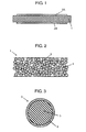
- Fig. 1 is a cross-sectional view showing a sheet-like piezoelectric element in accordance with a first exemplary embodiment of the present invention.
- pressure sensitive substance hereinafter, referred to as pressure sensitive substance 1
- electrode 2A as a first electrode
- electrode 2B as a second electrode
- Electrode 2A and electrode 2B are electrically insulated from each other.
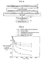
- Fig. 2 is a schematic view showing a cross-sectional structure of pressure sensitive substance 1.
- Pressure sensitive substance 1 includes water-repellent treated piezoelectric ceramic powders 3 and flexible organic polymers 4. Water-repellent treated piezoelectric ceramic powders 3 and organic polymers 4 are uniformly dispersed.
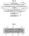
- Fig. 3 is a schematic view showing a cross section of one water-repellent treated piezoelectric ceramic powder 3.
- Water-repellent treated piezoelectric ceramic powder 3 has covering layer 6 provided by carrying out a water-repellent treatment on the surface of piezoelectric ceramic powder 5.
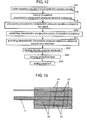
- piezoelectric ceramic powder 5 covering layer 6 provided by carrying out a water-repellent treatment is formed on piezoelectric ceramic powder 5 (S1).
- piezoelectric ceramic powder 5 is soaked in a solution containing a water-repellent material, which has been adjusted to a predetermined concentration by diluting with an appropriate solvent.
- water-repellent treated piezoelectric ceramic powders 3 and organic polymers 4 are kneaded (S2).
- a processor such as a kneader, a roll, or the like
- kneading is carried out so that water-repellent treated piezoelectric ceramic powders 3 are uniformly mixed and dispersed in organic polymers 4.
- a titanium coupling agent may be added.
- Electrodes 2A and 2B may be formed by fusion-bonding a conductive sheet formed by mixing and diffusing conductive powders into flexible organic polymers such as rubber and a thermoplastic elastomer. Alternatively, electrodes 2A and 2B may be formed by vapor-depositing a conductive material.
- a poling treatment is carried out by applying a direct voltage between electrodes 2A and 2B in the air or in a silicon oil bath (S5), and thus a sheet-like piezoelectric element is formed.
- the poling treatment (S5) is carried out after electrodes 2A and 2B are formed (S4), but it may be carried out by using two dummy electrodes after sheet-like pressure sensitive substance 1 is formed (S3).
- the piezoelectric property of the piezoelectric element is expressed by carrying out a poling treatment with respect to pressure sensitive substance 1 by applying a high direct voltage between electrodes 2A and 2B as mentioned above.
- pressure that changes over time is applied to a part or an entire surface of the sheet-like piezoelectric element expressing a piezoelectric property, oscillatory voltage according to acceleration generated therein is induced between electrodes 2A and 2B. Pressure can be detected by using this induced voltage.
- the piezoelectric element of this exemplary embodiment can be used as a pressure sensitive sensor and a vibration sensor. Furthermore, by providing the piezoelectric element of this exemplary embodiment in an automobile door, it can be used as a sensor for detecting something caught in the door, or by providing it in a care bed, it can be used as a sensor for detecting body motion. Such pressure sensitive sensors may be used outside as a pressure sensitive sensor or a vibration sensor. Furthermore, in a state in which such a sensor is mounted on an automobile, it is highly likely to be used in a high-temperature and high-humidity environment in the rain in summer. Furthermore, when such a sensor is incorporated in a care bed, it is highly likely to be used in a moist environment by incontinence or sweat, or a high-temperature and high-humidity environment in washing and cleaning to keep sanitation.
- covering layer 6 formed by carrying out a water-repellent treatment is provided on piezoelectric ceramic powder 5 forming pressure sensitive substance 1. Therefore, even when water vapor is condensed to generate water inside pressure sensitive substance 1, elution of components of piezoelectric ceramic powder 5 or impurities by infiltrated water is suppressed. That it to say, covering layer 6 suppress absorption of water by piezoelectric ceramic powder 5.
- the piezoelectric element of this exemplary embodiment is used as a pressure sensitive sensor, since covering layer 6 prevents absorption of water by pressure sensitive substance 1, pressure sensitive substance 1 can be suppressed from being softened. Thus, the initial piezoelectric property can be always maintained. As a result, since a signal processing according to the change in the piezoelectric property when the same pressure is applied, is not required, it is possible to design a detection circuit and a control circuit having a high reliability, for example, being capable of preventing error detection.
- pressure sensitive substance 1 forming a piezoelectric element can be suppressed from being softened, the tensile strength of pressure sensitive substance 1 can be prevented from being reduced and the initial strength can be maintained. Thus, excellent durability can be realized.
- piezoelectric ceramic powder 5 is compatible with water-repellent organic polymer 4 excellently.
- kneading property thereof is improved, and thus the productivity is improved, for example, the kneading processing time is shortened.
- the kneading time is the same as the conventional time, the amount of titanium coupling agents used for improving the kneading can be reduced, and thus the cost of materials can be reduced.
- water-repellent material for covering layer 6 can include a material containing an organic fatty acid salt, an organic fatty acid amide, fluororesin, silicone resin, acrylic resin and a silane compound as a main component.
- Examples of the organic fatty acid salt can include a compound of fatty acid such as caprylic acid, pelargonic acid, capric acid, undecylic acid, lauric acid, tridecylic acid, myristic acid, pentadecylic acid, palmitic acid, heptadecylic acid, stearic acid, nonadecanoic acid, arachidic acid, behenic acid, lignoceric acid, cerotic acid, heptacosanoic acid, montanoic acid, acrylic acid, crotonic acid, isocrotonic acid, undecylenic acid, oleic acid, elaidic acid, cetoleic acid, erucic acid, brassidic acid, sorbic acid, linoleic acid, and linolenic acid, and metallic element such as calcium, zinc, sodium, potassium, magnesium, copper and lead. At least one fatty acid salt thereof is used.
- fatty acid salt thereof is used.
- Examples of the organic fatty acid amide can include compounds in which a hydrogen group in fatty acids is substituted by an amino group.
- the fatty acids include caprylic acid, pelargonic acid, capric acid, undecylic acid, lauric acid, tridecylic acid, myristic acid, pentadecylic acid, palmitic acid, heptadecylic acid, stearic acid, nonadecanoic acid, arachidic acid, behenic acid, lignoceric acid, cerotic acid, heptacosanoic acid, montanoic acid, acrylic acid, crotonic acid, isocrotonic acid, undecylenic acid, oleic acid, elaidic acid, cetoleic acid, erucic acid, brassidic acid, sorbic acid, linoleic acid, and linolenic acid.
- fluororesin can include polytetrafluoroethylene (PTFE) and perfluoroalkylethylacrylate
- examples of the silicone resin can include dimethylpolysiloxane, diethylpolysiloxane and a silicone - acrylic block copolymer
- examples of the acrylic resin can include a polymer of methacrylic acid ester and acrylic acid ester.
- silane compound can include a alkylsilane compound and a fluorosilane compound having at least a siloxane bond on the surface of piezoelectric ceramic powder 5 and at least an alkyl group or a fluoroalkyl group.
- silane compounds the following compounds are effective. (1) SiX 4 (2) SiX 3 -O-SiX 3
- the compounds can include: (3) Si(OC 2 H 5 ) 4 (4) Si(OCH 3 ) 3 -O-Si(OCH 3 ) 3 (5) Si(OC 2 H 5 ) 3 -O-Si(OCH 3 ) 3 (6) Si(OC 2 H 5 ) 3 -O-Si(OC 2 H 5 ) 3 (7) Si(NCO) 4 (8) Si(NCO) 3 -O-Si(NCO) 3 (9) SiCl 4 (10) SiCl 3 -O-SiCl 3
- Examples of the silane compounds can include: (11) SiY p Cl 4-p (12) CH 3 (CH 2 ) s O(CH 2 ) t SiY q Cl 3-q (13) CH 3 (CH 2 ) u -Si(CH 3 ) 2 (CH 2 ) v -SiY q Cl 3-q (14) CF 3 COO(CH 2 ) w SiY q Cl 3-q wherein, p denotes an integer from 1 to 3; q denotes an integer from 0 to 2; r denotes an integer from 1 to 25; s denotes an integer from 0 to 12; t denotes an integer from 1 to 20; u denotes an integer from 0 to 12; v denotes an integer from 1 to 20; and w denotes an integer from 1 to 25. Furthermore, X is halogen; Y is hydrogen, an alkyl group, an alkoxyl group, a fluoroalkyl group or a fluoro alkoxy group.
- silane-based compounds can include the following (15) to (21). (15) CH 3 CH 2 O(CH 2 ) 15 SiCl 3 (16) CH 3 (CH 2 ) 2 Si(CH 3 ) 2 (CH 2 ) 15 SiCl 3 (17) CH 3 (CH 2 ) 6 Si(CH 3 ) 2 (CH 2 ) 9 SiCl 3 (18) CH 3 COO(CH 2 ) 15 SiCl 3 (19) CF 3 (CF 2 ) 7 -(CH 2 ) 2 -SiCl 3 (20) CF 3 (CF 2 ) 5 -(CH 2 ) 2 -SiCl 3 (21) CF 3 (CF 2 ) 7 -C 6 H 4 -SiCl 3
- chlorosilane-based compound instead of the above-mentioned chlorosilane-based compound, an isocyanate-based compound in which all chlorosilyl groups are substituted by an isocyanate group, for example, compounds shown in the following (22) to (26) may be used.
- silane-based compounds specifically shown in the following (27) to (33) may be used.
- (27) CH 3 CH 2 O(CH 2 ) 15 Si(NCO) 3
- (28) CH 3 (CH 2 ) 2 Si(CH 3 ) 2 (CH 2 ) 15 Si(NCO) 3
- CH 3 COO(CH 2 ) 15 Si(NCO) 3 (31)
- a material generally represented by SiY k (OA) 4-k (Y is the same as mentioned above, A is an alkyl group and k is 0, 1, 2 or 3) can be used.
- a material represented by CF 3 -(CF 2 ) n -(R) 1 -SiY q (OA) 3-q (n denotes an integer of 1 or more, preferably an integer from 1 to 22; R is an alkyl group, a vinyl group, an ethynyl group, an aryl group or a substituent including silicon or oxygen atom; 1 is 0 or 1; Y, A and q are the same as those mentioned above) is used, a coating film having more excellent antifouling property can be formed.
- materials to be used are not limited to these materials.
- q, r, s, t, u, v, w, Y and A are the same as mentioned above.
- silane-based compound can include the following (34) to (57). (34) CH 3 CH 2 O(CH 2 ) 15 Si(OCH 3 ) 3 (35) CF 3 CH 2 O(CH 2 ) 15 Si(OCH 3 ) 3 (36) CH 3 (CH 2 ) 2 Si(CH 3 ) 2 (CH 2 ) 15 Si(OCH 3 ) 3 (37) CH 3 (CH 2 ) 6 Si(CH 3 ) 2 (CH 2 ) 9 Si(OCH 3 ) 3 (38) CH 3 COO(CH 2 ) 15 Si(OCH 3 ) 3 (39) CF 3 (CF 2 ) 5 (CH 2 ) 2 Si(OCH 3 ) 3 (40) CF 3 (CF 2 ) 7 -C 6 H 4 -Si(OCH 3 ) 3 (41) CH 3 CH 2 O(CH 2 ) 15 Si(OC 2 H 5 ) 3 (42) CH 3 (CH 2 ) 2 Si(CH 3 ) 2 (CH 2 ) 15 Si(OC 2 H 5 ) 3
- the use of the compounds represented by (22) to (57) has merits in terms of maintaining apparatus and workability because no hydrochloric acid is generated.
- covering layer 6 can be formed in a form of a monomolecular layer.
- the monomolecular layer is an ultra-thin film having a thickness of several nm level. Therefore, after pressure sensitive substance 1 is formed, when a high direct voltage is applied in a poling treatment that is carried out for allowing the piezoelectric property to be expressed, voltage drop is reduced. That is to say, the efficiency of poling can be improved, treatment time can be shortened and an excellent piezoelectric property can be realized. Furthermore, by forming covering layer 6 in a form of a monomolecular layer, the amount of the water-repellent material to be used can be remarkably reduced, and therefore the cost of a piezoelectric element can be lowered. Forming covering layers in a form of monomolecular layers is preferable also in the below-mentioned other exemplary embodiments.
- a water-repellent material having a contact angle with respect to distilled water of at least 125° for covering layer 6.
- the changes in the electric property, piezoelectric property and mechanical strength of a piezoelectric element in a high-temperature and high-humidity environment can be remarkably reduced. This is thought to be because such a water-repellent material can have a high water-repellent property with respect to condensed water even in a high temperature environment.
- a contact angle is less than 180° by definition, a water-repellent material having a contact angle with respect to distilled water of at least 125° and less than 180° is preferred.
- a super water-repellent material having a contact angle with respect to distilled water of at least 150° is desired.
- Such a preferable range of the contact angle is the same as in the covering layers in the below mentioned other exemplary embodiments.
- Examples of the water-repellent material having a contact angle of covering layer 6 with respect to distilled water of at least 150° can include the above-mentioned fatty acid salt, fatty acid amide, fluororesin, silicone resin, and a silane compound.
- fatty acid salt in particular, one containing calcium is excellent in the water-repellent property. The reason therefor is not clear but it is thought to be as follows.
- pressure sensitive substance 1 formed by using water-repellent material of fatty acid calcium is softer than that using water-repellent material of fatty acid salt of other than calcium, it exhibits an excellent kneading property even in the same kneading condition. Since the kneading property is excellent, water-repellent treated piezoelectric ceramic powders 3 are uniformly dispersed in organic polymers 4. That it to say, piezoelectric ceramic powders 5 are uniformly coated not only with covering layer 6 of water-repellent material but also with organic polymers 4, thus realizing more excellent water-repellent property.
- piezoelectric ceramic powders 5 are soaked in a solution containing a water-repellent material in S1, which has been adjusted to a predetermined concentration by diluting with an appropriate solvent. Then, the piezoelectric ceramic powders 5 after soaking are dried so as to form water-repellent treated piezoelectric ceramic powders 3. Beside this, piezoelectric ceramic powder 5 may be soaked in a solution of a water-repellent material heated to a melting temperature. In the case where the water-repellent material is a solid, water-repellent treated piezoelectric ceramic powders 3 may be formed by mixing piezoelectric ceramic powders 5 with a predetermined amount of powders of water-repellent material. The water-repellent material may be used singly or in combination of two or more kinds thereof.
- a solvent suitable for a silane compound it is preferable to use a nonaqueous solvent without containing active hydrogen.
- a petroleum solvent that can be specifically used include petroleum naphtha, solvent naphtha, petroleum ether, petroleum benzine, isoparaffin, normal paraffin, decalin, industrial gasoline, kerosene, ligroin, dimethyl silicone, phenyl silicone, alkylyl-modified silicone , polyester silicone, and the like.
- carbon fluoride solvent examples include a fluorocarbon solvent, perfluorooctane, tris-perfluoro n-butylamine-based solvent, and the like. Note here that such a solvent may be used singly or in combination of two or more of them in the case where they are mixed well.
- a compound having a perovskite structure for example, lead titanate, zircon lead, lead zirconate titanate, bismuth sodium titanate, barium titanate, alkaline niobate, and the like; a compound having a bismuth layer structure; and a compound having a tungsten bronze structure, and the like, can be used.
- These materials are ceramic materials expressing the piezoelectric property by a poling treatment.
- a compound having a perovskite structure containing at least one of an element of Group I of the Periodic Table and an element of Group IIA of the Periodic Table which contain an alkaline component, especially a compound of bismuth sodium titanate, barium titanate, sodium niobate, and potassium niobate contains alkaline components that are easily eluted into water. Therefore, in a high-temperature and high-humidity environment, many alkaline components are eluted, thus increasing the change in the electric property.
- the specific resistance of a piezoelectric ceramic containing an alkaline component is lower than that of, for example, lead zirconate titanate. Therefore, when the alkaline component is eluted, the absolute value of the electric resistance is further lowered, a circuit with a configuration in which pressure is detected by always applying a constant voltage to the piezoelectric element cannot be used as a pressure sensitive sensor.
- covering layer 6 formed by carrying out a water-repellent treatment is provided on piezoelectric ceramic powder 5, the elution of the alkaline components can be suppressed and thus the remarkable reduction in the electric resistance can be prevented.
- the circuit with the configuration in which pressure is detected by always applying a constant voltage to the piezoelectric element can be used as a sensor and have high practicality.
- the configuration according to this exemplary embodiment is particularly effective in the case where a material containing an alkaline component is used for piezoelectric ceramic powder 5.
- piezoelectric ceramic powder 5 it is preferable to use a compound containing at least one of bismuth sodium titanate, barium titanate, sodium niobate, and potassium niobate as a main component for piezoelectric ceramic powder 5.
- a piezoelectric element is disposed of and exposed to an environment such as acid rain, no lead is eluted. Thus, environment pollution may not occur.
- piezoelectric ceramic powder 5 is provided with covering layer 6 to prevent the elution of components of piezoelectric ceramic powder 5, the elution of metal other than lead can be suppressed and the safety is further improved.
- the piezoelectric property is expressed by carrying out a poling treatment by applying a high direct voltage between electrodes.
- the piezoelectric property that is important when the piezoelectric element according to this exemplary embodiment is used as a pressure sensitive sensor is a voltage output constant as an index of generated voltage.
- Pressure sensitive substance 1 is made of a composite material of piezoelectric ceramic powders 5 and organic polymers 4.
- the relative permittivity (the value of dielectric constant of material divided by vacuum dielectric constant) of piezoelectric ceramic powder 5 is several hundreds to several thousands. Meanwhile, the relative permittivity of organic polymer 4 is about several tens.
- a direct voltage applied at the poling treatment is distributed in inverse proportion to the ratio of the dielectric constant of piezoelectric ceramic powder 5 to that of organic polymer 4. Therefore, a higher direct voltage is applied to organic polymer 4. In other words, when the same material is used as organic polymer 4, the higher the dielectric constant of piezoelectric ceramic powder 5 is, the higher the voltage applied to organic polymer 4 is.
- the relative permittivity of piezoelectric ceramic powder 5 is as low as possible.
- the relative permittivity is not more than 1000, voltage output constant that is at least three times excellent can be obtained as compared with the case where piezoelectric ceramic powder 5 of lead zirconate titanate is used.
- examples of useful piezoelectric ceramic powder 5 include one containing bismuth sodium titanate, barium titanate, sodium niobate, or potassium niobate as main component.
- the relative permittivity of piezoelectric ceramic powder 5 is more than 0 and at most 1000. Since a material having the practically lowest relative permittivity is sodium niobate (relative permittivity thereof is 120), it is preferable that the relative permittivity of piezoelectric ceramic powder 5 is at least 120 and at most 1000. Such a preferable range of the relative permittivity is also applied to the below-mentioned other exemplary embodiments.
- piezoelectric ceramic powder 5 composed of bismuth sodium titanate or barium titanate than in that composed of sodium niobate or potassium niobate. Therefore, the amount of alkaline components eluted through covering layer 6 is further reduced, and the change in the electric property is reduced.
- piezoelectric ceramic powder 5 composed of sodium niobate or potassium niobate has lower relative permittivity than that composed of lead titanate, zircon lead, lead zirconate titanate, bismuth sodium titanate or barium titanate. Therefore, when pressure sensitive substance 1 is formed and a poling treatment is carried out in order to express the piezoelectric property, a direct voltage applied to piezoelectric ceramic powder 5 becomes high, and voltage output constant becomes high.
- materials used for piezoelectric ceramic powder 5 may be appropriately selected in accordance with an environment in which the piezoelectric element is used and the sensitivity to be required.
- a conductive layer is used, which is formed by extrusion molding a flexible conductive composition made by kneading conductive powders and flexible organic polymers such as rubber and a thermoplastic elastomer as mentioned above.
- materials for the conductive powder can include a powder containing at least one of carbon (C), platinum (Pt), gold (Au), palladium (Pd), silver (Ag), copper (Cu), aluminum (Al) and nickel (Ni).
- a conductive film formed by coating a conductive coating material (paste), in which these conductive powders are diffused in organic polymers, may be used.
- a thin vapor-deposited film may be used, which is obtained by forming at least one of the above listed materials on pressure sensitive substance 1 by a method such as vacuum deposition, sputtering, CVD, and the like.
- a conductive layer made of a conductive film may be used.
- a foil of at least one of C, Pt, Au, Pd, Ag, Cu, Al, and Ni is allowed to adhere to both surfaces of the polymer film such as a polyethylene terephthalate film, and both surfaces are conducting to each other.
- Examples of flexible organic polymer 4 can include a material containing at least one of a thermoplastic elastomer and rubber. These flexible organic polymers 4 provide a piezoelectric element with excellent elasticity and flexibility. Therefore, the piezoelectric element can obtain large repulsion and amount of displacement with respect to the applied pressure and improves the piezoelectric property. In particular, when chlorinated polyethylene or chlorosulfonated polyethylene is used as a thermoplastic elastomer, since the content of piezoelectric ceramic powders 5 in pressure sensitive substance 1 can be increased, the piezoelectric property of the piezoelectric element is improved.
- a titanium coupling agent may be used.
- the titanium coupling agent covers water-repellent treated piezoelectric ceramic powder 3 and provides a hydrophobic side-chain organic functional group at the outside.
- the compatibility (wettability) with respect to organic polymer 4 is improved and the entire viscosity is decreased.
- the processability, flexibility and further, diffusing property of water-repellent treated piezoelectric ceramic powders 3 are improved. Therefore, the expression of the piezoelectric property is significantly improved.
- isopropoxytriisostearoyl titanate or isopropoxytris-dioctylpyrophosphate titanate as a titanium coupling agent.
- chlorinated polyethylene or chlorosulfonated polyethylene is used as organic polymer 4 and the above-mentioned titanium coupling agent is used, the compatibility with respect to water-repellent treated piezoelectric ceramic powder 3 is further improved. Therefore, shortening of a kneading processing time, improvement of the piezoelectric property, stabilization of the piezoelectric property, and improvement of the flexibility can be realized.
- pressure sensitive substance 1 can be easily molded into an arbitrary shape such as a sheet-like shape, a cable-like shape, and the like.
- SP values solubility parameters
- isopropoxytriisostearoyl titanate and isopropoxytris-dioctylpyrophosphate titanate is 8 to 9.
- the SP values of chlorinated polyethylene and chlorosulfonated polyethylene is from 9 to 9.5. It is thought that the similarity of the both SP values makes the compatibility of the kneading materials excellent.
- piezoelectric ceramic powder 5 As piezoelectric ceramic powder 5, a solid solution of bismuth sodium titanate and barium titanate, (Bi 1/2 Na 1/2 ) 0.85 Ba 0.15 TiO 3 , having an average particle diameter of about 1 ⁇ m is used. Then, by using the below-mentioned water-repellent material, a water-repellent treatment is carried out on the surface of piezoelectric ceramic powder 5 to form covering layer 6, and thus water-repellent treated piezoelectric ceramic powder 3 is formed.
- a water-repellent treatment is carried out on the surface of piezoelectric ceramic powder 5 to form covering layer 6, and thus water-repellent treated piezoelectric ceramic powder 3 is formed.
- the water-repellent material four kinds of materials, that is, calcium oleate (fatty acid salt), polytetrafluoroethylene (fluororesin), heptadecafluorodecyltrichlorosilane (silane compound) and methacrylic acid ester (acrylic resin) are used.
- Calcium oleate is used in a form of a heated and melted solution.
- Polytetrafluoroethylene is used in a form of a solution diluted with a methyl ethyl ketone solvent.
- Heptadecafluorodecyltrichlorosilane is used in a form of a solution containing a hexamethylsiloxane solvent.
- Methacrylic acid ester is used in a form of a solution diluted with a xylene solvent.
- a water-repellent treatment is carried out by soaking piezoelectric ceramic powder 5 in these solutions, respectively, and then drying thereof to form covering layer 6.
- a 0.2 mm-tbick conductive sheets provided with conductivity by filling chlorinated polyethylene with carbon are formed. These conductive sheets are melted on each surface of sheet-like pressure sensitive substance 1 to form electrodes 2A and 2B. Thereafter, in order to express the piezoelectric property, a poling treatment is carried out by applying 5 kV/mm of a direct voltage between electrodes 2A and 2B in the air at 100°C to form a sheet-like piezoelectric element having a width of 20 mm and a length of 120 mm.
- Sheet-like piezoelectric elements formed by using four kinds of water-repellent materials as mentioned above are subjected to a high-temperature and high-humidity test by using thermo-hygrostat chamber under conditions of a temperature of 85°C and a relative humidity of 85%.
- a sheet-like piezoelectric element in which water-repellent treatment is not carried out on the above-mentioned piezoelectric ceramic powder is also formed and this sheet-like piezoelectric element is subjected to the test similarly.
- Fig. 5 is a graph showing the change over time of the electric resistance in each sheet-like piezoelectric element during a high-temperature and high-humidity test.
- Fig. 6 is a graph showing the change over time of the electrostatic capacitance of each sheet-like piezoelectric element during a high-temperature and high-humidity test. Note here that the changes in the electric resistance and the electrostatic capacitance are shown by the rate of change with respect to the initial electric resistance value and the initial electrostatic capacitance, respectively. Furthermore, these results are shown by values that are measured values at room temperature of the electric resistance and the electrostatic capacitance of each sheet-like piezoelectric element taken at each time point after the test started. Furthermore, these measurements are carried out at a frequency of 1 kHz.
- Table 1 water-repellent material contact angle (°) nothing 110 fatty acid salt calcium oleate 155 copper stearate 155 zinc palmitate 150 calcium isocrotonate 150 zinc laurate 150 fluororesin polytetrafluoroethylene 153 perfluoroalkylethylacrylate 150 silane compound heptadecafluorodecyltrichlorosilane 155 heptadecafluorodecyltriethoxysilane 155 decyltrichlorosilane 155 acrylic resin methacrylic acid ester 125 silicone resin dimethylpolysiloxane 140 fatty acid amide oleamide 150 stearamide 150
- the piezoelectric ceramic powder treated with water-repellent material shows a large contact angle.
- Such a large contact angle expresses the effect of suppressing infiltration of water into pressure sensitive substance 1.
- a water-repellent material suppressing the change in the electric property of the piezoelectric element is preferably a material having a contact angle with respect to distilled water of at least 125°. Furthermore, it is further preferable that contact angle is at least 150°.
- the piezoelectric element using water-repellent treated piezoelectric ceramic powder 3 exhibits a high tensile strength. Infiltration of water into pressure sensitive substance 1 is prevented. Therefore, the tensile strength is prevented from being reduced and thus a piezoelectric element having excellent mechanical strength is realized.
- Fig. 7 is a cross-sectional view showing a sheet-like piezoelectric element in accordance with a second exemplary embodiment of the present invention.
- the piezoelectric element shown in Fig. 7 is different from the piezoelectric element of the first exemplary embodiment in that each of covering layers 8 made of a water-repellent material are provided on the surface of piezoelectric composition pressure sensitive substance (hereinafter, referred to as pressure sensitive substance) 7.
- Sheet-like pressure sensitive substance 7 includes piezoelectric ceramic powders 5 and flexible organic polymers 4 described in the first exemplary embodiment.
- piezoelectric ceramic powder 5 is not water-repellent treated.
- Covering layer 8 is formed by carrying out a water-repellent treatment on the surface of pressure sensitive substance 7. Electrodes 2A and 2B are formed on the surface of covering layer 8 in the same manner as in the first exemplary embodiment 1. In Fig. 7, covering layer 8 is provided on the faces on which electrodes 2A and 2B are formed, respectively. That is to say, covering layer 8 covers at least a part of the surface of pressure sensitive substance 7.
- a manufacturing process of a sheet-like piezoelectric element in accordance with this exemplary embodiment is described with reference to Fig. 8.
- piezoelectric ceramic powders 5 shown in Fig. 3 and organic polymers 4 are kneaded (S6).
- kneading is carried out so that piezoelectric ceramic powders 5 are uniformly mixed and dispersed in organic polymers 4 by using a processor such as a kneader, a roll, or the like.
- a titanium coupling agent may be added.
- this kneaded product is processed by using a processor such as a roll, a hot press, or the like, so as to form sheet-like pressure sensitive substance 7 (S7).
- a water-repellent treatment is carried out by soaking pressure sensitive substance 7 in a solution containing a water-repellent material, which has been adjusted to a predetermined concentration by diluting with an appropriate solvent, and drying thereof, to form covering layer 8 (S8).
- covering layer 8 may be formed by soaking pressure sensitive substance 7 into a solution of a water-repellent material heated to a melting temperature, and drying thereof.
- covering layer 8 may be formed by attaching a predetermined amount of powders of a water-repellent material to pressure sensitive substance 7.
- electrodes 2A and 2B are formed on each face of water-repellent treated pressure sensitive substance 7, respectively (S9).
- the electrodes are formed by the same method as in step S4 in the first exemplary embodiment.
- a poling treatment is carried out by applying a direct voltage between electrodes 2A and 2B in the air or in a silicone oil bath (S10), and a sheet-like piezoelectric element is formed.
- the poling treatment (S10) is carried out after electrodes 2A and 2B are formed (S9).
- the poling treatment may be carried out by using two dummy electrodes after sheet-like pressure sensitive substance 7 is formed (S7) or after water-repellent treated covering layer 8 is formed on sheet-like pressure sensitive substance 7 (S8).
- the material forming covering layer 8 is the same as that of covering layer 6 in the first exemplary embodiment. Therefore, detailed description therefor is omitted herein.
- Fig. 9 is a cross-sectional view showing a sheet-like piezoelectric element in accordance with a third exemplary embodiment of the present invention.
- the piezoelectric element shown in Fig. 9 is different from the piezoelectric element of the first exemplary embodiment in that each of covering layers 9 made of a water-repellent material is provided on the surface of piezoelectric composition pressure sensitive substance (hereinafter, referred to as pressure sensitive substance) 7 and electrodes 2, and protective layers 10 for covering and protecting them are provided.
- pressure sensitive substance hereinafter, referred to as pressure sensitive substance
- Sheet-like pressure sensitive substance 7 includes piezoelectric ceramic powders 5 and flexible organic polymers 4 described in the first exemplary embodiment.
- Covering layers 9 are formed on the surfaces of electrodes 2A and 2B and a part of the surface of sensitive substance 7 by carrying out water-repellent treatment. Furthermore, protective layers 10 for covering pressure sensitive substance 7, electrode 2A or 2B and covering layer 9 are provided.
- a manufacturing process of a sheet-like piezoelectric element in accordance with this exemplary embodiment is described with reference to Fig. 10.
- piezoelectric ceramic powders 5 and organic polymers 4 are kneaded (S11).
- this kneaded product is processed by using a processor such as a roll, a hot press, or the like, so as to form sheet-like pressure sensitive substance 7 (S12).
- Steps S11 and S12 are the same as steps S6 and S7 in the second exemplary embodiment, respectively, and therefore the description therefor is omitted.
- electrodes 2A and 2B are formed on each face of pressure sensitive substance 7(S13).
- the electrodes are formed in the same manner as in step S4 of the first exemplary embodiment.
- a water-repellent treatment is carried out by soaking piezoelectric ceramic powder 7 provided with electrodes 2A and 2B in a solution containing a water-repellent material, which has been adjusted to a predetermined concentration by diluting with an appropriate solvent, and drying thereof to form covering layer 9 (S14).
- covering layer 9 may be formed by soaking pressure sensitive substance 7 provided with electrodes 2A and 2B into a solution of a water-repellent material heated to a melting temperature and drying thereof.
- covering layer 9 may be formed by attaching a predetermined amount of powders of a water-repellent material to pressure sensitive substance 7 provided with electrodes 2A and 2B.
- covering layers 9 are formed on at least the surfaces of electrodes 2A and 2B.
- electrodes 2A and 2B do not completely cover the surface of pressure sensitive substance 7, covering layers 9 are formed also on the surface of pressure sensitive substance 7 where pressure sensitive substance 7 is exposed.
- the material of protective layer 10 is processed into a sheet by using a processor such as a roll, a hot press, or the like.
- a processor such as a roll, a hot press, or the like.
- Water-repellent treated pressure sensitive substance 7 and electrodes 2A and 2B are covered with the sheet in a way in which the sheet is folded or water-repellent treated pressure sensitive substance 7 and electrodes 2A and 2B are sandwiched by the sheets (S15).
- a poling treatment is carried out by applying a direct voltage between electrodes 2A and 2B in the air or in a silicone oil bath (S16), and thus a sheet-like piezoelectric element is formed.
- protective layer 10 may be formed after the poling treatment is carried out.
- the poling treatment (S16) is carried out after protective layers 10 are formed (S15), but the poling treatment may be carried out by using two dummy electrodes after sheet-like pressure sensitive substance 7 is formed (S12), or the poling treatment may be carried out after electrodes 2A and 2B are formed (S13) or after water-repellent treated covering layers 9 are formed (S14).
- protective layer 10 an organic polymer having elasticity is used in order not to impair the flexibility of pressure sensitive substance 7 and electrodes 2A and 2B.
- a thermoplastic elastomer and a rubber material are suitable.
- the thickness of protective layer 10 is not particularly limited but it is preferably 0.2 to 2 mm in order not to impair the piezoelectric property of pressure sensitive substance 7.
- the piezoelectric element having this configuration is used in a high-temperature and high-humidity environment as described in the first exemplary embodiment, since protective layers 10 are provided, the amount of water vapor diffusing into pressure sensitive substance 7 can be reduced. However, since voids in a three-dimensional network molecular structure of the organic polymer of protective layer 10 are larger than a molecule of water vapor in size, when the thickness of protective layer 10 is in a level of not larger than 2 mm, diffusion of water vapor cannot be prevented completely. Consequently, water is generated between protective layer 10 and respective electrode 2A or 2B and between protective layer 10 and pressure sensitive substance 7.
- covering layers 9 are formed on the surface of pressure sensitive substance 7 and the surfaces of the electrodes 2A and 2B, which are brought into contact with protective layer 10. Therefore, infiltration of water into pressure sensitive substance 7 is suppressed. That is to say, covering layer 9 suppresses absorption of water by piezoelectric ceramic powder 5.
- the changes in the electric property, piezoelectric property and mechanical strength of a piezoelectric element are reduced, and a piezoelectric element having excellent durability and reliability can be obtained.
- electrodes 2A and 2B since infiltration of water into electrodes 2A and 2B is also suppressed, the change in the electric resistance of electrodes 2A and 2B is prevented. Therefore, electrodes 2A and 2B always transmit the piezoelectric property of pressure sensitive substance 7 to a detection circuit stably.
- covering layer 9 is the same as that for covering layer 6 in the first exemplary embodiment, and therefore detailed description therefor is omitted herein.
- protective layer 10 used in this exemplary embodiment can be applied to the piezoelectric element described in the first and second exemplary embodiments and the same effects are obtained.
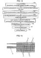
- Fig. 11 is a partial cross-sectional view showing a cable-like piezoelectric element in accordance with a fourth exemplary embodiment of the present invention.
- This piezoelectric element includes core electrode 11 as a first electrode, flexible piezoelectric composition pressure sensitive substance (hereinafter, referred to as pressure sensitive substance) 12, flexible external electrode 13 and protective layer 14 made of an electric insulating elastic body.
- Pressure sensitive substance 12 is formed on the surface of core electrode 11
- external electrode 13 is formed on the surface of pressure sensitive substance 12
- protective layer 14 is formed on the surface of external electrode 13.
- Core electrode 11 and external electrode 13 are insulated from each other by pressure sensitive substance 12.
- Pressure sensitive substance 12 is composed of materials having the similar composition to that in pressure sensitive substance 1 in the first exemplary embodiment.
- External electrode 13 is formed by winding a conductive film on both surfaces of which metal foil is attached, similar to electrodes 2A and 2B in the first exemplary embodiment.
- the conductive film is wound around cable-like pressure sensitive substance 12.
- external electrode 13 may be formed of a conductive layer formed by extrusion molding a flexible conductive composition, or may be formed of a conductive film which is made by coating a conductive coating material (paste).
- External electrode 13 may be formed of a thin vapor-deposited film formed by applying a conductive material on pressure sensitive substance 12 by a method such as vacuum deposition, sputtering, CVD, and the like.
- the conductive material to be used is the same as that in the first exemplary embodiment.
- Protective layer 14 is formed by extrusion molding of the same material as that for protective layer 10 in the third exemplary embodiment.
- piezoelectric ceramic powder 5 described in the first exemplary embodiment is water-repellent treated so as to form covering layer 6 (S17).
- water-repellent treated piezoelectric ceramic powders 3 and organic polymers 4 are kneaded so that water-repellent treated piezoelectric ceramic powders 3 are uniformly mixed and dispersed in organic polymers 4 (S18).
- a titanium coupling agent may be added.
- this kneaded product is processed by using a roll processor, so as to form a sheet-like pressure sensitive substance (S19).
- This sheet-like piezoelectric composition pressure sensitive substance is processed into a pellet form by using a processor such as a pelletizer (S20).
- a pellet-formed piezoelectric composition pressure sensitive substance is extruded by using a processor of an extrusion mold and a layer of pressure sensitive substance 12 is formed around core electrode 11. That is to say, a layer of pressure sensitive substance 12 is provided around core electrode 11 (S21).
- external electrode 13 is formed (S22).
- an organic polymer having elasticity for example, a thermoplastic elastomer, rubber, and the like
- protective layer 14 is formed by extrusion molding (S23).
- a poling treatment is carried out by applying a direct voltage between core electrode 11 and external electrode 13 in the air or in a silicon oil bath (S24), and thus a cable-like piezoelectric element is formed.
- protective layer 14 may be provided after a poling treatment is carried out.
- the poling treatment (S24) is carried out after protective layer 14 is formed (S23), but the poling treatment may be carried out by using dummy electrodes corresponding to the core electrode and the external electrode after a layer of pressure sensitive substance 12 is formed around core electrode 11 (S21), or it may be carried out after external electrode 13 is formed (S22).
- the cable-like piezoelectric element In the thus formed cable-like piezoelectric element, protective layer 14 and pressure sensitive substance 12 are removed and core electrode 11 and external electrode 13 are exposed at one end. Thereby, the cable-like piezoelectric element is connected to a control circuit and used as a pressure sensitive sensor.
- piezoelectric ceramic powders 5 can be reduced. That is to say, covering layer 6 suppresses absorption of water by piezoelectric ceramic powders 5. Therefore, as in the first exemplary embodiment, the changes in the electric property, piezoelectric property and mechanical strength of a cable-like piezoelectric element are reduced. Thus, a cable-like piezoelectric element having excellent durability and reliability can be obtained.
- each particle can be provided with a water-repellent effect. Therefore, even when a cable-like piezoelectric element having a long length of several kilometers or more is processed, any parts in the cable can have the water-repellent effect. Thus, stable water-repellent effect can be always obtained.
- the piezoelectric ceramic powder As the piezoelectric ceramic powder, a solid solution of bismuth sodium titanate and barium titanate, (Bi 1/2 Na 1/2 ) 0.85 Ba 0.15 TiO 3 , which have an average particle diameter of about 1 ⁇ m, and a solid solution of lead titanate and lead zirconate, Pb (Zr ⁇ Ti)O 3 , which have an average particle diameter of about 1 ⁇ m, are used.
- water-repellent material calcium oleate (fatty acid salt) and heptadeca1luorodecyltrichlorosilane (silane compound) are used respectively, and a water-repellent treatment is carried out in the same manner as in the first exemplary embodiment so as to form covering layer 6 on the surface of each piezoelectric ceramic powder.
- these water-repellent treated piezoelectric ceramic powders 3 and chlorinated polyethylene are mixed so that the former is about 60 volume % and the latter is about 35 volume %, respectively.
- the titanium coupling agent isopropoxytriisostearoyl titanate is added and kneaded by using a roller.
- a sheet of the piezoelectric composition pressure sensitive substance is formed in this way, followed by forming pellets by using a pelletizer.
- core electrode 11 is formed by winding a copper foil around a convergence line composed of a large number of polyester fibers of 0.45-mm diameter. Then, with pellets of a piezoelectric composition pressure sensitive substance, pressure sensitive substance 12 is coated around core electrode 11 to the thickness of about 0.6 mm by using an extrusion molding machine.
- a conductive film in which an aluminum foil having a width of 3 mm and a thickness of 10 ⁇ m is attached onto the both surfaces of a polymer film of polyethylene terephthalate having a width of 3 mm and a thickness of 12 ⁇ m, is formed.
- This conductive film is wound around the surface of pressure sensitive substance 12 so that the conductive film is partially overlapped, so as to form external electrode 13.
- an olefin thermoplastic elastomer is coated around external electrode 13 to the thickness of about 0.5 mm by using an extrusion molding machine so as to form protective layer 14.
- a cable-like piezoelectric element is formed.
- a poling treatment is carried out by applying 5 kV/mm of direct voltage between core electrode 11 and external electrode 13 in the air at 100°C.
- Various cable-like piezoelectric elements formed as mentioned above are adjusted so that the effective length is 150 mm and is subjected to a high-temperature and high-humidity test in a thermo-hygrostat chamber under the conditions of a temperature of 85°C and a relative humidity of 85% for 20 hours. After the test, the electric resistance and the electrostatic capacitance are measured at ordinary temperature and at a frequency of 1 kHz. For comparison, a cable-like piezoelectric element that is not provided with covering layer 6 is formed and the same test is carried out.
- Tables 3 and 4 show the rate of change in the electric resistance and the electrostatic capacitance after the high-temperature and high-humidity test, respectively.
- Table 3 covering layer rate of change in electric resistance (%)
- Table 4 covering layer rate of change in electrostatic capacitance (%)
- the electric resistance of the piezoelectric element is reduced in a high-temperature and high-humidity environment. This is thought to be because components of piezoelectric ceramic powder 5 are dissolved in water. Furthermore, the change in the electric resistance is larger in the piezoelectric element using (Bi 1/2 Na 1/2 ) 0.85 Ba 0.15 TiO 3 for piezoelectric ceramic powder 5 than in that using Pb(Zr ⁇ Ti)O 3 for piezoelectric ceramic powder 5. This shows that alkaline component contained in piezoelectric ceramic powder 5 is easily dissolved in water.
- the initial specific resistance of the piezoelectric element using piezoelectric ceramic powder 5 of Pb(Zr ⁇ Ti)O 3 is about twice as large as that of the piezoelectric element using piezoelectric ceramic powder 5 of (Bi 1/2 Na 1/2 ) 0.85 Ba 0.15 TiO 3 . Therefore, it is shown that the specific resistance of the piezoelectric element using piezoelectric ceramic powder 5 of (Bi 1/2 Na 1/2 ) 0.85 Ba 0.15 TiO 3 is low and is further lowered in a high-temperature and high-humidity environment. When the cable-like piezoelectric element is longer, the electric resistance is further reduced.
- the change in the electrostatic capacitance is also larger in the case where (Bi 1/2 Na 1/2 ) 0.85 Ba 0.15 TiO 3 is used for piezoelectric ceramic powder 5 than in the case where Pb(Zr ⁇ Ti)O 3 is used for piezoelectric ceramic powder 5. This is thought to be because there is a difference in the hygroscopic property of the components contained in piezoelectric ceramic powder 5.
- the piezoelectric property is evaluated as follows. Vibration is excited while changing a load at a constant frequency in a state in which a constant load is applied to a central portion of the cable-like piezoelectric element. An amount of produced charges is calculated from the relation between the voltage generated at that time and the load. The piezoelectric property is evaluated by the calculated amount of produced charges. Table 5 shows the rate of change in the amount of produced charges after 20 hours of the high-temperature and high-humidity test.
- Table 5 covering layer rate of change in amount of produced charges (%) A B not formed 96 65 calcium oleate 14 10 heptadecafluorodecyltrichlorosilane 15 8 A: (Bi 1/2 Na 1/2 ) 0.85 Ba 0.15 TiO 3 B: Pb(Zr ⁇ T ⁇ )O 3
- piezoelectric ceramic powders having different relative permittivities in the cable-like piezoelectric element are shown.
- piezoelectric ceramic powders 5 having different relative permittivities Pb(Zr ⁇ Ti)O 3 , (Bi 1/2 Na 1/2 ) 0.85 Ba 0.15 TiO 3 and NaNbO 3 are used. These materials are water-repellent treated with calcium oleate to form covering layer 6, and piezoelectric ceramic powders 3 are obtained.
- a cable-like piezoelectric element is formed as mentioned above so that water-repellent treated piezoelectric ceramic powders 3 is about 60 volume % and chlorinated polyethylene is about 35 volume %. Then, in order to allow the formed piezoelectric element to express the piezoelectric property, a poling treatment is carried out by applying 5 kV/mm of direct voltage between core electrode 11 and external electrode 13 in the air at 100°C. The thus formed cable-like piezoelectric element is adjusted so that the effective length is 150 mm and the voltage output constant is evaluated.
- Table 6 shows the ratios of voltage output constant of the piezoelectric element using other materials than Pb(Zr ⁇ Ti)O 3 for piezoelectric ceramic powder 5 where voltage output constant of the cable-like piezoelectric element using Pb(Zr ⁇ Ti)O 3 for piezoelectric ceramic powder 5 is defined as a reference.
- a preferable range of the relative permittivity and a mechanism for improving the voltage output constant are the same as those in the first exemplary embodiment.
- Fig. 13 is a partial cross-sectional view showing a cable-like piezoelectric element in accordance with a fifth exemplary embodiment of the present invention.
- the piezoelectric element shown in Fig. 13 is different from the piezoelectric element of the fourth exemplary embodiment in that covering layer 15 made of a water-repellent material is provided on the surface of piezoelectric composition pressure sensitive substance (hereinafter, referred to as pressure sensitive substance) 22.
- the cable-like piezoelectric element of this exemplary embodiment includes core electrode 11, flexible pressure sensitive substance 22, covering layer 15, external electrode 13 and protective layer 14.
- Pressure sensitive substance 22 is formed on the surface of core electrode 11, and covering layer 15 is formed on the surface by carrying out a water-repellent treatment.
- Pressure sensitive substance 22 includes piezoelectric ceramic powders 5 and organic polymers 4. Piezoelectric ceramic powder 5 is not water-repellent treated.
- External electrode 13 is formed on the surface of covering layer 15, and protective layer 14 made of an electric insulating elastic body is formed on the surface of external electrode 13.
- covering layer 15 is formed only on the surface of pressure sensitive substance 22 where external electrode 13 is formed. That is to say, covering layer 15 covers at least a part of the surface of pressure sensitive substance 22.
- piezoelectric ceramic powders 5 shown in Fig. 3 and organic polymers 4 are kneaded (S25). This step is the same as step S6 in the second exemplary embodiment.
- a sheet-like piezoelectric composition pressure sensitive substance is formed by using a roll processor (S26).
- This sheet-like piezoelectric composition pressure sensitive substance is processed into a pellet form by using a processor such as a pelletizer (S27).
- a pellet-formed piezoelectric composition pressure sensitive substance is extruded by using a processor of the extrusion mold to form a layer of pressure sensitive substance 22 around core electrode 11. That is to say, a layer of pressure sensitive substance 22 is provided around core electrode 11 (S28).
- covering layer 15 obtained by carrying out a water-repellent treatment is formed on the surface of pressure sensitive substance 22 (S29).
- Step S29 is similar to step S8 in the second exemplary embodiment.
- external electrode 13 is formed on cable-like pressure sensitive substance 22 (S30). Furthermore, protective layer 14 is formed (S31). Thereafter, a poling treatment is carried out (S32), and a cable-like piezoelectric element is formed. Steps S30, S31 and S32 are the same as S22, S23 and S24 in the fourth exemplary embodiment, respectively. Note here that protective layer 14 may be formed after the poling treatment is carried out.
- the poling treatment (S32) is carried out after protective layer 14 is formed (S31), but the poling treatment may be carried out by using dummy electrodes corresponding to the core electrode and the external electrode after a layer of pressure sensitive substance 22 is formed around core electrode 11 (S28) or after water-repellent treated covering layer 15 is formed (S29). Alternatively, the poling treatment may be carried out after external electrode 13 is formed (S30).
- the cable-like piezoelectric element In the thus formed cable-like piezoelectric element, protective layer 14 and pressure sensitive substance 22 are removed and core electrode 11 and external electrode 13 are exposed at one end. Thereby, the cable-like piezoelectric element is connected to a control circuit and used as a pressure sensitive sensor.
- a cable-like piezoelectric element is formed by using calcium oleate as a water-repellent material, (Bi 1/2 Na 1/2 ) 0.85 Ba 0.15 TiO 3 as piezoelectric ceramic powder 5, and an olefin thermoplastic elastomer as protective layer 14.
- the formed piezoelectric element is subjected to a high-temperature and high-humidity test in the same conditions as in the first exemplary embodiment for 20 hours and the water-repellent effect is evaluated based on the change in the electric resistance at that time.
- a piezoelectric element that is not provided with covering layer 15 and a piezoelectric element which uses a piezoelectric composition pressure sensitive substance formed by adding a water-repellent material to piezoelectric ceramic powder 5 and organic polymer 4 and is not provided with covering layer 15 are formed, and the same evaluation is carried out.
- the electric resistance is measured at a frequency of 1 kHz.
- Table 7 shows the rate of change in the electric resistance after the high-temperature and high-humidity test is carried out. Table 7 part where coating treatment is carried out rate of change in electric resistance (%) none -85 mixed in pressure sensitive substance -83 surface of pressure sensitive substance -42
- Fig. 15 is a partial cross-sectional view showing a cable-like piezoelectric element in accordance with a sixth exemplary embodiment of the present invention.
- the cable-like piezoelectric element shown in Fig. 15 is different from the piezoelectric element in the fifth exemplary embodiment in that covering layer 16 made of a water-repellent material is provided on the surface of external electrode 13 instead of the surface of piezoelectric composition pressure sensitive substance (hereinafter, referred to as pressure sensitive substance) 22.
- the other configurations are the same as those in the fifth exemplary embodiment.
- covering layer 16 is provided on the entire surface of external electrode 13, but covering layer 16 may be provided on a part thereof and a part on which covering layer 16 is not provided may be covered with a water vapor non-permeable film. That is to say, covering layer 16 covers at least a part of the external electrode.
- Fig. 16 illustrates a manufacturing process of a cable-like piezoelectric element in accordance with this exemplary embodiment.
- Step S33 of mixing materials forming pressure sensitive substance 22, step 34 of processing the mixed materials into a sheet, step S35 of further pelletization, and step S36 of coating these pellets onto core electrode 11 to form a layer are the same as steps S25, S26, S27 and S28 in the fifth exemplary embodiment, respectively.
- step S30 in the fifth exemplary embodiment external electrode 13 is formed on cable-like pressure sensitive substance 22 (S37). Then, the surface of external electrode 13 is water-repellent treated to form covering layer 16 (S38). This step is similar to step S29 in the fifth exemplary embodiment.
- protective layer 14 is formed (S39) and a poling treatment is carried out (S40). These steps are the same as steps S31 and S32 in the fifth exemplary embodiment, respectively. That it to say, the manufacturing process of the cable-like piezoelectric element in this exemplary embodiment corresponds to a manufacturing process of the cable-like piezoelectric element in the fifth exemplary embodiment in which order of steps S29 and S30 is reversed. Note here that protective layer 14 may be provided after a poling treatment is carried out.
- the poling treatment (S40) is carried out after protective layer 14 is formed (S39), but a poling treatment may be carried out by using dummy electrodes corresponding to a core electrode and an external electrode after a layer of pressure sensitive substance 22 is formed around core electrode 11, or a polling treatment may be carried out after external electrode 13 is formed (S37), or after water-repellent treated covering layer 16 is formed (S38).
- the cable-like piezoelectric element In the thus formed cable-like piezoelectric element, protective layer 14 and pressure sensitive substance 22 are removed and core electrode 11 and external electrode 13 are exposed at one end. Thereby, the cable-like piezoelectric element is connected to a control circuit and used as a pressure sensitive sensor.
- the cable-like piezoelectric element when manufactured, it is required to be wound up by a roll after external electrode 13 is provided around pressure sensitive substance 22. These are works continuously done.
- a water-repellent treatment process can be provided between the providing of external electrode 13 and the roll winding work. In this way, since the roll winding work can be carried out while the water-repellent treatment is carried out, it is not necessary to change the manufacturing process remarkably. That is to say, since the water-repellent treatment can be carried out with respect to the surface of pressure sensitive substance 22 continuously, the productivity is not impaired.
- a piezoelectric element is produced by using calcium oleate as a water-repellent material and (Bi 1/2 Na 1/2 ) 0.85 Ba 0.15 TiO 3 as a piezoelectric ceramic powder.
- the formed piezoelectric element is subjected to a high-temperature and high-humidity test for 20 hours in the same conditions as in the first exemplary embodiment and the water-repellent effect is evaluated based on the change in the electric resistance at that time.
- the electric resistance is measured at a frequency of 1 kHz.
- Table 8 shows the rate of change in the electric resistance after the high-temperature and high-humidity test is carried out. Table 8 part where coating treatment is carried out rate of change in electric resistance (%) none -85 surface of external electrode -54 surface of protective layer -84
- the piezoelectric element in which covering layer 15 is formed on the surface of external electrode 13 shows the rate of change in the electric resistance of the same level as that of the piezoelectric element in which a water-repellent treatment is not carried out, showing that no water-repellent treatment effect is exhibited.
- external electrode 13 when external electrode 13 is formed by extrusion molding a flexible conductive composition produced by kneading conductive powders and organic polymers, when external electrode 13 is formed by coating a conductive coating material obtained by dispersing electric conductive powders in organic polymers, or when external electrode 13 is formed from conductive materials by vapor deposition such as vacuum deposition, sputtering, CVD, and the like, it has excellent adhesion with respect to pressure sensitive substance 22. Therefore, when a cable-like piezoelectric element is protected by another member, protective layer 14 may not be formed.
- the cable-like piezoelectric elements of the fourth to sixth exemplary embodiments have flexibility and cable shape. Therefore, they can be provided to a place including a bending part or a place with a limited attachment width. Furthermore, they have an excellent property that the electric property, piezoelectric property and mechanical strength are maintained even when they are used in a high-temperature and high-humidity environment. Therefore, such piezoelectric elements are suitable for a sensor to be used outside, a sensor for detecting something caught in an automobile door, and the like, which require such providing conditions or properties.
- the piezoelectric element is used in a configuration in which the cross section of the piezoelectric elements is exposed.
- water vapor infiltrates from a boundary portion between core electrode 11 and pressure sensitive substance 22 exposed to the cross section, and that the water vapor is condensed on the surface of pressure sensitive substance 22 that is brought into contact with the side of core electrode 11.
- second covering layer 23 made of a water-repellent material between core electrode 11 and pressure sensitive substance 22
- third covering layer 24 made of a water-repellent material is formed also on a cut end surface of pressure sensitive substance 22.
- Fig. 17 is based on the configuration of the fifth exemplary embodiment, but similarly may be based on the configuration of the sixth exemplary embodiment.
- an end face of pressure sensitive substance 7 is also covered with a covering layer.
- a covering layer made of a water-repellent material also by increasing a thicknesses of protective layers 10 and 14 to increase the resistance to permeation of water vapor, absorption of water by piezoelectric ceramic powder 5 can be suppressed.
- a dense film through which it is difficult for molecules of water vapor to pass may be formed as a covering layer.
- the dense film formed by physical vapor deposition, chemical vapor deposition or chemical synthetic processing can suppress infiltration of water vapor itself.
- the effect of the elution of piezoelectric ceramic powders 5 or impurities by water can be realized.
- the above-mentioned configuration may be applied to either one of electrodes 2A and 2B side.
- the cable-like piezoelectric elements of the fourth to sixth exemplary embodiments are capable of detecting a large area by providing them on the bed in a meander shape. Furthermore, when maintenance such as washing or folding up are taken into consideration, they have a configuration also suitable for the body motion sensor used for the care bed.
- the present invention is not limited to these exemplary embodiments.
- the piezoelectric element of the present invention can suppress absorption of water by a piezoelectric composition pressure sensitive substance even when it is used in a high-temperature and high-humidity environment, changes in the electric property, piezoelectric property and mechanical tensile strength are small. That is to say, the piezoelectric element has excellent durability and reliability. Therefore, it is suitable for the use in a high-temperature and high-humidity environment, for example, for the outdoor use. It can be applied for a wide variety of uses in a pressure sensitive sensor for preventing something from being caught in a door or window of automobile, or a sensor for detecting a user's body motion on a care bed and judging where or not a user is present on the bed.
Landscapes
- Engineering & Computer Science (AREA)
- Physics & Mathematics (AREA)
- General Physics & Mathematics (AREA)
- Chemical & Material Sciences (AREA)
- Composite Materials (AREA)
- Materials Engineering (AREA)
- Manufacturing & Machinery (AREA)
- Compositions Of Macromolecular Compounds (AREA)
Applications Claiming Priority (7)
| Application Number | Priority Date | Filing Date | Title |
|---|---|---|---|
| JP2004313573 | 2004-10-28 | ||
| JP2004313575 | 2004-10-28 | ||
| JP2004313572 | 2004-10-28 | ||
| JP2005169141 | 2005-06-09 | ||
| JP2005169140 | 2005-06-09 | ||
| JP2005169139 | 2005-06-09 | ||
| PCT/JP2005/014184 WO2006046341A1 (fr) | 2004-10-28 | 2005-08-03 | Élément piézoélectrique et procédé de fabrication dudit élément |
Publications (1)
| Publication Number | Publication Date |
|---|---|
| EP1806568A1 true EP1806568A1 (fr) | 2007-07-11 |
Family
ID=36227593
Family Applications (1)
| Application Number | Title | Priority Date | Filing Date |
|---|---|---|---|
| EP05768444A Withdrawn EP1806568A1 (fr) | 2004-10-28 | 2005-08-03 | Élément piézoélectrique et procédé de fabrication dudit élément |
Country Status (5)
| Country | Link |
|---|---|
| US (1) | US7467558B2 (fr) |
| EP (1) | EP1806568A1 (fr) |
| KR (1) | KR100723357B1 (fr) |
| CA (1) | CA2552972A1 (fr) |
| WO (1) | WO2006046341A1 (fr) |
Cited By (3)
| Publication number | Priority date | Publication date | Assignee | Title |
|---|---|---|---|---|
| WO2011104295A1 (fr) * | 2010-02-24 | 2011-09-01 | Belenos Clean Power Holding Ag | Récipient composite d'auto-surveillance pour des milieux sous haute pression |
| EP2161766A3 (fr) * | 2008-09-03 | 2012-07-25 | Robert Bosch GmbH | Convertisseur piézoélectrique et son procédé de fabrication |
| EP2821766A1 (fr) * | 2013-06-18 | 2015-01-07 | Robert Bosch Gmbh | Dispositif de détection |
Families Citing this family (25)
| Publication number | Priority date | Publication date | Assignee | Title |
|---|---|---|---|---|
| JP4852850B2 (ja) * | 2005-02-03 | 2012-01-11 | セイコーエプソン株式会社 | 圧電振動素子、圧電振動子、圧電発振器、周波数安定化方法、及び圧電振動子の製造方法 |
| JP4497370B2 (ja) * | 2005-05-31 | 2010-07-07 | 日本碍子株式会社 | 微小物体の飛翔状態検出装置、及び微小物体の飛翔状態検出方法 |
| JP5568206B2 (ja) * | 2006-09-15 | 2014-08-06 | 東海ゴム工業株式会社 | 変形センサ |
| US7411338B1 (en) * | 2007-01-30 | 2008-08-12 | Raytheon Company | Structural material with piezoelectric material particles |
| US7886621B2 (en) * | 2009-03-06 | 2011-02-15 | University Of South Australia | Digital foam |
| JP5114463B2 (ja) * | 2009-09-25 | 2013-01-09 | 日立オートモティブシステムズ株式会社 | 発熱抵抗式空気流量測定装置 |
| JP5616171B2 (ja) * | 2009-09-28 | 2014-10-29 | 富士フイルム株式会社 | 高分子複合圧電体及びそれを用いた圧電素子 |
| US8783099B2 (en) * | 2011-07-01 | 2014-07-22 | Baker Hughes Incorporated | Downhole sensors impregnated with hydrophobic material, tools including same, and related methods |
| KR101628584B1 (ko) * | 2011-09-30 | 2016-06-08 | 후지필름 가부시키가이샤 | 전기 음향 변환 필름, 플렉시블 디스플레이, 성대 마이크로폰 및 악기용 센서 |
| US9112432B2 (en) * | 2012-12-14 | 2015-08-18 | Samsung Electronics Co., Ltd. | Piezoelectric generator and method of manufacturing the same |
| JP2014215530A (ja) * | 2013-04-26 | 2014-11-17 | ソニー株式会社 | ポリマー素子およびその製造方法、並びにカメラモジュールおよび撮像装置 |
| WO2015061726A1 (fr) * | 2013-10-25 | 2015-04-30 | Board Of Regents, The University Of Texas System | Procédé de fabrication de capteur de pression |
| TW201545828A (zh) * | 2014-06-10 | 2015-12-16 | Ya-Yang Yan | 一種放電加工切割線及該放電加工切割線之製造方法 |
| KR101620296B1 (ko) * | 2014-08-29 | 2016-05-13 | (주)와이솔 | 적층형 압전 세라믹 소자 |
| CN107924986B (zh) * | 2015-07-16 | 2021-02-23 | 住友理工株式会社 | 压电传感器 |
| US10948366B2 (en) * | 2016-10-04 | 2021-03-16 | Arizona Board Of Regents On Behalf Of Arizona State University | Flexible sensors incorporating piezoresistive composite materials and fabrication methods |
| FR3060857A1 (fr) * | 2016-12-20 | 2018-06-22 | Compagnie Generale Des Etablissements Michelin | Composites piezoelectriques en matrice souple |
| US11737366B2 (en) | 2017-03-01 | 2023-08-22 | Rogers Corporation | Layered sensor apparatus and method of making same |
| CN110462858B (zh) * | 2017-03-28 | 2023-12-05 | Tdk株式会社 | 压电组合物及压电元件 |
| US11552240B2 (en) | 2017-10-24 | 2023-01-10 | Purdue Research Foundation | Machines and processes for producing polymer films and films produced thereby |
| CN110459672B (zh) * | 2019-07-17 | 2023-01-03 | 深圳航天科技创新研究院 | 一种压电陶瓷传感器及其制备方法 |
| US11486783B2 (en) * | 2020-09-25 | 2022-11-01 | Apple Inc. | Stand-alone water detector |
| KR102610162B1 (ko) * | 2020-11-10 | 2023-12-04 | 전북대학교산학협력단 | 압전물질 복합체, 이의 필름과 제조방법, 및 이 필름을 이용한 센서 |
| CN114087967B (zh) * | 2021-11-15 | 2023-03-14 | 浙江大学 | 一种基于后屈曲压电效应的结构位移自供能传感器 |
| CN117737676B (zh) * | 2024-02-19 | 2024-04-16 | 中国科学院长春光学精密机械与物理研究所 | Mim电容器中绝缘体薄膜及其制备方法 |
Family Cites Families (14)
| Publication number | Priority date | Publication date | Assignee | Title |
|---|---|---|---|---|
| US3624465A (en) * | 1968-06-26 | 1971-11-30 | Rca Corp | Heterojunction semiconductor transducer having a region which is piezoelectric |
| US3985658A (en) * | 1975-04-16 | 1976-10-12 | The United States Of America As Represented By The United States Energy Research And Development Administration | Extinguishing agent for combustible metal fires |
| US4786837A (en) * | 1987-05-05 | 1988-11-22 | Hoechst Celanese Corporation | Composite conformable sheet electrodes |
| US4932414A (en) * | 1987-11-02 | 1990-06-12 | Cornell Research Foundation, Inc. | System of therapeutic ultrasound and real-time ultrasonic scanning |
| JPH0389799A (ja) * | 1989-09-01 | 1991-04-15 | Matsushita Electric Ind Co Ltd | 圧電発音体 |
| EP0736915A1 (fr) * | 1995-04-03 | 1996-10-09 | Seiko Epson Corporation | Couche mince piézoélectrique, procédé de fabrication, et tête d'enregistrement à jet d'encre utilisant cette couche mince |
| JPH09181558A (ja) * | 1995-12-27 | 1997-07-11 | Kyocera Corp | 圧電素子及び樹脂封止型圧電部品 |
| US5998525A (en) * | 1996-12-02 | 1999-12-07 | Fmc Corporation | Coating and composition for transportation and sign surfaces and method of preparing and applying same |
| US6364450B1 (en) * | 1999-08-03 | 2002-04-02 | Canon Kabushiki Kaisha | Color filter manufacturing method and apparatus, display device manufacturing method, method of manufacturing apparatus having display device, and display device panel manufacturing method and apparatus |
| JP3516030B2 (ja) * | 2000-04-25 | 2004-04-05 | 花王株式会社 | 包装体のシール装置 |
| JP4674405B2 (ja) * | 2000-11-21 | 2011-04-20 | Tdk株式会社 | 圧電磁器 |
| JP2003106910A (ja) * | 2001-09-28 | 2003-04-09 | Matsushita Electric Ind Co Ltd | 圧力センサおよびその製造方法 |
| JP2003176390A (ja) * | 2002-09-04 | 2003-06-24 | Matsushita Electric Ind Co Ltd | 圧電組成物感圧体、これを用いた感圧素子及びこの感圧素子を用いた圧力検知装置 |
| EP1672443B1 (fr) * | 2004-12-17 | 2010-08-18 | ETA SA Manufacture Horlogère Suisse | Montre comportant un capteur de pression |
-
2005
- 2005-08-03 EP EP05768444A patent/EP1806568A1/fr not_active Withdrawn
- 2005-08-03 WO PCT/JP2005/014184 patent/WO2006046341A1/fr not_active Ceased
- 2005-08-03 KR KR1020067003964A patent/KR100723357B1/ko not_active Expired - Fee Related
- 2005-08-03 CA CA002552972A patent/CA2552972A1/fr not_active Abandoned
- 2005-08-03 US US10/570,709 patent/US7467558B2/en not_active Expired - Fee Related
Non-Patent Citations (1)
| Title |
|---|
| See references of WO2006046341A1 * |
Cited By (5)
| Publication number | Priority date | Publication date | Assignee | Title |
|---|---|---|---|---|
| EP2161766A3 (fr) * | 2008-09-03 | 2012-07-25 | Robert Bosch GmbH | Convertisseur piézoélectrique et son procédé de fabrication |
| WO2011104295A1 (fr) * | 2010-02-24 | 2011-09-01 | Belenos Clean Power Holding Ag | Récipient composite d'auto-surveillance pour des milieux sous haute pression |
| CN102770574A (zh) * | 2010-02-24 | 2012-11-07 | 贝伦诺斯清洁电力控股有限公司 | 用于高压介质的自监测复合容器 |
| US9618413B2 (en) | 2010-02-24 | 2017-04-11 | Belanos Clean Power Holding AG | Self-monitoring composite vessel for high pressure media |
| EP2821766A1 (fr) * | 2013-06-18 | 2015-01-07 | Robert Bosch Gmbh | Dispositif de détection |
Also Published As
| Publication number | Publication date |
|---|---|
| US7467558B2 (en) | 2008-12-23 |
| CA2552972A1 (fr) | 2006-04-28 |
| US20070186689A1 (en) | 2007-08-16 |
| KR20060086355A (ko) | 2006-07-31 |
| WO2006046341A1 (fr) | 2006-05-04 |
| KR100723357B1 (ko) | 2007-05-30 |
Similar Documents
| Publication | Publication Date | Title |
|---|---|---|
| US7467558B2 (en) | Piezoelectric element comprising a covering layer that suppresses the absorption of water and method of manufacturing the same | |
| EP1044466B1 (fr) | Materiau piezo-electrique et dispositifs associes perfectionnes obtenus a partir de ceramiques dispersees dans des polymeres | |
| US11014268B2 (en) | 3D printing of piezoelectric ceramic particle/fluoropolymer nanocomposites with in-situ poling for sensor applications | |
| US7378040B2 (en) | Method of forming fluoropolymer binders for carbon nanotube-based transparent conductive coatings | |
| KR100562598B1 (ko) | 압전 수지 조성물, 압력 센서, 압전 케이블, 압력 및 온도 검출용 케이블, 압력 및 온도 검출 장치 | |
| US20150202656A1 (en) | Flexible transducer | |
| Park et al. | Actuating single wall carbon nanotube–polymer composites: intrinsic unimorphs | |
| US20050209392A1 (en) | Polymer binders for flexible and transparent conductive coatings containing carbon nanotubes | |
| KR20160016385A (ko) | 적층 세라믹 커패시터 | |
| KR101285415B1 (ko) | 압전 복합 소재 | |
| KR20200112033A (ko) | 투명 유연 전극/전자파 차폐 필름 및 이의 제조방법 | |
| US11479647B2 (en) | Film including a fluoropolymer | |
| US10745531B2 (en) | Film | |
| JP2008160045A (ja) | 可撓性感圧体とそれを用いた圧電素子およびその製造方法 | |
| WO2007024206A2 (fr) | Liant fluoropolymere pour revetements conducteurs transparents a base de nanotubes de carbone | |
| JP2008192672A (ja) | ケーブル状圧電素子 | |
| JP2008192671A (ja) | 圧電素子 | |
| JP2007017420A (ja) | 圧電素子とその製造方法 | |
| JP2009020032A (ja) | 圧力検出素子 | |
| JP2007017421A (ja) | ケーブル状圧電素子とその製造方法 | |
| Liu et al. | Investigation of polymer-coated nano silver/polyurethane nanocomposites for electromechanical applications | |
| EP1387416A2 (fr) | Composant à couche piézoélectrique/électrostrictive | |
| JP2009103484A (ja) | 圧電組成物感圧体を用いた圧電素子 | |
| JP2008186985A (ja) | 圧電素子 | |
| JP2008151638A (ja) | ケーブル状圧力センサ |
Legal Events
| Date | Code | Title | Description |
|---|---|---|---|
| PUAI | Public reference made under article 153(3) epc to a published international application that has entered the european phase |
Free format text: ORIGINAL CODE: 0009012 |
|
| 17P | Request for examination filed |
Effective date: 20060306 |
|
| RBV | Designated contracting states (corrected) |
Designated state(s): AT BE BG CH CY CZ DE DK EE ES FI FR GB GR HU IE IS IT LI LT LU LV MC NL PL PT RO SE SI SK TR |
|
| DAX | Request for extension of the european patent (deleted) | ||
| RAP1 | Party data changed (applicant data changed or rights of an application transferred) |
Owner name: PANASONIC CORPORATION |
|
| STAA | Information on the status of an ep patent application or granted ep patent |
Free format text: STATUS: THE APPLICATION HAS BEEN WITHDRAWN |
|
| 18W | Application withdrawn |
Effective date: 20090916 |