EP1813737A2 - Dachdurchgang und Verfahren zu seiner Herstellung - Google Patents
Dachdurchgang und Verfahren zu seiner Herstellung Download PDFInfo
- Publication number
- EP1813737A2 EP1813737A2 EP06126953A EP06126953A EP1813737A2 EP 1813737 A2 EP1813737 A2 EP 1813737A2 EP 06126953 A EP06126953 A EP 06126953A EP 06126953 A EP06126953 A EP 06126953A EP 1813737 A2 EP1813737 A2 EP 1813737A2
- Authority
- EP
- European Patent Office
- Prior art keywords
- roof
- collar
- adapter ring
- feed
- ring
- Prior art date
- Legal status (The legal status is an assumption and is not a legal conclusion. Google has not performed a legal analysis and makes no representation as to the accuracy of the status listed.)
- Granted
Links
Images



Classifications
-
- E—FIXED CONSTRUCTIONS
- E04—BUILDING
- E04D—ROOF COVERINGS; SKY-LIGHTS; GUTTERS; ROOF-WORKING TOOLS
- E04D1/00—Roof covering by making use of tiles, slates, shingles, or other small roofing elements
- E04D1/30—Special roof-covering elements, e.g. ridge tiles, gutter tiles, gable tiles, ventilation tiles
-
- F—MECHANICAL ENGINEERING; LIGHTING; HEATING; WEAPONS; BLASTING
- F24—HEATING; RANGES; VENTILATING
- F24F—AIR-CONDITIONING; AIR-HUMIDIFICATION; VENTILATION; USE OF AIR CURRENTS FOR SCREENING
- F24F7/00—Ventilation
- F24F7/02—Roof ventilation
-
- E—FIXED CONSTRUCTIONS
- E04—BUILDING
- E04D—ROOF COVERINGS; SKY-LIGHTS; GUTTERS; ROOF-WORKING TOOLS
- E04D1/00—Roof covering by making use of tiles, slates, shingles, or other small roofing elements
- E04D1/30—Special roof-covering elements, e.g. ridge tiles, gutter tiles, gable tiles, ventilation tiles
- E04D2001/307—Special roof-covering elements, e.g. ridge tiles, gutter tiles, gable tiles, ventilation tiles for passages in the roof surface
-
- E—FIXED CONSTRUCTIONS
- E04—BUILDING
- E04D—ROOF COVERINGS; SKY-LIGHTS; GUTTERS; ROOF-WORKING TOOLS
- E04D1/00—Roof covering by making use of tiles, slates, shingles, or other small roofing elements
- E04D1/30—Special roof-covering elements, e.g. ridge tiles, gutter tiles, gable tiles, ventilation tiles
- E04D2001/309—Ventilation tiles
Definitions
- the invention relates to a roof passage and a method for its production according to the preambles of claims 1 and 12.
- a roof is usually covered with roof tiles, the adjacent in a first-parallel row roof tiles are connected to each other via their cover and Wasserfalze, while cover the roof tiles laid in a ridge eaves line scaly.
- a closed, rain-proof roof skin for the implementation of so-called rising components, such as fume pipes, antennas, exhaust pipes or the like, must be interrupted.
- so-called roof passages are used, which each have a cover and a water fold at their two longitudinal edges and are provided at their head or foot-side edge with hooking noses or support ribs. In this way, the roof passages can be optimally integrated when laying the roof tiles.
- a roof passage In its central region, a roof passage is usually provided with a passage opening through which the rising component is guided to the outside.
- the roof passage also has in the center an attachment which, on the one hand, guides the rising component and, on the other hand, shields the passage opening in a rainproof manner.
- a roof sealing plate for attachment of antennas and roof posts which consists of an elastic plastic ( DE 1779171 U ).
- This plastic preferably polyethylene or polyvinyl chloride, is molded and is provided with a cone. The tip of the cone can be separated so that the antennas of different diameters can be passed.
- vent cap including a tube provided with outlet slots near its upper end ( DE 18 46 788 U ). No standardized attachments can be attached to the vent attachment.
- vent pipe ventilation device for sloping building roofs is known ( DE 90 04 653 U1 ). This venting device is not suitable for attaching essays.
- Another known device has an outlet pipe, a sealing ring and a connecting pipe ( DE 198 06 712 C1 ). This device has no adapter ring.
- a ventilation device for a pitched roof which has a base plate with an outlet nozzle arranged on its upper side and the outlet nozzle Covering cover has ( DE 39 14 025 A1 ).
- the base plate is flat and has a greater width than a roof tile.
- a vent pipe which has a pipe section which forms at a top end a vent opening protected by a cap and is open at the other end ( DE 20 2004 009 235 U1 ). Between the cap and the other end of the pipe piece of a wegnellr this flange is provided.
- the roof passage is made of plastic by injection molding and executed the shape of a roof tile accordingly. It consists of two shells, the lower shell has a connection piece for a vent pipe and the upper shell is provided with a trained as a dome attachment for a vent pipe.
- the base plate designed as a roof plate with a feed-through collar on which a bellows-like hood collar can be fastened, through which a vent tube is guided to the outside.
- the base plate can be made of plastic or concrete.
- roof passages with attachments adaptable to the roof inclination are in DE 7411996U and DE 7412053U described.
- the roof passages have a roof pan provided with an insertion opening, in which the insertion opening is surrounded by a bushing collar.
- the attachment has the form of a ventilation pipe or antenna passage and covers the bushing collar of the roof tile.
- roof passages by injection molding are relatively expensive, on the one hand due to the high cost of materials and on the other hand due to the large-sized injection molds. If the roof passages, however, made of concrete, so attaching a bushing collar represents a significant manufacturing and processing costs.
- the object of the invention is to provide an optimally integrated in the roof surface roof passage, which is inexpensive and easy to manufacture and also suitable for attaching different essays.
- the invention thus relates to a roof passage and a method for its production.
- the roof passage has a roof tile, which is provided for example by means of a jet of water with a hole. Through this hole a feed-through collar of an adapter ring is pushed.
- the feed-through collar has a ring whose contour is adapted to the contour of the roof tile.
- fixing elements are attached to it provided, with which it can be positioned on the roof tile. Standardized attachments can be connected to the adapter ring.
- a conventional roof tile made of concrete or clay is used, in the subsequently introduced the insertion opening.
- This can be done, for example, with a cut-off machine or with a high-pressure water jet.
- Expensive injection molds for the production of an integratable into the roof surface base plate - as they are required in the known roof passages - are therefore not required.
- the feed-through collar is arranged on the adapter ring, and the adapter ring can be placed flat with its adapted to the surface contour of the roof outer ring on the top of the roof tile. In this way, the manual production of roof tiles with a surrounding the insertion opening implementing collar is unnecessary.
- a connecting means for example.
- a one-component adhesive or butyl adhesive applied to the outer ring. After inserting the adapter ring into the insertion opening, it is no longer necessary to wait for curing of the bonding agent, because the adapter ring is held by the fixing elements in position, so that incurred in production no waiting and additional processing costs.
- the desired attachment can be mounted on the adapter ring immediately, and the ready-made roof passage can be supplied to the packaging.
- the essays used to make the roof passage may be formed, for example, as an antenna passage, Sanilcomparativelyer, exhaust pipe passage or the like.
- the various attachments are standardized with respect to the range connectable to the adapter ring, so that the different attachments are always compatible with the adapter ring. In this way, the roof passage can be designed according to market demand.
- the assembly of the roof passage is facilitated by the fact that the adapter ring has latching elements with which the attachments can be firmly fixed to the adapter ring.
- a particularly reliable connection results when the latching elements of the adapter ring interact with counter-elements on the standardized attachments.
- the counter-elements can be designed lashing or Kunststoffförmig.
- Fig. 1 is a side perspective view of an adapter ring 1 is shown for the attachment of standardized essays on a roof tile, wherein a standardized attachment is not shown.
- the adapter ring 1 has a feed-through opening 2 surrounding a feed-through collar 3, on whose outer side 4, an outer ring 5 is arranged. At the arranged under the outer ring 5 section 6 of the feed-through collar 3 a plurality of fixing elements 7, 8, 9 are mounted.
- the feed-through collar 3 may have the shape of an ellipse in cross-section, but also be circular or n-shaped.
- an inner ring 11 is arranged, wherein below this inner ring 11 a plurality of latching elements are mounted, of which only the latching elements 12, 13 can be seen.
- FIG. 2 shows a front view of the adapter ring 1 according to FIG. 1, viewed in the direction A according to FIG. 1.
- the feed-through collar 3 with the outer ring 5, which divides the feed-through collar 3 into an upper section 15 and a lower section 6, can again be seen ,
- the adapter ring 1 On the sides of the lower portion 6, the adapter ring 1 has a plurality of opposing fixing elements 9, 14. These fixing elements 9, 14 serve to fix the adapter ring 1 to a roof tile, not shown here, wherein the adapter ring 1 is inserted into a recessed into the roof insert opening, so that the roof tile at least partially in the area 16, 17, d. H. between the fixing elements 9, 14 and the outer ring 5 is arranged.
- the inner ring 11 and the outer ring 5 arranged on the feedthrough collar 3 can be seen.
- Above the inner ring 11, four latching elements 12, 13, 20, 21 can be seen on the feedthrough collar 3.
- These latching elements 12, 13, 20, 21 serve to enter into a fixed connection with specially provided counter-elements on a standardized attachment. A slipping of the essay, which is not shown here, is therefore no longer possible.
- latching elements 12, 13, 20, 21 are preferably arranged symmetrically on the feedthrough collar 3, and an odd number of latching elements arranged on the feedthrough collar 3 is also conceivable.
- the side 22 of the outer ring 5 shown here is provided with adhesive 32. Since the adapter ring 1 rests with the side 22 of the outer ring 5 on the top of the roof tile, the adapter ring 1 is connected not only via the fixing elements 7 to 9, 14, 18, 19, but also by means of the adhesive fixed to the roof tile. The adhesive also causes a watertight connection between the adapter ring 1 and the roof tile.
- the adapter ring 1 is fastened to the roof tile via the fixing elements 7 to 9, 14, 18, 19, it is not necessary to temporarily store the roof tile with the adapter ring 1 attached to it, so that the adhesive 32 hardens, but the roof tile with the adapter ring 1 can be used directly to cover the roof.
- the adhesive 32 can thus harden after installation of the roof tile in the roof.
- the fixing 7 to 9, 14, 18, 19 thus fulfill two functions. On the one hand they stabilize the adapter ring 1 with a standardized attachment attached to it, and on the other hand they relieve the adhesive 32.
- FIG. 4 shows a perspective view of the adapter ring 1 inserted into an insertion opening of a roof tile 23.
- an insertion opening is cut into the roof tile 23, for example with a high-pressure water jet.
- This insertion opening preferably has a size which ensures that the adapter ring 1 at least partially rests with the outer ring 5 on the roof pan 23 and that on the other hand the adapter ring 1 via the fixing elements 7 to 9, 14, 18, 19 in the roof tile 23rd is fixed.
- the adapter ring 1 is located so that the entire side 22 of the outer ring 5 is in extensive contact with the roof tile 23.
- the adapter ring 1 for a shape which is adapted to the surface contour of the roof tile 23, thereby ensuring that the outer ring 5 is in any position with the roof tile 23 in contact.
- Fig. 5 is a section BB through the recessed into the roof pan 23 adapter ring 1 shown in FIG. 4.
- the inner ring 11 with the latching elements 13, 20 arranged underneath can be seen, with the latching elements 13, 20 facing one another.
- the feed-through collar 3 has, as can be seen here again, a shape adapted to the surface contour of the roof tile 23.
- the roof tile which is only partially shown here, is enclosed between the outer ring 5 and the fixing elements, wherein only the fixing elements 8, 18 can be seen.
- the distance between the side 22 of the outer ring 5 and the fixing elements 8, 18 corresponds approximately to the thickness of the roof pan 23.
- a waterproof adhesive connection 23a is shown between the resting on the top of the roof pan 23 outer ring 5 and the roof tile.
- the adapter ring 1 consists of a material, for. As plastic, which has a certain flexibility.
- the flexibility should preferably be so great in the lower section 6 of the feed-through collar 3 that the fixing elements 8, 18 of this lower section 6 do not break off when the feed-through collar 3 is inserted into the insertion opening of the roof tile 23. It must therefore be ensured that the fixing elements 8, 18 during insertion of the lower portion 6 of the feed-through collar 3 can be pressed in the direction of the passage opening 2, to then move back outwardly so as to the roof pan 23 together with the outer ring 5 enclose.
- Fig. 6 an exploded view of a roof passage is shown, which consists of a roof tile 23 and the adapter ring 1 according to FIG. 4 and can be joined together with a standardized attachment 25. You can see the roof tile 23 with the cut insert opening 24 and the adapter ring. 1
- the feed-through collar 3 of the adapter ring 1 carries in the lower portion 6, the fixing elements 7 to 9, 14, 18, 19. Also visible is the outer ring 5, which is provided on its underside with an adhesive and placed on the roof tile 23. The lower portion 6 of the feed-through collar 3 is guided through the insertion opening 24, so that the adapter ring 1 is fastened by means of the fixing elements 7 to 9, 14, 18, 19 on the roof tile 23.
- the standardized attachment 25 is shown, wherein the attachment 25 is a ventilation element with a hood 26 and a tube 27 which can be passed through the passage opening 2 of the implementation collar 3.
- the standardized attachment 25 can be fixedly connected to the latching elements 12, 13, 20, 21 arranged on the adapter ring 1.
- an insert opening 24 is cut into the roof tile 23.
- an adhesive 32 is applied to the side 22 of the outer ring 5 and the adapter ring 1 is then inserted with the lower portion 6 of the grommet 3 in the insertion opening 24 until the outer ring 5 rests with its side 22 on the roof tile 23, so that a large-area and waterproof adhesive bond arises.
- the roof tile 23 is positioned between the outer ring 5 and the fixing elements 7 to 9, 14, 18, 19.
- the standardized attachment 25 is placed on the adapter ring 1.
- the attachment 25 is only then firmly arranged on the adapter ring 1 when the latching elements 12, 13, 20, 21 have engaged in the counter-elements 28, 29.
Landscapes
- Engineering & Computer Science (AREA)
- Architecture (AREA)
- Civil Engineering (AREA)
- Structural Engineering (AREA)
- Chemical & Material Sciences (AREA)
- Combustion & Propulsion (AREA)
- Mechanical Engineering (AREA)
- General Engineering & Computer Science (AREA)
- Roof Covering Using Slabs Or Stiff Sheets (AREA)
- Building Environments (AREA)
- Press-Shaping Or Shaping Using Conveyers (AREA)
Abstract
Description
- Die Erfindung betrifft einen Dachdurchgang und ein Verfahren zu seiner Herstellung nach den Oberbegriffen der Patentansprüche 1 und 12.
- Ein Dach wird üblicherweise mit Dachpfannen eingedeckt, wobei die in einer firstparallelen Reihe benachbarten Dachpfannen jeweils über ihre Deck- und Wasserfalze miteinander verbunden sind, während sich die in einer First-Trauf-Linie verlegten Dachpfannen schuppenartig überdecken. Auf diese Weise entsteht eine geschlossene, regendichte Dachhaut, die jedoch zur Durchführung von so genannten aufgehenden Bauteilen, wie beispielsweise Dunstrohren, Antennen, Abgasleitungen oder dergleichen, unterbrochen werden muss. Um die Gefahr von Undichtigkeiten gering zu halten, verwendet man so genannte Dachdurchgänge, die an ihren beiden Längsrändern jeweils einen Deck- und einen Wasserfalz aufweisen und an ihrem kopf- bzw. fußseitigen Rand mit Einhängenasen bzw. Auflagerippen versehen sind. Auf diese Weise lassen sich die Dachdurchgänge beim Verlegen der Dachpfannen optimal integrieren.
- In ihrem mittigen Bereich ist ein Dachdurchgang üblicherweise mit einer Durchgangsöffnung versehen, durch die das aufgehende Bauteil nach außen geführt wird. Der Dachdurchgang weist mittig zudem einen Aufsatz auf, der einerseits das aufgehende Bauteil führt und anderseits die Durchgangsöffnung regensicher abschirmt.
- Bekannt ist eine Dachabdichtungsplatte zur Anbringung von Antennen und Dachständern, die aus einem elastischen Kunststoff besteht (
DE 1779171 U ). Dieser Kunststoff, vorzugsweise Polyethylen oder Polyvinylchlorid, wird formgespritzt und ist mit einem Konus versehen. Die Spitze des Konus kann abgetrennt werden, so dass die Antennen unterschiedlichen Durchmessers hindurchgeführt werden können. - Es ist auch ein Entlüftungsaufsatz bekannt, der ein Rohr enthält, das in der Nähe seines oberen Endes mit Auslassschlitzen versehen ist (
DE 18 46 788 U ). Auf dem Entlüftungsaufsatz können keine standardisierten Aufsätze angebracht werden. - Weiterhin ist eine Dunstrohr-Entlüftungsvorrichtung für schräge Gebäudedächer bekannt (
DE 90 04 653 U1 ). Auch diese Entlüftungsvorrichtung ist nicht für das Anbringen von Aufsätzen geeignet. - Eine andere bekannte Vorrichtung weist ein Auslassrohr, einen Dichtring und ein Anschlussrohr auf (
DE 198 06 712 C1 ). Diese Vorrichtung besitzt keinen Adapterring. - Ferner ist eine Lüftungsvorrichtung für ein Schrägdach bekannt, die eine Grundplatte mit einem auf deren Oberseite angeordneten Austrittsstutzen und eine den Austrittsstutzen abdeckende Abdeckhaube aufweist (
DE 39 14 025 A1 ). Dabei ist die Grundplatte flach ausgeführt und weist eine größere Breite als ein Dachstein auf. - Bei einem weiteren bekannten Entlüftungselement zur Verwendung auf Gebäudedächern ist ein Dunstrohr vorgesehen, das ein Rohrstück aufweist, welches an einem oberen Ende eine durch eine Kappe geschützte Entlüftungsöffnung bildet und am anderen Ende offen ist (
DE 20 2004 009 235 U1 ). Zwischen der Kappe und dem anderen Ende des Rohrstücks ist ein von diesem wegstehender Flansch vorgesehen. - Ein zwischen die Dachpfannen integrierbarer Dachdurchgang ist aus der
WO 93/02262 - In der
DE 101 32 934 A1 ist ein weiterer Dachdurchgang beschrieben, der eine als Dachpfanne ausgebildete Grundplatte mit einem Durchführungskragen aufweist, an dem ein faltenbalgähnliches Haubenkragen befestigbar ist, durch den ein Entlüftungsrohr nach außen geführt ist. Die Grundplatte kann aus Kunststoff oder Beton bestehen. - Weitere Dachdurchgänge mit an die Dachneigung anpassbaren Aufsätzen sind in
DE 7411996U undDE 7412053U beschrieben. Die Dachdurchgänge weisen eine mit einer Einsatzöffnung versehene Dachpfanne auf, bei der die Einsatzöffnung von einem Durchführungskragen umgeben ist. Der Aufsatz besitzt die Form eines Lüftungsrohres oder Antennendurchgangs und überdeckt den Durchführungskragen der Dachpfanne. - Die Herstellung von Dachdurchgängen im Spritzgussverfahren ist relativ kostenintensiv, einerseits aufgrund der hohen Materialkosten und andererseits aufgrund der großformatigen Spritzgussformen. Werden die Dachdurchgänge dagegen aus Beton hergestellt, so stellt das Anbringen eines Durchführungskragens einen erheblichen Fertigungs- und Bearbeitungsaufwand dar.
- Aufgabe der Erfindung ist es, einen optimal in die Dachfläche integrierbaren Dachdurchgang zu schaffen, der kostengünstig und einfach herstellbar und zudem noch zum Anbringen von unterschiedlichen Aufsätzen geeignet ist.
- Die der Erfindung zugrunde liegende Aufgabe wird nach den Merkmalen der Patentansprüche 1 und/oder 12 gelöst.
- Die Erfindung betrifft somit einen Dachdurchgang und ein Verfahren zu seiner Herstellung. Der Dachdurchgang weist eine Dachpfanne auf, die beispielsweise mittels eines Wasserstrahls mit einem Loch versehen wird. Durch dieses Loch wird ein Durchführungskragen eines Adapterrings geschoben. Der Durchführungskragen weist einen Ring auf, dessen Kontur an die Kontur der Dachpfanne angepasst ist. Außerdem sind an ihm Fixierelemente vorgesehen, mit denen er an der Dachpfanne positioniert werden kann. Standardisierte Aufsätze können mit dem Adapterring verbunden werden.
- Bei dem erfindungsgemäßen Dachdurchgang wird eine herkömmliche Dachpfanne aus Beton oder Ton verwendet, in die nachträglich die Einsatzöffnung eingebracht wird. Dies kann bspw. mit einem Trennschleifer oder mit einem Hochdruckwasserstrahl erfolgen. Teuere Spritzgussformen zur Herstellung einer in die Dachfläche integrierbaren Grundplatte - wie sie bei den bekannten Dachdurchgängen erforderlich sind - sind damit nicht erforderlich. Der Durchführungskragen ist am Adapterring angeordnet, und der Adapterring ist mit seinem an die Oberflächenkontur der Dachpfanne angepassten Außenring flach auf die Oberseite der Dachpfanne auflegbar. Auf diese Weise erübrigt sich die manuelle Herstellung von Dachpfannen mit einem die Einsatzöffnung umgebenden Durchführungskragen.
- Um eine dichte Verbindung zwischen dem Adapterring und der Dachpfanne zu bewirken, wird ein Verbindungsmittel, bspw. ein Einkomponentenkleber oder Butylkleber, auf den Außenring aufgetragen. Nach dem Einbringen des Adapterrings in die Einsatzöffnung ist es nicht mehr erforderlich, ein Aushärten des Verbindungsmittels abzuwarten, denn der Adapterring wird durch die Fixierelemente in der Position gehalten, so dass in der Produktion keine Wartezeiten und zusätzlicher Bearbeitungsaufwand anfallen. An dem Adapterring kann sofort der gewünschte Aufsatz montiert werden, und der fertig konfektionierte Dachdurchgang kann der Verpackung zugeführt werden.
- Die zur Herstellung des Dachdurchgangs verwendeten Aufsätze können beispielsweise als Antennendurchgang, Sanilüfter, Abgasrohrdurchgang oder dergleichen ausgebildet sein. Die verschiedenen Aufsätze sind jedoch hinsichtlich des mit dem Adapterring verbindbaren Bereichs standardisiert, so dass die unterschiedlichen Aufsätze stets mit dem Adapterring kompatibel sind. Auf diese Weise kann der Dachdurchgang je nach Nachfrage des Marktes beliebig gestaltet werden.
- Die Konfektionierung des Dachdurchgangs wird dadurch erleichtert, dass der Adapterring über Einrastelemente verfügt, mit denen die Aufsätze fest an dem Adapterring fixiert werden können.
- Eine besonders zuverlässig Verbindung ergibt sich dabei, wenn die Einrastelemente des Adapterringes mit Gegenelementen an den standardisierten Aufsätzen zusammenwirken. Die Gegenelemente können dabei laschen- oder ösenförmig ausgeführt sein.
- Ein Ausführungsbeispiel der Erfindung ist in den Zeichnungen dargestellt und nachfolgend näher erläutert. Es zeigen:
- Fig. 1 eine perspektivische Seitenansicht eines Adapterrings für einen Dachdurchgang;
- Fig. 2 eine Ansicht des Adapterrings gemäß Fig. 1 mit Blick in Richtung A gemäß Fig. 1;
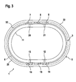
- Fig. 3 eine Ansicht der Unterseite des Adapterrings gemäß Fig. 1;
- Fig. 4 eine perspektivische Ansicht des in eine Dachpfanne eingesetzten Adapterrings;
- Fig. 5 einen Schnitt durch den in die Dachpfanne eingelassenen Adapterring gemäß Fig. 4 entlang B-B;
- Fig. 6 eine Explosionszeichnung des Dachdurchgangs mit dem Adapterring gemäß Fig. 4 sowie einem standardisierten Aufsatz.
- In Fig. 1 ist eine perspektivische Seitenansicht eines Adapterrings 1 für das Anbringen von standardisierten Aufsätzen an einer Dachpfanne dargestellt, wobei ein standardisierter Aufsatz nicht gezeigt ist.
- Der Adapterring 1 weist einen eine Durchführungsöffnung 2 umgebenden Durchführungskragen 3 auf, an dessen Außenseite 4 ein Außenring 5 angeordnet ist. An dem unter dem Außenring 5 angeordneten Abschnitt 6 des Durchführungskragens 3 sind mehrere Fixierelemente 7, 8, 9 angebracht. Der Durchführungskragen 3 kann im Querschnitt die Form einer Ellipse haben, aber auch kreisförmig oder n-eckig sein.
- In der Innenseite 10 des Durchführungskragens 3 ist ein Innenring 11 angeordnet, wobei unterhalb dieses Innenrings 11 mehrere Einrastelemente angebracht sind, von denen nur die Einrastelemente 12, 13 zu erkennen sind.
- Fig. 2 zeigt eine Frontansicht des Adapterrings 1 gemäß Fig. 1 mit Blick in Richtung A gemäß Fig. 1. Zu erkennen ist wiederum der Durchführungskragen 3 mit dem Außenring 5, der den Durchführungskragen 3 in einen oberen Abschnitt 15 und einen unteren Abschnitt 6 unterteilt.
- An den Seiten des unteren Abschnitts 6 weist der Adapterring 1 mehrere sich gegenüber liegende Fixierelemente 9, 14 auf. Diese Fixierelemente 9, 14 dienen dazu, den Adapterring 1 an einer hier nicht gezeigten Dachpfanne zu fixieren, wobei der Adapterring 1 in eine in die Dachpfanne eingelassene Einsatzöffnung eingebracht wird, so dass die Dachpfanne zumindest teilweise im Bereich 16, 17, d. h. zwischen den Fixierelementen 9, 14 und dem Außenring 5 angeordnet ist.
- Fig. 3 zeigt die Unterseite des in Fig. 1 dargestellten Adapterrings 1. Zu erkennen ist der am Durchführungskragen 3 angeordnete Innenring 11 sowie der Außenring 5. Oberhalb des Innenrings 11 sind am Durchführungskragen 3 vier Einrastelemente 12, 13, 20, 21 zu sehen. Diese Einrastelemente 12, 13, 20, 21 dienen dazu, mit eigens dafür vorgesehenen Gegenelementen an einem standardisierten Aufsatz eine feste Verbindung einzugehen. Ein Verrutschen des Aufsatzes, der hier nicht dargestellt ist, ist somit nicht mehr möglich.
- Diese Einrastelemente 12, 13, 20, 21 sind vorzugsweise symmetrisch am Durchführungskragen 3 angeordnet, wobei auch eine ungerade Anzahl an am Durchführungskragen 3 angeordneten Einrastelementen denkbar ist.
- Weiterhin sind die am unteren Abschnitt 6 des Durchführungskragens 3 angebrachten Fixierelemente 7 bis 9, 14, 18, 19 zu sehen, die vorzugsweise symmetrisch zueinander angeordnet sind.
- Die hier gezeigte Seite 22 des Außenrings 5 ist mit Klebstoff 32 versehen. Da der Adapterring 1 mit der Seite 22 des Außenrings 5 auf der Oberseite der Dachpfanne aufliegt, wird der Adapterring 1 nicht nur über die Fixierelemente 7 bis 9, 14, 18, 19, sondern auch mittels des Klebstoffs fest mit der Dachpfanne verbunden. Der Klebstoff bewirkt zudem eine wasserdichte Verbindung zwischen dem Adapterring 1 und der Dachpfanne.
- Dadurch dass der Adapterring 1 über die Fixierelemente 7 bis 9, 14, 18, 19 an der Dachpfanne befestigt ist, ist es nicht nötig, den Dachpfanne mit dem daran befestigten Adapterring 1 zwischenzulagern, damit der Klebstoff 32 aushärtet, sondern der Dachpfanne mit dem Adapterring 1 kann direkt zur Eindeckung des Dachs eingesetzt werden. Der Klebstoff 32 kann damit auch nach Einbau der Dachpfanne in das Dach aushärten.
- Die Fixierelemente 7 bis 9, 14, 18, 19 erfüllen damit zwei Funktionen. Zum einen stabilisieren sie den Adapterring 1 mit einem daran befestigten standardisierten Aufsatz, und zum andern entlasten sie den Klebstoff 32.
- In Fig. 4 ist eine perspektivische Ansicht des in eine Einsatzöffnung einer Dachpfanne 23 eingesetzten Adapterrings 1 gezeigt. Bevor der Adapterring 1 in die Dachpfanne 23 eingesetzt werden kann, wird zum Beispiel mit einem Hochdruckwasserstrahl eine Einsatzöffnung in die Dachpfanne 23 geschnitten. Diese Einsatzöffnung besitzt vorzugsweise eine Größe, die gewährleistet, dass der Adapterring 1 zum einen mit dem Außenring 5 zumindest teilweise auf der Dachpfanne 23 aufliegt und dass zum andern der Adapterring 1 über die Fixierelemente 7 bis 9, 14, 18, 19 in der Dachpfanne 23 fixiert ist.
- Vorzugsweise liegt der Adapterring 1 so auf, dass die gesamte Seite 22 des Außenrings 5 in großflächigem Kontakt mit dem Dachpfanne 23 steht.
- Wie in Fig. 4 zu sehen, weist der Adapterring 1 dafür eine Form auf, die an die Oberflächenkontur der Dachpfanne 23 angepasst ist, wodurch gewährleistet wird, dass der Außenring 5 an jeder Stelle mit dem Dachpfanne 23 in Kontakt steht.
- In Fig. 5 ist ein Schnitt B-B durch den in die Dachpfanne 23 eingelassenen Adapterring 1 gemäß Fig. 4 dargestellt. Zu sehen sind der Innenring 11 mit den darunter angeordneten Einrastelementen 13, 20, wobei die Einrastelemente 13, 20 sich gegenüberliegen.
- Der Durchführungskragen 3 weist, wie hier wiederum zu sehen ist, eine der Oberflächenkontur der Dachpfanne 23 angepasste Form auf. Die Dachpfanne, die hier nur ausschnittsweise dargestellt ist, ist zwischen dem Außenring 5 und den Fixierelementen eingeschlossen, wobei nur die Fixierelemente 8, 18 zu erkennen sind. Der Abstand zwischen der Seite 22 des Außenrings 5 und den Fixierelementen 8, 18 entspricht dabei etwa der Dicke der Dachpfanne 23.
- Zwischen dem auf der Oberseite der Dachpfanne 23 aufliegenden Außenring 5 und der Dachpfanne ist eine wasserdichte Klebeverbindung 23a dargestellt.
- Der Adapterring 1 besteht dabei aus einem Material, z. B. Kunststoff, das eine gewisse Flexibilität besitzt. Die Flexibilität soll im unteren Abschnitt 6 des Durchführungskragens 3 vorzugsweise so groß sein, dass die Fixierelemente 8, 18 dieses unteren Abschnitts 6 nicht abbrechen, wenn der Durchführungskragen 3 in die Einsatzöffnung der Dachpfanne 23 eingesetzt wird. Es muss somit gewährleistet sein, dass die Fixierelemente 8, 18 beim Einschieben des unteren Abschnitts 6 des Durchführungskragens 3 in Richtung der Durchführungsöffnung 2 gepresst werden können, um sich dann wieder nach außen zu bewegen, um so zusammen mit dem Außenring 5 den Dachpfanne 23 zu umschließen.
- In Fig. 6 ist eine Explosionsdarstellung eines Dachdurchgangs dargestellt, der aus einer Dachpfanne 23 und dem Adapterring 1 gemäß der Fig. 4 besteht und mit einem standardisierten Aufsatz 25 zusammenfügbar ist. Zu sehen sind die Dachpfanne 23 mit der eingeschnittenen Einsatzöffnung 24 sowie der Adapterring 1.
- Der Durchführungskragen 3 des Adapterrings 1 trägt im unteren Abschnitt 6 die Fixierelemente 7 bis 9, 14, 18, 19. Zu erkennen ist außerdem der Außenring 5, der an seiner Unterseite mit einem Kleber versehen und auf die Dachpfanne 23 aufgesetzt ist. Der untere Abschnitt 6 des Durchführungskragens 3 ist durch die Einsatzöffnung 24 geführt, sodass der Adapterring 1 mittels der Fixierelemente 7 bis 9, 14, 18, 19 an der Dachpfanne 23 befestigt ist.
- Man erkennt auch den Innenring 11 mit den darunter angeordneten Einrastelementen, wobei nur die Einrastelemente 20, 21 zu erkennen sind.
- Oberhalb des Adapterrings 1 ist der standardisierte Aufsatz 25 dargestellt, wobei es sich bei dem Aufsatz 25 um ein Lüftungselement handelt mit einer Haube 26 und einem durch die Durchführungsöffnung 2 des Durchführungskragens 3 hindurchführbaren Rohr 27.
- Für den standardisierten Aufsatz 25 ist es wichtig, dass er eine die Durchführungsöffnung 2 des Adapterrings 1 abdeckende Haube 26 und Gegenelemente 28, 29 für das Verrasten mit dem Adapterring 1 besitzt, die aus einem flexiblen Material, z. B. Kunststoff bestehen. Mittels dieser Gegenelemente 28, 29 kann der standardisierte Aufsatz 25 fest mit den am Adapterring 1 angeordneten Einrastelementen 12, 13, 20, 21 verbunden werden. Vorzugsweise besitzen die Gegenelemente 28, 29 ösenförmige Öffnungen 30, 31, in welche die Einrastelemente 12, 13, 20, 21 eingreifen können.
- Sollen die Dachpfanne 23, der Adapterring 1 und der standardisierte Aufsatz 25 zusammengefügt werden, so wird wie folgt vorgegangen.
- Zuerst wird in die Dachpfanne 23 eine Einsatzöffnung 24 geschnitten. Anschließend wird auf die Seite 22 des Außenringes 5 ein Klebstoff 32 aufgetragen und der Adapterring 1 wird anschließend mit dem unteren Abschnitt 6 des Durchführungskragens 3 in die Einsatzöffnung 24 eingeführt, bis der Außenring 5 mit seiner Seite 22 auf dem Dachpfanne 23 aufliegt, so dass eine großflächige und wasserdichte Klebeverbindung entsteht. Die Dachpfanne 23 wird dabei zwischen dem Außenring 5 und den Fixierelementen 7 bis 9, 14, 18, 19 positioniert.
- Schließlich wird der standardisierte Aufsatz 25 auf den Adapterring 1 aufgesetzt. Der Aufsatz 25 ist erst dann fest an dem Adapterring 1 angeordnet, wenn die Einrastelemente 12, 13, 20, 21 in die Gegenelemente 28, 29 eingegriffen haben.
Claims (14)
- Dachdurchgang mit einer eine Einsatzöffnung (24) aufweisenden Dachpfanne (23) und einem Adapterring (1) zum Anbringen von standardisierten Aufsätzen (25), wobei der Adapterring (1) einen zumindest teilweise in die Einsatzöffnung (24) einführbaren Durchführungskragen (3) aufweist, dadurch gekennzeichnet, dass der Durchführungskragen (3) mit einem an die Oberflächenkontur der Dachpfanne (23) angepassten Außenring (5) versehen ist und dass der Durchführungskragen (3) einen in die Einsatzöffnung (24) einführbaren unteren Abschnitt (6) aufweist, der mit Fixierelementen (7 - 9, 14, 18, 19) zur Positionierung des Adapterrings (1) an der Dachpfanne (23) versehen ist.
- Dachdurchgang nach Anspruch 1, dadurch gekennzeichnet, dass die Fixierelemente (7 - 9, 14, 18, 19) symmetrisch zu einander angeordnet sind.
- Dachdurchgang nach Anspruch 1, dadurch gekennzeichnet, dass die Fixierelemente (7 - 9, 14, 18, 19) unterhalb des Außenrings (5) angeordnet sind.
- Dachdurchgang nach einem der Ansprüche 1 bis 3, dadurch gekennzeichnet, dass die Fixierelemente (7 - 9, 14, 18, 19) an die Wandung der Einsatzöffnung (24) anlegbar sind und hierdurch eine Klemmverbindung herstellen.
- Dachdurchgang nach einem der Ansprüche 1 bis 3, dadurch gekennzeichnet, dass der untere Abschnitt (6) des Durchführungskragens (3) an der Unterseite der Dachpfanne (23) übersteht und die Fixierelemente (7 - 9, 14, 18, 19) an die Unterseite anlegbar sind und diese somit untergreifen.
- Dachdurchgang nach einem der Ansprüche 1 bis 5, dadurch gekennzeichnet, dass der Außenring (5) eine zumindest teilweise auf der Dachpfanne (23) aufliegende Seite (22) aufweist, die mit einem klebenden und dichtenden Verbindungsmittel (32) versehen ist.
- Dachdurchgang nach einem der Ansprüche 1 bis 6, dadurch gekennzeichnet, dass der Durchführungskragen (3) in Form einer Ellipse ausgebildet ist.
- Dachdurchgang nach einem der Ansprüche 1 bis 7, dadurch gekennzeichnet, dass der Durchführungskragen (3) mit Einrastelementen (12, 13; 20, 21) zum Fixieren der standardisierten Aufsätze (25) versehen ist.
- Dachdurchgang nach Anspruch 8, dadurch gekennzeichnet, dass die Einrastelemente (12, 13; 20, 21) einander gegenüber liegen.
- Dachdurchgang nach Anspruch 8 oder 9, dadurch gekennzeichnet, dass die Einrastelemente (12, 13; 20, 21) unterhalb eines am Durchführungskragen (3) befindlichen Innenrings (11) symmetrisch zu einander angeordnet sind.
- Dachdurchgang nach einem der Ansprüche 8 bis 10, dadurch gekennzeichnet, dass die Einrastelemente (12, 13, 20, 21) mit an den standardisierten Aufsätzen (25) angeordneten Gegenelementen (28, 29) zusammenwirken.
- Verfahren zur Herstellung eines Dachdurchgangs, gekennzeichnet durch folgende Schritte:a) eine Dachpfanne (23) wird mit einer Einsatzöffnung (24) versehen;b) auf einer Seite (22) eines Außenrings (5) eines Adapterrings (1) wird ein Verbindungsmittel (32) aufgebracht;c) der einen Durchführungskragen (3) aufweisende Adapterring (1) wird mit diesem Durchführungskragen (3) in die Einsatzöffnung (24) eingebracht;d) der mit Fixierelementen (7 - 9, 14, 18, 19) versehene Adapterring (1) wird mittels dieser Fixierelemente (7 - 9, 14, 18, 19) relativ zur Dachpfanne (23) positioniert;e) die mit dem Verbindungsmittel (32) versehene Seite (22) des Außenrings (5) wird an die Oberfläche der Dachpfanne (23) gedrückt.
- Verfahren nach Anspruch 12, dadurch gekennzeichnet, dass die Einsatzöffnung (24) mittels eines Hochdruckwasserstrahls in die Dachpfanne (23) geschnitten wird.
- Verfahren nach Anspruch 12, dadurch gekennzeichnet, dass nach der Herstellung des Dachdurchgangs ein standardisierter Aufsatz (25) aufgesetzt wird.
Applications Claiming Priority (1)
| Application Number | Priority Date | Filing Date | Title |
|---|---|---|---|
| DE102006003478A DE102006003478A1 (de) | 2006-01-25 | 2006-01-25 | Dachdurchgang und Verfahren zu seiner Herstellung |
Publications (3)
| Publication Number | Publication Date |
|---|---|
| EP1813737A2 true EP1813737A2 (de) | 2007-08-01 |
| EP1813737A3 EP1813737A3 (de) | 2009-12-30 |
| EP1813737B1 EP1813737B1 (de) | 2013-09-25 |
Family
ID=37963886
Family Applications (1)
| Application Number | Title | Priority Date | Filing Date |
|---|---|---|---|
| EP06126953.6A Active EP1813737B1 (de) | 2006-01-25 | 2006-12-21 | Dachdurchgang und Verfahren zu seiner Herstellung |
Country Status (3)
| Country | Link |
|---|---|
| US (1) | US20070220819A1 (de) |
| EP (1) | EP1813737B1 (de) |
| DE (1) | DE102006003478A1 (de) |
Cited By (2)
| Publication number | Priority date | Publication date | Assignee | Title |
|---|---|---|---|---|
| FR2927917A1 (fr) * | 2008-02-22 | 2009-08-28 | Monier Technical Ct Ltd | Tuile pour une sortie de toit |
| EP3358097A1 (de) * | 2017-02-07 | 2018-08-08 | Imerys TC | Dunstrohr für eine dacheindeckung eines gebäudes, das einen schutz der verklebung der haube umfasst |
Families Citing this family (7)
| Publication number | Priority date | Publication date | Assignee | Title |
|---|---|---|---|---|
| US7568314B2 (en) * | 2004-08-05 | 2009-08-04 | Pacc Systems I.P., Llc | Flashing kit for wall penetrations |
| DE102013100646A1 (de) | 2013-01-23 | 2014-07-24 | Monier Roofing Components Gmbh | Durchgangsdachpfanne |
| US10746421B2 (en) | 2015-11-13 | 2020-08-18 | Lomanco, Inc. | Vent |
| US9853595B1 (en) * | 2016-08-18 | 2017-12-26 | Yanegijutsukenkyujo Co., Ltd. | Fixture for on-roof installation object and fixing structure of on-roof installation object |
| USD874638S1 (en) | 2017-09-13 | 2020-02-04 | Lomanco, Inc. | Portion of a vent |
| USD873984S1 (en) | 2017-09-13 | 2020-01-28 | Lomanco, Inc. | Vent |
| US11946263B2 (en) * | 2020-12-28 | 2024-04-02 | Golden Rule Fasteners, Inc. | Roof vent with contoured foot |
Family Cites Families (21)
| Publication number | Priority date | Publication date | Assignee | Title |
|---|---|---|---|---|
| DE7411996U (de) * | 1974-07-18 | Braas & Co Gmbh | Dacheindeckungsplatte mit einem Aufsatz in Form eines Lüftungsrohres, eines Antennendurchganges o. dgl | |
| DE7412053U (de) * | 1974-07-11 | Braas & Co Gmbh | Dacheindeckungsplatte mit Lüfterelement | |
| DE1779171U (de) * | 1958-06-16 | 1958-12-11 | Helmhold Schneider | Dachabdichtungsplatte aus kunststoff fuer antennen und dachstaender. |
| JPS5922329B2 (ja) * | 1976-06-21 | 1984-05-25 | 株式会社ニフコ | コ−ド留め具 |
| US4383692A (en) * | 1981-06-02 | 1983-05-17 | Murray Corporation | Grommet seal |
| DE3914025A1 (de) * | 1989-04-28 | 1990-10-31 | Braas & Co Gmbh | Lueftungsvorrichtung |
| DE9004653U1 (de) * | 1990-04-25 | 1990-08-02 | Fleck, Oskar, 4354 Datteln | Dunstrohr-Entlüftungsvorrichtung |
| US5144777A (en) * | 1991-04-09 | 1992-09-08 | Allsteel Inc. | Grommet assembly for wall panels |
| FI88954C (fi) * | 1991-07-15 | 1993-07-26 | Sk Fastening Ltd Oy | Element foer roergenomfoering i tegeltak |
| US5326060A (en) * | 1992-06-25 | 1994-07-05 | Mid-America Building Products Corporation | Plastic building wall mount assembly |
| US5561952A (en) * | 1994-04-11 | 1996-10-08 | Tapco International Corporation | Combination skylight/static ventilator |
| US5791985A (en) * | 1995-06-06 | 1998-08-11 | Tapco International | Modular soffit vent |
| DE29510448U1 (de) * | 1995-06-28 | 1995-09-07 | J. Heuel und Söhne Aluminium-Gießerei GmbH, 59846 Sundern | Entlüftungsvorrichtung für ein Dach |
| DE19806712C1 (de) * | 1998-02-18 | 1999-10-07 | Nelskamp Dachziegelwerke Gmbh | Vorrichtung zur Führung eines Entlüftungskanals über Dach |
| DE20011710U1 (de) * | 2000-07-07 | 2000-09-14 | Fleck, Oskar, 45711 Datteln | Wrasenlüfter |
| EP1382769A3 (de) * | 2002-07-20 | 2004-03-17 | Tony Skuse | Vorrichtung zum Beleuchten eines Gebäudeinnenraumes |
| US7047857B2 (en) * | 2002-11-26 | 2006-05-23 | Intense Speed, Llc | Water jet cutting machine |
| US7114301B2 (en) * | 2004-03-08 | 2006-10-03 | Compagnie De Cheminees Industrielles, Inc. | Flashing for inclined roof and method for installing the same |
| DE202004009235U1 (de) * | 2004-06-14 | 2004-11-11 | Möltner, Friedrich A. | Entlüftungselement zur Verwendung an Gebäudedächern |
| US7721493B2 (en) * | 2005-04-18 | 2010-05-25 | Rubbermaid Incorporated | Roof panel assembly with skylight |
| US7610726B2 (en) * | 2005-05-05 | 2009-11-03 | Tapco International Corporation | Housing assembly |
-
2006
- 2006-01-25 DE DE102006003478A patent/DE102006003478A1/de not_active Withdrawn
- 2006-12-21 EP EP06126953.6A patent/EP1813737B1/de active Active
-
2007
- 2007-01-24 US US11/626,650 patent/US20070220819A1/en not_active Abandoned
Cited By (3)
| Publication number | Priority date | Publication date | Assignee | Title |
|---|---|---|---|---|
| FR2927917A1 (fr) * | 2008-02-22 | 2009-08-28 | Monier Technical Ct Ltd | Tuile pour une sortie de toit |
| EP3358097A1 (de) * | 2017-02-07 | 2018-08-08 | Imerys TC | Dunstrohr für eine dacheindeckung eines gebäudes, das einen schutz der verklebung der haube umfasst |
| FR3062663A1 (fr) * | 2017-02-07 | 2018-08-10 | Edilians | Tuile a douille pour une couverture de batiment comportant une protection du collage du bulbe |
Also Published As
| Publication number | Publication date |
|---|---|
| DE102006003478A1 (de) | 2007-08-02 |
| US20070220819A1 (en) | 2007-09-27 |
| EP1813737B1 (de) | 2013-09-25 |
| EP1813737A3 (de) | 2009-12-30 |
Similar Documents
| Publication | Publication Date | Title |
|---|---|---|
| DE2801902C2 (de) | Dichtungsanordnung zur Bildung einer wetterfesten Dichtung zwischen einem länglichen Bauteil und einer nicht ebenen Oberfläche | |
| EP2480732B1 (de) | Dachdurchgangspfanne | |
| EP1813737B1 (de) | Dachdurchgang und Verfahren zu seiner Herstellung | |
| DE9405203U1 (de) | Rollbarer Dichtungsstreifen für eine First- oder Gratabdeckung | |
| EP2492411B1 (de) | In ein mit Dachsteinen eingedecktes Dach einsetzbare Lüftungsvorrichtung | |
| AT15972U1 (de) | Installationsblock | |
| EP1826334A2 (de) | Notüberlauf | |
| EP2759652B1 (de) | Durchgangsdachpfanne | |
| DE29505860U1 (de) | Vorrichtung zur Abdichtung eines Wassereinlaufes | |
| EP1960616B1 (de) | Dachplatte mit traufenseitigem plastischen streifen | |
| DE9211551U1 (de) | Dachentlüfter | |
| DE102006053721B4 (de) | Industriell vorgefertigtes Gebäudeelement und Formvorrichtung zu dessen Herstellung | |
| DE3131820A1 (de) | Verfahren zur herstellung einer verbundplatte | |
| DE19913597C2 (de) | Verfahren zur Herstellung einer Schwimmbeckenüberlaufrinne und Bauelement für den Aufbau einer Schwimmbeckenüberlaufrinne | |
| DE2364271C3 (de) | Formkörper aus Kunststoff, insbesondere Aufsatzkranz für Lichtkuppel | |
| DE2942687A1 (de) | Abflusstopf | |
| DE10105499B4 (de) | Abflussgully für den Anschluss an die Dachhaut zur Abdeckung von Flachdächern und ähnlichen Gebäudeflächen | |
| DE4028958C1 (de) | ||
| DE9313128U1 (de) | Dachdurchführung | |
| EP2995729B1 (de) | Wasserablauf mit Schaumstoffblock | |
| EP1970498B1 (de) | Abschlussprofilanordnung für Balkone, Terassen und dergleichen mit Plattenbelägen | |
| DE20103721U1 (de) | Flachdachentlüfter | |
| WO2005012661A1 (de) | Oberflächenentwässerungseinrichtung | |
| DE102017112934A1 (de) | Dichtrinnenanordnung | |
| EP3401582A1 (de) | Dichtelement und brandschutzset mit dichtelement |
Legal Events
| Date | Code | Title | Description |
|---|---|---|---|
| PUAI | Public reference made under article 153(3) epc to a published international application that has entered the european phase |
Free format text: ORIGINAL CODE: 0009012 |
|
| AK | Designated contracting states |
Kind code of ref document: A2 Designated state(s): AT BE BG CH CY CZ DE DK EE ES FI FR GB GR HU IE IS IT LI LT LU LV MC NL PL PT RO SE SI SK TR |
|
| AX | Request for extension of the european patent |
Extension state: AL BA HR MK YU |
|
| RAP1 | Party data changed (applicant data changed or rights of an application transferred) |
Owner name: MONIER ROOFING COMPONENTS GMBH & CO. KG |
|
| RAP1 | Party data changed (applicant data changed or rights of an application transferred) |
Owner name: MONIER ROOFING COMPONENTS GMBH |
|
| PUAL | Search report despatched |
Free format text: ORIGINAL CODE: 0009013 |
|
| AK | Designated contracting states |
Kind code of ref document: A3 Designated state(s): AT BE BG CH CY CZ DE DK EE ES FI FR GB GR HU IE IS IT LI LT LU LV MC NL PL PT RO SE SI SK TR |
|
| AX | Request for extension of the european patent |
Extension state: AL BA HR MK RS |
|
| 17P | Request for examination filed |
Effective date: 20100218 |
|
| 17Q | First examination report despatched |
Effective date: 20100621 |
|
| AKX | Designation fees paid |
Designated state(s): AT BE BG CH CY CZ DE DK EE ES FI FR GB GR HU IE IS IT LI LT LU LV MC NL PL PT RO SE SI SK TR |
|
| APBK | Appeal reference recorded |
Free format text: ORIGINAL CODE: EPIDOSNREFNE |
|
| APBN | Date of receipt of notice of appeal recorded |
Free format text: ORIGINAL CODE: EPIDOSNNOA2E |
|
| APBR | Date of receipt of statement of grounds of appeal recorded |
Free format text: ORIGINAL CODE: EPIDOSNNOA3E |
|
| APAF | Appeal reference modified |
Free format text: ORIGINAL CODE: EPIDOSCREFNE |
|
| APBT | Appeal procedure closed |
Free format text: ORIGINAL CODE: EPIDOSNNOA9E |
|
| GRAP | Despatch of communication of intention to grant a patent |
Free format text: ORIGINAL CODE: EPIDOSNIGR1 |
|
| INTG | Intention to grant announced |
Effective date: 20130702 |
|
| GRAS | Grant fee paid |
Free format text: ORIGINAL CODE: EPIDOSNIGR3 |
|
| GRAA | (expected) grant |
Free format text: ORIGINAL CODE: 0009210 |
|
| AK | Designated contracting states |
Kind code of ref document: B1 Designated state(s): AT BE BG CH CY CZ DE DK EE ES FI FR GB GR HU IE IS IT LI LT LU LV MC NL PL PT RO SE SI SK TR |
|
| REG | Reference to a national code |
Ref country code: GB Ref legal event code: FG4D Free format text: NOT ENGLISH |
|
| REG | Reference to a national code |
Ref country code: CH Ref legal event code: EP |
|
| REG | Reference to a national code |
Ref country code: AT Ref legal event code: REF Ref document number: 633768 Country of ref document: AT Kind code of ref document: T Effective date: 20131015 |
|
| REG | Reference to a national code |
Ref country code: IE Ref legal event code: FG4D Free format text: LANGUAGE OF EP DOCUMENT: GERMAN |
|
| REG | Reference to a national code |
Ref country code: DE Ref legal event code: R096 Ref document number: 502006013231 Country of ref document: DE Effective date: 20131128 |
|
| REG | Reference to a national code |
Ref country code: NL Ref legal event code: T3 |
|
| PG25 | Lapsed in a contracting state [announced via postgrant information from national office to epo] |
Ref country code: LT Free format text: LAPSE BECAUSE OF FAILURE TO SUBMIT A TRANSLATION OF THE DESCRIPTION OR TO PAY THE FEE WITHIN THE PRESCRIBED TIME-LIMIT Effective date: 20130925 Ref country code: SE Free format text: LAPSE BECAUSE OF FAILURE TO SUBMIT A TRANSLATION OF THE DESCRIPTION OR TO PAY THE FEE WITHIN THE PRESCRIBED TIME-LIMIT Effective date: 20130925 |
|
| REG | Reference to a national code |
Ref country code: LT Ref legal event code: MG4D |
|
| PG25 | Lapsed in a contracting state [announced via postgrant information from national office to epo] |
Ref country code: SI Free format text: LAPSE BECAUSE OF FAILURE TO SUBMIT A TRANSLATION OF THE DESCRIPTION OR TO PAY THE FEE WITHIN THE PRESCRIBED TIME-LIMIT Effective date: 20130925 Ref country code: GR Free format text: LAPSE BECAUSE OF FAILURE TO SUBMIT A TRANSLATION OF THE DESCRIPTION OR TO PAY THE FEE WITHIN THE PRESCRIBED TIME-LIMIT Effective date: 20131226 Ref country code: LV Free format text: LAPSE BECAUSE OF FAILURE TO SUBMIT A TRANSLATION OF THE DESCRIPTION OR TO PAY THE FEE WITHIN THE PRESCRIBED TIME-LIMIT Effective date: 20130925 Ref country code: FI Free format text: LAPSE BECAUSE OF FAILURE TO SUBMIT A TRANSLATION OF THE DESCRIPTION OR TO PAY THE FEE WITHIN THE PRESCRIBED TIME-LIMIT Effective date: 20130925 |
|
| PG25 | Lapsed in a contracting state [announced via postgrant information from national office to epo] |
Ref country code: RO Free format text: LAPSE BECAUSE OF FAILURE TO SUBMIT A TRANSLATION OF THE DESCRIPTION OR TO PAY THE FEE WITHIN THE PRESCRIBED TIME-LIMIT Effective date: 20130925 Ref country code: IS Free format text: LAPSE BECAUSE OF FAILURE TO SUBMIT A TRANSLATION OF THE DESCRIPTION OR TO PAY THE FEE WITHIN THE PRESCRIBED TIME-LIMIT Effective date: 20140125 Ref country code: CZ Free format text: LAPSE BECAUSE OF FAILURE TO SUBMIT A TRANSLATION OF THE DESCRIPTION OR TO PAY THE FEE WITHIN THE PRESCRIBED TIME-LIMIT Effective date: 20130925 Ref country code: SK Free format text: LAPSE BECAUSE OF FAILURE TO SUBMIT A TRANSLATION OF THE DESCRIPTION OR TO PAY THE FEE WITHIN THE PRESCRIBED TIME-LIMIT Effective date: 20130925 Ref country code: EE Free format text: LAPSE BECAUSE OF FAILURE TO SUBMIT A TRANSLATION OF THE DESCRIPTION OR TO PAY THE FEE WITHIN THE PRESCRIBED TIME-LIMIT Effective date: 20130925 |
|
| PG25 | Lapsed in a contracting state [announced via postgrant information from national office to epo] |
Ref country code: CY Free format text: LAPSE BECAUSE OF FAILURE TO SUBMIT A TRANSLATION OF THE DESCRIPTION OR TO PAY THE FEE WITHIN THE PRESCRIBED TIME-LIMIT Effective date: 20130925 Ref country code: PL Free format text: LAPSE BECAUSE OF FAILURE TO SUBMIT A TRANSLATION OF THE DESCRIPTION OR TO PAY THE FEE WITHIN THE PRESCRIBED TIME-LIMIT Effective date: 20130925 Ref country code: ES Free format text: LAPSE BECAUSE OF FAILURE TO SUBMIT A TRANSLATION OF THE DESCRIPTION OR TO PAY THE FEE WITHIN THE PRESCRIBED TIME-LIMIT Effective date: 20130925 |
|
| REG | Reference to a national code |
Ref country code: DE Ref legal event code: R097 Ref document number: 502006013231 Country of ref document: DE |
|
| BERE | Be: lapsed |
Owner name: MONIER ROOFING COMPONENTS G.M.B.H. Effective date: 20131231 |
|
| PG25 | Lapsed in a contracting state [announced via postgrant information from national office to epo] |
Ref country code: PT Free format text: LAPSE BECAUSE OF FAILURE TO SUBMIT A TRANSLATION OF THE DESCRIPTION OR TO PAY THE FEE WITHIN THE PRESCRIBED TIME-LIMIT Effective date: 20140127 |
|
| REG | Reference to a national code |
Ref country code: CH Ref legal event code: PL |
|
| PLBE | No opposition filed within time limit |
Free format text: ORIGINAL CODE: 0009261 |
|
| STAA | Information on the status of an ep patent application or granted ep patent |
Free format text: STATUS: NO OPPOSITION FILED WITHIN TIME LIMIT |
|
| PG25 | Lapsed in a contracting state [announced via postgrant information from national office to epo] |
Ref country code: MC Free format text: LAPSE BECAUSE OF FAILURE TO SUBMIT A TRANSLATION OF THE DESCRIPTION OR TO PAY THE FEE WITHIN THE PRESCRIBED TIME-LIMIT Effective date: 20130925 Ref country code: LU Free format text: LAPSE BECAUSE OF FAILURE TO SUBMIT A TRANSLATION OF THE DESCRIPTION OR TO PAY THE FEE WITHIN THE PRESCRIBED TIME-LIMIT Effective date: 20131221 Ref country code: IT Free format text: LAPSE BECAUSE OF FAILURE TO SUBMIT A TRANSLATION OF THE DESCRIPTION OR TO PAY THE FEE WITHIN THE PRESCRIBED TIME-LIMIT Effective date: 20130925 |
|
| 26N | No opposition filed |
Effective date: 20140626 |
|
| REG | Reference to a national code |
Ref country code: IE Ref legal event code: MM4A |
|
| PG25 | Lapsed in a contracting state [announced via postgrant information from national office to epo] |
Ref country code: DK Free format text: LAPSE BECAUSE OF FAILURE TO SUBMIT A TRANSLATION OF THE DESCRIPTION OR TO PAY THE FEE WITHIN THE PRESCRIBED TIME-LIMIT Effective date: 20130925 |
|
| REG | Reference to a national code |
Ref country code: DE Ref legal event code: R097 Ref document number: 502006013231 Country of ref document: DE Effective date: 20140626 |
|
| PG25 | Lapsed in a contracting state [announced via postgrant information from national office to epo] |
Ref country code: IE Free format text: LAPSE BECAUSE OF NON-PAYMENT OF DUE FEES Effective date: 20131221 Ref country code: CH Free format text: LAPSE BECAUSE OF NON-PAYMENT OF DUE FEES Effective date: 20131231 Ref country code: LI Free format text: LAPSE BECAUSE OF NON-PAYMENT OF DUE FEES Effective date: 20131231 Ref country code: BE Free format text: LAPSE BECAUSE OF NON-PAYMENT OF DUE FEES Effective date: 20131231 |
|
| REG | Reference to a national code |
Ref country code: AT Ref legal event code: MM01 Ref document number: 633768 Country of ref document: AT Kind code of ref document: T Effective date: 20131221 |
|
| PG25 | Lapsed in a contracting state [announced via postgrant information from national office to epo] |
Ref country code: AT Free format text: LAPSE BECAUSE OF NON-PAYMENT OF DUE FEES Effective date: 20131221 |
|
| PG25 | Lapsed in a contracting state [announced via postgrant information from national office to epo] |
Ref country code: TR Free format text: LAPSE BECAUSE OF FAILURE TO SUBMIT A TRANSLATION OF THE DESCRIPTION OR TO PAY THE FEE WITHIN THE PRESCRIBED TIME-LIMIT Effective date: 20130925 |
|
| PG25 | Lapsed in a contracting state [announced via postgrant information from national office to epo] |
Ref country code: HU Free format text: LAPSE BECAUSE OF FAILURE TO SUBMIT A TRANSLATION OF THE DESCRIPTION OR TO PAY THE FEE WITHIN THE PRESCRIBED TIME-LIMIT; INVALID AB INITIO Effective date: 20061221 Ref country code: BG Free format text: LAPSE BECAUSE OF FAILURE TO SUBMIT A TRANSLATION OF THE DESCRIPTION OR TO PAY THE FEE WITHIN THE PRESCRIBED TIME-LIMIT Effective date: 20130925 |
|
| REG | Reference to a national code |
Ref country code: FR Ref legal event code: PLFP Year of fee payment: 10 |
|
| REG | Reference to a national code |
Ref country code: FR Ref legal event code: PLFP Year of fee payment: 11 |
|
| REG | Reference to a national code |
Ref country code: FR Ref legal event code: PLFP Year of fee payment: 12 |
|
| PGFP | Annual fee paid to national office [announced via postgrant information from national office to epo] |
Ref country code: GB Payment date: 20251218 Year of fee payment: 20 |
|
| PGFP | Annual fee paid to national office [announced via postgrant information from national office to epo] |
Ref country code: NL Payment date: 20251217 Year of fee payment: 20 Ref country code: FR Payment date: 20251217 Year of fee payment: 20 |
|
| PGFP | Annual fee paid to national office [announced via postgrant information from national office to epo] |
Ref country code: DE Payment date: 20251222 Year of fee payment: 20 |