EP3358097A1 - Dunstrohr für eine dacheindeckung eines gebäudes, das einen schutz der verklebung der haube umfasst - Google Patents
Dunstrohr für eine dacheindeckung eines gebäudes, das einen schutz der verklebung der haube umfasst Download PDFInfo
- Publication number
- EP3358097A1 EP3358097A1 EP18155386.8A EP18155386A EP3358097A1 EP 3358097 A1 EP3358097 A1 EP 3358097A1 EP 18155386 A EP18155386 A EP 18155386A EP 3358097 A1 EP3358097 A1 EP 3358097A1
- Authority
- EP
- European Patent Office
- Prior art keywords
- tile
- pierced
- bulb
- socket
- sleeve
- Prior art date
- Legal status (The legal status is an assumption and is not a legal conclusion. Google has not performed a legal analysis and makes no representation as to the accuracy of the status listed.)
- Granted
Links
Images
Classifications
-
- E—FIXED CONSTRUCTIONS
- E04—BUILDING
- E04D—ROOF COVERINGS; SKY-LIGHTS; GUTTERS; ROOF-WORKING TOOLS
- E04D1/00—Roof covering by making use of tiles, slates, shingles, or other small roofing elements
- E04D1/30—Special roof-covering elements, e.g. ridge tiles, gutter tiles, gable tiles, ventilation tiles
-
- E—FIXED CONSTRUCTIONS
- E04—BUILDING
- E04D—ROOF COVERINGS; SKY-LIGHTS; GUTTERS; ROOF-WORKING TOOLS
- E04D1/00—Roof covering by making use of tiles, slates, shingles, or other small roofing elements
- E04D1/29—Means for connecting or fastening adjacent roofing elements
- E04D1/2907—Means for connecting or fastening adjacent roofing elements by interfitted sections
- E04D1/2949—Means for connecting or fastening adjacent roofing elements by interfitted sections having joints with fluid-handling feature, e.g. a fluid channel for draining
-
- E—FIXED CONSTRUCTIONS
- E04—BUILDING
- E04D—ROOF COVERINGS; SKY-LIGHTS; GUTTERS; ROOF-WORKING TOOLS
- E04D1/00—Roof covering by making use of tiles, slates, shingles, or other small roofing elements
- E04D1/36—Devices for sealing the spaces or joints between roof-covering elements
-
- E—FIXED CONSTRUCTIONS
- E04—BUILDING
- E04D—ROOF COVERINGS; SKY-LIGHTS; GUTTERS; ROOF-WORKING TOOLS
- E04D1/00—Roof covering by making use of tiles, slates, shingles, or other small roofing elements
- E04D1/30—Special roof-covering elements, e.g. ridge tiles, gutter tiles, gable tiles, ventilation tiles
- E04D2001/307—Special roof-covering elements, e.g. ridge tiles, gutter tiles, gable tiles, ventilation tiles for passages in the roof surface
-
- E—FIXED CONSTRUCTIONS
- E04—BUILDING
- E04D—ROOF COVERINGS; SKY-LIGHTS; GUTTERS; ROOF-WORKING TOOLS
- E04D1/00—Roof covering by making use of tiles, slates, shingles, or other small roofing elements
- E04D1/30—Special roof-covering elements, e.g. ridge tiles, gutter tiles, gable tiles, ventilation tiles
- E04D2001/309—Ventilation tiles
-
- F—MECHANICAL ENGINEERING; LIGHTING; HEATING; WEAPONS; BLASTING
- F24—HEATING; RANGES; VENTILATING
- F24F—AIR-CONDITIONING; AIR-HUMIDIFICATION; VENTILATION; USE OF AIR CURRENTS FOR SCREENING
- F24F7/00—Ventilation
- F24F7/02—Roof ventilation
Definitions
- the present invention relates to a casing tile for a building cover, as well as to a method of manufacturing the casing tile, and a building cover comprising such casing tiles.
- Residential or professional buildings may have a tiled roof resting on a framework.
- the tiles are often made of terracotta, but also of concrete, or synthetic material such as a resin.
- the tiles meet different aesthetic criteria according to the regions. By their shapes, their colors and their sizes, the tiles help to form a style and an identity for the dwellings of a region.
- VMC controlled mechanical ventilation
- socket tile For air outlets it is known to use a specific tile, called socket tile, having a general shape and identical dimensions to fit like other standard tiles in a roof pan.
- the casing tile has in its center a substantially vertical circular contour, formed by a deformation of the surface upwards, which ends in a horizontal ring having in the center a circular passage.
- the horizontal ring receives a cap called lantern, having a globally cylindrical shape arranged vertically, comprising a closed top to prevent water ingress, and a vertical contour having a series of openings allowing the exit of the extracted air.
- a cap called lantern having a globally cylindrical shape arranged vertically, comprising a closed top to prevent water ingress, and a vertical contour having a series of openings allowing the exit of the extracted air.
- a type of known socket tile presented in particular by the document EP-A1-2759652 , has a generally flat shape similar to other standard tiles, having a central opening with a small rim of constant height on its contour. A plastic insert added to the opening is fixed by gluing or clipping on it.
- the small edge on the edge of the opening of this tile is easier to manufacture than a circular shape extending over the height, but still requires specific tools, and a maintenance in the stock of these particular tiles next all variants, which entails costs.
- socket tile presented in particular by the document DE-U1-29815502 , comprises a tile having a completely standard shape, in which an opening has been made for the passage of a vertical sleeve, designed to receive inside an exhaust air duct.
- the junction of the vertical sheath and the tile receives a bead of bonding around the entire circumference of this sheath, to ensure mechanical retention and sealing.
- this type of adhesive fastening disposed on the top of the socket tile has aging problems that can reduce the life of this tile.
- the ultraviolet radiation of the sun degrade in time the qualities of the glue, it may result in leakage of rainwater dripping on the tile that infiltrate through the degraded gluing, or a takeoff of the sheath.
- the present invention is intended to avoid these disadvantages of the prior art.
- a socket tile for a building cover intended to be arranged in the middle of standard tiles, this socket tile having a pierced tile, and a bulb prolonging the drilling of this pierced tile, this socket tile being remarkable in that the base of the bulb has a contour fitting in the piercing of the pierced tile, and comprises around this contour a continuous flange having an end which approaches the upper surface of this pierced tile, forming in below a channel receiving a bead of glue.
- This socket tile is that it can be cut in the middle of a standard tile to obtain the pierced tile, which allows the use of standard tiles kept in stock according to all their variants.
- the tile according to the invention may further comprise one or more of the following features, which may be combined with one another.
- the continuous flange comprises in a cross section a portion turned radially outwards, then a descending portion directed towards the top of the pierced tile.
- the channel below the continuous rim may have a generally rectangular cross section with a side that may be angled.
- the bulb comprises, above the continuous rim, a conical shape that becomes narrower, then a horizontal ring having a central bore.
- the bulb is formed in one piece by molding.
- the bulb may be formed by molding in a mold having an opening along a vertical axis.
- the cutting of the bore has a vertically disposed edge when the pierced tile is inclined according to the slope of the roof.
- the invention also relates to a method of manufacturing a socket tile comprising any one of the preceding features, comprising a step of cutting the central bore on a standard tile to form the pierced tile.
- the invention furthermore relates to a cover of a building comprising casing tiles comprising any one of the preceding features.
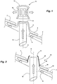
- the figure 1 has a cover with standard tiles 2 held on battens 4 of the frame to form rows of tiles, surrounding a socket tile 6 having in the center an elevation of the surface 8 of slightly conical shape tightening upwards, forming a circular contour around a vertical axis A.
- the surface elevation 8 ends with a horizontal ring 10 having a central bore receiving the air flow of a ventilation tube 18 which once installed arrives a little below this ring.
- a molded lantern 12 has a generally cylindrical shape, comprising at the bottom a flare provided to fit over the ring 10 of the socket tile 6. Above the flare, a straight cylindrical surface has a series of vertical slots 16, protected by a curved upper closure 14 protruding around this cylindrical surface to prevent rainwater entry into the slots.
- the sleeve tile 6 requires specific molds to make it, having the circular contour of the elevation of the surface 8. In particular, it is necessary to make moldings of these socket tiles 6 in all the variants of possible appearance included in the FIGS. Standard tiles 2, and maintain inventory to meet the demands of customers. These features represent a significant cost.
- the figure 2 has a sleeve tile 20 having a pierced tile 22 having a shape and appearance identical to those of the standard tiles 2, receiving on a central bore a bulb 24 having in the upper part the horizontal ring 10 receiving below the central bore the tube ventilation 18.
- the outline of the base of the bulb 24 has a continuous flange 26 fitted on the top of the pierced tile 22, containing inside a bead of continuous glue 28, which is glued on top of this pierced tile so as to ensure sealing and mechanical resistance on this complete contour.
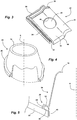
- the figure 3 presents the pierced tile 22 formed with the same mold as a standard tile 2, comprising an upper surface visible after the mounting of the cover, comprising by looking at the lower edge 40, on the left a flat part 30, and on the right a curved part 32 of reduced width relative to this flat part.
- the left edge of the pierced tile 22 has a longitudinal groove 34 terminating in a rim, receiving the right edge of the adjacent tile to form a rainwater flow channel.
- the upper edge of the pierced tile 22 has two parallel upper ribs 36, 38 defining between them a transverse groove which opens on the side in the longitudinal groove 34.
- the underside of the lower edge 40 has grooves 42 fitting on the upper ribs 36, 38 of the adjacent tile of the lower row.
- the pierced tile 22 has a circular central bore 44 formed largely on the flat portion 30, and projecting over the curved portion 32.
- the central bore 44 can be made by any cutting means adapted to the material of a standard tile 2, including machining with a cutting tool, stamping with a press tool, or other cutting methods such as laser cutting or water jet.
- the cutting of the central bore 44 can be performed to form an edge 46 of this cutout disposed vertically when the pierced tile 22 is inclined along the slope of the roof, which is generally between 20 and 45 °.
- the central bore 44 may be circular, or have any other shape, an oval shape in particular, depending on the contour of the bulb 24 to be adjusted inside.
- the Figures 4 and 5 present the bulb 24 which can be made of any material, in particular by molding a plastic material.
- the bulb 24 has at its base an outline 50 fitting into the bore 44 of the pierced tile 22, with a minimum clearance so as to position this bulb.
- the base of the contour 50 can form a vertical cylinder, fitting into the edge 46 of the central bore 44 which is also cut vertically when the pierced tile 22 is inclined in its mounting position.
- the continuous flange 26 surrounding the base of the contour 50 has a first portion turned radially outwardly 52, disposed generally in a plane parallel to the surface of the pierced tile 22, and a second descending portion 54 coming close to this tile which is perpendicular to the first part.
- the second descending portion 54 can join the surface of the tile 22 in a direction parallel to the axis of the contour 50.
- a continuous channel having a substantially rectangular section with a side which can be angled according to the position on the contour, arranged parallel to the surface of the pierced tile 22 is obtained.
- the continuous rim 26 follows the corrugations of the surface of the pierced tile 22, in particular the curved portion 32, so as to remain at a constant distance from this surface.
- the channel under the rim 26 has a generally constant section over the whole of its developed.
- the bulb 24 allows in particular a molding with a mold having an opening movement in the vertical direction, which comprises only two elements due to the absence of undercut of this bulb for demolding in this direction.
- the mold is simple to manufacture, and the production costs of the bulb 24 are reduced.
- the bulb 24 is turned over and a bead of continuous glue 28 is deposited in the channel under the rim 26. Then the bulb 24 is placed on the pierced tile 22 by easily centering it in the piercing 44, and is pressed so as to continuously glue the adhesive bead 28 on this tile. During this pressing operation the glue 28 remains in position thanks to the flange 26 surrounding it.
- the finished sleeve tile 20 is thus obtained in a simple, effective and rapid manner.
- the rim 26 covering the entire adhesive bead 28 protects this adhesive against mechanical aggressions, and in particular against exposures to ultraviolet rays.
- the pierced tile 22 having no thick rim around the bore 44, the bulb 24 stuck continuously around this piercing is an effective reinforcement of the tile to strengthen it in its central part which is more fragile.
- the bulb 24 may have relatively thin walls, with a thickness in particular between 1.5 and 3mm, the base of the contour 50 inserted in the bore 44 occupies a reduced radial distance which allows to provide a large diameter
- the thickness of the surface elevation made in the same material as the tile for a socket tile according to the prior art is generally between 8 and 12 mm.
Landscapes
- Engineering & Computer Science (AREA)
- Architecture (AREA)
- Civil Engineering (AREA)
- Structural Engineering (AREA)
- Non-Portable Lighting Devices Or Systems Thereof (AREA)
- Roof Covering Using Slabs Or Stiff Sheets (AREA)
Applications Claiming Priority (1)
| Application Number | Priority Date | Filing Date | Title |
|---|---|---|---|
| FR1750994A FR3062663B1 (fr) | 2017-02-07 | 2017-02-07 | Tuile a douille pour une couverture de batiment comportant une protection du collage du bulbe |
Publications (3)
| Publication Number | Publication Date |
|---|---|
| EP3358097A1 true EP3358097A1 (de) | 2018-08-08 |
| EP3358097C0 EP3358097C0 (de) | 2025-05-07 |
| EP3358097B1 EP3358097B1 (de) | 2025-05-07 |
Family
ID=58632464
Family Applications (1)
| Application Number | Title | Priority Date | Filing Date |
|---|---|---|---|
| EP18155386.8A Active EP3358097B1 (de) | 2017-02-07 | 2018-02-06 | Dunstrohr für eine dacheindeckung eines gebäudes, das einen schutz der verklebung der haube umfasst |
Country Status (3)
| Country | Link |
|---|---|
| EP (1) | EP3358097B1 (de) |
| ES (1) | ES3033290T3 (de) |
| FR (1) | FR3062663B1 (de) |
Cited By (1)
| Publication number | Priority date | Publication date | Assignee | Title |
|---|---|---|---|---|
| EP4733507A1 (de) * | 2024-10-28 | 2026-04-29 | Jean Nicolas Clément Ducrot | Verbindungssystem zwischen einem luftnetz und einem hülsenstein eines gebäudes und dachdurchführungsanordnung dafür |
Families Citing this family (1)
| Publication number | Priority date | Publication date | Assignee | Title |
|---|---|---|---|---|
| FR3129165B1 (fr) | 2021-11-15 | 2023-11-03 | Edilians | Dispositif d’étanchéité apte à être disposé sous une couche de tuiles d’une toiture |
Citations (6)
| Publication number | Priority date | Publication date | Assignee | Title |
|---|---|---|---|---|
| DE8710071U1 (de) * | 1987-07-23 | 1987-09-10 | Schnorr, Marin, 6729 Hatzenbühl | Überdach-Entlüftungsvorrichtung |
| NL8600633A (nl) * | 1986-03-11 | 1987-10-01 | Redland Bredero Bv | Ventilatiedakdoorvoer en ventilatiedakpan. |
| EP0984113A1 (de) * | 1998-08-29 | 2000-03-08 | HAUSprofi Bausysteme GmbH | Dachpfannenadapter |
| DE202004009235U1 (de) * | 2004-06-14 | 2004-11-11 | Möltner, Friedrich A. | Entlüftungselement zur Verwendung an Gebäudedächern |
| EP1813737A2 (de) * | 2006-01-25 | 2007-08-01 | Lafarge Roofing Components GmbH & Co. KG | Dachdurchgang und Verfahren zu seiner Herstellung |
| EP2759652A1 (de) * | 2013-01-23 | 2014-07-30 | Monier Roofing Components GmbH | Durchgangsdachpfanne |
Family Cites Families (1)
| Publication number | Priority date | Publication date | Assignee | Title |
|---|---|---|---|---|
| DE19628251C1 (de) * | 1996-07-12 | 1997-11-20 | Thomas Purr | Überdach-Entlüftungsvorrichtung |
-
2017
- 2017-02-07 FR FR1750994A patent/FR3062663B1/fr active Active
-
2018
- 2018-02-06 ES ES18155386T patent/ES3033290T3/es active Active
- 2018-02-06 EP EP18155386.8A patent/EP3358097B1/de active Active
Patent Citations (6)
| Publication number | Priority date | Publication date | Assignee | Title |
|---|---|---|---|---|
| NL8600633A (nl) * | 1986-03-11 | 1987-10-01 | Redland Bredero Bv | Ventilatiedakdoorvoer en ventilatiedakpan. |
| DE8710071U1 (de) * | 1987-07-23 | 1987-09-10 | Schnorr, Marin, 6729 Hatzenbühl | Überdach-Entlüftungsvorrichtung |
| EP0984113A1 (de) * | 1998-08-29 | 2000-03-08 | HAUSprofi Bausysteme GmbH | Dachpfannenadapter |
| DE202004009235U1 (de) * | 2004-06-14 | 2004-11-11 | Möltner, Friedrich A. | Entlüftungselement zur Verwendung an Gebäudedächern |
| EP1813737A2 (de) * | 2006-01-25 | 2007-08-01 | Lafarge Roofing Components GmbH & Co. KG | Dachdurchgang und Verfahren zu seiner Herstellung |
| EP2759652A1 (de) * | 2013-01-23 | 2014-07-30 | Monier Roofing Components GmbH | Durchgangsdachpfanne |
Cited By (1)
| Publication number | Priority date | Publication date | Assignee | Title |
|---|---|---|---|---|
| EP4733507A1 (de) * | 2024-10-28 | 2026-04-29 | Jean Nicolas Clément Ducrot | Verbindungssystem zwischen einem luftnetz und einem hülsenstein eines gebäudes und dachdurchführungsanordnung dafür |
Also Published As
| Publication number | Publication date |
|---|---|
| FR3062663B1 (fr) | 2022-03-18 |
| FR3062663A1 (fr) | 2018-08-10 |
| ES3033290T3 (en) | 2025-08-01 |
| EP3358097C0 (de) | 2025-05-07 |
| EP3358097B1 (de) | 2025-05-07 |
Similar Documents
| Publication | Publication Date | Title |
|---|---|---|
| CA2726084A1 (fr) | Dispositif de support de modules de recuperation d'energie solaire, unite de recuperation d'energie solaire et procede de montage de modules de recuperation d'energie solaire | |
| EP1710365B1 (de) | Abdichtungsvorrichtung für Gebäude und Verfahren zu ihrer Herstellung | |
| FR2562629A1 (fr) | Dispositif d'etancheite perfectionne | |
| EP3358097B1 (de) | Dunstrohr für eine dacheindeckung eines gebäudes, das einen schutz der verklebung der haube umfasst | |
| EP1275321A1 (de) | Kosmetischer Artikel und dessen Herstellungsverfahren | |
| EP2494120B1 (de) | Befestigungssystem für eine zwischenwand mit geführter klemmung | |
| FR2943577A1 (fr) | Procede de moulage d' une piece en matiere plastique avec une piece rapportee maintenue par aspiration, dispositif de moulage et utilisation | |
| EP3910127B1 (de) | Herstellungsverfahren einer abdichtungsvorrichtung für gebäude, die eine leitung und ein verbindungsorgan umfasst | |
| EP0994994B1 (de) | Paneele für eine schwimmbadwand | |
| EP2317028B1 (de) | Dachauslass für ein Rauchgasrohr | |
| EP4180731B1 (de) | Dichtungsvorrichtung, die unter einer dachpfannenschicht aufgebracht werden kann | |
| FR2875731A1 (fr) | Procede et dispositif de fabrication d'un boyau profile | |
| EP2045099B1 (de) | Fenster- oder Türflügel, der mindestens ein Dekorelement enthält | |
| EP0541437B1 (de) | Modulare Platte für horizontale Trennungen | |
| FR3032997A1 (fr) | Lame de decoration d’une menuiserie et son procede de fabrication | |
| FR2726796A1 (fr) | Receptacle etanche pour haut-parleur dans un vehicule | |
| FR2791714A1 (fr) | Procede de raccordement d'elements de caniveau extrude annele a double paroi et pieces de jonction | |
| EP2565341A2 (de) | Vorrichtung zur Integration und Befestigung eine Fotovoltaikpaneels auf einem Dach | |
| FR2654137A1 (fr) | Element de construction prefabrique pour le faite d'un mur et son assemblage. | |
| FR3072402B1 (fr) | Dispositif de raccordement d’une tuile a douille a une sortie d’air et ensemble d'evacuation d'air de toiture associe. | |
| EP4086405A1 (de) | Stützbasis, insbesondere für rauchabzugsanlage | |
| FR3137865A1 (fr) | Dispositif comportant un support translucide et des éléments comportant des caractéristiques de translucidité différentes de celles du support | |
| EP1410948A1 (de) | Dichtung für Beleuchtungseinheit | |
| EP2088255B1 (de) | Glasbaustein mit dekorativem Effekt | |
| FR2532237A1 (fr) | Procede et dispositif pour la fabrication par extrusion d'une tuile de rive |
Legal Events
| Date | Code | Title | Description |
|---|---|---|---|
| PUAI | Public reference made under article 153(3) epc to a published international application that has entered the european phase |
Free format text: ORIGINAL CODE: 0009012 |
|
| STAA | Information on the status of an ep patent application or granted ep patent |
Free format text: STATUS: THE APPLICATION HAS BEEN PUBLISHED |
|
| AK | Designated contracting states |
Kind code of ref document: A1 Designated state(s): AL AT BE BG CH CY CZ DE DK EE ES FI FR GB GR HR HU IE IS IT LI LT LU LV MC MK MT NL NO PL PT RO RS SE SI SK SM TR |
|
| AX | Request for extension of the european patent |
Extension state: BA ME |
|
| STAA | Information on the status of an ep patent application or granted ep patent |
Free format text: STATUS: REQUEST FOR EXAMINATION WAS MADE |
|
| 17P | Request for examination filed |
Effective date: 20181218 |
|
| RBV | Designated contracting states (corrected) |
Designated state(s): AL AT BE BG CH CY CZ DE DK EE ES FI FR GB GR HR HU IE IS IT LI LT LU LV MC MK MT NL NO PL PT RO RS SE SI SK SM TR |
|
| RAP1 | Party data changed (applicant data changed or rights of an application transferred) |
Owner name: EDILIANS |
|
| STAA | Information on the status of an ep patent application or granted ep patent |
Free format text: STATUS: EXAMINATION IS IN PROGRESS |
|
| 17Q | First examination report despatched |
Effective date: 20200617 |
|
| GRAP | Despatch of communication of intention to grant a patent |
Free format text: ORIGINAL CODE: EPIDOSNIGR1 |
|
| STAA | Information on the status of an ep patent application or granted ep patent |
Free format text: STATUS: GRANT OF PATENT IS INTENDED |
|
| INTG | Intention to grant announced |
Effective date: 20250109 |
|
| GRAS | Grant fee paid |
Free format text: ORIGINAL CODE: EPIDOSNIGR3 |
|
| GRAA | (expected) grant |
Free format text: ORIGINAL CODE: 0009210 |
|
| STAA | Information on the status of an ep patent application or granted ep patent |
Free format text: STATUS: THE PATENT HAS BEEN GRANTED |
|
| AK | Designated contracting states |
Kind code of ref document: B1 Designated state(s): AL AT BE BG CH CY CZ DE DK EE ES FI FR GB GR HR HU IE IS IT LI LT LU LV MC MK MT NL NO PL PT RO RS SE SI SK SM TR |
|
| REG | Reference to a national code |
Ref country code: GB Ref legal event code: FG4D Free format text: NOT ENGLISH |
|
| REG | Reference to a national code |
Ref country code: CH Ref legal event code: EP |
|
| REG | Reference to a national code |
Ref country code: DE Ref legal event code: R096 Ref document number: 602018081660 Country of ref document: DE |
|
| REG | Reference to a national code |
Ref country code: IE Ref legal event code: FG4D Free format text: LANGUAGE OF EP DOCUMENT: FRENCH |
|
| U01 | Request for unitary effect filed |
Effective date: 20250521 |
|
| U07 | Unitary effect registered |
Designated state(s): AT BE BG DE DK EE FI FR IT LT LU LV MT NL PT RO SE SI Effective date: 20250528 |
|
| REG | Reference to a national code |
Ref country code: ES Ref legal event code: FG2A Ref document number: 3033290 Country of ref document: ES Kind code of ref document: T3 Effective date: 20250801 |
|
| PG25 | Lapsed in a contracting state [announced via postgrant information from national office to epo] |
Ref country code: NO Free format text: LAPSE BECAUSE OF FAILURE TO SUBMIT A TRANSLATION OF THE DESCRIPTION OR TO PAY THE FEE WITHIN THE PRESCRIBED TIME-LIMIT Effective date: 20250807 Ref country code: GR Free format text: LAPSE BECAUSE OF FAILURE TO SUBMIT A TRANSLATION OF THE DESCRIPTION OR TO PAY THE FEE WITHIN THE PRESCRIBED TIME-LIMIT Effective date: 20250808 |
|
| PG25 | Lapsed in a contracting state [announced via postgrant information from national office to epo] |
Ref country code: PL Free format text: LAPSE BECAUSE OF FAILURE TO SUBMIT A TRANSLATION OF THE DESCRIPTION OR TO PAY THE FEE WITHIN THE PRESCRIBED TIME-LIMIT Effective date: 20250507 |
|
| PG25 | Lapsed in a contracting state [announced via postgrant information from national office to epo] |
Ref country code: HR Free format text: LAPSE BECAUSE OF FAILURE TO SUBMIT A TRANSLATION OF THE DESCRIPTION OR TO PAY THE FEE WITHIN THE PRESCRIBED TIME-LIMIT Effective date: 20250507 |
|
| PG25 | Lapsed in a contracting state [announced via postgrant information from national office to epo] |
Ref country code: RS Free format text: LAPSE BECAUSE OF FAILURE TO SUBMIT A TRANSLATION OF THE DESCRIPTION OR TO PAY THE FEE WITHIN THE PRESCRIBED TIME-LIMIT Effective date: 20250807 |
|
| PG25 | Lapsed in a contracting state [announced via postgrant information from national office to epo] |
Ref country code: IS Free format text: LAPSE BECAUSE OF FAILURE TO SUBMIT A TRANSLATION OF THE DESCRIPTION OR TO PAY THE FEE WITHIN THE PRESCRIBED TIME-LIMIT Effective date: 20250907 |
|
| PG25 | Lapsed in a contracting state [announced via postgrant information from national office to epo] |
Ref country code: SM Free format text: LAPSE BECAUSE OF FAILURE TO SUBMIT A TRANSLATION OF THE DESCRIPTION OR TO PAY THE FEE WITHIN THE PRESCRIBED TIME-LIMIT Effective date: 20250507 |
|
| PG25 | Lapsed in a contracting state [announced via postgrant information from national office to epo] |
Ref country code: CZ Free format text: LAPSE BECAUSE OF FAILURE TO SUBMIT A TRANSLATION OF THE DESCRIPTION OR TO PAY THE FEE WITHIN THE PRESCRIBED TIME-LIMIT Effective date: 20250507 |
|
| PG25 | Lapsed in a contracting state [announced via postgrant information from national office to epo] |
Ref country code: SK Free format text: LAPSE BECAUSE OF FAILURE TO SUBMIT A TRANSLATION OF THE DESCRIPTION OR TO PAY THE FEE WITHIN THE PRESCRIBED TIME-LIMIT Effective date: 20250507 |
|
| U20 | Renewal fee for the european patent with unitary effect paid |
Year of fee payment: 9 Effective date: 20260116 |
|
| PLBE | No opposition filed within time limit |
Free format text: ORIGINAL CODE: 0009261 |
|
| STAA | Information on the status of an ep patent application or granted ep patent |
Free format text: STATUS: NO OPPOSITION FILED WITHIN TIME LIMIT |
|
| REG | Reference to a national code |
Ref country code: CH Ref legal event code: L10 Free format text: ST27 STATUS EVENT CODE: U-0-0-L10-L00 (AS PROVIDED BY THE NATIONAL OFFICE) Effective date: 20260318 |
|
| 26N | No opposition filed |
Effective date: 20260210 |