EP1818111B1 - Dispositif et installation de suppression de poussière pour les matériaux granuleux - Google Patents
Dispositif et installation de suppression de poussière pour les matériaux granuleux Download PDFInfo
- Publication number
- EP1818111B1 EP1818111B1 EP07003046A EP07003046A EP1818111B1 EP 1818111 B1 EP1818111 B1 EP 1818111B1 EP 07003046 A EP07003046 A EP 07003046A EP 07003046 A EP07003046 A EP 07003046A EP 1818111 B1 EP1818111 B1 EP 1818111B1
- Authority
- EP
- European Patent Office
- Prior art keywords
- dust removing
- dust
- chamber
- granular material
- freed
- Prior art date
- Legal status (The legal status is an assumption and is not a legal conclusion. Google has not performed a legal analysis and makes no representation as to the accuracy of the status listed.)
- Not-in-force
Links
- 239000000428 dust Substances 0.000 title claims abstract description 139
- 239000008187 granular material Substances 0.000 title claims abstract description 70
- 238000005406 washing Methods 0.000 claims abstract description 40
- 238000007599 discharging Methods 0.000 claims abstract description 11
- 238000004891 communication Methods 0.000 claims abstract description 7
- 239000012530 fluid Substances 0.000 claims abstract description 7
- 239000000463 material Substances 0.000 claims description 18
- 238000006386 neutralization reaction Methods 0.000 claims description 8
- 238000001914 filtration Methods 0.000 claims description 5
- 238000005192 partition Methods 0.000 claims description 5
- 238000011144 upstream manufacturing Methods 0.000 claims description 5
- 230000005591 charge neutralization Effects 0.000 claims description 2
- 239000002245 particle Substances 0.000 description 16
- 239000004033 plastic Substances 0.000 description 13
- 229920003023 plastic Polymers 0.000 description 13
- 238000012545 processing Methods 0.000 description 6
- 239000003795 chemical substances by application Substances 0.000 description 5
- 230000001131 transforming effect Effects 0.000 description 5
- 238000002347 injection Methods 0.000 description 3
- 239000007924 injection Substances 0.000 description 3
- 239000000843 powder Substances 0.000 description 3
- 238000011109 contamination Methods 0.000 description 2
- 238000005202 decontamination Methods 0.000 description 2
- 230000003588 decontaminative effect Effects 0.000 description 2
- 230000005484 gravity Effects 0.000 description 2
- 150000002500 ions Chemical class 0.000 description 2
- 238000000034 method Methods 0.000 description 2
- 238000000926 separation method Methods 0.000 description 2
- 230000003068 static effect Effects 0.000 description 2
- 230000009466 transformation Effects 0.000 description 2
- 238000009825 accumulation Methods 0.000 description 1
- 230000008859 change Effects 0.000 description 1
- 239000003638 chemical reducing agent Substances 0.000 description 1
- 230000002860 competitive effect Effects 0.000 description 1
- 238000007791 dehumidification Methods 0.000 description 1
- 238000011143 downstream manufacturing Methods 0.000 description 1
- 238000005265 energy consumption Methods 0.000 description 1
- 238000007667 floating Methods 0.000 description 1
- 230000000670 limiting effect Effects 0.000 description 1
- 238000012423 maintenance Methods 0.000 description 1
- 238000007726 management method Methods 0.000 description 1
- 238000004519 manufacturing process Methods 0.000 description 1
- 238000002156 mixing Methods 0.000 description 1
- 239000000203 mixture Substances 0.000 description 1
- 238000012986 modification Methods 0.000 description 1
- 230000004048 modification Effects 0.000 description 1
- 238000000465 moulding Methods 0.000 description 1
- 230000003287 optical effect Effects 0.000 description 1
- 239000002861 polymer material Substances 0.000 description 1
- 230000008569 process Effects 0.000 description 1
- 230000001737 promoting effect Effects 0.000 description 1
- 239000002994 raw material Substances 0.000 description 1
- 230000009467 reduction Effects 0.000 description 1
- 230000002829 reductive effect Effects 0.000 description 1
- 229910001220 stainless steel Inorganic materials 0.000 description 1
- 239000010935 stainless steel Substances 0.000 description 1
- 230000003313 weakening effect Effects 0.000 description 1
Images
Classifications
-
- B—PERFORMING OPERATIONS; TRANSPORTING
- B07—SEPARATING SOLIDS FROM SOLIDS; SORTING
- B07B—SEPARATING SOLIDS FROM SOLIDS BY SIEVING, SCREENING, SIFTING OR BY USING GAS CURRENTS; SEPARATING BY OTHER DRY METHODS APPLICABLE TO BULK MATERIAL, e.g. LOOSE ARTICLES FIT TO BE HANDLED LIKE BULK MATERIAL
- B07B4/00—Separating solids from solids by subjecting their mixture to gas currents
- B07B4/02—Separating solids from solids by subjecting their mixture to gas currents while the mixtures fall
- B07B4/06—Separating solids from solids by subjecting their mixture to gas currents while the mixtures fall using revolving drums
-
- B—PERFORMING OPERATIONS; TRANSPORTING
- B07—SEPARATING SOLIDS FROM SOLIDS; SORTING
- B07B—SEPARATING SOLIDS FROM SOLIDS BY SIEVING, SCREENING, SIFTING OR BY USING GAS CURRENTS; SEPARATING BY OTHER DRY METHODS APPLICABLE TO BULK MATERIAL, e.g. LOOSE ARTICLES FIT TO BE HANDLED LIKE BULK MATERIAL
- B07B4/00—Separating solids from solids by subjecting their mixture to gas currents
- B07B4/08—Separating solids from solids by subjecting their mixture to gas currents while the mixtures are supported by sieves, screens, or like mechanical elements
Definitions
- the present invention relates to a device and a plant for removing contaminating agents, typically dust, from granular materials, particularly from granular plastics materials.
- the raw material In the field of the transformation processing of plastics materials, the raw material is usually in the form of granules, this being the most suitable shape for transport and storage in containers of different dimensions, e. g. silos and hoppers, as well as for any transformation processing at each processing step such as dehumidification and blending processes that precede moulding in an injection press.
- the granular plastics material is stored in sacks of about 25 liters in the case of relatively small amounts, or in sacks of about 1000 liters or in silos when dealing with large quantities.
- the granular material is subject to the risk of being contaminated by various foreign agents.
- the granular plastics material may be subject to substantial heat and mechanical stress, e. g. owing to friction while being pneumatically conveyed, which can result in particles in the form of dust granules being detached, which are added to the amount of dust already present in the mass of granular material.
- Dust particles thus formed are, so to speak, a "deteriorated" form of the polymer material, i. e. their chemical-physical properties, e. g. its softening temperature, its viscosity and the like, are often quite different from those of the plastics material from which they were originated.
- the presence of said dust particles in the final moulded product is undesirable, since it affects the technical characteristics thereof.
- dust removers Several systems for removing contaminating dust from granular materials, termed “dust removers” have been proposed in the past and are currently available on the market, which are usually installed upstream of a transforming machine.
- Said dust removers are a component of a dust removing plant and consist of one or more inclined grids onto which a granular material to be treated, i. e. from which any dust particles are to removed, is caused to fall by gravity. Due to impact against the grid or grids, any dust particles part from the granular material, and are then kept floating and moved away from the granular material by means of a flow rate of so called washing air blown through the grids. The washing-air flow rate, loaded with dust particles, is then filtered to be possibly recycled back into the dust removing plant, whereas the dust particles thus separated from the washing air are gathered in a suitable container.
- a dust remover according to the preamble of claim 1 is also known from document WO 2004/048006 , such a dust remover comprising fluidifying means for the granular material.
- an electric charge unloading apparatus is sometimes provided upstream of the dust removing plant, whose function is that of destroying or weakening any electrical binding force between dust particles and granules of plastics material.
- the granular plastics material to be decontaminated is caused to drop onto a plurality of grids, tipically two or three grids, and thus the air flow rate designed to float and drawing away any contamination dust particles flows through a plurality of static throttling elements, with consequent relevant losses of pressure. These dust removing plants then require a large input air flow rate with consequent higher energy consumption.
- the main object of the present invention is to provide a dust removing plant of a dynamic type which is suitable for fluidifying the granular material to be removed thereby assisting in promoting collisions between granules, and thus the separation form granules of any contaminating agents in the form of dust.
- Another object of the present invention is to provide a dust removing plant which includes a dosing system for dosing granular material to be decontaminated from dust in order to obtain a constant and controlled output flow rate of material free from dust.
- a further object of the present invention is to provide a dust removing plant including a plurality of dust removing devices, as well as a method of controlled supply of washing air to said devices.
- Not least object of the present invention is to provide a dust removing plant that can be manufactured at competitive costs, simple to install also in connection with pre-existing conveying and processing plants for plastics materials.
- a dust removing device for granular material which comprises:
- a dust removal plant which comprises:
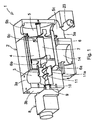
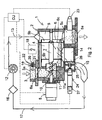
- a dust removing device generally indicated with reference numeral 1, includes an external shell or casing 2, in which three chambers are delimited, i. e. a supply or feed chamber 3 of granular material, an intermediate chamber 4 for dust removing or washing of granular material supplied from chamber 3, and a disposing chamber 5 for discharging granular material free from dust.
- the supply chamber 3 has an upper inlet opening 3a, typically in fluid communication, e. g. by falling, with a hopper (not shown in the drawings) storing granular material and communicates at a lower and lateral portion thereof with the intermediate decontamination chamber 4.
- the disposing chamber 5 is located downstream of the dust removing chamber 4, is in direct communication therewith, and has a lower output opening 5a for the granular material free of dust that is usually in fluid communication with a transforming machine (not shown in the drawings), e. g. an injection press of any suitable type.
- Fluidification means e. g. a sifter 6 having a foraminate lateral side, preferably cylindrical in shape and made of stainless steel sheet, are located in the intermediate dust removing chamber 4.
- the sifter 6 is designed to receive granular material to be decontaminated from the supply chamber 3 and to discharge it free of dust into the output chamber 5.
- the sifter 6, in use is mounted for rotation about a substantially horizontal axis and it can be set in rotation by a driving shaft 7 controlled by driving means of any suitable type, e. g. a ratio-motor 8 electrically connected with a programmable electronic control unit CU.
- the ratio-motor 8 is preferably arranged outside the casing 2, e. g. adjacent to the supply chamber 3 whose lateral side 3b has then a through hole 9 through which the driving shaft 7 extends, the hole 9 being sealed around the driving shaft 7 by suitable gasket means, e. g. a felt ring 10 to avoid leakages of granular material from the dust removing device 1.
- the driving shaft 7 extends through the three chambers 3, 4 and 5 and has one end thereof operatively connected and supported by the ratio-motor 8 outside the supply chamber 3, and its other end mounted for rotation in the casing 2 at the discharging chamber 5.
- the driving shaft supports, or is integral with, dosing and conveying means, e. g. a conveyor means like such as a motor-driven screw 11 surrounded by a respective work duct 11a which also extends between the supply chamber 3 and the dust removing chamber 4.
- dosing and conveying means e. g. a conveyor means like such as a motor-driven screw 11 surrounded by a respective work duct 11a which also extends between the supply chamber 3 and the dust removing chamber 4.
- Such screw 11 with its respective work duct 11 a constitutes a volumetric-type dosing and conveying system arranged for metering and conveying the granular material between the two chambers 3 and 4. Its dimensions are such that, for each rotation of the driving shaft 7, and thus of the screw 11, a predetermined amount of granular material is conveyed from the supply chamber 3 to the chamber 4, or more precisely to the sifter 6 located therein.
- the sifter 6 has a partition wall 6a next to the supply chamber 3, through which an end section of the working duct 11 a of screw 11 sealingly extends, and can be advantageously secured to the driving shaft 7 by means of two cross-shaped portions 6b and 6c arranged to support the shaft 7 and drag it in rotation, so that the shifter is rigid in rotation with the driving shaft 7. More particularly, a collecting zone for the granular material supplied and metered by the screw 11 is delimited between the partition wall 6a and the support portion 6b.
- Granules move from the collecting or gathering zone to dust removing zone between the two support portions 6b and 6c, where due to the sifter 6 being rotated, the granular material is fluidified, wich results in an increase of the collisions among the granules and detachment of any contaminating dust agents. Finally, the dust granular material free of dust moves over the support part 6c into the disposing or unloading chamber 5, from where it is fed to a downstream transforming machine.
- casing 2 has an input opening 5b through which washing air is supplied by way a washing air conveying duct 13 from a pressurized washing air source, e. g. a blower 12 electrically connected to the programmable control unit CU.
- a pressurized washing air source e. g. a blower 12 electrically connected to the programmable control unit CU.
- the air entering the dust removing device 1 via the opening 5b flows through the granular material while being fluidified in the sifter 6, captures any contaminating dust particles thereon, and flows then through the foraminate wall of the sifter 6 into a discharge piping 14 in fluid communication with a suction pipe 15.
- the air inlet opening 5b is located downstream of the intermediate dust removing chamber 4 and the air discharge piping 14 is located substantially upstream of the dust removing chamber 4, so that the washing air is supplied in countercurrent with respect to the granular material to be decontaminated.
- the washing air loaded with powder particles is filtered by means of a filter 16 of any suitable kind which is located on a washing air return duct 17, and recycled in the dust removing device.
- the dust removing device 1, at the inlet opening 3a of the granular material supply chamber 3, comprises an electrostatic-charge neutralization unit 18 designed to neutralize any electrostatic binding charge between granules and powder particles carried by them.
- a neutralization unit 18 comprises a high voltage generator 19, typically a generator of 4-7 kV alternating voltage, which is electrically connected to the control unit CU and supplies one or more ionizing points 20 located inside a sleeve 21. Compressed air is blown through a duct 22, and while flowing close to the ionizing point or points 20 becomes ionised and then meets the granular material entering the dust removing device 1 through opening 3a. Positive ions of the ionized air neutralize positive charges, whereas negative ions neutralize positive charges of inlet granular material.
- the electrostatic-charge neutralization unit 18 can be located at the washing air inlet opening 5b for the chamber 5. In such a case, the washing air entering the sifter 6 will be directly ionised with no need for further compressed air being supplied to the dust removing device 1, and neutralization of the electrostatic charge on the granules, with consequent separation of the dust particles from the granules, will take place inside the sifter 6.
- the granular material now free from contaminating dust particles flows into the disposing chamber 5, and then falls, by gravity, onto an end portion 5c of the disposing chamber from where it is fed to a downstream processing machine.
- a capacitive sensor 23 which is electrically connected to the programmable electronic control unit CU.
- the capacitive sensor 23 applies a signal to the control unit CU which, in turn, energizes the dust removing device 1, more particularly the ratio-reducer 8, the blower 12 and the electrostatic charge neutralization unit 18, in order to re-establish the level of dust free material in the end portion 5c.
- the dust removing device 1 comprises a return valve 24 which is located between the discharge duct 14 and the washing air suction duct 15.
- a return valve 24 comprises a valve body 25, inside which a shutter member 26 can move, the shutter member being controlled by a driving means of any suitably type, preferably a pneumatic driving means, e. g. a piston and cylinder unit 27 controlled by the control unit CU and designed to open/close a passage between the discharge duct 14 and the suction air duct 15.
- a dust removing plant in a plant for processing granular plastics material a plurality of dust removing devices are provided.
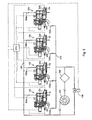
- a dust removing plant according to the embodiment shown in Figure 3 comprises four dust removing devices 101, 102, 103, 104, which are connected in parallel by means of inlet shunts 101a, 102a, 103a, 104a and outlet shunts 101b, 102b, 103b, 104b for pressurized washing air, and located between a common delivery duct 130, designed to deliver washing air supplied by a blower 120, and a common return duct 170 for the washing air which is intercepted by a filter 160.
- the dust removing plant comprises one blower 120 only and only one filter 160 to reduce both the overall dimensions and the management and maintenance costs.
- operation of the four dust removing devices 101, 102, 103 and 104 and the blower 120 is controlled by the common programmable electronic control unit CCU.
- the control unit CCU senses the working/inoperative condition of the four devices 101, 102, 103, 104 by checking the filling condition of the disposing chamber 51, 52, 53, 54 of each device, such filling condition being sensed by a respective level sensor 231, 232, 233, 234, then it controls the supply of pressurized washing air to the working devices 101 and 102, respectively, and the corresponding opening of return valves 243, 244.
- the CCU also controls the closure of the return valves 243, 244 of the inoperative dust removing devices 103 and 104, respectively.
- control unit CCU senses the change of state of the dust removing device 103 and waits until one of the working devices, e. g. the device 102, switches from its operative to its inoperative state. At this point, the control unit CCU causes the return valve 242 of the device 102 (which is now inoperative) to close, and causes the return valve 243 of the device 103 (which now is in its operative state) simultaneously to open.
- any air generated delivered by the blower 120 is supplied to such dust removing device.
- This condition is undesirable as such an excessive air flow would interfere with the granular material flow throughout the dust removing device and the fluidification inside the sifter 6.
- a bypass valve 150 is provided in the delivery duct 130, the valve 150 being electrically connected to the control unit CCU and designed to deviate the flow of air in excess supplied by the blower 120.
Landscapes
- Engineering & Computer Science (AREA)
- Mechanical Engineering (AREA)
- Cleaning In General (AREA)
- Combined Means For Separation Of Solids (AREA)
- Air Transport Of Granular Materials (AREA)
- Cyclones (AREA)
- Apparatuses For Bulk Treatment Of Fruits And Vegetables And Apparatuses For Preparing Feeds (AREA)
- Fertilizers (AREA)
Claims (20)
- Dispositif de suppression de poussière pour du matériau granuleux, comprenant :- un carter (2), délimitant une chambre d'alimentation (3) agencée pour fournir du matériau granuleux devant être débarrassé de la poussière, et formé avec une ouverture d'entrée (3a) ; une chambre d'extraction de poussière (4), conçue pour extraire la poussière du matériau granuleux et en communication fluidique avec ladite chambre d'alimentation (3) ; une chambre d'évacuation (5), pour du matériau granuleux débarrassé de la poussière, munie d'une ouverture d'évacuation (5a), de manière à permettre un écoulement ininterrompu de matériau granuleux, devant être débarrassé de la poussière, entre ladite chambre d'alimentation (3) et ladite chambre d'évacuation (5) ; une ouverture d'alimentation en air comprimé de lavage (5b) ; et un conduit de décharge d'air de lavage (14) ;- une source (12) d'air comprimé ;- un conduit de distribution (13), entre ladite source (12) d'air comprimé et ladite ouverture d'alimentation en air comprimé (5b):caractérisé en ce qu'il comprendune tuyauterie de retour (17), entre ledit conduit de décharge d'air de lavage (14) et ladite source (12) d'air de lavage ; etdes moyens de filtrage (16) dans ladite tuyauterie de retour,des moyens de fluidification (6) pour ledit matériau granuleux à débarrasser de la poussière, disposés dans ladite chambre d'évacuation des poussières (5),- des moyens de transport et de dosage (11, 11a), conçus pour transporter et doser ledit matériau granuleux devant être débarrassé de la poussière, et disposés entre ladite chambre d'alimentation (3) et ladite chambre d'évacuation des poussières (5).
- Dispositif selon la revendication 1, caractérisé en ce que lesdits moyens de fluidification comprennent un organe de tamisage (6), monté à rotation dans ladite chambre d'extraction de poussière (4), et des moyens d'entraînement (8) pour ledit organe de tamisage (6).
- Dispositif selon la revendication 2, caractérisé en ce que ledit organe de tamisage (6) comprend une paroi de séparation (6a), agencée en amont dudit écoulement ininterrompu, à proximité de ladite chambre d'alimentation (3), et au moins une partie de support (6b, 6c) pour l'entraîner en rotation.
- Dispositif selon la revendication 2 ou 3, caractérisé en ce que lesdits moyens d'entraînement comprennent une unité à motoréducteur (8).
- Dispositif selon l'une quelconque des revendications précédentes, caractérisé en ce lesdits moyens de transport et de dosage comprennent au moins un moyen convoyeur.
- Dispositif selon la revendication 5, caractérisé en ce que ledit au moins un moyen convoyeur comprend une vis (11) entrainée par moteur et un conduit de travail (11a) respectif.
- Dispositif selon la revendication 6, dépendant de la revendication 3, caractérisé en ce que ledit conduit de travail (11a) du au moins un moyen convoyeur s'étend à travers ladite paroi de séparation (6a), dans ladite chambre d'extraction de poussière (7) et est fermé de manière étanche par rapport à ladite paroi de séparation.
- Dispositif selon la revendication 6 ou 7, caractérisé en ce que lesdits au moins un moyen de transport à vis (11, 11a) sont en rotation solidaires avec ladite unité de tamisage (6).
- Dispositif selon l'une quelconque des revendications précédentes, caractérisé en ce que ladite ouverture d'entrée d'air (5b) est située en aval de ladite chambre d'extraction de poussière (4), et ledit conduit de décharge (14) est disposé sensiblement en amont de ladite chambre d'extraction de poussière (4), de manière que de l'air de lavage soit fourni à contre-courant par rapport au matériau granuleux à débarrasser de la poussière dans ladite chambre d'extraction de poussière (4).
- Dispositif selon l'une quelconque des revendications précédentes, caractérisé en ce qu'il comprend une unité de commande électronique (CU) programmable.
- Dispositif selon l'une quelconque des revendications précédentes, caractérisé en ce qu'il comprend une unité de neutralisation de charge électrostatique (18), commandée par ladite unité de commande électronique (CU) programmable.
- Dispositif selon la revendication 11, caractérisé en ce que ladite unité de neutralisation de charge électrostatique (18) comprend un générateur haute tension (19) incluant au moins un point d'ionisation (20).
- Dispositif selon la revendication 11 ou 12, caractérisé en ce que ladite unité de neutralisation de charge électrostatique (18) est située à ladite ouverture d'entrée (3a) de ladite chambre d'alimentation (3).
- Dispositif selon la revendication 11 ou 12, caractérisé en ce que ladite unité de neutralisation de charge électrostatique (18) est située à ladite ouverture d'alimentation en air comprimé de lavage (5a).
- Dispositif selon l'une quelconque des revendications précédentes, caractérisé en ce qu'il comprend des moyens de détection de niveau (23), disposés au niveau de ladite chambre d'évacuation (5) et conçus pour appliquer un signal de commande à ladite unité de commande électronique (CU) programmable.
- Dispositif selon la revendication 15, caractérisé en ce que lesdits moyens de détection de niveau (23) comprennent un capteur capacitif (23).
- Dispositif selon l'une quelconque des revendications précédentes, caractérisé en ce qu'il comprend des moyens de soupape (24), conçus pour commander l'écoulement d'air à travers ledit conduit de décharge (14) et susceptibles d'être commandés par ladite unité de commande électronique (CU) programmable.
- Dispositif selon la revendication 17, caractérisé en ce que lesdits moyens de soupape (24) comprennent un corps de soupape (25), un organe obturateur (26), et des moyens actionnés par un fluide (27), conçus pour commander ledit organe obturateur (26).
- Installation de suppression de poussière, caractérisée en ce qu'elle comprend :une pluralité de dispositifs de suppression de poussière (101, 102, 103, 104) selon l'une quelconque des revendications 1 à 17, ladite pluralité de dispositifs de suppression de poussière (101, 102, 103, 104) étant connectés entre eux en parallèle ;- au moins une source (120) d'air comprimé de lavage ;- une tuyauterie de distribution d'air comprimé de lavage (130) commune, s'étendant de ladite au moins une source (120) à chaque dispositif de suppression de poussière (101, 102, 103, 104) ;- une tuyauterie de retour d'air de lavage (170) commune, s'étendant de chaque dispositif de suppression de poussière (101, 102, 103, 104) à ladite au moins une source (120) ;- au moins un moyen de filtrage (160) dans ladite tuyauterie de retour (170) commune,lesdits dispositifs de suppression de poussière de ladite pluralité de dispositifs de suppression de poussière (101, 102, 103, 104) étant connectés en parallèle entre ladite tuyauterie de distribution (130) commune et ladite tuyauterie de retour (170) commune ; et
une unité de commande électronique (CCU) programmable commune, conçue pour commander ladite au moins une source d'air comprimé (120) et chacune desdits dispositifs de suppression de poussière (101, 102, 103, 104). - Installation selon la revendication 19, caractérisée en ce que elle comprend une valve de dérivation (150) susceptible d'être commandée par ladite unité de commande électronique (CCU) programmable commune et conçue pour dériver un éventuel écoulement d'air en excès fourni par ladite au moins une source (120) d'air comprimé de lavage.
Applications Claiming Priority (1)
| Application Number | Priority Date | Filing Date | Title |
|---|---|---|---|
| IT000033A ITVR20060033A1 (it) | 2006-02-14 | 2006-02-14 | Dispositivo ed impianto per la rimozione di polvere da materiali granulari |
Publications (3)
| Publication Number | Publication Date |
|---|---|
| EP1818111A2 EP1818111A2 (fr) | 2007-08-15 |
| EP1818111A3 EP1818111A3 (fr) | 2007-10-10 |
| EP1818111B1 true EP1818111B1 (fr) | 2010-05-05 |
Family
ID=38068891
Family Applications (1)
| Application Number | Title | Priority Date | Filing Date |
|---|---|---|---|
| EP07003046A Not-in-force EP1818111B1 (fr) | 2006-02-14 | 2007-02-13 | Dispositif et installation de suppression de poussière pour les matériaux granuleux |
Country Status (5)
| Country | Link |
|---|---|
| EP (1) | EP1818111B1 (fr) |
| AT (1) | ATE466670T1 (fr) |
| DE (1) | DE602007006244D1 (fr) |
| ES (1) | ES2345674T3 (fr) |
| IT (1) | ITVR20060033A1 (fr) |
Cited By (3)
| Publication number | Priority date | Publication date | Assignee | Title |
|---|---|---|---|---|
| KR20170084154A (ko) * | 2014-11-07 | 2017-07-19 | 알이씨 실리콘 인코포레이티드 | 실리콘 분말을 관리하기 위한 장치 및 방법 |
| WO2023083991A1 (fr) * | 2021-11-15 | 2023-05-19 | Compagnie Generale Des Etablissements Michelin | Procédé de séparation des composants d'un mélange de fibres et de granules par neutralisation électrostatique et tamisage, et installation correspondante |
| WO2025160403A1 (fr) * | 2024-01-24 | 2025-07-31 | Mannkind Corporation | Système de transport de poudre |
Families Citing this family (11)
| Publication number | Priority date | Publication date | Assignee | Title |
|---|---|---|---|---|
| DE102012108907B4 (de) * | 2012-09-21 | 2017-03-09 | Klaus Wilhelm | Verfahren und Vorrichtung zum Entstauben von Schüttgütern mittels Ionisierung |
| EP2730591A1 (fr) * | 2012-11-07 | 2014-05-14 | Kuraray Europe GmbH | Procédé de fabrication de polyvinylacétal avec une viscosité sélectionnée |
| DE102014113280B4 (de) * | 2014-09-15 | 2018-12-27 | HELIOS Gerätebau für Kunststofftechnik GmbH | Vorrichtung und Verfahren zum chargenweisen Entfernen von Staub aus einem Granulat |
| US10287171B2 (en) | 2016-05-05 | 2019-05-14 | Rec Silicon Inc | Tumbling device for the separation of granular polysilicon and polysilicon powder |
| US9682404B1 (en) | 2016-05-05 | 2017-06-20 | Rec Silicon Inc | Method and apparatus for separating fine particulate material from a mixture of coarse particulate material and fine particulate material |
| CN105772219B (zh) * | 2016-05-10 | 2017-10-24 | 中南大学 | 风力干式磁分选机 |
| DE102016119827B4 (de) * | 2016-10-18 | 2020-01-23 | Klaus Wilhelm | Verfahren und Vorrichtung zum Entstauben von Schüttgütern, insbesondere mittels Ionisierung |
| WO2019201723A1 (fr) * | 2018-04-20 | 2019-10-24 | Borealis Ag | Procédé d'élimination de poussière de particules de polymère dans un système de transport de polymère |
| US12048921B2 (en) | 2018-04-20 | 2024-07-30 | Borealis Ag | Method for transporting polyolefin particles in a polymer conveying system |
| CN108772296A (zh) * | 2018-07-03 | 2018-11-09 | 福建华宏天城机电设备有限公司 | 一种化工材料除尘筛选装置 |
| CN109663447B (zh) * | 2019-02-21 | 2024-03-08 | 唐山神州机械集团有限公司 | 一种井下基于循环气流的干选系统及干选方法 |
Family Cites Families (4)
| Publication number | Priority date | Publication date | Assignee | Title |
|---|---|---|---|---|
| FR1590114A (fr) * | 1968-04-12 | 1970-04-13 | ||
| JP2889075B2 (ja) * | 1993-03-23 | 1999-05-10 | 帝人化成株式会社 | 合成樹脂粒体に同伴する微粉体の除去装置及び貯留基地 |
| DE10054418B4 (de) * | 2000-11-03 | 2006-05-18 | Iss Engineering | Verfahren und Vorrichtung zur Entfernung von staubförmigen und faserigen Beimengungen aus Schüttgut |
| WO2004048006A1 (fr) * | 2002-11-28 | 2004-06-10 | Mbengineering Gmbh & Co. Kg | Procede et dispositif pour separer des particules de poussiere d'un granulat |
-
2006
- 2006-02-14 IT IT000033A patent/ITVR20060033A1/it unknown
-
2007
- 2007-02-13 AT AT07003046T patent/ATE466670T1/de not_active IP Right Cessation
- 2007-02-13 EP EP07003046A patent/EP1818111B1/fr not_active Not-in-force
- 2007-02-13 DE DE602007006244T patent/DE602007006244D1/de active Active
- 2007-02-13 ES ES07003046T patent/ES2345674T3/es active Active
Cited By (4)
| Publication number | Priority date | Publication date | Assignee | Title |
|---|---|---|---|---|
| KR20170084154A (ko) * | 2014-11-07 | 2017-07-19 | 알이씨 실리콘 인코포레이티드 | 실리콘 분말을 관리하기 위한 장치 및 방법 |
| WO2023083991A1 (fr) * | 2021-11-15 | 2023-05-19 | Compagnie Generale Des Etablissements Michelin | Procédé de séparation des composants d'un mélange de fibres et de granules par neutralisation électrostatique et tamisage, et installation correspondante |
| FR3129095A1 (fr) * | 2021-11-15 | 2023-05-19 | Compagnie Generale Des Etablissements Michelin | Procédé de séparation des composants d’un mélange de fibres et de granules par neutralisation électrostatique et tamisage, et installation correspondante |
| WO2025160403A1 (fr) * | 2024-01-24 | 2025-07-31 | Mannkind Corporation | Système de transport de poudre |
Also Published As
| Publication number | Publication date |
|---|---|
| EP1818111A2 (fr) | 2007-08-15 |
| ATE466670T1 (de) | 2010-05-15 |
| EP1818111A3 (fr) | 2007-10-10 |
| ES2345674T3 (es) | 2010-09-29 |
| DE602007006244D1 (de) | 2010-06-17 |
| ITVR20060033A1 (it) | 2007-08-15 |
Similar Documents
| Publication | Publication Date | Title |
|---|---|---|
| EP1818111A2 (fr) | Dispositif et installation de suppression de poussière pour les matériaux granuleux | |
| EP2412652B1 (fr) | Système de transport pneumatique pour matériaux particulaires | |
| EP0257683B1 (fr) | Appareil de distribution de poudre | |
| EP1394086B1 (fr) | Appareil transporteur pour produits en vrac | |
| US6786681B2 (en) | Method and apparatus for the pneumatic conveying of fine bulk material | |
| CN102333701B (zh) | 连续打包工艺及系统 | |
| CN102410377B (zh) | 粉粒体材料的排出装置以及具备其的粉粒体材料的输送系统 | |
| RS57725B1 (sr) | Komora za sušenje, jedinica za sušenje, uređaj za sušenje recikliranog abraziva i metod sušenja vlažnog recikliranog abraziva | |
| KR102330520B1 (ko) | 연속 배깅 공정들 및 시스템 | |
| US3030153A (en) | Pneumatic conveyor system | |
| EP3328517A1 (fr) | Dispositif de séparation cyclonique et de briquetage combinés et processus pouvant éliminer les particules d'un flux de fluide et convertir directement en briquettes | |
| JP7408169B2 (ja) | バルク材を処理する装置、キットおよび方法 | |
| US20220161211A1 (en) | Feeding and blending assembly for a system for continuous processing of powder products | |
| US20160096687A1 (en) | Apparatus for handling fine bulk material | |
| JP5368329B2 (ja) | 樹脂塗膜剥離システム | |
| CN208994019U (zh) | 电子级粉体材料的贮料及分装系统 | |
| GB2629421A (en) | A dust collection system on electronic counter machine for de-dusting manufactured drugs | |
| US9688486B2 (en) | Device for conveying an operating material | |
| JP7289142B2 (ja) | 材料計量装置 | |
| CN109317297A (zh) | 一种空气干砂选煤系统上用排煤轮 | |
| JP2005525212A (ja) | 粒状物質洗浄装置 | |
| EP4454770A1 (fr) | Système de collecte de poussière sur une machine de comptoir électronique pour le dépoussiérage de médicaments fabriqués | |
| Patel et al. | Design, development of industrial flexible hopper feeding mechanism | |
| CN104172468A (zh) | 至过滤嘴丝束中的材料喂入 | |
| EP0092265B1 (fr) | Dispositif de désaération pour machines de remplissage automatiques pour des matières pulvérulentes |
Legal Events
| Date | Code | Title | Description |
|---|---|---|---|
| PUAI | Public reference made under article 153(3) epc to a published international application that has entered the european phase |
Free format text: ORIGINAL CODE: 0009012 |
|
| AK | Designated contracting states |
Kind code of ref document: A2 Designated state(s): AT BE BG CH CY CZ DE DK EE ES FI FR GB GR HU IE IS IT LI LT LU LV MC NL PL PT RO SE SI SK TR |
|
| AX | Request for extension of the european patent |
Extension state: AL BA HR MK YU |
|
| PUAL | Search report despatched |
Free format text: ORIGINAL CODE: 0009013 |
|
| AK | Designated contracting states |
Kind code of ref document: A3 Designated state(s): AT BE BG CH CY CZ DE DK EE ES FI FR GB GR HU IE IS IT LI LT LU LV MC NL PL PT RO SE SI SK TR |
|
| AX | Request for extension of the european patent |
Extension state: AL BA HR MK YU |
|
| 17P | Request for examination filed |
Effective date: 20071213 |
|
| AKX | Designation fees paid |
Designated state(s): AT BE BG CH CY CZ DE DK EE ES FI FR GB GR HU IE IS IT LI LT LU LV MC NL PL PT RO SE SI SK TR |
|
| GRAP | Despatch of communication of intention to grant a patent |
Free format text: ORIGINAL CODE: EPIDOSNIGR1 |
|
| GRAS | Grant fee paid |
Free format text: ORIGINAL CODE: EPIDOSNIGR3 |
|
| GRAA | (expected) grant |
Free format text: ORIGINAL CODE: 0009210 |
|
| AK | Designated contracting states |
Kind code of ref document: B1 Designated state(s): AT BE BG CH CY CZ DE DK EE ES FI FR GB GR HU IE IS IT LI LT LU LV MC NL PL PT RO SE SI SK TR |
|
| REG | Reference to a national code |
Ref country code: GB Ref legal event code: FG4D |
|
| REG | Reference to a national code |
Ref country code: CH Ref legal event code: EP |
|
| REG | Reference to a national code |
Ref country code: IE Ref legal event code: FG4D |
|
| REF | Corresponds to: |
Ref document number: 602007006244 Country of ref document: DE Date of ref document: 20100617 Kind code of ref document: P |
|
| REG | Reference to a national code |
Ref country code: NL Ref legal event code: VDEP Effective date: 20100505 |
|
| REG | Reference to a national code |
Ref country code: ES Ref legal event code: FG2A Ref document number: 2345674 Country of ref document: ES Kind code of ref document: T3 |
|
| LTIE | Lt: invalidation of european patent or patent extension |
Effective date: 20100505 |
|
| PG25 | Lapsed in a contracting state [announced via postgrant information from national office to epo] |
Ref country code: SE Free format text: LAPSE BECAUSE OF FAILURE TO SUBMIT A TRANSLATION OF THE DESCRIPTION OR TO PAY THE FEE WITHIN THE PRESCRIBED TIME-LIMIT Effective date: 20100505 Ref country code: NL Free format text: LAPSE BECAUSE OF FAILURE TO SUBMIT A TRANSLATION OF THE DESCRIPTION OR TO PAY THE FEE WITHIN THE PRESCRIBED TIME-LIMIT Effective date: 20100505 Ref country code: LT Free format text: LAPSE BECAUSE OF FAILURE TO SUBMIT A TRANSLATION OF THE DESCRIPTION OR TO PAY THE FEE WITHIN THE PRESCRIBED TIME-LIMIT Effective date: 20100505 |
|
| PG25 | Lapsed in a contracting state [announced via postgrant information from national office to epo] |
Ref country code: IS Free format text: LAPSE BECAUSE OF FAILURE TO SUBMIT A TRANSLATION OF THE DESCRIPTION OR TO PAY THE FEE WITHIN THE PRESCRIBED TIME-LIMIT Effective date: 20100905 Ref country code: LV Free format text: LAPSE BECAUSE OF FAILURE TO SUBMIT A TRANSLATION OF THE DESCRIPTION OR TO PAY THE FEE WITHIN THE PRESCRIBED TIME-LIMIT Effective date: 20100505 Ref country code: SI Free format text: LAPSE BECAUSE OF FAILURE TO SUBMIT A TRANSLATION OF THE DESCRIPTION OR TO PAY THE FEE WITHIN THE PRESCRIBED TIME-LIMIT Effective date: 20100505 Ref country code: AT Free format text: LAPSE BECAUSE OF FAILURE TO SUBMIT A TRANSLATION OF THE DESCRIPTION OR TO PAY THE FEE WITHIN THE PRESCRIBED TIME-LIMIT Effective date: 20100505 Ref country code: FI Free format text: LAPSE BECAUSE OF FAILURE TO SUBMIT A TRANSLATION OF THE DESCRIPTION OR TO PAY THE FEE WITHIN THE PRESCRIBED TIME-LIMIT Effective date: 20100505 |
|
| PG25 | Lapsed in a contracting state [announced via postgrant information from national office to epo] |
Ref country code: PL Free format text: LAPSE BECAUSE OF FAILURE TO SUBMIT A TRANSLATION OF THE DESCRIPTION OR TO PAY THE FEE WITHIN THE PRESCRIBED TIME-LIMIT Effective date: 20100505 Ref country code: CY Free format text: LAPSE BECAUSE OF FAILURE TO SUBMIT A TRANSLATION OF THE DESCRIPTION OR TO PAY THE FEE WITHIN THE PRESCRIBED TIME-LIMIT Effective date: 20100512 |
|
| PG25 | Lapsed in a contracting state [announced via postgrant information from national office to epo] |
Ref country code: DK Free format text: LAPSE BECAUSE OF FAILURE TO SUBMIT A TRANSLATION OF THE DESCRIPTION OR TO PAY THE FEE WITHIN THE PRESCRIBED TIME-LIMIT Effective date: 20100505 Ref country code: EE Free format text: LAPSE BECAUSE OF FAILURE TO SUBMIT A TRANSLATION OF THE DESCRIPTION OR TO PAY THE FEE WITHIN THE PRESCRIBED TIME-LIMIT Effective date: 20100505 Ref country code: GR Free format text: LAPSE BECAUSE OF FAILURE TO SUBMIT A TRANSLATION OF THE DESCRIPTION OR TO PAY THE FEE WITHIN THE PRESCRIBED TIME-LIMIT Effective date: 20100806 Ref country code: PT Free format text: LAPSE BECAUSE OF FAILURE TO SUBMIT A TRANSLATION OF THE DESCRIPTION OR TO PAY THE FEE WITHIN THE PRESCRIBED TIME-LIMIT Effective date: 20100906 |
|
| PG25 | Lapsed in a contracting state [announced via postgrant information from national office to epo] |
Ref country code: BE Free format text: LAPSE BECAUSE OF FAILURE TO SUBMIT A TRANSLATION OF THE DESCRIPTION OR TO PAY THE FEE WITHIN THE PRESCRIBED TIME-LIMIT Effective date: 20100505 Ref country code: SK Free format text: LAPSE BECAUSE OF FAILURE TO SUBMIT A TRANSLATION OF THE DESCRIPTION OR TO PAY THE FEE WITHIN THE PRESCRIBED TIME-LIMIT Effective date: 20100505 Ref country code: RO Free format text: LAPSE BECAUSE OF FAILURE TO SUBMIT A TRANSLATION OF THE DESCRIPTION OR TO PAY THE FEE WITHIN THE PRESCRIBED TIME-LIMIT Effective date: 20100505 Ref country code: CZ Free format text: LAPSE BECAUSE OF FAILURE TO SUBMIT A TRANSLATION OF THE DESCRIPTION OR TO PAY THE FEE WITHIN THE PRESCRIBED TIME-LIMIT Effective date: 20100505 |
|
| PLBE | No opposition filed within time limit |
Free format text: ORIGINAL CODE: 0009261 |
|
| STAA | Information on the status of an ep patent application or granted ep patent |
Free format text: STATUS: NO OPPOSITION FILED WITHIN TIME LIMIT |
|
| PG25 | Lapsed in a contracting state [announced via postgrant information from national office to epo] |
Ref country code: IT Free format text: LAPSE BECAUSE OF FAILURE TO SUBMIT A TRANSLATION OF THE DESCRIPTION OR TO PAY THE FEE WITHIN THE PRESCRIBED TIME-LIMIT Effective date: 20100505 |
|
| 26N | No opposition filed |
Effective date: 20110208 |
|
| REG | Reference to a national code |
Ref country code: DE Ref legal event code: R097 Ref document number: 602007006244 Country of ref document: DE Effective date: 20110207 |
|
| PGFP | Annual fee paid to national office [announced via postgrant information from national office to epo] |
Ref country code: DE Payment date: 20110323 Year of fee payment: 5 Ref country code: FR Payment date: 20110311 Year of fee payment: 5 |
|
| PGFP | Annual fee paid to national office [announced via postgrant information from national office to epo] |
Ref country code: GB Payment date: 20110228 Year of fee payment: 5 Ref country code: ES Payment date: 20110317 Year of fee payment: 5 |
|
| PG25 | Lapsed in a contracting state [announced via postgrant information from national office to epo] |
Ref country code: MC Free format text: LAPSE BECAUSE OF NON-PAYMENT OF DUE FEES Effective date: 20110228 |
|
| REG | Reference to a national code |
Ref country code: CH Ref legal event code: PL |
|
| PG25 | Lapsed in a contracting state [announced via postgrant information from national office to epo] |
Ref country code: LI Free format text: LAPSE BECAUSE OF NON-PAYMENT OF DUE FEES Effective date: 20110228 Ref country code: CH Free format text: LAPSE BECAUSE OF NON-PAYMENT OF DUE FEES Effective date: 20110228 |
|
| REG | Reference to a national code |
Ref country code: IE Ref legal event code: MM4A |
|
| PG25 | Lapsed in a contracting state [announced via postgrant information from national office to epo] |
Ref country code: IE Free format text: LAPSE BECAUSE OF NON-PAYMENT OF DUE FEES Effective date: 20110213 |
|
| GBPC | Gb: european patent ceased through non-payment of renewal fee |
Effective date: 20120213 |
|
| REG | Reference to a national code |
Ref country code: FR Ref legal event code: ST Effective date: 20121031 |
|
| REG | Reference to a national code |
Ref country code: DE Ref legal event code: R119 Ref document number: 602007006244 Country of ref document: DE Effective date: 20120901 |
|
| PG25 | Lapsed in a contracting state [announced via postgrant information from national office to epo] |
Ref country code: FR Free format text: LAPSE BECAUSE OF NON-PAYMENT OF DUE FEES Effective date: 20120229 Ref country code: GB Free format text: LAPSE BECAUSE OF NON-PAYMENT OF DUE FEES Effective date: 20120213 |
|
| PG25 | Lapsed in a contracting state [announced via postgrant information from national office to epo] |
Ref country code: LU Free format text: LAPSE BECAUSE OF NON-PAYMENT OF DUE FEES Effective date: 20110213 |
|
| PG25 | Lapsed in a contracting state [announced via postgrant information from national office to epo] |
Ref country code: DE Free format text: LAPSE BECAUSE OF NON-PAYMENT OF DUE FEES Effective date: 20120901 |
|
| REG | Reference to a national code |
Ref country code: ES Ref legal event code: FD2A Effective date: 20130708 |
|
| PG25 | Lapsed in a contracting state [announced via postgrant information from national office to epo] |
Ref country code: ES Free format text: LAPSE BECAUSE OF NON-PAYMENT OF DUE FEES Effective date: 20120214 |
|
| PG25 | Lapsed in a contracting state [announced via postgrant information from national office to epo] |
Ref country code: BG Free format text: LAPSE BECAUSE OF FAILURE TO SUBMIT A TRANSLATION OF THE DESCRIPTION OR TO PAY THE FEE WITHIN THE PRESCRIBED TIME-LIMIT Effective date: 20100805 Ref country code: TR Free format text: LAPSE BECAUSE OF FAILURE TO SUBMIT A TRANSLATION OF THE DESCRIPTION OR TO PAY THE FEE WITHIN THE PRESCRIBED TIME-LIMIT Effective date: 20100505 |
|
| PG25 | Lapsed in a contracting state [announced via postgrant information from national office to epo] |
Ref country code: HU Free format text: LAPSE BECAUSE OF FAILURE TO SUBMIT A TRANSLATION OF THE DESCRIPTION OR TO PAY THE FEE WITHIN THE PRESCRIBED TIME-LIMIT Effective date: 20100505 |