EP1821024A2 - Ständer für Anzeigevorrichtung - Google Patents
Ständer für Anzeigevorrichtung Download PDFInfo
- Publication number
- EP1821024A2 EP1821024A2 EP06254028A EP06254028A EP1821024A2 EP 1821024 A2 EP1821024 A2 EP 1821024A2 EP 06254028 A EP06254028 A EP 06254028A EP 06254028 A EP06254028 A EP 06254028A EP 1821024 A2 EP1821024 A2 EP 1821024A2
- Authority
- EP
- European Patent Office
- Prior art keywords
- unit
- hinge
- display device
- slide housing
- link
- Prior art date
- Legal status (The legal status is an assumption and is not a legal conclusion. Google has not performed a legal analysis and makes no representation as to the accuracy of the status listed.)
- Granted
Links
Images





Classifications
-
- B—PERFORMING OPERATIONS; TRANSPORTING
- B21—MECHANICAL METAL-WORKING WITHOUT ESSENTIALLY REMOVING MATERIAL; PUNCHING METAL
- B21D—WORKING OR PROCESSING OF SHEET METAL OR METAL TUBES, RODS OR PROFILES WITHOUT ESSENTIALLY REMOVING MATERIAL; PUNCHING METAL
- B21D3/00—Straightening or restoring form of metal rods, metal tubes, metal profiles, or specific articles made therefrom, whether or not in combination with sheet metal parts
- B21D3/16—Straightening or restoring form of metal rods, metal tubes, metal profiles, or specific articles made therefrom, whether or not in combination with sheet metal parts of specific articles made from metal rods, tubes, or profiles, e.g. crankshafts, by specially adapted methods or means
-
- F—MECHANICAL ENGINEERING; LIGHTING; HEATING; WEAPONS; BLASTING
- F16—ENGINEERING ELEMENTS AND UNITS; GENERAL MEASURES FOR PRODUCING AND MAINTAINING EFFECTIVE FUNCTIONING OF MACHINES OR INSTALLATIONS; THERMAL INSULATION IN GENERAL
- F16M—FRAMES, CASINGS OR BEDS OF ENGINES, MACHINES OR APPARATUS, NOT SPECIFIC TO ENGINES, MACHINES OR APPARATUS PROVIDED FOR ELSEWHERE; STANDS; SUPPORTS
- F16M11/00—Stands or trestles as supports for apparatus or articles placed thereon ; Stands for scientific apparatus such as gravitational force meters
- F16M11/20—Undercarriages with or without wheels
- F16M11/24—Undercarriages with or without wheels changeable in height or length of legs, also for transport only, e.g. by means of tubes screwed into each other
-
- B—PERFORMING OPERATIONS; TRANSPORTING
- B21—MECHANICAL METAL-WORKING WITHOUT ESSENTIALLY REMOVING MATERIAL; PUNCHING METAL
- B21D—WORKING OR PROCESSING OF SHEET METAL OR METAL TUBES, RODS OR PROFILES WITHOUT ESSENTIALLY REMOVING MATERIAL; PUNCHING METAL
- B21D3/00—Straightening or restoring form of metal rods, metal tubes, metal profiles, or specific articles made therefrom, whether or not in combination with sheet metal parts
- B21D3/10—Straightening or restoring form of metal rods, metal tubes, metal profiles, or specific articles made therefrom, whether or not in combination with sheet metal parts between rams and anvils or abutments
-
- F—MECHANICAL ENGINEERING; LIGHTING; HEATING; WEAPONS; BLASTING
- F16—ENGINEERING ELEMENTS AND UNITS; GENERAL MEASURES FOR PRODUCING AND MAINTAINING EFFECTIVE FUNCTIONING OF MACHINES OR INSTALLATIONS; THERMAL INSULATION IN GENERAL
- F16M—FRAMES, CASINGS OR BEDS OF ENGINES, MACHINES OR APPARATUS, NOT SPECIFIC TO ENGINES, MACHINES OR APPARATUS PROVIDED FOR ELSEWHERE; STANDS; SUPPORTS
- F16M11/00—Stands or trestles as supports for apparatus or articles placed thereon ; Stands for scientific apparatus such as gravitational force meters
- F16M11/02—Heads
- F16M11/04—Means for attachment of apparatus; Means allowing adjustment of the apparatus relatively to the stand
- F16M11/06—Means for attachment of apparatus; Means allowing adjustment of the apparatus relatively to the stand allowing pivoting
- F16M11/10—Means for attachment of apparatus; Means allowing adjustment of the apparatus relatively to the stand allowing pivoting around a horizontal axis
-
- F—MECHANICAL ENGINEERING; LIGHTING; HEATING; WEAPONS; BLASTING
- F16—ENGINEERING ELEMENTS AND UNITS; GENERAL MEASURES FOR PRODUCING AND MAINTAINING EFFECTIVE FUNCTIONING OF MACHINES OR INSTALLATIONS; THERMAL INSULATION IN GENERAL
- F16M—FRAMES, CASINGS OR BEDS OF ENGINES, MACHINES OR APPARATUS, NOT SPECIFIC TO ENGINES, MACHINES OR APPARATUS PROVIDED FOR ELSEWHERE; STANDS; SUPPORTS
- F16M11/00—Stands or trestles as supports for apparatus or articles placed thereon ; Stands for scientific apparatus such as gravitational force meters
- F16M11/20—Undercarriages with or without wheels
- F16M11/2007—Undercarriages with or without wheels comprising means allowing pivoting adjustment
- F16M11/2021—Undercarriages with or without wheels comprising means allowing pivoting adjustment around a horizontal axis
-
- F—MECHANICAL ENGINEERING; LIGHTING; HEATING; WEAPONS; BLASTING
- F16—ENGINEERING ELEMENTS AND UNITS; GENERAL MEASURES FOR PRODUCING AND MAINTAINING EFFECTIVE FUNCTIONING OF MACHINES OR INSTALLATIONS; THERMAL INSULATION IN GENERAL
- F16M—FRAMES, CASINGS OR BEDS OF ENGINES, MACHINES OR APPARATUS, NOT SPECIFIC TO ENGINES, MACHINES OR APPARATUS PROVIDED FOR ELSEWHERE; STANDS; SUPPORTS
- F16M2200/00—Details of stands or supports
- F16M2200/02—Locking means
- F16M2200/021—Locking means for rotational movement
- F16M2200/024—Locking means for rotational movement by positive interaction, e.g. male-female connections
-
- F—MECHANICAL ENGINEERING; LIGHTING; HEATING; WEAPONS; BLASTING
- F16—ENGINEERING ELEMENTS AND UNITS; GENERAL MEASURES FOR PRODUCING AND MAINTAINING EFFECTIVE FUNCTIONING OF MACHINES OR INSTALLATIONS; THERMAL INSULATION IN GENERAL
- F16M—FRAMES, CASINGS OR BEDS OF ENGINES, MACHINES OR APPARATUS, NOT SPECIFIC TO ENGINES, MACHINES OR APPARATUS PROVIDED FOR ELSEWHERE; STANDS; SUPPORTS
- F16M2200/00—Details of stands or supports
- F16M2200/04—Balancing means
- F16M2200/048—Balancing means for balancing translational movement of the undercarriage
-
- Y—GENERAL TAGGING OF NEW TECHNOLOGICAL DEVELOPMENTS; GENERAL TAGGING OF CROSS-SECTIONAL TECHNOLOGIES SPANNING OVER SEVERAL SECTIONS OF THE IPC; TECHNICAL SUBJECTS COVERED BY FORMER USPC CROSS-REFERENCE ART COLLECTIONS [XRACs] AND DIGESTS
- Y10—TECHNICAL SUBJECTS COVERED BY FORMER USPC
- Y10S—TECHNICAL SUBJECTS COVERED BY FORMER USPC CROSS-REFERENCE ART COLLECTIONS [XRACs] AND DIGESTS
- Y10S248/00—Supports
- Y10S248/917—Video display screen support
Definitions
- the present invention relates to a stand for a display device. More particularly, the invention relates to a stand for a display device that allows for convenient height and tilt adjustment of its display device.
- a display device uses a stand to rest on a flat surface.
- the device In order to support the display device on the flat surface, the device has a stand with a structure that allows the display to be adjusted and moved up and down to offer convenience to a user.
- the user can move the display up or down to adjust the screen to a desired height, depending on the user's requirements.
- Display devices employ a sliding assembly that adjusts the height of the display by sliding up or down on the stand.
- the distance between the user and the display device, the tilting angle of the display device, and its height cannot be adjusted simultaneously.
- Another type of display device stand uses a four bar link to adjust the tilt of the display device.
- this configuration is capable of easily adjusting the tilt of the display device, it cannot conveniently adjust the height of the display device due to the limits of the stand.
- a stand for a display device does not allow simultaneous height, tilt, and distance adjustments (to a user) of a display device. Also, a display device cannot be positioned at a substantially elevated height.
- the present invention is directed to a stand for a display device that substantially obviates one or more problems due to limitations and disadvantages of the related art.
- a stand for a display device that can simultaneously adjust the height, tilt, and distance of the display device, enabling convenient use of the display device by a user.
- a stand for a display device that allows more convenient adjusting of the stand through the use of a dual hinge system with a four bar link.
- a stand for a display device that has multiple ranges of movement allowing the height, tilt, and distance of the display device to be adjusted, to increase the level of convenience for a user.
- a stand for a display device including: a base; a slide housing fixed to the base at an end thereof and extending upward from the base; a hinge connecting unit guided to move along an extending direction of the slide housing; a fixing unit connecting an upper end of the hinge connecting unit to a display device; and a hinge unit disposed below the hinge connecting unit, for allowing the hinge connecting unit and the display device to pivot.
- a stand for a display device including: a base; a slide housing fixed to the base at an end thereof and extending from the base; a hinge connecting unit guided to move along an extending direction of the slide housing and including a hinge unit on either end thereof; a guided unit fixed to a lower end of the hinge connecting unit; a plate spring disposed inside the slide housing for being pressed upon by the guided unit and expanding; and a rear fixing unit fixed between an upper end of the hinge connecting unit and a rear of the display device.
- a stand for a display device including: a base; a slide housing fixed to the base at an end thereof and extending in one direction from the base; a hinge connecting unit moving in a straight line along an extending direction of the slide housing; a display device pivotably connected to a top of the hinge connecting unit through a hinge; and a hinge unit provided below the hinge connecting unit, for allowing the hinge connecting unit to pivot with respect to the slide housing when the hinge connecting unit is extruded from the slide housing.
- the stand for a display device provides convenience to a user using the display device by allowing him/her to simultaneously adjust the height, tilt, and distance of the display device according to his/her preferences. Also, by allowing the position of the display device to be changed in various modes, a user can adjust the display device according to his/her wishes and tastes, to thus offer a higher level of convenience to the user.
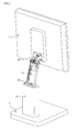
- FIG. 1 is a perspective view of a stand for a display device according to present invention showing a hinge connecting unit extruding from a slide housing
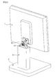
- FIG. 2 is a perspective view of a stand for a display device according to present invention showing a hinge connecting unit inserted in a slide housing.
- the stand for the display device includes a base 2 resting on a horizontal surface for supporting the display device 1, a slide housing 10 having one end fixed on the base 2 and a guiding member for moving the display device in a vertical direction with respect to the horizontal surface, and a hinge connecting unit 30 for moving in a vertical direction within the slide housing 10.
- the lower end of the hinge connecting unit 30 is connected to a guided unit 20 that moves vertically within the slide housing 10, and its upper end is coupled to a rear fixing unit 40 for supporting the display device.
- the hinge connecting unit 30 is fixed to a pivoting guided unit 20 that is guided along a guiding member within the slide housing 10, and moves in upward and downward directions by means of the guiding of the slide housing 10, in order to freely adjust the screen of the display device to a height desired by a user.
- the hinge connecting unit 30 couples through a hinge to the rear fixing unit 40 in order to support the display device at one end, and the other end of the hinge connecting unit 30 is pivotably connected to the guided unit 20 along the guiding member of the slide housing 10, so that a user of the display device can freely adjust the tilt angle and distance between the user and the screen.
- the base 2 of the display device according to the present invention has a wide surface area in order to securely support the display device 1 on a horizontal surface.
- the base 2 may be formed as a rectangular or discoid plate, may have an empty inner portion, and may be formed in a wide variety of designs.
- the slide housing 10 has a body that may be formed in a hollow cylindrical or multi-sided column.
- the body has the guiding member formed within that guides a vertical movement of the guided unit 20 coupled to the bottom of the hinge connecting unit 30, so that the position of the display device 1 may be adjusted vertically.
- the hinge connecting unit 30 is coupled to the guided unit 20 at a bottom thereof and moves vertically together with the guided unit 20 along the inside of the slide housing 10, due to the guided unit 20 moving vertically along a guiding member formed in the inner surface of the slide housing 10.
- the distance between the display device and a user may be freely adjusted due to the hinge connecting unit 30 being connected to the guided unit 20 via a hinge.
- the hinge connecting unit 30 is coupled to the rear fixing unit 40 for supporting the display device through a hinge (that is a pivotal point), the angle at which the screen is viewed and the distance between the screen and a user may be freely adjusted.
- the rear fixing unit 40 is interposed between the rear side of the display device and the hinge connecting unit 30 with a predetermined distance, so that the display device may be conveniently adjusted, when the hinge connecting unit 30 is inserted inside the slide housing 10.
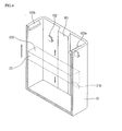
- a slide housing 10 is formed in a multi-sided, hollow column.
- a guiding member 101 for guiding the guided unit 20 is formed along the vertical length within the slide housing 10.
- Retaining ridges 103a and 103b are formed to protrude from the top inner surface on either side of the slide housing 10, to prevent the guided unit 20 sliding along the guiding member 101 from detaching from the slide housing 10.
- An elastic member holder 102 is provided at a predetermined location within the slide housing 10 for fixing an end of a plate spring 110 thereon.
- the plate spring 110 shown in detail in FIG. 5, expands or contracts by means of the guided unit 20, and elastically supports the guided unit 20.
- the plate spring 110 fixed on the elastic member holder 102 may be provided as two plate springs 111 and 112, as in one embodiment, or as a single plate spring. Of course, not only can a plate spring be used, but any other elastic member that can provide both elasticity and friction to the guided unit 20 may be used.
- Each plate spring 111 and 112 is respectively hooked and fastened to an elastic member holder 102 at a fixed portion 111a and 112a thereof, and has an elastic portion 111b and 112b that is formed in a spiral spring shape that winds and unwinds according to the movement of the guided unit 20 moving along the guiding member 101 within the slide housing 10. Specifically, in the above-described structure, the elastic portions 111b and 112b unwind and impart elasticity when the plate springs 111 and 112 are pressed by the guided unit 20.
- the fixed portions 111a and 112a of the plate springs 111 and 112 are fixed to the elastic member holders 102 in the slide housing 10, and the elastic portions 111b and 112b expand and contract according to the movement of the guided unit 20 along the guiding member 101.
- the plate springs 111 and 112, that are the elastic members used, are wound as a spiral spring type that maintain a uniform elasticity when pressed along a lengthwise direction.
- the fixed portions 111a and 112a of the plate springs 111 and 112 having the above characteristics are fixed on the elastic member holders 102 formed on the inside of the slide housing 10, and the elastic portions 111b and 112b thereof extend along the guiding member 101 formed perpendicularly on the inner surface of the slide housing 10 between the two sides thereof.
- the load of the display device is supported by the extending plate springs 111 and 112, which maintain the same elastic pressure regardless of their extended length and support the display at any adjusted height.
- the guided unit 20 is formed in a hexahedral shape with a surface that is cylindrically concaved to contact the outer surface of the elastic portions 111b and 112b of the cylindrically coiling plate springs 111 and 112.
- a guide fixing bracket 332 of the hinge connecting unit 30 is fastened and fixed to the top surface 220 of the guided unit 20, and the display device is moved upward and downward to adjust its height depending on the movement of the guided unit 20.
- the bottom of the guided unit 20 acts as a pusher to extend the plate spring 110 disposed therebelow.
- the user can grasp and pull or push the display device 1 downward.
- the force exerted to push or pull the display device 1 downward is transferred to the guided unit 20 coupled through a hinge to the bottom end of the hinge connecting unit 30 that is connected to the display device 1.
- the force transferred to the guided unit 20 exceeds the elastic force of the elastic members 111b and 112b, the elastic members 111b and 112b that are wound like a spiral spring are unraveled, allowing the guided unit 20 to move downward along the guiding member 101 formed on the inner surface of the slide housing 10.
- the user may grasp and move the display device 1 upward.
- the guided unit 20 moves upward along the vertically formed guiding member 101 within the slide housing 10 with respect to the surface on which the display device is placed.
- the elastic portions 111b and 112b are re-coiled and raised by their elasticity.
- the vertical movement of the above-described guided unit 20 along the guiding member 101 formed vertically within the slide housing 10 allows the display device to be moved vertically.
- the guided unit 20 stops moving.
- the expanding or contracting of the plate spring 110 also ceases.
- the elasticity in the plate spring 110 supports the load of the display device 1 so that the plate spring 110 stops moving.
- the display device 1 may be moved vertically due to the mechanism described above.
- the guided unit 20 is prevented from moving further upwards by the retaining ridges 103a and 103b.
- the retaining ridges 103a and 103b restrict adjustment of the display device 1 in an upward direction within the slide housing 10. Accordingly, it is possible to elevate the display device 1 to as far as the lengths of the guiding member 101 and the plate spring 110 and the position of the retaining ridges 103a and 103b allow.
- a hinge connecting unit 30 of a stand for a display device is coupled via a hinge at its lower end to the guided unit 20 that moves vertically inside the slide housing 10, and is coupled via a hinge at its upper end to the rear fixing unit 40 that is attached to a predetermined region of and supports the monitor of the display device 1.
- the rear fixing unit 40 is fixed to the rear surface 2 of the display device 1 to support the display device 1.
- the lower part of the hinge connecting unit 30 is connected to the guided unit 20 through the guide fixing bracket 332, and its upper part is connected to the rear fixing unit 40.
- a link is pivotably coupled to the rear fixing unit 40 by means of a link hinge portion, and the link is pivotably coupled to the guided unit 20 through hinge coupling by means of the guide hinge portion.
- the link includes a main link 310 pivotably connected at one end to the rear fixing unit 40 and pivotably connected at the other end to the guided unit 20 through the guide fixing bracket 332, a auxiliary link 320 disposed eccentrically to a pivoting center of the top of the main link 310 and pivotably connected to the guided unit 20 to move in unison with the main link 310 by means of the rear fixing unit 40 and the guide fixing bracket 332, and an elastic member 328 with one end fixed to the main link 310 and the other end fixed to the auxiliary link 320.
- the guide hinge portion includes a first and a second guide hinge portion 360 and 330 hinge-coupled to the guide fixing bracket 332 coupled to the guided unit 20, and a stopper 340 for sustaining an upright position of the main link 310 when the main link 310 is raised upright.
- the rear fixing unit 40 is pivotably connected to the main link 310 by means of the link hinge portion including the first and second link hinge portions 350 and 370.
- the main link 310 is pivotably connected to the guide fixing bracket 332 fixed to the guided unit 20 by means of the guide hinge portion including the first and second guide hinge portions 360 and 330.
- Both ends of the auxiliary link 320 are respectively installed on the second link hinge portion 350 and the first auxiliary link hinge portion located on the second guide hinge portion 330.
- one end of the spring 328 is connected to the main link 310, and the other end is connected to the side of the auxiliary link 320.
- a stopper 340 is installed on the second guide hinge portion 330 to sustain the main link 310 in a straight disposition when the main link 310 is straightened. A detailed description of the structure and operation of the stopper 340 will be given below.
- the rear fixing unit 40 includes a monitor supporting plate 412 fixed to the rear surface of the display device 1.
- the monitor supporting plate 412 defines a plurality of coupling holes 418 for coupling to the rear of the display device 1. Screws or other fasteners insert through the coupling holes 418 to fasten the monitor supporting plate 412 to the rear of the display device 1.
- a first hinge shaft 414 for forming the first link hinge portion 370 with the main link 310, and a second hinge hole 416 for inserting a second link hinge shaft 372 is formed below the supporting plate 412.
- the first hinge shaft 414 is mounted inside the first hinge receiving portion 382 of the main link 310.
- the first link hinge portion 370 is installed within the second hinge hole 416.
- the first link hinge portion 370 has a second hinge spring 371 for tilting the rear fixing unit 40, and a second hinge shaft 372 forming the hinge shaft for the second link hinge portion 350, mounted thereon.
- One end of the second hinge shaft 372 couples with the second link supporting shaft 352 that passes through the second hinge shaft receiving portion 312 formed on one end at the top of the main link 310 and extending from the inner surface of the second auxiliary link supporting portion 351.
- the second auxiliary link supporting portion 351 has second auxiliary link receiving portions 357 and 358 formed therein for receiving respective ends of the two auxiliary links 321 and 324 installed beside the main link 310.
- the two auxiliary links 321 and 324 may be parallel to one another.
- the points supporting the respective ends of the two auxiliary links 321 and 324 are offset from the pivoting center of the main link 310 by a predetermined distance.
- the ends of the two auxiliary links 321 and 324 are pivotably fixed to the second auxiliary link supporting portion 351 by second auxiliary link fixing shafts 354 and 355.
- the two other ends of the two auxiliary links 321 and 324 have through holes 323 and 326 formed therein.
- the two auxiliary links 321 and 324 are connected to a first auxiliary link supporting portion 331 through the through holes 323 and 326.
- First auxiliary link receiving portions 337 and 338 are formed in the first auxiliary link supporting portion 331 to receive the two auxiliary links 321 and 324.
- the other end portions of the two auxiliary links 321 and 324 are fastened in the first auxiliary link receiving portions 337 and 338 by first auxiliary link fastening shafts 335 and 336.
- the second guide hinge portion 330 is positioned under the first auxiliary link receiving portions 337 and 338 in order to fix the main link 310 via a hinge to the guide fixing bracket 332 fixed to the guided unit 20.
- the stopper 340 is formed to the side of the second guide hinge portion 330, in order to stop the pivoting movement of the main link 310 when the main link 310 is straightened. A description of the stopper 340 will be provided in detail below.
- the auxiliary links 321 and 324 are fixed to the first auxiliary link supporting portion 331 and the second auxiliary link supporting portion 351 in mutually different off-centered positions.
- the auxiliary links 321 and 324 and the auxiliary link supporting portions 331 and 351 collectively form a four bar link, namely quadric crank mechanism, that provides the conventional functions of a four bar link.
- the movement of the auxiliary links 321 and 324 causes the angle of the second auxiliary link supporting portion 351 to remain the same as that of the first auxiliary link supporting portion 331.
- the tilt angle of the display device 1 remains fixed and only its height is altered by means of the first auxiliary link supporting portion 331. This allows a user to retain a desired tilt angle of the display device 1 while moving it in other ways.
- the hinge on the upper portion of the hinge connecting unit 30 pivots so that the display device 1 rotates and changes its tilt angle.
- the elastic member 328 is installed to the inside of the first auxiliary link 324 that is the closer of the two auxiliary links 321 and 324 to the main link 310.
- the elastic member 328 has one end fixed on a second elastic member supporting protrusion 327 formed at the upper, inner portion of the first auxiliary link 324, and the other end of the elastic member 328 is fixed on a first elastic member supporting protrusion 317 formed on a lower side portion of the main link 310.
- the elastic member 328 maintains the auxiliary links 321 and 324 at a predetermined position with respect to one another, so that the auxiliary links move at a predetermined position. Therefore, when a user moves the display device 1 upward, only a small force can be used to move the display device 1.
- a first guide hinge receiving portion 315 and a second guide hinge receiving portion 316 are formed at the lower end of the main link 310, in order to pivotably connect the main link 310 to the guide fixing bracket 332 fixed to the guided unit 20.
- the first guide hinge portion 360 includes a first base hinge shaft 339 received in the first guide hinge receiving portion 315 of the main link 310 and a coil spring 349.
- the first base hinge shaft 362 passes successively through the first guide hinge receiving portion 315 and the coil spring 349, and is fastened.
- the elastic member 328 retains its original shape.
- the elastic member retains its minimum length (11), where its elasticity is also at its minimum.
- one end of the elastic member 328 fixed to an end of the main link 310 retains the same distance from pivoting point (B).
- the two auxiliary links 321 and 324 are not co-centric with pivoting point (B) of the main link 310, so that the other end of the elastic member 328 fixed to an end of the first auxiliary link 324 moves further away from pivoting point (B) of the main link 310.
- the elastic member 328 expands and imparts elasticity.
- the elasticity of the elastic member 328 imparts a restricting force on the pivoting motion of the main link 310.
- the weight of the display device 1 and the elasticity of the elastic member 328 combine to establish equilibrium, whereupon the display device 1 is fixed in that position.
- friction forces between each parts can be activated as a origin to stop the movement of the display device.
- the elastic member 328 attains a maximum length (12) and also a maximum level of elasticity.
- the stopper 340 When the main link 310 is completely erected, the stopper 340 according to the present invention automatically locks to maintain the main link 310 in the upright position. Thus, the user can easily push the hinge connecting unit 30 into the slide housing 10. The locking of the main link 310 by the stopper 340 will be described below in more detail.
- the elastic member 328 expands and contracts only at one of its ends - i.e., the end fixed to the auxiliary link.
- the elastic member 328 according to the present invention achieves the same position with a reduced amount of stretching.
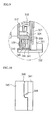
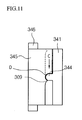
- the stopper 340 is a structure that automatically fixes the position of the main link 310 when the stand is erected. Referring to FIGs. 8 and 9, the structure of the stopper 340 will now be explained.
- the stopper 340 has a latch 341 and a rotating member 345.
- the latch 341 and the rotating member 345 are located on the side wall of the first auxiliary link supporting portion 331 and insert inside the second guide hinge receiving portion 316.
- the second base hinge shaft 339 is inserted through the opposite side of the second guide hinge receiving portion 316 and sequentially inserted through the coil spring 349, the rotating member 345, and the latch 341, and inserts into the second guide hinge shaft receiving portion 334.
- a latch fixing portion 333 and the second guide hinge shaft receiving portion 334 protrude from a side of the first auxiliary link fixing shafts.
- the second guide hinge shaft receiving portion 334 inserts into a latch shaft receiving portion 343 in the latch 341.
- a fixing recess 342 is formed in a surface of the latch 341. The fixing recess 342 inserts over the latch fixing portion 333, the latch 341 inserts over the second guide hinge shaft receiving portion 334, and to the guided unit 20 through the second guide fixing bracket 332.
- a protruding portion 344 is formed on the other side of the latch 341 (the side from which the second guide hinge shaft receiving portion 334 protrudes through).
- the protruding portion 344 may be formed on the peripheral region of the latch 341.
- the rotating member 345 rotates in unison with the main link 310.
- a rotating member shaft receiving portion 348 is formed in the center of the rotating member 345.
- the rotating member shaft receiving portion 348 is rotatively inserted and installed over the second guide hinge shaft receiving portion 334.
- the rotating member 345 contacts the latch 341 on at least one side thereof.
- a protrusion 346 is formed on the periphery of the rotating member 345.
- the protrusion 346 is fixed within the second guide hinge receiving portion 316. Accordingly, the rotating member 345 rotates when the main link 310 rotates.
- a radially cut portion 347 is formed on a surface of the rotating member 345 that the latch 341 contacts, so that when the rotating member 345 rotates, the protruding portion 344 of the latch 341 can move therein.
- the radially cut portion 347 is an extended recess cut in a radial direction along a surface of the rotating member 345 in a depth equal to the height of the protruding portion 344 of the latch 341.
- one end of the radially cut portion 347 is formed to contact the protruding portion 344 of the latch 341 when the main link 310 is horizontally disposed.
- a ledge 309 is formed at the lower end of the radially cut portion 347.
- the ledge 309 acts as a stopper for the protruding portion 344 of the latch 341 when the rotating member 345 rotates against the latch 341. A more detailed explanation thereof will be provided.
- the radially cut portion 347 of the rotating member 345 moves past the protruding portion 344 of the latch 341.
- the ledge 309 formed on a lower end of the radially cut portion 347 contacts the protruding portion 344.
- the ledge 309 may be designed to require a predetermined force to be exerted in order to move past the protruding portion 344.
- the main link 310 When a force required moving the ledge 309 past the protruding portion 344 is exerted, the main link 310 is completely locked.
- the protruding portion 344 formed on the latch 341 passes the ledge 309 of the rotating member 345, it rests in the resting groove (D) formed on a side of the radially cut portion 347 of the rotating member 345.
- the force of the ledge 309 supporting the protruding portion 344 of the latch 341 may be designed to be greater than the elastic force that the elastic member 328 installed on the auxiliary link imparts to straighten the main link 310 when folded.
- the main link 310 is stopped in its pivoting and fixed by the stopper 340 located at the bottom of the main link 310. In this way, the main link 310 is locked when it is extended. Accordingly, a user can not only know the exact position of a completely extended hinge connecting unit 30, but the extended position is reliably secured as well. Subsequently, the hinge connecting unit 30 can conveniently be inserted into the slide housing 10.
- a user can easily perform the extending of the hinge connecting unit 30, as well as the inserting of the hinge connecting unit 30 back into the slide housing 20 from an extended position.
- an excessive rearward bending of the hinge connecting unit 30 may be prevented.
- the hinge connecting unit 30 is inserted in the slide housing 10 so that the lower portion of the hinge connecting unit 30 cannot be moved on its hinge, and only the upper portion thereof may be pivoted on its hinge. Thus, the hinge between the rear fixing unit 40 and the hinge connecting unit 30 may be pivoted.
- FIG. 12 includes dotted lines showing the pivoting movement of the display device 1. This is a mode in which a user does not wish to alter the height of the display device 1, but may easily alter only its tilt angle thereof.
- the display device 1 when a user exerts a predetermined amount of force - specifically, a force in a direction for pivoting the hinge at the connecting portion of the hinge connecting unit and the rear fixing unit - the display device 1 may be tilted.
- This mode is suitable for adjusting the tilt angle of the display device 1 while it is in an elevated position.
- the display device may be adjusted by using the hinge at the lower portion of the hinge connecting unit as well.
- the hinge connecting unit of the stand for the display device according to the present invention is guided by the slide housing to move up and down, so that a user can freely adjust the height of the screen to a desired level. Furthermore, when the hinge connecting unit is extruded from the slide housing, the position of the display device may be adjusted in multiple ways to satisfy the user's preferences.
- the height of the display device, its tilt angle, and its distance from a user can be simultaneously adjusted.
Landscapes
- Engineering & Computer Science (AREA)
- General Engineering & Computer Science (AREA)
- Mechanical Engineering (AREA)
- Devices For Indicating Variable Information By Combining Individual Elements (AREA)
Applications Claiming Priority (1)
| Application Number | Priority Date | Filing Date | Title |
|---|---|---|---|
| KR1020060015875A KR101237570B1 (ko) | 2006-02-17 | 2006-02-17 | 디스플레이 기기의 스탠드 |
Publications (3)
| Publication Number | Publication Date |
|---|---|
| EP1821024A2 true EP1821024A2 (de) | 2007-08-22 |
| EP1821024A3 EP1821024A3 (de) | 2008-10-08 |
| EP1821024B1 EP1821024B1 (de) | 2019-01-02 |
Family
ID=38050132
Family Applications (1)
| Application Number | Title | Priority Date | Filing Date |
|---|---|---|---|
| EP06254028.1A Not-in-force EP1821024B1 (de) | 2006-02-17 | 2006-08-01 | Ständer für Anzeigevorrichtung |
Country Status (4)
| Country | Link |
|---|---|
| US (1) | US7694919B2 (de) |
| EP (1) | EP1821024B1 (de) |
| KR (1) | KR101237570B1 (de) |
| CN (1) | CN101026017A (de) |
Families Citing this family (44)
| Publication number | Priority date | Publication date | Assignee | Title |
|---|---|---|---|---|
| AU2003292710A1 (en) * | 2003-01-09 | 2004-08-10 | Sharp Kabushiki Kaisha | Thin display device and method of pulling out display part |
| TWI289633B (en) * | 2005-05-23 | 2007-11-11 | Avision Inc | Self locking hinge |
| TWI323806B (en) * | 2005-12-23 | 2010-04-21 | Innolux Display Corp | Monitor with stand |
| KR101300990B1 (ko) * | 2007-01-02 | 2013-08-27 | 엘지전자 주식회사 | 디스플레이 기기 |
| US20080164398A1 (en) * | 2007-01-08 | 2008-07-10 | Samsung Electro-Mechanics Co., Ltd. | Display support apparatus |
| KR101372268B1 (ko) * | 2007-02-13 | 2014-03-11 | 삼성전자주식회사 | 디스플레이장치용 지지장치 및 이를 갖춘 디스플레이장치 |
| JP4582132B2 (ja) * | 2007-08-28 | 2010-11-17 | ソニー株式会社 | L字スタンド |
| KR101414618B1 (ko) * | 2007-10-23 | 2014-07-03 | 엘지전자 주식회사 | 디스플레이장치의 스탠드 |
| KR100922872B1 (ko) * | 2008-01-07 | 2009-10-20 | 곽수만 | 디스플레이장치용 암 스탠드 |
| US8274615B2 (en) * | 2008-03-07 | 2012-09-25 | Audiovox Corporation | Mobile video system |
| CN101713487B (zh) * | 2008-10-08 | 2013-06-05 | 鸿富锦精密工业(深圳)有限公司 | 升降机构 |
| CN101725804B (zh) * | 2008-10-17 | 2012-06-20 | 鸿富锦精密工业(深圳)有限公司 | 铰链结构 |
| CN101737602B (zh) * | 2008-11-17 | 2012-08-29 | 鸿富锦精密工业(深圳)有限公司 | 支撑机构及采用该支撑机构的升降机构 |
| CN101749525B (zh) * | 2008-12-15 | 2012-05-30 | 鸿富锦精密工业(深圳)有限公司 | 支撑机构 |
| CN101922598B (zh) * | 2009-06-17 | 2012-07-25 | 鸿富锦精密工业(深圳)有限公司 | 支座 |
| KR20110026655A (ko) * | 2009-09-08 | 2011-03-16 | 삼성전자주식회사 | 영상표시장치의 승강유닛 및 이를 갖는 영상표시장치 |
| WO2011071856A2 (en) | 2009-12-07 | 2011-06-16 | Ergotron, Inc. | Brake stand systems |
| JP4923121B2 (ja) * | 2010-02-25 | 2012-04-25 | 東芝テック株式会社 | ディスプレイ装置及びディスプレイ装置システム |
| KR101682723B1 (ko) * | 2010-08-20 | 2016-12-05 | 엘지전자 주식회사 | 디스플레이 기기의 스탠드 장치 |
| US8611076B2 (en) * | 2011-01-13 | 2013-12-17 | Autumn Horizons, Inc. | Multi-positional stand and under cabinet mount for a tablet computer |
| US8576553B2 (en) * | 2011-05-17 | 2013-11-05 | Myerchin Enterprises, Inc. | Base with counterweight for display screens |
| US8570723B2 (en) | 2011-05-18 | 2013-10-29 | Myerchin Enterprises, Inc. | Actuated hinge and cable assembly for use with computer display monitors |
| US9291299B2 (en) * | 2011-08-31 | 2016-03-22 | Hewlett-Packard Development Company, L.P. | Display stand with latching mechanism |
| US9456511B2 (en) | 2012-10-30 | 2016-09-27 | Hewlett-Packard Development Company, L.P. | Support assembly for a device |
| US9255661B2 (en) | 2013-05-31 | 2016-02-09 | Hewlett-Packard Development Company, L.P. | Adjusters to control lower joints and upper joints |
| US9618976B2 (en) * | 2013-12-10 | 2017-04-11 | Lenovo (Singapore) Pte. Ltd. | Hinged computer stand that slides up and down on a video display |
| CN204127585U (zh) * | 2014-09-29 | 2015-01-28 | 纬创资通股份有限公司 | 可定位的升降支架结构 |
| TWM513310U (zh) * | 2015-08-21 | 2015-12-01 | Syncmold Entpr Corp | 用以支撐顯示裝置的支撐座 |
| US10345851B2 (en) | 2016-04-14 | 2019-07-09 | Microsoft Technology Licensing, Llc | Device with a rotatable display |
| US10172248B1 (en) * | 2016-04-14 | 2019-01-01 | Microsoft Technology Licensing, Llc | Device with a rotatable display |
| US10159158B2 (en) | 2016-04-14 | 2018-12-18 | Microsoft Technology Licensing, Llc | Device with a rotatable display |
| US9936593B2 (en) | 2016-04-14 | 2018-04-03 | Microsoft Technology Licensing, Llc | Device with a rotatable display |
| US10996710B2 (en) | 2016-04-14 | 2021-05-04 | Microsoft Technology Licensing, Llc | Device with a rotatable display |
| US10999944B2 (en) | 2016-04-26 | 2021-05-04 | Microsoft Technology Licensing, Llc | Structural device cover |
| US9946309B2 (en) | 2016-06-10 | 2018-04-17 | Microsoft Technology Licensing, Llc | Device wiring |
| US10221898B2 (en) | 2016-07-01 | 2019-03-05 | Microsoft Technology Licensing, Llc | Hinge clutch |
| CN106354210A (zh) * | 2016-08-31 | 2017-01-25 | 同方计算机有限公司 | 一种带有升降结构的显示器 |
| CA3004672A1 (en) | 2017-06-09 | 2018-12-09 | Teknion Limited | Adjustable counterbalancing display support |
| CN110764571B (zh) * | 2018-07-27 | 2024-12-31 | 中国长城科技集团股份有限公司 | 一体式计算机 |
| US11334111B2 (en) | 2018-11-02 | 2022-05-17 | Lg Electronics Inc. | Display device |
| CN111010912B (zh) * | 2019-12-20 | 2022-03-29 | 洛阳福格森机械装备有限公司 | 一种微耕机的犁耙农具调深连接装置 |
| CN113790372B (zh) * | 2021-07-19 | 2022-09-02 | 荣耀终端有限公司 | 屏幕壁挂装置 |
| KR102772253B1 (ko) | 2023-06-22 | 2025-02-25 | 동오정밀 주식회사 | 모니터용 듀얼 힌지장치 |
| KR102797491B1 (ko) * | 2023-08-31 | 2025-04-23 | 엘지전자 주식회사 | 디스플레이 디바이스 |
Citations (5)
| Publication number | Priority date | Publication date | Assignee | Title |
|---|---|---|---|---|
| JPH11316556A (ja) | 1998-05-01 | 1999-11-16 | Sony Corp | 収納式表示装置 |
| US6712321B1 (en) | 2003-05-21 | 2004-03-30 | Compal Electronics, Inc. | Adjustable supporting device for a display panel |
| US20050002159A1 (en) | 2002-09-28 | 2005-01-06 | Samsung Electronics Co., Ltd. | Monitor |
| US20050247832A1 (en) | 2004-05-06 | 2005-11-10 | Lg Electronics Inc. | Stand assembly for monitor |
| US20060000955A1 (en) | 2004-06-14 | 2006-01-05 | Sava Cvek | Extension and retraction arrangements |
Family Cites Families (15)
| Publication number | Priority date | Publication date | Assignee | Title |
|---|---|---|---|---|
| KR100443979B1 (ko) * | 2001-10-24 | 2004-08-09 | 삼성전자주식회사 | 케이블 내장형 lcd모니터 스탠드 |
| AU2002222629A1 (en) * | 2001-12-13 | 2003-06-23 | Murakami Corporation | Direction regulator of display |
| KR100520060B1 (ko) * | 2002-05-28 | 2005-10-11 | 삼성전자주식회사 | 모니터장치 |
| KR100435232B1 (ko) * | 2002-08-09 | 2004-06-11 | 엘지전자 주식회사 | Lcd 모니터의 받침대 구조 |
| TW543017B (en) * | 2002-09-20 | 2003-07-21 | Benq Corp | Monitor with changeable stand |
| JP3757217B2 (ja) * | 2003-05-06 | 2006-03-22 | 株式会社ナナオ | 液晶ディスプレイ用のスタンド |
| KR100534120B1 (ko) * | 2003-08-21 | 2005-12-08 | 삼성전자주식회사 | 모니터장치 |
| JP4402448B2 (ja) * | 2003-12-24 | 2010-01-20 | 株式会社新鋭産業 | ディスプレイモニター用スタンド |
| US7036787B1 (en) * | 2005-02-04 | 2006-05-02 | Taiwan Thick-Film Ind. Corp. | Display strut adjusting structure |
| TWM281256U (en) * | 2005-02-24 | 2005-11-21 | Compal Electronics Inc | Supporting structure for display monitor |
| US7193843B2 (en) * | 2005-04-19 | 2007-03-20 | Amtran Technology Co., Ltd. | Display device with a bracket covering |
| KR100697446B1 (ko) * | 2005-08-04 | 2007-03-20 | 엘지전자 주식회사 | 영상 디스플레이 장치의 스탠드 |
| KR100846898B1 (ko) * | 2005-12-30 | 2008-07-17 | 엘지전자 주식회사 | 영상 디스플레이 기기의 스탠드 |
| TWM300950U (en) * | 2006-05-11 | 2006-11-11 | Jarllytec Co Ltd | Vertically adjustable rotary axle mechanism |
| US7413150B1 (en) * | 2007-06-19 | 2008-08-19 | Shin Zu Shing Co., Ltd. | Flat panel display stand |
-
2006
- 2006-02-17 KR KR1020060015875A patent/KR101237570B1/ko not_active Expired - Lifetime
- 2006-07-14 US US11/486,032 patent/US7694919B2/en active Active
- 2006-08-01 EP EP06254028.1A patent/EP1821024B1/de not_active Not-in-force
- 2006-08-28 CN CNA2006101257615A patent/CN101026017A/zh active Pending
Patent Citations (5)
| Publication number | Priority date | Publication date | Assignee | Title |
|---|---|---|---|---|
| JPH11316556A (ja) | 1998-05-01 | 1999-11-16 | Sony Corp | 収納式表示装置 |
| US20050002159A1 (en) | 2002-09-28 | 2005-01-06 | Samsung Electronics Co., Ltd. | Monitor |
| US6712321B1 (en) | 2003-05-21 | 2004-03-30 | Compal Electronics, Inc. | Adjustable supporting device for a display panel |
| US20050247832A1 (en) | 2004-05-06 | 2005-11-10 | Lg Electronics Inc. | Stand assembly for monitor |
| US20060000955A1 (en) | 2004-06-14 | 2006-01-05 | Sava Cvek | Extension and retraction arrangements |
Also Published As
| Publication number | Publication date |
|---|---|
| US20070194182A1 (en) | 2007-08-23 |
| CN101026017A (zh) | 2007-08-29 |
| EP1821024A3 (de) | 2008-10-08 |
| KR101237570B1 (ko) | 2013-02-26 |
| EP1821024B1 (de) | 2019-01-02 |
| KR20070082792A (ko) | 2007-08-22 |
| US7694919B2 (en) | 2010-04-13 |
Similar Documents
| Publication | Publication Date | Title |
|---|---|---|
| EP1821024B1 (de) | Ständer für Anzeigevorrichtung | |
| US7497410B2 (en) | Stand of a display device | |
| US7669812B2 (en) | Stand for display device | |
| US7677509B2 (en) | Monitor stand | |
| US20070205340A1 (en) | Supporting device for display units | |
| US7578490B2 (en) | Stand of display device | |
| US6822857B2 (en) | Monitor improved in a tilting structure | |
| KR100684998B1 (ko) | 모니터장치 | |
| KR100705063B1 (ko) | 영상 디스플레이 장치의 스탠드 | |
| US7717384B2 (en) | Stand of display device | |
| EP1855045A1 (de) | Ständer für Anzeigeeinheit | |
| US7494099B2 (en) | Wall mount usable with display apparatus | |
| EP1821029A2 (de) | Ständer und hiermit versehene Anzeigevorrichtung | |
| EP1783419B1 (de) | Höhenverstellvorrichtung einer Anzeigevorrichtung und Ständer für eine Anzeigevorrichtung | |
| KR100765242B1 (ko) | 평판형 tv용 벽걸이식 거치대 | |
| KR20030004967A (ko) | 엘씨디의 높낮이 조절장치 | |
| KR100826198B1 (ko) | 영상표시장치 | |
| KR100465798B1 (ko) | 모니터장치 | |
| KR100628118B1 (ko) | 평판형 모니터 | |
| KR100632739B1 (ko) | 모니터장치 | |
| JP2000170472A (ja) | 天井用はしご装置 |
Legal Events
| Date | Code | Title | Description |
|---|---|---|---|
| PUAI | Public reference made under article 153(3) epc to a published international application that has entered the european phase |
Free format text: ORIGINAL CODE: 0009012 |
|
| AK | Designated contracting states |
Kind code of ref document: A2 Designated state(s): AT BE BG CH CY CZ DE DK EE ES FI FR GB GR HU IE IS IT LI LT LU LV MC NL PL PT RO SE SI SK TR |
|
| AX | Request for extension of the european patent |
Extension state: AL BA HR MK YU |
|
| PUAL | Search report despatched |
Free format text: ORIGINAL CODE: 0009013 |
|
| AK | Designated contracting states |
Kind code of ref document: A3 Designated state(s): AT BE BG CH CY CZ DE DK EE ES FI FR GB GR HU IE IS IT LI LT LU LV MC NL PL PT RO SE SI SK TR |
|
| AX | Request for extension of the european patent |
Extension state: AL BA HR MK RS |
|
| 17P | Request for examination filed |
Effective date: 20081124 |
|
| 17Q | First examination report despatched |
Effective date: 20090113 |
|
| AKX | Designation fees paid |
Designated state(s): DE FR GB |
|
| REG | Reference to a national code |
Ref country code: DE Ref legal event code: R079 Ref document number: 602006057191 Country of ref document: DE Free format text: PREVIOUS MAIN CLASS: F16M0011040000 Ipc: F16M0011100000 |
|
| RIC1 | Information provided on ipc code assigned before grant |
Ipc: F16M 11/10 20060101AFI20180420BHEP Ipc: F16M 11/24 20060101ALI20180420BHEP |
|
| GRAP | Despatch of communication of intention to grant a patent |
Free format text: ORIGINAL CODE: EPIDOSNIGR1 |
|
| INTG | Intention to grant announced |
Effective date: 20180612 |
|
| GRAS | Grant fee paid |
Free format text: ORIGINAL CODE: EPIDOSNIGR3 |
|
| GRAJ | Information related to disapproval of communication of intention to grant by the applicant or resumption of examination proceedings by the epo deleted |
Free format text: ORIGINAL CODE: EPIDOSDIGR1 |
|
| GRAL | Information related to payment of fee for publishing/printing deleted |
Free format text: ORIGINAL CODE: EPIDOSDIGR3 |
|
| GRAR | Information related to intention to grant a patent recorded |
Free format text: ORIGINAL CODE: EPIDOSNIGR71 |
|
| INTC | Intention to grant announced (deleted) | ||
| GRAA | (expected) grant |
Free format text: ORIGINAL CODE: 0009210 |
|
| REG | Reference to a national code |
Ref country code: DE Ref legal event code: R081 Ref document number: 602006057191 Country of ref document: DE Owner name: LG ELECTRONICS INC., KR Free format text: FORMER OWNER: LG ELECTRONICS INC., SEOUL, KR |
|
| AK | Designated contracting states |
Kind code of ref document: B1 Designated state(s): DE FR GB |
|
| INTG | Intention to grant announced |
Effective date: 20181123 |
|
| REG | Reference to a national code |
Ref country code: GB Ref legal event code: FG4D |
|
| REG | Reference to a national code |
Ref country code: DE Ref legal event code: R096 Ref document number: 602006057191 Country of ref document: DE |
|
| REG | Reference to a national code |
Ref country code: DE Ref legal event code: R097 Ref document number: 602006057191 Country of ref document: DE |
|
| PLBE | No opposition filed within time limit |
Free format text: ORIGINAL CODE: 0009261 |
|
| STAA | Information on the status of an ep patent application or granted ep patent |
Free format text: STATUS: NO OPPOSITION FILED WITHIN TIME LIMIT |
|
| 26N | No opposition filed |
Effective date: 20191003 |
|
| GBPC | Gb: european patent ceased through non-payment of renewal fee |
Effective date: 20190801 |
|
| PG25 | Lapsed in a contracting state [announced via postgrant information from national office to epo] |
Ref country code: FR Free format text: LAPSE BECAUSE OF NON-PAYMENT OF DUE FEES Effective date: 20190831 |
|
| PG25 | Lapsed in a contracting state [announced via postgrant information from national office to epo] |
Ref country code: GB Free format text: LAPSE BECAUSE OF NON-PAYMENT OF DUE FEES Effective date: 20190801 |
|
| PGFP | Annual fee paid to national office [announced via postgrant information from national office to epo] |
Ref country code: DE Payment date: 20240705 Year of fee payment: 19 |
|
| REG | Reference to a national code |
Ref country code: DE Ref legal event code: R119 Ref document number: 602006057191 Country of ref document: DE |