EP1829708B1 - Dekorfolie, dekorierter geformter artikel und motorfahrzeug - Google Patents
Dekorfolie, dekorierter geformter artikel und motorfahrzeug Download PDFInfo
- Publication number
- EP1829708B1 EP1829708B1 EP06797400A EP06797400A EP1829708B1 EP 1829708 B1 EP1829708 B1 EP 1829708B1 EP 06797400 A EP06797400 A EP 06797400A EP 06797400 A EP06797400 A EP 06797400A EP 1829708 B1 EP1829708 B1 EP 1829708B1
- Authority
- EP
- European Patent Office
- Prior art keywords
- decorative sheet
- formed product
- adhesive layer
- flow reducing
- base member
- Prior art date
- Legal status (The legal status is an assumption and is not a legal conclusion. Google has not performed a legal analysis and makes no representation as to the accuracy of the status listed.)
- Not-in-force
Links
Images


Classifications
-
- B—PERFORMING OPERATIONS; TRANSPORTING
- B60—VEHICLES IN GENERAL
- B60R—VEHICLES, VEHICLE FITTINGS, OR VEHICLE PARTS, NOT OTHERWISE PROVIDED FOR
- B60R13/00—Elements for body-finishing, identifying, or decorating; Arrangements or adaptations for advertising purposes
-
- B—PERFORMING OPERATIONS; TRANSPORTING
- B44—DECORATIVE ARTS
- B44C—PRODUCING DECORATIVE EFFECTS; MOSAICS; TARSIA WORK; PAPERHANGING
- B44C1/00—Processes, not specifically provided for elsewhere, for producing decorative surface effects
- B44C1/10—Applying flat materials, e.g. leaflets, pieces of fabrics
- B44C1/105—Applying flat materials, e.g. leaflets, pieces of fabrics comprising an adhesive layer
-
- B—PERFORMING OPERATIONS; TRANSPORTING
- B44—DECORATIVE ARTS
- B44C—PRODUCING DECORATIVE EFFECTS; MOSAICS; TARSIA WORK; PAPERHANGING
- B44C5/00—Processes for producing special ornamental bodies
-
- B—PERFORMING OPERATIONS; TRANSPORTING
- B60—VEHICLES IN GENERAL
- B60R—VEHICLES, VEHICLE FITTINGS, OR VEHICLE PARTS, NOT OTHERWISE PROVIDED FOR
- B60R13/00—Elements for body-finishing, identifying, or decorating; Arrangements or adaptations for advertising purposes
- B60R13/02—Internal Trim mouldings ; Internal Ledges; Wall liners for passenger compartments; Roof liners
-
- C—CHEMISTRY; METALLURGY
- C09—DYES; PAINTS; POLISHES; NATURAL RESINS; ADHESIVES; COMPOSITIONS NOT OTHERWISE PROVIDED FOR; APPLICATIONS OF MATERIALS NOT OTHERWISE PROVIDED FOR
- C09J—ADHESIVES; NON-MECHANICAL ASPECTS OF ADHESIVE PROCESSES IN GENERAL; ADHESIVE PROCESSES NOT PROVIDED FOR ELSEWHERE; USE OF MATERIALS AS ADHESIVES
- C09J7/00—Adhesives in the form of films or foils
- C09J7/20—Adhesives in the form of films or foils characterised by their carriers
- C09J7/22—Plastics; Metallised plastics
-
- C—CHEMISTRY; METALLURGY
- C09—DYES; PAINTS; POLISHES; NATURAL RESINS; ADHESIVES; COMPOSITIONS NOT OTHERWISE PROVIDED FOR; APPLICATIONS OF MATERIALS NOT OTHERWISE PROVIDED FOR
- C09J—ADHESIVES; NON-MECHANICAL ASPECTS OF ADHESIVE PROCESSES IN GENERAL; ADHESIVE PROCESSES NOT PROVIDED FOR ELSEWHERE; USE OF MATERIALS AS ADHESIVES
- C09J7/00—Adhesives in the form of films or foils
- C09J7/20—Adhesives in the form of films or foils characterised by their carriers
- C09J7/29—Laminated material
-
- C—CHEMISTRY; METALLURGY
- C09—DYES; PAINTS; POLISHES; NATURAL RESINS; ADHESIVES; COMPOSITIONS NOT OTHERWISE PROVIDED FOR; APPLICATIONS OF MATERIALS NOT OTHERWISE PROVIDED FOR
- C09J—ADHESIVES; NON-MECHANICAL ASPECTS OF ADHESIVE PROCESSES IN GENERAL; ADHESIVE PROCESSES NOT PROVIDED FOR ELSEWHERE; USE OF MATERIALS AS ADHESIVES
- C09J7/00—Adhesives in the form of films or foils
- C09J7/30—Adhesives in the form of films or foils characterised by the adhesive composition
- C09J7/35—Heat-activated
-
- B—PERFORMING OPERATIONS; TRANSPORTING
- B60—VEHICLES IN GENERAL
- B60R—VEHICLES, VEHICLE FITTINGS, OR VEHICLE PARTS, NOT OTHERWISE PROVIDED FOR
- B60R13/00—Elements for body-finishing, identifying, or decorating; Arrangements or adaptations for advertising purposes
- B60R13/02—Internal Trim mouldings ; Internal Ledges; Wall liners for passenger compartments; Roof liners
- B60R13/0206—Arrangements of fasteners and clips specially adapted for attaching inner vehicle liners or mouldings
-
- C—CHEMISTRY; METALLURGY
- C09—DYES; PAINTS; POLISHES; NATURAL RESINS; ADHESIVES; COMPOSITIONS NOT OTHERWISE PROVIDED FOR; APPLICATIONS OF MATERIALS NOT OTHERWISE PROVIDED FOR
- C09J—ADHESIVES; NON-MECHANICAL ASPECTS OF ADHESIVE PROCESSES IN GENERAL; ADHESIVE PROCESSES NOT PROVIDED FOR ELSEWHERE; USE OF MATERIALS AS ADHESIVES
- C09J2301/00—Additional features of adhesives in the form of films or foils
- C09J2301/10—Additional features of adhesives in the form of films or foils characterized by the structural features of the adhesive tape or sheet
- C09J2301/16—Additional features of adhesives in the form of films or foils characterized by the structural features of the adhesive tape or sheet by the structure of the carrier layer
- C09J2301/162—Additional features of adhesives in the form of films or foils characterized by the structural features of the adhesive tape or sheet by the structure of the carrier layer the carrier being a laminate constituted by plastic layers only
-
- Y—GENERAL TAGGING OF NEW TECHNOLOGICAL DEVELOPMENTS; GENERAL TAGGING OF CROSS-SECTIONAL TECHNOLOGIES SPANNING OVER SEVERAL SECTIONS OF THE IPC; TECHNICAL SUBJECTS COVERED BY FORMER USPC CROSS-REFERENCE ART COLLECTIONS [XRACs] AND DIGESTS
- Y10—TECHNICAL SUBJECTS COVERED BY FORMER USPC
- Y10T—TECHNICAL SUBJECTS COVERED BY FORMER US CLASSIFICATION
- Y10T428/00—Stock material or miscellaneous articles
- Y10T428/24—Structurally defined web or sheet [e.g., overall dimension, etc.]
- Y10T428/24479—Structurally defined web or sheet [e.g., overall dimension, etc.] including variation in thickness
- Y10T428/24612—Composite web or sheet
Definitions
- the present invention relates to a decorative sheet for use to decorate a formed product and also relates to a formed product decorated with such a decorative sheet and to a motor vehicle including such a decorated formed product.
- a decorative sheet be attached to the surface of a formed product as a technique of decorating various types of formed products.
- a formed product with a decorative sheet can be recycled more easily than a formed product with a painted surface.
- a decorated product can have a different type of fine appearance from that of a painted product. That is why a decorative sheet contributes to improving the appearance of formed products noticeably.
- FIG. 18 shows an example of a decorative sheet.
- the decorative sheet 110 shown in FIG. 18 includes a base member 1 of a resin material, a decoration layer 2 arranged on the principal surface 1a of the base member 1, and an adhesive layer 4 deposited on the decoration layer 2.
- the decoration layer 2 may be formed by a printing process, for example.
- the adhesive layer 4 may be formed by dry-laminating a resin adhesive, for instance.
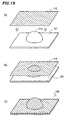
- the formed product 121 shown in FIG. 19(a) includes a hemispherical (cuplike) raised portion 121a and therefore has a rugged surface. For that reason, the decorative sheet 110 being attached is stretched so as to follow such ruggedness perfectly. To stretch the decorative sheet 110 effectively, the decorative sheet 110 is typically heated and softened before being attached.
- a vacuum forming system for making a decorated formed product 120 such as that shown in FIG. 19(c) by using the decorative sheet 110 is disclosed in Patent Document No. 1, for example.
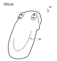
- FIG. 20 shows a motorcycle fender 122 decorated with the decorative sheet 110. As shown in FIG. 20 , a string of uneven gloss 123 appears on a part of the surface of the fender 122 to ruin the beautiful appearance thereof.
- the present invention has an object of providing a decorative sheet that can decorate a formed product without diminishing the beauty of its appearance, a formed product decorated with such a decorative sheet, and a motor vehicle including such a decorated formed product.
- a decorative sheet according to the present invention is used to decorate a formed product.
- the sheet includes: a decoration layer; a base member that supports the decoration layer; an adhesive layer for adhering the decoration layer and the base member onto the formed product; and a flow reducing member for reducing the flow of the adhesive layer.
- the flow reducing member is provided in the adhesive layer and is made of a material having a higher melting point than that of a material of the adhesive layer, thereby achieving the object described above.
- the flow reducing member is fixed on the decoration layer.
- the adhesive layer is arranged so as to cover the decoration layer and the flow reducing member that is fixed on the decoration layer.
- the melting point of the material of the flow reducing member is higher than that of the material of the adhesive layer by at least 20 °C.
- the elasticity of the material of the flow reducing member is at least twice as high as that of the material of the adhesive layer at 80 °C.
- the flow reducing member has a recess on its surface that is in contact with the adhesive layer.
- the thinnest portion of the flow reducing member with the recess is at most two-thirds as thick as the thickest portion thereof.
- the decorative sheet according to the present invention includes a plurality of flow reducing members.
- the flow reducing members are arranged at regular intervals.
- the melting point of the material of the adhesive layer is lower than the glass transition temperature of the material of the base member by at least 30 °C.
- the material of the base member is a resin.
- the resin is a thermoplastic resin.
- a decorated formed product according to the present invention includes: a formed product; and a decorative sheet that has been bonded to the surface of the formed product and has one of the structures described above, thereby achieving the object described above.
- the formed product has been formed by a deep-drawing process and has such a shape that a draw diameter L and a draw depth D satisfy L ⁇ 100 mm and D/L ⁇ 1/3.
- an outer surface of the decorative sheet bonded to the surface of the formed product has ruggedness corresponding to an arrangement pattern of the flow reducing members.
- a motor vehicle according to the present invention includes a decorated formed product having one of the structures described above, thereby achieving the object described above.
- a decorative sheet according to the present invention includes a flow reducing member that reduces the flow of the adhesive layer. That is why when the sheet is bonded onto a formed product, the adhesive is rarely distributed unevenly and a string of uneven gloss can be virtually eliminated. Consequently, a formed product can be decorated with the decorative sheet of the present invention without diminishing the beauty of its appearance.
- FIGS. 21(a) through 21(c) illustrate a conventional decorated formed product manufacturing process.
- a decorative sheet 110 is fixed onto a gripping frame 30 and then heated with a heater 33.
- the decorative sheet 110 is heated to a temperature at which the base member 1 softens sufficiently and the adhesive layer 4 has good adhesiveness.
- the gripping frame 30 is brought down to press the decorative sheet 110 against a formed product 121.
- a portion 110a of the decorative sheet 110 is attached to the formed product 121 as shown in FIG. 21(b) .
- the decorative sheet 110 is pressurized by introducing compressed air into the space over the decorative sheet 110.
- the other portion 110b of the decorative sheet 110 is also bonded onto the formed product 121, which is now covered entirely with the decorative sheet 110 as shown in FIG. 21(c) .
- excessive portions of the decorative sheet 110 are cut off to complete a decorated formed product.
- the portion 110a of the decorative sheet 110 that contacts with the formed product 121 earlier is cooled more quickly due to conduction of heat into the formed product 121 than the other portion 110b that contacts with the formed product 121 later.
- the portion 110b that is still out of contact with the formed product 121 has a temperature of 150 °C to 170 °C, but the temperature of that portion 110a in contact with the formed product 121 decreases to somewhere between 60 °C and 120 °C, in the process step shown in FIG. 21(b) . That is why the flowability of the adhesive is lower in the portion 110a in contact with the formed product 121 than in the non-contacting portion 110b.
- the base member 1 of the decorative sheet 110 is once stretched so as to fit the surface shape of the formed product 121 closely and then is cooled and shrinks.
- FIG. 21(b) shows the direction in which the base member 1 is stretched and the direction in which the base member 1 shrinks.
- the adhesive in the adhesive layer 4 on the base member 1 flows in the direction in which the base member 1 shrinks.
- the shifted adhesive stays in the vicinity of the boundary between a region where the adhesive has high flowability (i.e., the portion 110b that will contact with the formed product 121 later) and a region where the adhesive has low flowability (i.e., the portion 110a that has already contacted with the formed product 121).
- the adhesive layer 4 gets raised around that boundary. Consequently, the decoration layer 2 and the base member 1 located over the adhesive layer 4 also get raised just like the adhesive layer 4, thus making a string of uneven gloss sensible.
- the uneven distribution of the adhesive will produce the uneven gloss and diminish the beauty of its appearance.
- FIG. 1 schematically illustrates a decorative sheet 10 according to this preferred embodiment.
- the decorative sheet 10 of this preferred embodiment includes a decoration layer 2, a base member 1 that supports the decoration layer 2, and an adhesive layer 4 for bonding the decoration layer 2 and the base member 1 to a formed product.
- the decoration layer 2 is arranged on one 1a of the two principal surfaces of the base member 1.
- the decoration layer 2 may be formed by printing ink, for example.
- the decorative sheet 10 is heated and stretched when attached onto the formed product. That is why the material of the decoration layer 2 preferably has excellent thermal resistance and bend strength.
- the ink disclosed in Japanese Patent Application Laid-Open Publication No. 2002-275405 has excellent thermal resistance and bend strength, and therefore, can be used effectively as the material of the decoration layer 2.
- the base member 1 is made of a resin, and typically made of a thermoplastic resin such as polycarbonate or acrylic resin.
- the base member 1 should have some degree of rigidity that is high enough to serve as a sheet base member. That is why the material is preferably selected in view of this respect.
- the base member 1 since the base member 1 will be located on the uppermost surface of the formed product after the decorative sheet 10 is attached to the formed product, the base member 1 preferably has good weather resistance and good damage resistance. For that reason, the other principal surface of the base member 1, which is opposite to the principal surface 1a with the decoration layer 2, may be covered with a protective layer with good weather resistance and good damage resistance.
- the base member 1 preferably has a thickness of no less than 50 ⁇ m and no more than 1,000 ⁇ m. This is because if the base member 1 had a thickness of less than 50 ⁇ m, the sheet would be difficult to handle or its mechanical strength could be too low to avoid tears when the sheet is being attached. On the other hand, if the thickness of the base member 1 exceeded 1,000 ⁇ m, then the sheet could not fit closely the surface of the formed product.
- the adhesive layer 4 is made of a urethane adhesive of a urethane resin or a urethane acrylate resin or an acrylic adhesive.
- the adhesive in the adhesive layer 4 preferably has an elasticity of 1 ⁇ 10 3 Pa to 1 ⁇ 10 6 Pa at 80 °C. If the elasticity at 80 °C were lower than 1 ⁇ 10 3 Pa, then the adhesive would soften so much as to cause some problems when the product is used at a high temperature (e.g., when used outdoors in summer). On the other hand, if the elasticity at 80 °C were higher than 1 ⁇ 10 6 Pa, then the adhesive would be too hard to resist impact.
- the adhesive preferably has an elasticity of 1 ⁇ 10 1 Pa to 1 ⁇ 10 5 Pa at 180 °C.
- This temperature range is preferred for the following reasons. Specifically, if the elasticity at 180 °C were less than 1 ⁇ 10 1 , Pa, then the adhesive would flow so easily during the forming process that a pattern representing the adhesive flow could appear on the surface of the formed product. On the other hand, if the elasticity at 180 °C were higher than 1 ⁇ 10 5 Pa, bubbles would be easily produced between the adhesive layer 4 and the formed product when the decorative sheet 10 is being attached.
- the elasticity of the adhesive may be measured by a solid viscosity/elasticity measuring method compliant with JIS K7244-6 (or ISO 6721), for example.
- the adhesive layer 4 preferably has a thickness of no less than 30 ⁇ m and no more than 100 ⁇ m. If the adhesive layer 4 had a thickness of less than 30 ⁇ m, then the adhesive layer 4 could become too thin locally (e.g., to 10 ⁇ m or less, which is too small a thickness for an adhesive layer) when the decorative sheet 10 being bonded is stretched. On the other hand, if the adhesive layer 4 had a thickness of greater than 100 ⁇ m, then a portion of the adhesive layer 4 that has not been stretched sufficiently would easily create unevenness when the adhesive shrinks. It should be noted that as the decorative sheet 10 being bonded is stretched, the adhesive layer 4 is also stretched and comes to have a reduced thickness. That is why the thickness of the adhesive layer 4 is preferably increased appropriately according to the surface shape (or the magnitude of the ruggedness) of the formed product.
- the decorative sheet 10 of this preferred embodiment further includes a plurality of flow reducing members 5 that significantly reduce the flow of the adhesive layer 4.
- These flow reducing members 5 are fixed on the decoration layer 2 and are arranged at regular intervals s.
- the adhesive layer 4 is formed so as to cover the decoration layer 2 and these flow reducing members 5 that are fixed on the decoration layer 2.
- the flow reducing members 5 arranged in the adhesive layer 4 are made of a material that has a higher melting point than that of the material of the adhesive layer 4. That is why when the decorative sheet 10 is attached, the flow reducing members 5 reduce the flow of the adhesive layer 4. As a result, the adhesive will not be distributed unevenly during the bonding process step and the strings of uneven gloss can be virtually eliminated. Consequently, by using the decorative sheet 10 of this preferred embodiment, a formed product can be decorated without diminishing the beauty of its appearance.
- the melting point of the material of the flow reducing members 5 is preferably at least 20 °C higher than that of the material of the adhesive layer 4, and the elasticity of the material of the flow reducing members 5 at 80 °C is preferably at least twice as high as that of the material of the adhesive layer 4.
- the thickness t 1 of the flow reducing members 5 is preferably at least two-thirds as large as the thickness t 2 of the adhesive layer 4 and the width w of the flow reducing members 5 is preferably no less than 200 ⁇ m and no more than 5 mm. If the width w were less than 200 ⁇ m, the flow reducing members could not overcome the flow pressure of the adhesive and could fail to reduce the flow sufficiently. On the other hand, if the width w were more than 5 mm, then the flow reducing members might block even an appropriate flow of the adhesive (i.e., the flow that follows up with the base member 1 being stretched).
- the flow reducing members 5 are preferably arranged at an interval of no less than 2 mm and no more than 10 mm. If the interval s were less than 2 mm, the flow reducing members might block even an appropriate flow of the adhesive (i.e., the flow that follows up with the base member 1 being stretched). On the other hand, if the interval s exceeded 10 mm, then the flow reducing members could not resist the flow pressure of the adhesive and could fail to reduce the flow sufficiently.
- the flow reducing members 5 have a thickness t 1 of about 5 ⁇ m to about 50 ⁇ m, a width of about 1 mm to about 2 mm and an interval s of about 1 mm to about 5 mm.
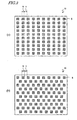
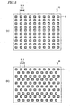
- the planar shape of the flow reducing members 5 may be either circular as shown in FIGS. 2(a) and 2(b) or rectangular as shown in FIGS. 3(a) and 3(b) , or may even be any of various other shapes (e.g., a rectangular polygonal shape).
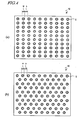
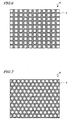
- the flow reducing members 5 may also have a circular ringlike planar shape as shown in FIGS. 4(a) and 4(b) or a polygonal ringlike planar shape as shown in FIGS. 5(a) and 5(b) .
- the flow reducing members 5 are typically made of a resin.
- preferred materials for the flow reducing members 5 include thermosetting resins such as urethane acrylate, acrylic, epoxy, and phenoxy resins, elastomers, and silicon rubbers.
- the flow reducing members 5 may be formed by depositing and patterning any of these resins on the decoration layer 2 by a printing process, for example. Naturally, the flow reducing members 5 do not have to be formed by a printing process. Alternatively, the flow reducing members 5 may also be formed by a dry film process that is often adopted in an IC manufacturing process or by putting the flow reducing members into the adhesive in advance and then distributing those members when the adhesive layer 4 is formed.
- the flow reducing members 5 are at least as hard as the decoration layer 2, then level differences will be created on the respective surfaces of the decoration layer 2 and the base member 1 when the decorative sheet 10 is attached to the formed product 21 as shown in FIG. 8 .
- a regular rugged pattern corresponding to the arrangement pattern of the flow reducing members 5, can be formed on the surface of the decorated formed product (i.e., on the outer surface of the decorative sheet 10).
- a rugged pattern has been formed on the surface of the decorated formed product, even if uneven gloss were produced due to non-uniform distribution of the adhesive, that unevenness would be much less sensible.
- a rugged pattern is recognized as a dimple pattern, its decorative effect would make the product's appearance even more attractive and impressive for potential buyers.
- the flow reducing members 5 preferably have a recess 5a on their surface in contact with the adhesive layer 4. If the surface of the flow reducing members 5 has such a shape, the adhesive will be retained in the recess 5a and the flow of the adhesive layer 4 can be reduced highly effectively.
- the thickness B of the thinnest portion of the flow reducing member 5 is preferably two-thirds or less of the thickness A of the thickest portion thereof.
- the flow reducing member 5 with the recess 5a may be formed by a screen printing process, for example.
- the decoration layer 2 does not have to be a single layer as shown in the drawings but may include multiple layers. Also, the decoration layer 2 may include not only an ink layer 2a but also a metal layer 2b as shown in FIG. 11 . If the decoration layer 2 includes a metal layer 2b, the decorative sheet 10 can have a metallic color, which gives the product a great-looking metallic appearance, due to the metallic gloss of the metal layer 2b.
- the metal layer 2b may be made of tin, aluminum, gold, copper, zinc, silver, indium or an alloy thereof.
- the decoration layer 2 may consist essentially of the metal layer 2b without the ink layer 2a.
- the metal layer 2b may be formed by an evaporation process, for example. Specifically, the metal layer 2b may be formed by evaporating a metal directly on the base member 1 (or on the ink layer 2a). Alternatively, a metal may be evaporated on a carrier film provided separately and then the stack may be bonded onto the base member 1 (or the ink layer 2a) to form the metal layer 2b.
- the present invention is even more effective in a situation where the decorative sheet 10 includes a metal layer 2b .
- the glass transition temperature of the material of the base member 1 is typically higher than the melting point of the material of the adhesive layer 4.
- the adhesive would have so high flowability as to be distributed unevenly and diminish the beauty of its appearance easily when the decorative sheet 110 is heated and softened.
- the melting point of material of the adhesive layer 4 is much lower than the glass transition temperature of the material of the base member 1 by 30 °C or more, for example, fine appearance without gloss unevenness is still realized.
- FIG. 12 schematically illustrates a vacuum forming system 100 for use to make a decorated formed product.
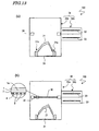
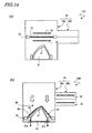
- FIGS. 13 through 15 are cross-sectional views schematically illustrating respective processing steps of the manufacturing process.
- the vacuum forming system 100 shown in FIG. 12 includes a gripping frame 30 to grip a decorative sheet 10 thereon, a supporting stage 31 for supporting a formed product thereon, a heater (such as a far-infrared heater) 33 for heating the decorative sheet 10, and a vacuum vessel 34 that stores all of these members.
- a gripping frame 30 to grip a decorative sheet 10 thereon
- a supporting stage 31 for supporting a formed product thereon
- a heater such as a far-infrared heater
- the vacuum vessel 34 consists of a main vessel 34a that stores the gripping frame 30 and the supporting stage 31, and a sub-vessel 34b that stores the heater 33. When the decorative sheet 10 is heated, the heater 33 is introduced into the main vessel 34a.
- the supporting stage 31 has a plurality of openings 31a, through which the air inside the main vessel 34a can be exhausted.
- a mechanism for introducing a gas from outside of this system into the main vessel 34a e.g., a hose connected to an external pump is also provided for the main vessel 34a.
- a decorated formed product may be made in the following manner, for example.
- a formed product 21 is provided and mounted on the supporting stage 31.
- the formed product 21 may be made of a resin material, a metallic material or any other suitable material by a known technique.
- the formed product 21 may be made of a resin material by an injection molding process.
- a decorative sheet 10 is provided and fixed onto the gripping frame 30.
- the decorative sheet 10 includes flow reducing members 5 in its adhesive layer 4.
- the decorative sheet 10 is heated with the heater 33 , thereby softening the decorative sheet 10.
- the decorative sheet 10 is preferably heated to a temperature of (T A -40) °C to (T A +20) °C, where T A is the load deflection temperature of the base member 1. If the decorative sheet 10 were heated to a temperature lower than (T A -40) °C,then the base member 1 would not be deformed easily and could crack when bonded to the formed product and formed into a desired shape or could even be non-formable at all. On the other hand, if the decorative sheet 10 were heated to a temperature higher than (T A + 20) °C, the sheet being heated could stretch too much to be formed into a desired shape.
- the decorative sheet 10 is heated to a temperature that is equal to or higher than the load deflection temperature T A of the base member 1 . Also, in this process step, the decorative sheet 10 is preferably heated to a temperature that is 20 to 30 °C higher than the lowest adhesion temperature of the adhesive layer 4 to ensure good adhesiveness for the adhesive layer 4.
- the load deflection temperature is measured under a prescribed load (of 0.45 MPa, for example) compliant with the ASTM D648 standard, which is a standard method of measuring a load deflection temperature that was set by the American Society for Testing and Materials. According to this standard, the temperature of a test piece is raised under a prescribed bending load and the temperature at which the deflection of the piece reaches a predetermined value is defined as the load deflection temperature.
- the decorative sheet 10 is brought down toward the formed product 21 and then the pressure in the space 35 between the decorative sheet 10 and the formed product 21 is reduced, thereby bonding the decorative sheet 10 onto the formed product 21 as shown in FIG. 15(a) . If the pressure in the space 35 between the decorative sheet 10 and the formed product 21 is reduced, then the decorative sheet 10 will be pressed against the formed product 21 with uniform pressure. As a result, the sheet 10 can be bonded to the product 21 effectively.
- the space 36 over the decorative sheet 10 is also pressurized, thereby making an even bigger pressure difference. Consequently, the decorative sheet 10 can be bonded even more quickly.
- the pressure in the space 35 may be reduced by exhausting the air in the space 35 through the openings 31a of the supporting stage 31 using a vacuum pump, for example.
- the pressure in the space 36 may be increased by supplying compressed air thereto using a compressor, for example.
- this process step the decorative sheet 10 is stretched and formed so as to fit the surface shape of the formed product 21 closely. If the decorative sheet 10 were too thin, then the beauty of its appearance would diminish. That is why this process step is preferably carried out such that the thickness of the decorative sheet 10 bonded becomes at least 0.4 times as large as, more preferably 0.5 or more times as large as, the original thickness.
- an excessive portion 10' of the decorative sheet 10 is trimmed with a rotating blade or any other cutter, and then the formed product 21 is removed from the supporting stage 30, thereby completing a formed product 20 with a decorated surface as shown in FIG. 15(c) .
- the decorative sheet 10 of this preferred embodiment includes flow reducing members 5 for reducing the flow of the adhesive layer 4. That is why even if the base member 1 shrinks in any of this series of process steps, the flow of the adhesive layer 4 due to the shrinkage can be virtually blocked. For that reason, the adhesive is not easily raised locally unlike the adhesive shown in FIG. 21(c) . Thus, in the decorative sheet 10, the adhesive is rarely distributed unevenly, and therefore, the string of uneven gloss can be virtually eliminated.
- a formed product can be decorated without diminishing the beauty of its appearance.
- the decorative sheet 10 can be used effectively to decorate a formed product with significant ruggedness, e.g., to decorate a deep-drawn formed product.
- FIGS. 16(a) and 16(b) illustrate an example of a deep-drawn formed product.
- the motorcycle fender 22 shown in FIGS. 16(a) and 16(b) has a shape with a large D/L ratio (which will be referred to herein as a "draw ratio" and), which is the ratio of the draw depth D to the draw diameter L (i.e., the width of a cross section of a formed product in the latitudinal direction). That is to say, the fender 22 has a deep-drawn shape.
- the decorative sheet 10 By using the decorative sheet 10, the diminution in the beauty of appearance due to the uneven distribution of the adhesive can be minimized, and therefore, even a formed product with a relatively large draw diameter L and a rather high draw ratio D/L can also be decorated effectively.
- a formed product of which the draw diameter L and draw depth D satisfy L ⁇ 100 mm and D/L ⁇ 1/3, is decorated, the beauty of its appearance diminishes significantly.
- the decorative sheet 10 of this preferred embodiment even a formed product with such a shape can also be decorated effectively without diminishing the beauty of its appearance.
- a formed product decorated with the decorative sheet 10 of this preferred embodiment can be used effectively as an interior or exterior member for a motor vehicle or as an exterior member for a consumer electronic appliance.
- the formed product can be used effectively as the tank housing 51, the front fender 52 or the tail cowl 53 of a motorcycle 50 as shown in FIG. 17 .
- the "motor vehicle” broadly refers to a self-propelled vehicle or machine that is used to transport passengers or goods or to transfer an object. Examples of motor vehicles include passenger cars, motorcycles, buses, trucks, tractors, airplanes, motorboats, and civil engineering vehicles.
- the motor vehicles include not only vehicles equipped with an internal combustion engine such as a gasoline engine but also those equipped with an electric motor.
- the decoration layer 2 is protected by the base member 1 and can maintain fine appearance for a long time.
- the formed product decorated with the decorative sheet 10 can be used outdoors particularly effectively in ships, outboard engines, water vehicles, all terrain vehicles (ATVs), snowmobiles, two wheelers, and golf cars.
- the present inventors actually made a decorated formed product using the decorative sheet 10 of this preferred embodiment and evaluated its appearance. The results of the evaluation will be described below.
- the flow reducing members were formed by a printing process.
- a formed product was decorated within a vacuum forming system with a decorative sheet obtained in this manner. As a result, fine appearance was realized without producing strings of uneven gloss.
- a decorative sheet was made as in the first specific example described above except that the flow reducing members had a diameter of 5 mm and a thickness of 5 ⁇ m and were arranged at an interval of 5 mm.
- a formed product was decorated within a vacuum forming system with a decorative sheet obtained in this manner. As a result, as in the first specific example just described, fine appearance was realized without producing strings of uneven gloss.
- a decorative sheet was made as in the first specific example described above except that the adhesive layer was deposited to a thickness of 100 ⁇ m.
- a formed product was decorated within a vacuum forming system with a decorative sheet obtained in this manner. As a result, as in the first specific example just described, fine appearance was realized without producing strings of uneven gloss.
- a decorative sheet was made as in the first specific example described above except that the flow reducing members were arranged in a ring pattern with an outside diameter of 4 mm and an inside diameter of 3.5 mm.
- a formed product was decorated within a vacuum forming system with a decorative sheet obtained in this manner. As a result, fine appearance was also realized without producing strings of uneven gloss.
- the appearance realized by this specific example was superior to that realized by the first specific example.
- a formed product was decorated within a vacuum forming system with a decorative sheet obtained in this manner. As a result, strings of uneven gloss were produced as shown in FIG. 20 to ruin its fine appearance.
- the present invention provides a decorative sheet that can decorate a formed product without diminishing the beauty of its appearance.
- the appearance of a formed product decorated with the decorative sheet of the present invention is so fine that the product can be used effectively as an exterior or interior member for any of various motor vehicles or as an exterior member for any of numerous consumer electronic appliances.
Landscapes
- Chemical & Material Sciences (AREA)
- Organic Chemistry (AREA)
- Engineering & Computer Science (AREA)
- Mechanical Engineering (AREA)
- Laminated Bodies (AREA)
- Vehicle Interior And Exterior Ornaments, Soundproofing, And Insulation (AREA)
Claims (16)
- Dekorfolie zur Verwendung, um ein geformtes Erzeugnis zu dekorieren, wobei die Folie aufweist:eine Dekorschicht;ein Basisteil, das die Dekorschicht trägt;eine Haftschicht zum Anhaften der Dekorschicht und des Basisteils auf dem geformten Erzeugnis; gekennzeichnet durchein fließreduzierendes Teil zum Reduzieren des Fließens der Haftschicht, wobei das fließreduzierende Teil in der Haftschicht vorgesehen ist und aus einem Material mit einem höheren Schmelzpunkt als derjenige von einem Material der Haftschicht hergestellt ist.
- Dekorfolie nach Anspruch 1, wobei das fließreduzierende Teil auf der Dekorschicht befestigt ist.
- Dekorfolie nach Anspruch 2, wobei die Haftschicht angeordnet ist, um die Dekorschicht und das fließreduzierende Teil, das auf der Dekorschicht befestigt ist, abzudecken.
- Dekorfolie nach einem der Ansprüche 1 bis 3, wobei der Schmelzpunkt des Materials des fließreduzierenden Teils um zumindest 20° C höher als der des Materials der Haftschicht ist.
- Dekorfolie nach einem der Ansprüche 1 bis 4, wobei die Elastizität des Materials des fließreduzierenden Teils zweimal so hoch wie die des Materials der Haftschicht bei 80" C ist.
- Dekorfolie nach einem der Ansprüche 1 bis 5, wobei das fließreduzierende Teil eine Aussparung an seiner Oberfläche hat, die mit der Haftschicht in Kontakt ist.
- Dekorfolie nach Anspruch 6, wobei der dünnste Abschnitt des fließreduzierenden Teils mit der Aussparung höchstens zwei Drittel so dick wie der dickste Abschnitt derselben ist,
- Dekorfolie nach einem der Ansprüche 1 bis 7, die eine Mehrzahl von fließreduzierenden Teilen aufweist.
- Dekorfolie nach Anspruch 9, wobei die fließreduzierenden Teile in regelmäßigen Abständen angeordnet sind.
- Dekorfolie nach einem der Ansprüche 1 bis 9, wobei der Schmelzpunkt des Materials der Haftschicht um mindestens 30° C niedriger als die Glasumwandlungstemperatur des Materials des Basisteils ist.
- Dekorfolie nach einem der Ansprüche 1 bis 10, wobei das Material des Basisteils Harz ist.
- Dekorfolie nach Anspruch 11, wobei das Harz ein thermoplastisches Harz ist.
- Dekoriertes, gebildetes Erzeugnis, aufweisend: ein gebildetes Erzeugnis; und die Dekorfolie nach einem der Ansprüche 1 bis 12, die mit der Oberfläche des gebildeten Erzeugnisses haftverbunden ist.
- Dekoriertes, geformtes Erzeugnis nach Anspruch 13, wobei das geformte Erzeugnis durch ein Tiefziehverfahren gebildet worden ist und solch eine Form hat, dass ein Ziehdurchmesser L und eine Ziehtiefe D den Bedingungen L ≧ 100 mm und D/L ≧ 1/3 genügt.
- Dekoriertes, geformtes Erzeugnis nach Anspruch 13 oder 14, wobei eine äußere Oberfläche der Dekorfolie, haftverbunden mit der Oberfläche des gebildeten Erzeugnisses, ein Rauheit hat, die einem Anordnungsmuster der fließreduzierenden Teile entspricht.
- Motorfahrzeug als das dekorierte, geformte Erzeugnis nach einem der Ansprüche 13 bis 15.
Applications Claiming Priority (2)
| Application Number | Priority Date | Filing Date | Title |
|---|---|---|---|
| JP2005264892 | 2005-09-13 | ||
| PCT/JP2006/317477 WO2007032223A1 (ja) | 2005-09-13 | 2006-09-04 | 装飾用シート、加飾成形品および自動車両 |
Publications (3)
| Publication Number | Publication Date |
|---|---|
| EP1829708A1 EP1829708A1 (de) | 2007-09-05 |
| EP1829708A4 EP1829708A4 (de) | 2008-03-12 |
| EP1829708B1 true EP1829708B1 (de) | 2009-04-15 |
Family
ID=37864822
Family Applications (1)
| Application Number | Title | Priority Date | Filing Date |
|---|---|---|---|
| EP06797400A Not-in-force EP1829708B1 (de) | 2005-09-13 | 2006-09-04 | Dekorfolie, dekorierter geformter artikel und motorfahrzeug |
Country Status (8)
| Country | Link |
|---|---|
| US (1) | US20090136691A1 (de) |
| EP (1) | EP1829708B1 (de) |
| JP (1) | JP4448538B2 (de) |
| CN (1) | CN101068687B (de) |
| AT (1) | ATE428577T1 (de) |
| DE (1) | DE602006006285D1 (de) |
| ES (1) | ES2324117T3 (de) |
| WO (1) | WO2007032223A1 (de) |
Families Citing this family (11)
| Publication number | Priority date | Publication date | Assignee | Title |
|---|---|---|---|---|
| DE102007058715A1 (de) * | 2007-12-06 | 2008-06-26 | Daimler Ag | Flächiges Dekorelement, insbesondere für einen Innenraum eines Kraftfahrzeugs sowie Verfahren zur dessen Herstellung |
| ITMI20130657A1 (it) * | 2013-04-22 | 2014-10-23 | Chiara Altruda | Realizzazione di un ornamento in materiale plastico trasparente |
| JP6726167B2 (ja) * | 2014-07-10 | 2020-07-22 | コーニング インコーポレイテッド | 冷間成形ガラスアップリケ |
| US20160271467A1 (en) * | 2015-01-19 | 2016-09-22 | Jbd Holdings Inc. | Texturized golf grip surfaces |
| CN108430861B (zh) * | 2015-12-28 | 2021-01-01 | 本田技研工业株式会社 | 鞍乘型车辆的挡泥部件 |
| WO2017141556A1 (ja) * | 2016-02-16 | 2017-08-24 | 山本印刷株式会社 | 加飾樹脂シートを備えた成形品とその製造方法 |
| ES2646912B2 (es) * | 2016-06-15 | 2018-05-03 | Juan AYELO VALIENTE | Soporte decorativo o publicitario para engalanamiento de exteriores en fiestas y eventos y procedimiento para su ejecución |
| ES2639113B2 (es) * | 2017-02-13 | 2018-03-08 | Juan AYELO VALIENTE | Mejoras en soporte decorativo o publicitario para engalanamiento de exteriores en fiestas y eventos y procedimiento para su ejecución |
| JP6630380B2 (ja) * | 2018-01-31 | 2020-01-15 | 本田技研工業株式会社 | 車両用内装材 |
| US11513262B2 (en) * | 2018-03-09 | 2022-11-29 | Konica Minolta, Inc. | Method for manufacturing structure |
| CN112634746A (zh) * | 2020-12-06 | 2021-04-09 | 江阴道达汽车饰件有限公司 | 一种高透亮彩色金属光泽字牌及其生产工艺 |
Family Cites Families (44)
| Publication number | Priority date | Publication date | Assignee | Title |
|---|---|---|---|---|
| US4012552A (en) * | 1975-03-10 | 1977-03-15 | Dennison Manufacturing Company | Decorative metal film heat transfer decalcomania |
| US4369222A (en) * | 1978-12-22 | 1983-01-18 | Monsanto Company | Metal-thermoplastic-metal laminates |
| US4296155A (en) * | 1979-10-16 | 1981-10-20 | Madonia Ciro N | Overcoated decorative moulding |
| US4475975A (en) * | 1980-12-19 | 1984-10-09 | General Motors Corporation | Decorating coated aluminum for extrusion encapsulation |
| US4404237A (en) * | 1980-12-29 | 1983-09-13 | General Electric Company | Fabrication of electrical conductor by replacement of metallic powder in polymer with more noble metal |
| JPS58197011A (ja) * | 1982-05-12 | 1983-11-16 | Honda Motor Co Ltd | 表皮成形材の製造法並にその製造装置 |
| US4520053A (en) * | 1983-08-10 | 1985-05-28 | Minnesota Mining And Manufacturing Company | Layered composite for applying graphics having areas or both mirror-like metal and patterned appearance |
| JPS60115281U (ja) * | 1984-01-09 | 1985-08-03 | 本田技研工業株式会社 | 車両の装飾用マ−ク |
| JPS60166500A (ja) * | 1984-02-10 | 1985-08-29 | 豊田合成株式会社 | 装飾部材 |
| JPS60242040A (ja) * | 1984-05-16 | 1985-12-02 | Mitsubishi Yuka Badische Kk | 緩衝性積層材の製造方法 |
| US4810540A (en) * | 1986-10-28 | 1989-03-07 | Rexham Corporation | Decorative sheet material simulating the appearance of a base coat/clear coat paint finish |
| JPH01175918U (de) * | 1988-05-26 | 1989-12-14 | ||
| US5055346A (en) * | 1988-08-30 | 1991-10-08 | Frank Rohrbacher | Thermoplastic acrylic polymer coated composite structure |
| US5178928A (en) * | 1988-09-22 | 1993-01-12 | Dai Nippon Insatsu Kabushiki Kaisha | Decorative materials |
| JPH0295893A (ja) * | 1988-09-30 | 1990-04-06 | Nissha Printing Co Ltd | 金属光沢模様転写材 |
| US4877657A (en) * | 1989-02-06 | 1989-10-31 | The D.L. Auld Company | Decorative trim strip with enhanced depth of vision |
| US4918800A (en) * | 1989-04-03 | 1990-04-24 | Eastman Kodak Company | Continuous method for making decorative sheet materials |
| JPH04126691A (ja) * | 1990-09-18 | 1992-04-27 | Honda Motor Co Ltd | 装飾シール貼着方法 |
| JPH04135837A (ja) * | 1990-09-28 | 1992-05-11 | Kanbou Create Kk | 装飾用表面材及びその製造方法 |
| JP3264543B2 (ja) * | 1993-03-04 | 2002-03-11 | 大日本印刷株式会社 | 高意匠化粧板及びその製造方法 |
| WO1995023688A1 (en) * | 1994-03-02 | 1995-09-08 | Hicks & Otis Prints, Incorporated | Vehicle part having weather sealed mirror finish decorative portion integral therewith |
| JPH0858052A (ja) * | 1994-08-23 | 1996-03-05 | Kanbou Create Kk | 装飾用表面材及びその製造方法と製造装置 |
| JPH0896351A (ja) * | 1994-09-20 | 1996-04-12 | Nitto Denko Corp | フレキシブル磁気記録ディスク接着用両面テープおよびそれを用いてなるフロッピーディスク |
| US5928767A (en) * | 1995-06-07 | 1999-07-27 | Dexter Corporation | Conductive film composite |
| ZA964731B (en) * | 1995-06-07 | 1997-01-07 | Avery Dennison Corp A Legal Bo | Extrusion coating process for making protective and decorative films |
| JP3017107B2 (ja) * | 1996-10-30 | 2000-03-06 | 大日本印刷株式会社 | 装飾シート及び装飾成形品並びに成形同時加飾方法 |
| US5869168A (en) * | 1997-01-10 | 1999-02-09 | Mahn, Jr.; John | Reflective heat activated transfer |
| DE19721058A1 (de) * | 1997-05-20 | 1998-11-26 | Giesecke & Devrient Gmbh | Spritzgußkarte mit Dekorschicht |
| DE19812880A1 (de) * | 1998-03-24 | 1999-09-30 | Bayer Ag | Formteil und flexible Folie mit geschützter Leiterbahn und Verfahren zu ihrer Herstellung |
| US6180207B1 (en) * | 1998-08-31 | 2001-01-30 | Patent Holding Company | Foil-covered automatic interior plastic part having a decorative preform and method of making same |
| US5931522A (en) * | 1998-08-27 | 1999-08-03 | Roskey; Timothy Allen | Magnetic motor vehicle body protection apparatus and method of use of the same |
| DE69913917T2 (de) * | 1998-10-30 | 2004-10-28 | Toyoda Gosei Co., Ltd. | Lenkrad |
| US6458464B1 (en) * | 1998-12-28 | 2002-10-01 | 3M Innovative Properties Company | Decorative sheet |
| JP2000204328A (ja) * | 1999-01-18 | 2000-07-25 | Teraoka Seisakusho:Kk | 反転印字装置用無支持体両面テ―プ |
| JP2000344158A (ja) * | 1999-06-07 | 2000-12-12 | Kansai Paint Co Ltd | 自動車車体 |
| US7060351B2 (en) * | 2000-04-24 | 2006-06-13 | Avery Dennison Corporation | Adhesive article with improved air egress |
| US6604834B2 (en) * | 2000-07-10 | 2003-08-12 | Blake H. Kalana | Electroluminescent surface illuminator device |
| FI20002038L (fi) * | 2000-09-15 | 2002-03-16 | Nokia Mobile Phones Ltd | Koristeltu ruiskupuristettu tuote ja menetelmä sen valmistamiseksi |
| US6491782B1 (en) * | 2000-11-02 | 2002-12-10 | Dennis Jaynes | Method of producing foil laminate with double-sided printing |
| US6803110B2 (en) * | 2001-01-22 | 2004-10-12 | Formica Corporation | Decorative laminate assembly and method for producing same |
| US6548128B2 (en) * | 2001-03-28 | 2003-04-15 | The Auld Company | Decorative emblems having an embedded image or design with an enhanced depth of vision and method of making same |
| JP2002319188A (ja) * | 2001-04-20 | 2002-10-31 | Ricoh Co Ltd | 貼合わせ型光情報記録媒体及びその基板形状 |
| US6677065B2 (en) * | 2001-11-08 | 2004-01-13 | Douglas Corporation | Pad printing of recessed surfaces for automobile emblems |
| JP4291676B2 (ja) * | 2003-11-26 | 2009-07-08 | ヤマハ発動機株式会社 | 装飾用シート、それを備えた成形品、自動車両、および成形品の製造方法 |
-
2006
- 2006-09-04 DE DE602006006285T patent/DE602006006285D1/de active Active
- 2006-09-04 CN CN2006800013024A patent/CN101068687B/zh not_active Expired - Fee Related
- 2006-09-04 ES ES06797400T patent/ES2324117T3/es active Active
- 2006-09-04 JP JP2007514194A patent/JP4448538B2/ja not_active Expired - Fee Related
- 2006-09-04 EP EP06797400A patent/EP1829708B1/de not_active Not-in-force
- 2006-09-04 WO PCT/JP2006/317477 patent/WO2007032223A1/ja not_active Ceased
- 2006-09-04 AT AT06797400T patent/ATE428577T1/de not_active IP Right Cessation
- 2006-09-04 US US11/718,646 patent/US20090136691A1/en not_active Abandoned
Also Published As
| Publication number | Publication date |
|---|---|
| DE602006006285D1 (de) | 2009-05-28 |
| EP1829708A1 (de) | 2007-09-05 |
| CN101068687A (zh) | 2007-11-07 |
| ATE428577T1 (de) | 2009-05-15 |
| JP4448538B2 (ja) | 2010-04-14 |
| WO2007032223A1 (ja) | 2007-03-22 |
| ES2324117T3 (es) | 2009-07-30 |
| EP1829708A4 (de) | 2008-03-12 |
| US20090136691A1 (en) | 2009-05-28 |
| JPWO2007032223A1 (ja) | 2009-03-19 |
| CN101068687B (zh) | 2010-07-14 |
Similar Documents
| Publication | Publication Date | Title |
|---|---|---|
| EP1829708B1 (de) | Dekorfolie, dekorierter geformter artikel und motorfahrzeug | |
| US6132662A (en) | Foil-covered plastic part and method of making same | |
| US8080124B2 (en) | Production method of a molded article | |
| JP4291676B2 (ja) | 装飾用シート、それを備えた成形品、自動車両、および成形品の製造方法 | |
| US5589022A (en) | Method of manufacturing emblem of thermoplastic synthetic resin sheet | |
| US6443531B1 (en) | Method for manufacturing a wheel cover | |
| EP1911566A1 (de) | Verfahren zur herstellung von formteilen und kraftfahrzeugen | |
| EP1864794B1 (de) | Dekorfolie, hergestelltes Produkt und Transportvorrichtung | |
| US9908309B2 (en) | Method of application of a decoration film | |
| JP2004181722A (ja) | 樹脂成形品の製造方法 | |
| EP2025728A1 (de) | Dekorfolie, hergestelltes Produkt und Fahrzeug | |
| US20060127646A1 (en) | Laminated decorative strip and method for producing a laminated decorative strip | |
| JP4785157B2 (ja) | 被転写体のステアリングホイールに木目模様を転写する転写方法と転写用シート | |
| US20070218240A1 (en) | Laser sculptured three-dimensional carbon fiber pattern sticker | |
| JP4137098B2 (ja) | キートップ板及びその製造方法 | |
| JP2024131820A (ja) | 車両用外装部品、および車両用外装部品の製造方法 | |
| JP2005353608A (ja) | キートップ板 |
Legal Events
| Date | Code | Title | Description |
|---|---|---|---|
| PUAI | Public reference made under article 153(3) epc to a published international application that has entered the european phase |
Free format text: ORIGINAL CODE: 0009012 |
|
| 17P | Request for examination filed |
Effective date: 20070503 |
|
| AK | Designated contracting states |
Kind code of ref document: A1 Designated state(s): AT BE BG CH CY CZ DE DK EE ES FI FR GB GR HU IE IS IT LI LT LU LV MC NL PL PT RO SE SI SK TR |
|
| AX | Request for extension of the european patent |
Extension state: AL BA HR MK YU |
|
| A4 | Supplementary search report drawn up and despatched |
Effective date: 20080213 |
|
| RIC1 | Information provided on ipc code assigned before grant |
Ipc: B60R 13/00 20060101ALI20080207BHEP Ipc: B44C 3/02 20060101ALI20080207BHEP Ipc: B44C 3/12 20060101ALI20080207BHEP Ipc: B44C 1/10 20060101AFI20080207BHEP Ipc: C09J 7/02 20060101ALI20080207BHEP Ipc: B62J 39/00 20060101ALI20080207BHEP Ipc: B32B 33/00 20060101ALI20080207BHEP |
|
| DAX | Request for extension of the european patent (deleted) | ||
| GRAP | Despatch of communication of intention to grant a patent |
Free format text: ORIGINAL CODE: EPIDOSNIGR1 |
|
| GRAS | Grant fee paid |
Free format text: ORIGINAL CODE: EPIDOSNIGR3 |
|
| GRAA | (expected) grant |
Free format text: ORIGINAL CODE: 0009210 |
|
| AK | Designated contracting states |
Kind code of ref document: B1 Designated state(s): AT BE BG CH CY CZ DE DK EE ES FI FR GB GR HU IE IS IT LI LT LU LV MC NL PL PT RO SE SI SK TR |
|
| REG | Reference to a national code |
Ref country code: GB Ref legal event code: FG4D Ref country code: CH Ref legal event code: EP |
|
| REG | Reference to a national code |
Ref country code: IE Ref legal event code: FG4D |
|
| REF | Corresponds to: |
Ref document number: 602006006285 Country of ref document: DE Date of ref document: 20090528 Kind code of ref document: P |
|
| REG | Reference to a national code |
Ref country code: ES Ref legal event code: FG2A Ref document number: 2324117 Country of ref document: ES Kind code of ref document: T3 |
|
| NLV1 | Nl: lapsed or annulled due to failure to fulfill the requirements of art. 29p and 29m of the patents act | ||
| PG25 | Lapsed in a contracting state [announced via postgrant information from national office to epo] |
Ref country code: PT Free format text: LAPSE BECAUSE OF FAILURE TO SUBMIT A TRANSLATION OF THE DESCRIPTION OR TO PAY THE FEE WITHIN THE PRESCRIBED TIME-LIMIT Effective date: 20090915 Ref country code: AT Free format text: LAPSE BECAUSE OF FAILURE TO SUBMIT A TRANSLATION OF THE DESCRIPTION OR TO PAY THE FEE WITHIN THE PRESCRIBED TIME-LIMIT Effective date: 20090415 Ref country code: LT Free format text: LAPSE BECAUSE OF FAILURE TO SUBMIT A TRANSLATION OF THE DESCRIPTION OR TO PAY THE FEE WITHIN THE PRESCRIBED TIME-LIMIT Effective date: 20090415 Ref country code: FI Free format text: LAPSE BECAUSE OF FAILURE TO SUBMIT A TRANSLATION OF THE DESCRIPTION OR TO PAY THE FEE WITHIN THE PRESCRIBED TIME-LIMIT Effective date: 20090415 |
|
| PG25 | Lapsed in a contracting state [announced via postgrant information from national office to epo] |
Ref country code: PL Free format text: LAPSE BECAUSE OF FAILURE TO SUBMIT A TRANSLATION OF THE DESCRIPTION OR TO PAY THE FEE WITHIN THE PRESCRIBED TIME-LIMIT Effective date: 20090415 Ref country code: IS Free format text: LAPSE BECAUSE OF FAILURE TO SUBMIT A TRANSLATION OF THE DESCRIPTION OR TO PAY THE FEE WITHIN THE PRESCRIBED TIME-LIMIT Effective date: 20090815 Ref country code: SI Free format text: LAPSE BECAUSE OF FAILURE TO SUBMIT A TRANSLATION OF THE DESCRIPTION OR TO PAY THE FEE WITHIN THE PRESCRIBED TIME-LIMIT Effective date: 20090415 Ref country code: LV Free format text: LAPSE BECAUSE OF FAILURE TO SUBMIT A TRANSLATION OF THE DESCRIPTION OR TO PAY THE FEE WITHIN THE PRESCRIBED TIME-LIMIT Effective date: 20090415 Ref country code: NL Free format text: LAPSE BECAUSE OF FAILURE TO SUBMIT A TRANSLATION OF THE DESCRIPTION OR TO PAY THE FEE WITHIN THE PRESCRIBED TIME-LIMIT Effective date: 20090415 Ref country code: SE Free format text: LAPSE BECAUSE OF FAILURE TO SUBMIT A TRANSLATION OF THE DESCRIPTION OR TO PAY THE FEE WITHIN THE PRESCRIBED TIME-LIMIT Effective date: 20090715 |
|
| PG25 | Lapsed in a contracting state [announced via postgrant information from national office to epo] |
Ref country code: EE Free format text: LAPSE BECAUSE OF FAILURE TO SUBMIT A TRANSLATION OF THE DESCRIPTION OR TO PAY THE FEE WITHIN THE PRESCRIBED TIME-LIMIT Effective date: 20090415 Ref country code: DK Free format text: LAPSE BECAUSE OF FAILURE TO SUBMIT A TRANSLATION OF THE DESCRIPTION OR TO PAY THE FEE WITHIN THE PRESCRIBED TIME-LIMIT Effective date: 20090415 Ref country code: RO Free format text: LAPSE BECAUSE OF FAILURE TO SUBMIT A TRANSLATION OF THE DESCRIPTION OR TO PAY THE FEE WITHIN THE PRESCRIBED TIME-LIMIT Effective date: 20090415 Ref country code: CZ Free format text: LAPSE BECAUSE OF FAILURE TO SUBMIT A TRANSLATION OF THE DESCRIPTION OR TO PAY THE FEE WITHIN THE PRESCRIBED TIME-LIMIT Effective date: 20090415 |
|
| PLBE | No opposition filed within time limit |
Free format text: ORIGINAL CODE: 0009261 |
|
| STAA | Information on the status of an ep patent application or granted ep patent |
Free format text: STATUS: NO OPPOSITION FILED WITHIN TIME LIMIT |
|
| PG25 | Lapsed in a contracting state [announced via postgrant information from national office to epo] |
Ref country code: SK Free format text: LAPSE BECAUSE OF FAILURE TO SUBMIT A TRANSLATION OF THE DESCRIPTION OR TO PAY THE FEE WITHIN THE PRESCRIBED TIME-LIMIT Effective date: 20090415 Ref country code: BE Free format text: LAPSE BECAUSE OF FAILURE TO SUBMIT A TRANSLATION OF THE DESCRIPTION OR TO PAY THE FEE WITHIN THE PRESCRIBED TIME-LIMIT Effective date: 20090415 |
|
| 26N | No opposition filed |
Effective date: 20100118 |
|
| PG25 | Lapsed in a contracting state [announced via postgrant information from national office to epo] |
Ref country code: BG Free format text: LAPSE BECAUSE OF FAILURE TO SUBMIT A TRANSLATION OF THE DESCRIPTION OR TO PAY THE FEE WITHIN THE PRESCRIBED TIME-LIMIT Effective date: 20090715 |
|
| PG25 | Lapsed in a contracting state [announced via postgrant information from national office to epo] |
Ref country code: MC Free format text: LAPSE BECAUSE OF NON-PAYMENT OF DUE FEES Effective date: 20090930 |
|
| REG | Reference to a national code |
Ref country code: IE Ref legal event code: MM4A |
|
| PG25 | Lapsed in a contracting state [announced via postgrant information from national office to epo] |
Ref country code: IE Free format text: LAPSE BECAUSE OF NON-PAYMENT OF DUE FEES Effective date: 20090904 |
|
| PG25 | Lapsed in a contracting state [announced via postgrant information from national office to epo] |
Ref country code: GR Free format text: LAPSE BECAUSE OF FAILURE TO SUBMIT A TRANSLATION OF THE DESCRIPTION OR TO PAY THE FEE WITHIN THE PRESCRIBED TIME-LIMIT Effective date: 20090716 |
|
| PG25 | Lapsed in a contracting state [announced via postgrant information from national office to epo] |
Ref country code: LU Free format text: LAPSE BECAUSE OF NON-PAYMENT OF DUE FEES Effective date: 20090904 |
|
| REG | Reference to a national code |
Ref country code: CH Ref legal event code: PL |
|
| PG25 | Lapsed in a contracting state [announced via postgrant information from national office to epo] |
Ref country code: HU Free format text: LAPSE BECAUSE OF FAILURE TO SUBMIT A TRANSLATION OF THE DESCRIPTION OR TO PAY THE FEE WITHIN THE PRESCRIBED TIME-LIMIT Effective date: 20091016 |
|
| PG25 | Lapsed in a contracting state [announced via postgrant information from national office to epo] |
Ref country code: CH Free format text: LAPSE BECAUSE OF NON-PAYMENT OF DUE FEES Effective date: 20100930 Ref country code: LI Free format text: LAPSE BECAUSE OF NON-PAYMENT OF DUE FEES Effective date: 20100930 |
|
| PG25 | Lapsed in a contracting state [announced via postgrant information from national office to epo] |
Ref country code: TR Free format text: LAPSE BECAUSE OF FAILURE TO SUBMIT A TRANSLATION OF THE DESCRIPTION OR TO PAY THE FEE WITHIN THE PRESCRIBED TIME-LIMIT Effective date: 20090415 |
|
| PG25 | Lapsed in a contracting state [announced via postgrant information from national office to epo] |
Ref country code: CY Free format text: LAPSE BECAUSE OF FAILURE TO SUBMIT A TRANSLATION OF THE DESCRIPTION OR TO PAY THE FEE WITHIN THE PRESCRIBED TIME-LIMIT Effective date: 20090415 |
|
| REG | Reference to a national code |
Ref country code: FR Ref legal event code: PLFP Year of fee payment: 10 |
|
| PGFP | Annual fee paid to national office [announced via postgrant information from national office to epo] |
Ref country code: FR Payment date: 20150626 Year of fee payment: 10 |
|
| PGFP | Annual fee paid to national office [announced via postgrant information from national office to epo] |
Ref country code: DE Payment date: 20150922 Year of fee payment: 10 Ref country code: ES Payment date: 20150928 Year of fee payment: 10 Ref country code: GB Payment date: 20150917 Year of fee payment: 10 |
|
| PGFP | Annual fee paid to national office [announced via postgrant information from national office to epo] |
Ref country code: IT Payment date: 20150924 Year of fee payment: 10 |
|
| REG | Reference to a national code |
Ref country code: DE Ref legal event code: R119 Ref document number: 602006006285 Country of ref document: DE |
|
| GBPC | Gb: european patent ceased through non-payment of renewal fee |
Effective date: 20160904 |
|
| REG | Reference to a national code |
Ref country code: FR Ref legal event code: ST Effective date: 20170531 |
|
| PG25 | Lapsed in a contracting state [announced via postgrant information from national office to epo] |
Ref country code: FR Free format text: LAPSE BECAUSE OF NON-PAYMENT OF DUE FEES Effective date: 20160930 Ref country code: DE Free format text: LAPSE BECAUSE OF NON-PAYMENT OF DUE FEES Effective date: 20170401 Ref country code: GB Free format text: LAPSE BECAUSE OF NON-PAYMENT OF DUE FEES Effective date: 20160904 |
|
| PG25 | Lapsed in a contracting state [announced via postgrant information from national office to epo] |
Ref country code: IT Free format text: LAPSE BECAUSE OF NON-PAYMENT OF DUE FEES Effective date: 20160904 |
|
| PG25 | Lapsed in a contracting state [announced via postgrant information from national office to epo] |
Ref country code: ES Free format text: LAPSE BECAUSE OF NON-PAYMENT OF DUE FEES Effective date: 20160905 |
|
| REG | Reference to a national code |
Ref country code: ES Ref legal event code: FD2A Effective date: 20181130 |