EP1843217A2 - Vorrichtung zur Messung einer Tonermenge und Bilderzeugungsvorrichtung mit der Messvorrichtung - Google Patents
Vorrichtung zur Messung einer Tonermenge und Bilderzeugungsvorrichtung mit der Messvorrichtung Download PDFInfo
- Publication number
- EP1843217A2 EP1843217A2 EP07075571A EP07075571A EP1843217A2 EP 1843217 A2 EP1843217 A2 EP 1843217A2 EP 07075571 A EP07075571 A EP 07075571A EP 07075571 A EP07075571 A EP 07075571A EP 1843217 A2 EP1843217 A2 EP 1843217A2
- Authority
- EP
- European Patent Office
- Prior art keywords
- light
- toner
- image carrier
- emitting element
- measuring apparatus
- Prior art date
- Legal status (The legal status is an assumption and is not a legal conclusion. Google has not performed a legal analysis and makes no representation as to the accuracy of the status listed.)
- Withdrawn
Links
- 238000005259 measurement Methods 0.000 claims description 47
- 238000000034 method Methods 0.000 claims description 38
- 230000008569 process Effects 0.000 claims description 37
- 230000008859 change Effects 0.000 claims description 35
- 238000001514 detection method Methods 0.000 claims description 9
- 238000012544 monitoring process Methods 0.000 claims description 5
- 230000003321 amplification Effects 0.000 claims 1
- 239000000284 extract Substances 0.000 claims 1
- 238000003199 nucleic acid amplification method Methods 0.000 claims 1
- 238000012546 transfer Methods 0.000 description 63
- 230000004044 response Effects 0.000 description 8
- 230000007423 decrease Effects 0.000 description 7
- 230000007613 environmental effect Effects 0.000 description 6
- 230000000694 effects Effects 0.000 description 5
- 230000006872 improvement Effects 0.000 description 4
- 238000012986 modification Methods 0.000 description 3
- 230000004048 modification Effects 0.000 description 3
- 239000003086 colorant Substances 0.000 description 2
- 230000009977 dual effect Effects 0.000 description 2
- 230000001678 irradiating effect Effects 0.000 description 2
- 230000003287 optical effect Effects 0.000 description 2
- 230000010287 polarization Effects 0.000 description 2
- 238000013459 approach Methods 0.000 description 1
- 238000006243 chemical reaction Methods 0.000 description 1
- 239000002131 composite material Substances 0.000 description 1
- 238000007796 conventional method Methods 0.000 description 1
- 238000012937 correction Methods 0.000 description 1
- 230000008030 elimination Effects 0.000 description 1
- 238000003379 elimination reaction Methods 0.000 description 1
- 230000006870 function Effects 0.000 description 1
- 230000007257 malfunction Effects 0.000 description 1
- 230000009467 reduction Effects 0.000 description 1
- 238000000926 separation method Methods 0.000 description 1
- 230000006641 stabilisation Effects 0.000 description 1
- 238000011105 stabilization Methods 0.000 description 1
Images


Classifications
-
- G—PHYSICS
- G03—PHOTOGRAPHY; CINEMATOGRAPHY; ANALOGOUS TECHNIQUES USING WAVES OTHER THAN OPTICAL WAVES; ELECTROGRAPHY; HOLOGRAPHY
- G03G—ELECTROGRAPHY; ELECTROPHOTOGRAPHY; MAGNETOGRAPHY
- G03G15/00—Apparatus for electrographic processes using a charge pattern
- G03G15/50—Machine control of apparatus for electrographic processes using a charge pattern, e.g. regulating differents parts of the machine, multimode copiers, microprocessor control
- G03G15/5062—Machine control of apparatus for electrographic processes using a charge pattern, e.g. regulating differents parts of the machine, multimode copiers, microprocessor control by measuring the characteristics of an image on the copy material
-
- G—PHYSICS
- G03—PHOTOGRAPHY; CINEMATOGRAPHY; ANALOGOUS TECHNIQUES USING WAVES OTHER THAN OPTICAL WAVES; ELECTROGRAPHY; HOLOGRAPHY
- G03G—ELECTROGRAPHY; ELECTROPHOTOGRAPHY; MAGNETOGRAPHY
- G03G15/00—Apparatus for electrographic processes using a charge pattern
- G03G15/01—Apparatus for electrographic processes using a charge pattern for producing multicoloured copies
- G03G15/0105—Details of unit
- G03G15/0131—Details of unit for transferring a pattern to a second base
-
- G—PHYSICS
- G03—PHOTOGRAPHY; CINEMATOGRAPHY; ANALOGOUS TECHNIQUES USING WAVES OTHER THAN OPTICAL WAVES; ELECTROGRAPHY; HOLOGRAPHY
- G03G—ELECTROGRAPHY; ELECTROPHOTOGRAPHY; MAGNETOGRAPHY
- G03G15/00—Apparatus for electrographic processes using a charge pattern
- G03G15/50—Machine control of apparatus for electrographic processes using a charge pattern, e.g. regulating differents parts of the machine, multimode copiers, microprocessor control
- G03G15/5033—Machine control of apparatus for electrographic processes using a charge pattern, e.g. regulating differents parts of the machine, multimode copiers, microprocessor control by measuring the photoconductor characteristics, e.g. temperature, or the characteristics of an image on the photoconductor
- G03G15/5041—Detecting a toner image, e.g. density, toner coverage, using a test patch
-
- G—PHYSICS
- G03—PHOTOGRAPHY; CINEMATOGRAPHY; ANALOGOUS TECHNIQUES USING WAVES OTHER THAN OPTICAL WAVES; ELECTROGRAPHY; HOLOGRAPHY
- G03G—ELECTROGRAPHY; ELECTROPHOTOGRAPHY; MAGNETOGRAPHY
- G03G15/00—Apparatus for electrographic processes using a charge pattern
- G03G15/50—Machine control of apparatus for electrographic processes using a charge pattern, e.g. regulating differents parts of the machine, multimode copiers, microprocessor control
- G03G15/5054—Machine control of apparatus for electrographic processes using a charge pattern, e.g. regulating differents parts of the machine, multimode copiers, microprocessor control by measuring the characteristics of an intermediate image carrying member or the characteristics of an image on an intermediate image carrying member, e.g. intermediate transfer belt or drum, conveyor belt
- G03G15/5058—Machine control of apparatus for electrographic processes using a charge pattern, e.g. regulating differents parts of the machine, multimode copiers, microprocessor control by measuring the characteristics of an intermediate image carrying member or the characteristics of an image on an intermediate image carrying member, e.g. intermediate transfer belt or drum, conveyor belt using a test patch
-
- G—PHYSICS
- G03—PHOTOGRAPHY; CINEMATOGRAPHY; ANALOGOUS TECHNIQUES USING WAVES OTHER THAN OPTICAL WAVES; ELECTROGRAPHY; HOLOGRAPHY
- G03G—ELECTROGRAPHY; ELECTROPHOTOGRAPHY; MAGNETOGRAPHY
- G03G2215/00—Apparatus for electrophotographic processes
- G03G2215/00025—Machine control, e.g. regulating different parts of the machine
- G03G2215/00029—Image density detection
- G03G2215/00033—Image density detection on recording member
- G03G2215/00037—Toner image detection
- G03G2215/00042—Optical detection
-
- G—PHYSICS
- G03—PHOTOGRAPHY; CINEMATOGRAPHY; ANALOGOUS TECHNIQUES USING WAVES OTHER THAN OPTICAL WAVES; ELECTROGRAPHY; HOLOGRAPHY
- G03G—ELECTROGRAPHY; ELECTROPHOTOGRAPHY; MAGNETOGRAPHY
- G03G2215/00—Apparatus for electrophotographic processes
- G03G2215/00025—Machine control, e.g. regulating different parts of the machine
- G03G2215/00029—Image density detection
- G03G2215/00059—Image density detection on intermediate image carrying member, e.g. transfer belt
-
- G—PHYSICS
- G03—PHOTOGRAPHY; CINEMATOGRAPHY; ANALOGOUS TECHNIQUES USING WAVES OTHER THAN OPTICAL WAVES; ELECTROGRAPHY; HOLOGRAPHY
- G03G—ELECTROGRAPHY; ELECTROPHOTOGRAPHY; MAGNETOGRAPHY
- G03G2215/00—Apparatus for electrophotographic processes
- G03G2215/00025—Machine control, e.g. regulating different parts of the machine
- G03G2215/00029—Image density detection
- G03G2215/00063—Colour
-
- G—PHYSICS
- G03—PHOTOGRAPHY; CINEMATOGRAPHY; ANALOGOUS TECHNIQUES USING WAVES OTHER THAN OPTICAL WAVES; ELECTROGRAPHY; HOLOGRAPHY
- G03G—ELECTROGRAPHY; ELECTROPHOTOGRAPHY; MAGNETOGRAPHY
- G03G2215/00—Apparatus for electrophotographic processes
- G03G2215/06—Developing structures, details
- G03G2215/0634—Developing device
Definitions
- the present invention relates to a toner quantity measuring apparatus which measures the quantity of toner adhering to an image carrier such as a photosensitive member and a transfer medium, and an image forming apparatus which comprises such a toner quantity measuring apparatus.
- an image forming apparatus of the electrophotographic type such as a printer, a copier machine and a facsimile machine, internally comprises a toner quantity measuring apparatus which measures the quantity of toner adhering to an image carrier such as a photosensitive member and a transfer medium.
- a toner quantity measuring apparatus is as described in Japanese Patent Application Unexamined Gazette No. 2000-29271 , for example.
- a toner quantity measuring apparatus described in this gazette (hereinafter "first conventional apparatus") has a light emitting element irradiating light toward an image carrier such as a photosensitive member and a reflection-side light receiving unit including a light receiving element. The light receiving element receives reflected light from the photosensitive member so that the quantity of toner on the photosensitive member is calculated based on the quantity of the received light (the quantity of the reflected light).
- a beam splitter splits the irradiated light at a predetermined ratio, whereby the irradiated light is partially extracted.
- Another light receiving element (of irradiation-side light receiving unit) detects the quantity of the extracted light, and the light emitting element is feedback-controlled in such a manner that the detection result stays at a reference value.
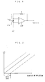
- Fig. 1 is a drawing of an electric structure of a conventional light receiving unit.
- an anode terminal of a light receiving element PS such as a photodiode
- a light receiving element PS is connected with a ground potential and a non-inversion input terminal of an operational amplifier OP which forms a current-voltage (I/V) conversion circuit.
- a cathode terminal of the light receiving element PS is connected with the non-inversion input terminal of the operational amplifier OP, and additionally, with an output terminal of the operational amplifier OP through a resistor R.
- the light receiving unit outputs a signal corresponding to the quantity of the reflected light.
- the circuitry of the light receiving unit is normally configured such that a detection signal having a characteristic as that denoted at the solid line in Fig. 2 is obtained.
- a characteristic as that denoted at the dotted line or the dotted-and-dashed line in Fig. 2 may be realized.
- a characteristic as that denoted at the dotted-and-dashed line in Fig. 2 will be considered.
- the circuit shown in Fig. 1 is operated by a dual power supply which uses a (+15V)-power source and a (-15V)-power source
- a negative voltage is outputted when the quantity of the reflected light is zero.
- a dual power supply requires a higher cost for a power source part
- a single power supply with only a (+15V)-power source is often used in an actual apparatus.
- a so-called dead zone where the output voltage level remains at zero without any change will be developed.
- a toner quantity on the high-density side may be to increase the quantity of the irradiated light from the light emitting element, and hence, the quantity of the reflected light.
- this merely shifts the problematic zone but fails to completely solve the problem since a similar problem will rise during measurement of the quantity of toner having an even higher density.
- it is possible to set the quantity of the irradiated light from the light emitting element only at one single light quantity. Hence, a toner quantity can be accurately measured only within a limited density range in the first conventional apparatus.
- a characteristic as that denoted at the dotted line in Fig. 2 leads to a situation that an output does not become zero even if the light emitting element is not irradiating light, which is known as outputting of a dark output. Due to this, even when the light emitting element irradiates light upon the photosensitive member and the quantity of the reflected light from the photosensitive member is detected, the detection result contains a dark output component. Adding to the difficulty, the dark output is relevant to characteristics such as a dark current of the light receiving unit and an offset of the operational amplifier, and therefore, changes in accordance with an environmental condition, such as a temperature around the apparatus, and a change with time of the components which form the apparatus. Thus, highly accurate measurement of a toner quantity is difficult.
- a conventional approach to these problems is to suppress the irregularity using an adjustment circuit which is disposed inside the apparatus.
- an adjustment circuit which is disposed inside the apparatus.
- such a structure has been met with a challenge that the light receiving unit has a complex circuit, a higher cost is required as repeated adjustment is necessary and even more highly accurate measurement is difficult because of other factors such as uneven adjustment.
- a light emitting element irradiates light toward a photosensitive member (image carrier), light reflected at the photosensitive member is split into p-polarized light and s-polarized light, and a p-polarized light receiving unit detects the quantity of the p-polarized light while an s-polarized light receiving unit detects the quantity of the s-polarized light.
- the quantity of toner on the photosensitive member is found based on a difference between these two light quantities.
- the second conventional apparatus units as that shown in Fig. 1 are used as the light receiving units, which results in similar problems to those with the first conventional apparatus described above. Further, measuring the quantity of the toner based on the difference between the two light quantities, the second conventional apparatus has another problem as described below. Owing to an environmental factor such as an ambient temperature and humidity, a change with time of the light emitting element, etc., the quantity of irradiated light upon the photosensitive member, a transfer image carrier or the like may sometimes change, and therefore, a toner quantity is wrongly detected because of the change in the quantity of irradiated light.
- an environmental factor such as an ambient temperature and humidity, a change with time of the light emitting element, etc.
- the quantity of irradiated light upon the photosensitive member, a transfer image carrier or the like may sometimes change, and therefore, a toner quantity is wrongly detected because of the change in the quantity of irradiated light.
- a principal object of the present invention is to provide a toner quantity measuring apparatus which allows highly accurate measurement of the quantity of toner which adheres on an image carrier such as a photosensitive member and a transfer medium.
- Another object of the present invention is to provide an image forming apparatus which creates an image with a stable density based on a result of measurement obtained by the toner quantity measuring apparatus.
- a predetermined output offset is applied to the output from a light receiving element.
- Toner quantity calculating means calculates the quantity of toner which adheres to an image carrier based on the output from the light receiving element. In this manner, with application of the output offset, it is possible to eliminate an influence of a dead zone without fail and output an output which corresponds to the quantity of the reflected light.
- irradiation amount adjusting means keeps a light emitting element turned off while a light quantity control signal to control the quantity of light irradiated by the light emitting element remains below a predetermined input offset. This allows to turn the light emitting element off without fail.
- reflection quantity detecting means detects light quantities of a first and a second light components which are different from each other and contained in reflected light from an image carrier
- toner quantity calculating means calculates a light quantity ratio between the light quantity of the first light component and the light quantity of the second light component which are detected by the reflection quantity detecting means, and calculates the quantity of toner adhering on the image carrier based on the light quantity ratio.
- toner quantity calculating means is structured so as to be able to execute, as a measurement process of measuring a toner quantity, a plurality of toner quantity detection processes which are different from each other, and selectively executes one of the plurality of toner quantity detection processes in accordance with the color of toner adhering on the image carrier.
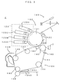
- Fig. 3 is a drawing of a preferred embodiment of an image forming apparatus according to the present invention.
- This image forming apparatus is an apparatus which overlays toner in four colors of yellow (Y), cyan (C), magenta (M) and black (K) one atop the other and creates a full-color image.
- a control unit (denoted generally at 6 in Fig. 4) receives an image signal from an external apparatus such as a host computer, an image corresponding to the image signal is created on a sheet S, such as a transfer paper, a copier paper and a transparency for an overhead projector, with the respective portions of an engine part E operating under the control of the control unit.
- the process unit 102 comprises the photosensitive member 121 which can rotate in the direction indicated by the arrow in Fig. 3.
- an electrifying roller 122 serving as electrifying means
- developers 123Y, 123C, 123M and 123K serving as developing means
- a cleaner blade 124 for the photosensitive member are disposed around the photosensitive member 121 and along the direction of rotations of the photosensitive member 121.
- an exposure unit 103 irradiates laser light L toward the outer circumferential surface of the photosensitive member 121 to form an electrostatic latent image thereon.
- the electrostatic latent image thus created is developed with toner by a developer part 123.
- the developer 123Y for yellow, the developer 123C for cyan, the developer 123M for magenta and the developer 123K for black are arranged as the developer part 123 in this order along the photosensitive member 121, according to this embodiment.
- the developers 123Y, 123C, 123M and 123K are each capable of freely abutting to and departing from the photosensitive member 121.
- one of the four developers 123Y, 123C, 123M and 123K selectively contacts the photosensitive member 121, supplies toner of a selected color to a surface of the photosensitive member 121 by means of an applied high voltage, and visualizes the electrostatic latent image on the photosensitive member 121.
- the toner image developed by the developer part 123 is primarily transferred, in a primary transfer area located between the black developer 123K and the cleaner blade 124 for the photosensitive member 121, onto an intermediate transfer belt 141 (image carrier) of a transfer unit 4. Further, as the cleaner blade 124 for the photosensitive member is disposed at a position ahead of the primary transfer area in a circumferential direction (which is the direction indicated at the arrow in Fig. 3), the toner still sticking to the outer circumferential surface of the photosensitive member 121 is scraped off.
- the transfer unit 104 comprises seven rollers 142 to 148, and the endless intermediate transfer belt 141 is spun across the six rollers 142 to 147 except for the secondary transfer roller 148.
- Toner images of the respective colors formed on the photosensitive member 121 are laid one atop the other on the intermediate transfer belt 141 thereby forming a color image, during which the sheet S unloaded from a cassette or a hand-feed tray travels to a secondary transfer area moving passed between an upper guide member 105U and a lower guide member 105D, whereby the color image is secondarily transferred onto the sheet S and the color image is obtained (color printing process).
- a belt cleaner 149 is disposed facing the roller 146, and after the secondary transfer, the belt cleaner 149 removes and cleans residual toner off the intermediate transfer belt 141. Further, there is a sensor 140 below the roller 143 for detection of a reference position of the intermediate transfer belt 141. This sensor serves as a vertical synchronization reader sensor for obtaining a synchronizing signal in a sub scanning direction which is approximately perpendicular to a main scanning direction, i.e., a vertical synchronizing signal.
- a main part 2 of a toner quantity measuring apparatus which measures the quantity of toner adhering on the intermediate transfer belt 141 is disposed facing the roller 143 across the intermediate transfer belt 141. Based on the quantity of toner adhering to the surface of the intermediate transfer belt 141 measured by this toner quantity measuring apparatus, a control unit 6 adjusts process conditions such as an electrifying bias and a developing bias and controls an image density.
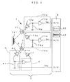
- Fig. 4 is a drawing showing a first preferred embodiment of the toner quantity measuring apparatus which is incorporated within the image forming apparatus shown in Fig. 3.
- This toner quantity measuring apparatus comprises a light emitting element 1 such as an LED which irradiates light toward the intermediate transfer belt 141.
- a polarizing beam splitter 3 for the purpose of adjusting the quantity of the irradiation, there are a polarizing beam splitter 3, an irradiation quantity monitoring light receiving unit 4 and an irradiation quantity adjusting unit 5.
- the polarizing beam splitter 3 is located between the light emitting element 1 and the intermediate transfer belt 141 as shown in Fig. 4, and splits into p-polarized light whose polarization direction is parallel to a surface of incidence of the irradiated light on the intermediate transfer belt 141 and s-polarized light whose polarization direction is perpendicular to the surface of incidence. While the p-polarized light as it is impinges upon the intermediate transfer belt 141, the s-polarized light enters the irradiation quantity monitoring light receiving unit 4 after leaving the polarizing beam splitter 3 so that a signal which is in proportion to the quantity of the irradiated light from the light receiving unit 4 is outputted to the irradiation quantity adjusting unit 5.
- the irradiation quantity adjusting unit 5 feedback-controls the light emitting element 1 based on a light quantity control signal S1c provided from the control unit 6 which comprises a CPU 61 and a memory 62 and controls the apparatus as a whole, whereby the quantity of the irradiated light from the light emitting element 1 illuminating the intermediate transfer belt 141 is adjusted to a value which corresponds to the light quantity control signal Slc.
- the control unit 6 which comprises a CPU 61 and a memory 62 and controls the apparatus as a whole, whereby the quantity of the irradiated light from the light emitting element 1 illuminating the intermediate transfer belt 141 is adjusted to a value which corresponds to the light quantity control signal Slc.
- this embodiment permits to change and adjust the quantity of irradiation in a wide range.
- an input offset voltage 41 is applied to the output side of a light receiving element 42 which is disposed to the irradiation quantity monitoring light receiving unit 4, and therefore, the light emitting element 1 is maintained turned off unless the light quantity control signal S1c exceeds a certain signal level.
- a light quantity characteristic is as indicated at the dotted line in Fig. 6. That is, as the light quantity control signal Slc(0) is supplied to the irradiation quantity adjusting unit 5 from the control unit 6, the light emitting element 1 turns off. The light emitting element 1 turns on when the signal level of the light quantity control signal Slc increases, and the quantity of the irradiated light upon the intermediate transfer belt 141 as well increases in approximate proportion to the signal level.
- the light quantity characteristic sometimes shifts parallel as indicated at the dotted-and-dashed line or the double-dotted-and-dotted-and-dashed line in Fig.
- the light emitting element 1 may stay turned on despite a turn-off instruction, namely, the light quantity control signal Slc(0) from the control unit 6.
- the light emitting element 1 turns on and p-polarized light is irradiated as irradiation toward the intermediate transfer belt 141
- the intermediate transfer belt 141 reflects the p-polarized light
- a reflection quantity detecting unit 7 detects the quantities of the p-polarized light and the s-polarized light among light components of the reflected light, and signals corresponding to the respective light quantities are outputted to the control unit 6.
- the reflection quantity detecting unit 7 comprises a polarized beam splitter 71 which is disposed on an optical path of the reflected light, a light receiving unit 70p which receives the p-polarized light which travels through the polarized beam splitter 71 and outputs a signal corresponding to the quantity of the p-polarized light, and a light receiving unit 70s which receives the s-polarized light split by the polarized beam splitter 71 and outputs a signal corresponding to the quantity of the s-polarized light.
- a light receiving element 72p receives the p-polarized light from the polarized beam splitter 71, and after the output from the light receiving element 72p is amplified by an amplifier circuit 73p, the light receiving unit 70p outputs the amplified signal as a signal which corresponds to the quantity of the p-polarized light.
- the light receiving unit 70s comprises a light receiving element 72s and an amplifier circuit 73s.
- output offset voltages 74p, 74s are applied respectively to the output side of the light receiving elements 72p, 72s, and output voltages Vp, Vs of signals supplied to the control unit 6 from the amplifier circuits 73p, 73s are offset to the positive side as shown in Fig. 7.
- Specific electric structures of the respective light receiving units 70p, 70s are the same as that of the light receiving unit 4, and therefore, will not be shown in drawings.
- the output voltages Vp, Vs each have a value which is equal to or larger than zero even when the quantity of the reflected light is zero, and moreover, the output voltages Vp, Vs increase proportionally as the quantity of the reflected light increases, which is similar as in the light receiving unit 4.
- the output offset voltages 74p, 74s it is possible to eliminate an influence of the dead zone which is shown in Fig. 2 without fail and output an output voltage which corresponds to the quantity of the reflected light.
- the signals having the output voltages Vp, Vs are supplied to the control unit 6 and A/D-converted, after which the control unit 6 which has a function as toner quantity calculating means calculates the quantity of toner adhering on the intermediate transfer belt 141 in accordance with an operation flow below.
- the control unit 6 which has a function as toner quantity calculating means calculates the quantity of toner adhering on the intermediate transfer belt 141 in accordance with an operation flow below.
- a method of measuring a toner quantity will be described in detail with reference to Figs. 8 and 9.
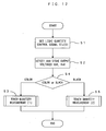
- Fig. 8 is a flow chart showing operations of the toner quantity measuring apparatus which is shown in Fig. 4.
- the control unit 6 outputs the light quantity control signal Slc(0) which corresponds to the turn-off instruction to the irradiation quantity adjusting unit 5 and accordingly turns off the light emitting element 1 (Step S1).
- the dead zone (signal level Slc(0) to Slc(1)) is set up by means of application of the input offset voltage 41, and therefore, the light emitting element 1 is turned off without fail upon application of the light quantity control signal Slc(0).
- An output voltage Vp0 which is indicative of the quantity of the p-polarized light and an output voltage Vs0 which is indicative of the quantity of the s-polarized light in this OFF-state are detected and stored in the memory 62 of the control unit 6 (Step S2).
- a sensor output in the OFF-state, namely, dark output information is detected and stored.
- Step S3 is thereafter executed to derive the quantity of toner adhering on the intermediate transfer belt 141.
- Fig. 9 is a flow chart showing operations of a toner quantity measurement process (1).
- a signal Slc(2) at a signal level beyond the dead zone is set as the light quantity control signal Slc, and the light quantity control signal Slc(2) is supplied to the irradiation quantity adjusting unit 5 to thereby turn on the light element 1 (Step S31).
- the control unit 6 subtracts the dark output voltage Vp0 from the output voltage Vp with respect to the p-polarized light, thereby calculating a light quantity signal SigP2 which represents the quantity of the p-polarized light which corresponds to the toner quantity (Step S33). With respect to the s-polarized light as well, similarly to the p-polarized light, the control unit 6 subtracts the dark output voltage Vs0 from the output voltage Vs to derive a light quantity signal SigS2 which represents the quantity of the s-polarized light which corresponds to the toner quantity (Step S33).
- the dark output voltages Vp0, Vs0 are removed from the measured output voltages Vp, Vs according to this embodiment, it is possible to accurately calculate the light quantities which correspond to the toner quantity. Therefore, even when there is a change in the dark outputs due to an environmental condition, such as an ambient temperature around the apparatus, or a change with time of the components which form the apparatus, it is possible to obtain the outputs which correspond to the toner quantity without an influence of this.
- gains of the respective amplifier circuits 73p, 73s set such that the light quantity signals SigP2, SigS2 as they are when a toner quantity is set to maximum have the same value (SigP2 SigS2), changes in the light quantity signals SigP2, SigS2 in response to the quantity of color toner show as in Fig. 10 and changes in the light quantity signals SigP2, SigS2 in response to the quantity of black toner show as in Fig. 11.
- the dark output voltages Vp0, Vs0 are obtained in advance as dark output information and subtracted, for the purpose of correction, from the output voltages (received light quantity information) Vp, Vs which are detected during measurement of an actual quantity of toner, it is possible to further improve the accuracy of measuring the toner quantity by means of the elimination of an influence of the dark output voltages Vp0, Vs0.
- Vs2/Vp2 an output ratio
- Vs2/Vp2 a correlation between the quantity of the p-polarized light and the quantity of the s-polarized light.
- the control unit 6 not only serves as toner quantity calculating means of the toner quantity measuring apparatus as described above, but adjusts process conditions such as an electrifying bias and a developing bias based on the measurement result (the quantity of adhering toner) if necessary and accordingly controls an image density. This allows to create an image with a stable density.
- toner quantity measuring apparatus according to the first preferred embodiment is incorporated in the image forming apparatus described above, a toner quantity measuring apparatus described below as following preferred embodiments may be incorporated instead
- the toner quantity measurement process (1) is carried out to measure the quantity of toner which adheres to the intermediate transfer belt 141 regardless of a toner color of the toner in the toner quantity measuring apparatus according to the first preferred embodiment above, as Figs. 10 and 11 show, the output voltages change differently with respect to a toner quantity between color toner (Fig. 10) and black toner (Fig. 11).
- a toner quantity measuring apparatus according to a second preferred embodiment, two types of toner quantity measurement processes (1), (2) are prepared in advance and selectively executed in accordance with a toner color of toner adhering on the intermediate transfer belt 141.
- the second preferred embodiment will be described in detail with reference to Figs. 12 and 13.
- Fig. 12 is a flow chart showing operations in the second preferred embodiment of the toner quantity measuring apparatus according to the present invention.
- Steps S1, S2 are executed and a sensor output in the OFF-state, namely, the dark output voltages Vp0, Vs0 are detected and stored.
- Step S4 whether toner adhering to the intermediate transfer belt 141 is color toner or black toner is determined.
- the control unit 6 of an image forming apparatus of this type holds sequence control information which contains an order of forming toner images on the intermediate transfer belt 141 and the sequence control information also contains information regarding a toner color in which an image is being created and information regarding a toner color of a toner image which is positioned in front of the sensor.
- the control unit 6 may execute Step S4 for judgment based on this toner color information.
- Step S4 When it is determined at Step S4 that the toner adhering to the intermediate transfer belt 141 is color toner, the sequence proceeds to Step S3 to carry out the toner quantity measurement process (1). Operations of toner quantity measurement at this stage are exactly the same as those according to the first preferred embodiment, and therefore, will not be described. On the other hand, when it is determined at Step S4 that the toner adhering to the intermediate transfer belt 141 is black toner, the sequence proceeds to Step S5 to carry out the toner quantity measurement process (2).
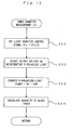
- Fig. 13 is a flow chart showing operations during the toner quantity measurement process (2) shown in Fig. 12.
- the signal Slc(2) which is at a signal level beyond the dead zone is set as the light quantity control signal Slc, and the light quantity control signal Slc(2) is supplied to the irradiation quantity adjusting unit 5 to thereby turn on the light element 1 (Step S51).
- This causes light from the light emitting element 1 to irradiate upon the intermediate transfer belt 141 the reflection quantity detecting unit 7 to detect the quantities of the p-polarized light and the s-polarized light of the light which is reflected by the intermediate transfer belt 141, and the control unit 6 to receive the output voltages Vp, Vs which correspond to the respective light quantities.
- the output voltage Vp regarding the p-polarized light is detected (Step S52).
- the dark output voltage Vp0 is subtracted from the output voltage Vp regarding the p-polarized light and the light quantity signal SigP2 which is indicative of the quantity of the p-polarized light which corresponds to the quantity of black toner is accordingly found (Step S53).
- the dark output voltage Vp0 is removed from the measured output voltage Vp, and hence, it is possible to accurately calculate a light quantity which corresponds to the quantity of the black toner.
- the toner quantity D1 is detected based on the light quantity signal SigP2 which is corrected in the manner above.
- the output voltages representing the p-polarized light and the s-polarized light monotonously decrease in accordance with an increase in black toner quantity as shown in Fig. 11.
- a dynamic range of the p-polarized light is larger than that of the s-polarized light as comparison of the output voltages representing the p-polarized light and the s-polarized light indicates, when measured based on the output voltage representing the p-polarized light whose dynamic range is wider, a toner quantity is more accurately measured.
- the dynamic range of the p-polarized light is larger than that of the s-polarized light because of a characteristic of the beam splitter
- the dynamic range of the s-polarized light can be larger than that of the p-polarized light, in which case it is possible to measure a toner quantity based on an output voltage representing the s-polarized light.
- the second preferred embodiment realizes the following effect in addition to an effect which is similar to that according to the first preferred embodiment. That is, since the two toner quantity measurement processes (1), (2) which are different from each other are prepared in advance and selectively carried out in accordance with a toner color of toner adhering to the intermediate transfer belt 141 according to the second preferred embodiment, it is possible to measure a toner quantity in an optimal measurement flow for each toner color, and therefore, more accurately measure a toner quantity.
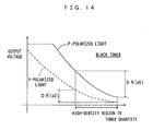
- a reduction rate of an output voltage with respect to a toner quantity is smaller in a high-density region than in a mid- and a low-density regions as indicated at the dotted line in Fig. 14.
- a width of change in output for the high-density region TR is DR(p2).
- the quantity of irradiated light is increased and the output change width in the high-density region is widened to thereby improve a measurement accuracy in the high-density region TR.
- Fig. 15 is a flow chart showing operations in the third preferred embodiment of the toner quantity measuring apparatus according to the present invention.
- the third preferred embodiment requires to execute Steps S1, S2 and detect and store a sensor output in the OFF-state, namely, the dark output voltages Vp0, Vs0.
- Step S4 whether toner adhering to the intermediate transfer belt 141 is color toner or black toner is determined.
- Step S4 determines whether toner adhering to the intermediate transfer belt 141 is color toner or black toner.
- the sequence proceeds to Step S3 to carry out the toner quantity measurement process (1). Operations of toner quantity measurement at this stage are exactly the same as those according to the first preferred embodiment, and therefore, will not be described.
- Step S6 the sequence proceeds to Step S6.
- This type of toner quantity measuring apparatus comprises means which holds image information regarding a toner image which is formed on the intermediate transfer belt 141. Since a general judgment can be made on a toner density of a toner image based on this information, the control unit 6 may make a judgment at Step S6 based on this image information.
- Step S6 When it is determined at Step S6 that the toner density is a middle or low density, the sequence proceeds to Step S5 to carry out the toner quantity measurement process (2). Operations of toner quantity measurement at this stage are exactly the same as those according to the second preferred embodiment, and therefore, will not be described. On the other hand, when it is determined at Step S6 that the toner density is a high density, the sequence proceeds to Step S7 to carry out a toner quantity measurement process (3).
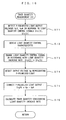
- Fig. 16 is a flow chart of operations during the toner quantity measurement process (3) which is shown in Fig. 15.
- the following is done before a toner image is formed.
- a signal Slc(3) which is at a signal level beyond the dead zone is set as the light quantity control signal Slc, and the light quantity control signal Slc(3) is supplied to the irradiation quantity adjusting unit 5 to thereby turn on the light element 1, and an output voltage Vp3 for the p-polarized light is detected.
- a signal Slc(4) which is at a signal level beyond the light quantity control signal Slc(3) is set as the light quantity control signal Slc, and the light quantity control signal Slc(4) is supplied to the irradiation quantity adjusting unit 5 to thereby turn on the light element 1, and an output voltage Vp4 for the s-polarized light is detected (Step S71).
- a light quantity control characteristic is derived (Step S72). More specifically, as shown in Fig. 17, the light quantity control characteristic is determined based on the output voltage Vp3 in response to the light quantity control signal Slc(3), the output voltage Vp4 in response to the light quantity control signal Slc(4) and the dark output Vp0, and the upper limit value Slc(1) of the dead zone is found. Following this, the signal level of the light quantity control signal is raised from the signal level Slc(2) which is used in the first and the second preferred embodiments to a signal level Slc(5), for the purpose of increasing the quantity of the irradiated light (Step S73). For example, where a light quantity increase rate is to be 3, as shown in Fig.
- changed light quantity control signal Slc(5) is supplied to the irradiation quantity adjusting unit 5 and the light element 1 is consequently turned on. While this causes light from the light emitting element 1 to irradiate upon the intermediate transfer belt 141, the reflection quantity detecting unit 7 to detect the quantities of the p-polarized light and the s-polarized light of the light which is reflected by the intermediate transfer belt 141.
- the control unit 6 receives the output voltages Vp, Vs which correspond to the respective light quantities of the both polarized light. Since the irradiation upon the intermediate transfer belt 141 is greater due to the change made to the light quantity control signal, the output voltage representing the p-polarized light shifts toward the high-voltage side as indicated at the solid line in Fig. 14 and a width of change DR(p5) in output voltage for the high-density region TR widens. In addition, since the value to which the light quantity control signal is set is changed upon deriving of the light quantity control characteristic, it is possible to obtain an output voltage which highly accurately reflects the quantity of toner.
- Step S74 after forming a toner image, the output voltage Vp representing the p-polarized light corresponding to the toner image is detected. Following this, the dark output voltage Vp0 is subtracted from the output voltage Vp, thereby calculating a light quantity signal SigP5 which represents the p-polarized light corresponding to the quantity of black toner in the high-density region (Step S75).
- SigP5 represents the p-polarized light corresponding to the quantity of black toner in the high-density region
- the light quantity signal SigP5 is a value as it is when the irradiation has increased, and hence, at next Step S76, the toner quantity is calculated considering the light quantity increase rate.
- the third preferred embodiment realizes the following effect in addition to an effect which is similar to those according to the first and the second preferred embodiments. That is, according to the third preferred embodiment, when high-density black toner remains adhering on the intermediate transfer belt 141, the quantity of irradiated light is increased and a toner quantity is measured with the width of change in output voltage of the p-polarized light in the high-density region TR widened from DR(p2) to DR(p5). Hence, it is possible to measure the toner quantity with a high accuracy even in the high-density region as well in addition to the mid- and the low-density regions.
- the light quantity increase rate is 3 in the third preferred embodiment above, the light quantity increase rate is not limited to this.
- the quantity of light may be increased at a freely chosen rate.
- the third preferred embodiment above is directed to measurement of black toner on which the quantity of reflected light decreases rapidly, the width of change in output inevitably decreases in the high-density region also for measurement where color toner is used.
- a process similar to that described in relation to "BLACK” may be of course applied to thereby measure the quantity of color toner with an even higher accuracy.
- the gains of the respective amplifier circuits 73p, 73s are set such that the light quantity signals (Vp - Vp0, Vs - Vs0) as they are when a toner quantity is set to maximum have the same value with each other.
- the dynamic range DR(g0) of the output voltage representing the p-polarized light is relatively narrow.
- the gain of the amplifier circuit 73s is increased, as denoted at the solid line in Fig.
- a dynamic range of an output voltage representing the s-polarized light expands into a dynamic range DR(g1), which makes it possible to measure a toner quantity even more accurately.
- a toner quantity measurement process (4) shown in Fig. 19 is executed instead of the toner quantity measurement process (1).
- Fig. 19 is a flow chart showing operations during the toner quantity measurement process (4).
- the signal Slc(2) at a signal level beyond the dead zone is set as the light quantity control signal Slc, and the light quantity control signal Slc(2) is supplied to the irradiation quantity adjusting unit 5 to thereby turn on the light element 1 (Step S81).
- This causes light from the light emitting element 1 to irradiate upon the intermediate transfer belt 141, the reflection quantity detecting unit 7 to detect the quantities of the p-polarized light and the s-polarized light of the light which is reflected by the intermediate transfer belt 141, and the control unit 6 to receive the output voltages Vp, Vs which correspond to the respective light quantities (Step S82).
- the dynamic range of the output voltage representing the s-polarized light is enhanced to the dynamic range DR(g1) from the dynamic range DR(g0).
- Step S83 the light quantity signal SigP2 corresponding to the p-polarized light and light quantity signal SigS2 corresponding to the s-polarized light are calculated from the formulae below:
- SigP ⁇ 2 Vp - Vp ⁇ 0
- SigS ⁇ 2 Vs - Vs ⁇ 0 / M
- the present invention is not limited to the preferred embodiments above but may be modified in a variety of ways other than those described above to the extent not departing from the spirit of the invention.
- the light receiving units 4, 70p, 70s have a structure as that shown in Fig. 5 and the output voltage V0 corresponding to the quantity of received light (the quantity of reflected light) is outputted from the operational amplifier OP of each one of the light receiving units 4, 70p, 70s.
- the variable resistor VR interposed between the output terminal of the operational amplifier OP and the ground potential as shown in Fig. 20 the following effect is obtained. That is, in the light receiving unit shown in Fig.
- variable resistor VR by means of manipulation of the variable resistor VR, it is possible to change a composite resistance R' between this output terminal and the cathode terminal of the light receiving element PS (described as the elements 42, 72p, 72s in the preferred embodiments), and hence, adjust the gain.
- the gain adjustment makes it possible to change the characteristic of the output voltage V0 in response to the quantity of reflected light as shown in Fig. 21.
- a toner quantity is measured more appropriately at an even higher accuracy.
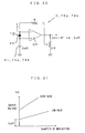
- a solution of this problem may be to insert a variable resistor VR between the non-inversion input terminal and the output terminal of the operational amplifier OP as shown in Fig. 22.
- V ⁇ 0 i ⁇ R ⁇ + Voff the output voltage V0 in response to the quantity of the reflected light changes as shown in Fig. 23.
- the offset voltage where the quantity of the reflected light is zero is always the voltage Voff, which solves the problem described above.
- irradiated light may contain s-polarized light. Even when irradiated light containing p-polarized light and s-polarized light at a ratio of 1 : n (n ⁇ 1) is used, it is possible to measure the quantity of toner in a similar manner to those according to the preferred embodiments above.
- p-polarized light is used as light which is irradiated upon the intermediate transfer belt 141
- irradiated light containing only s-polarized light or containing p-polarized light and s-polarized light at a ratio of m : 1 (m ⁇ 1) may be used instead.
- the present invention is applicable to image forming apparatuses in general comprising a measuring apparatus such as (1) a toner quantity measuring apparatus which receives only one of a plurality of light components, e.g., p-polarized light and measures the quantity of toner based on the quantity of the p-polarized light and (2) a toner quantity measuring apparatus which receives reflected light as it is and measures the quantity of toner based on the quantity of the reflected light.
- a measuring apparatus such as (1) a toner quantity measuring apparatus which receives only one of a plurality of light components, e.g., p-polarized light and measures the quantity of toner based on the quantity of the p-polarized light and (2) a toner quantity measuring apparatus which receives reflected light as it is and measures the quantity of toner based on the quantity of the reflected light.
- the present invention is applicable also to a toner quantity measuring apparatus which measures the quantity of toner adhering on the photosensitive member 121.
- the present invention is applicable to toner quantity measuring apparatuses in general which measure the quantity of toner adhering on an image carrier.
- an image forming apparatus which can mount the toner quantity measuring apparatus according to the present invention is not limited to the apparatus which is shown in Fig. 3.
- the present invention is applicable to image forming apparatuses in general which create a monochrome image or a color image on an image carrier.
Landscapes
- Physics & Mathematics (AREA)
- General Physics & Mathematics (AREA)
- Engineering & Computer Science (AREA)
- Microelectronics & Electronic Packaging (AREA)
- Control Or Security For Electrophotography (AREA)
- Investigating Or Analysing Materials By Optical Means (AREA)
- Dry Development In Electrophotography (AREA)
Applications Claiming Priority (3)
| Application Number | Priority Date | Filing Date | Title |
|---|---|---|---|
| JP2000298905A JP3785914B2 (ja) | 2000-09-29 | 2000-09-29 | 画像形成装置 |
| JP2000306331A JP2002116614A (ja) | 2000-10-05 | 2000-10-05 | 画像形成装置 |
| EP01308336A EP1193566B1 (de) | 2000-09-29 | 2001-09-28 | Vorrichtung zur Messung der Entwicklermenge und damit versehenes Bilderzeugungsgerät |
Related Parent Applications (1)
| Application Number | Title | Priority Date | Filing Date |
|---|---|---|---|
| EP01308336A Division EP1193566B1 (de) | 2000-09-29 | 2001-09-28 | Vorrichtung zur Messung der Entwicklermenge und damit versehenes Bilderzeugungsgerät |
Publications (2)
| Publication Number | Publication Date |
|---|---|
| EP1843217A2 true EP1843217A2 (de) | 2007-10-10 |
| EP1843217A3 EP1843217A3 (de) | 2008-12-03 |
Family
ID=26601122
Family Applications (2)
| Application Number | Title | Priority Date | Filing Date |
|---|---|---|---|
| EP07075571A Withdrawn EP1843217A3 (de) | 2000-09-29 | 2001-09-28 | Tonermengenmessgerät und Bilderzeugungsgerät das Messgerät enthaltend |
| EP01308336A Expired - Lifetime EP1193566B1 (de) | 2000-09-29 | 2001-09-28 | Vorrichtung zur Messung der Entwicklermenge und damit versehenes Bilderzeugungsgerät |
Family Applications After (1)
| Application Number | Title | Priority Date | Filing Date |
|---|---|---|---|
| EP01308336A Expired - Lifetime EP1193566B1 (de) | 2000-09-29 | 2001-09-28 | Vorrichtung zur Messung der Entwicklermenge und damit versehenes Bilderzeugungsgerät |
Country Status (4)
| Country | Link |
|---|---|
| US (1) | US6597878B2 (de) |
| EP (2) | EP1843217A3 (de) |
| AT (1) | ATE389901T1 (de) |
| DE (1) | DE60133249T2 (de) |
Families Citing this family (14)
| Publication number | Priority date | Publication date | Assignee | Title |
|---|---|---|---|---|
| DE60228007D1 (de) * | 2001-01-19 | 2008-09-18 | Seiko Epson Corp | Verfahren und Gerät zur Messung der Tonermenge auf einem bandförmigen Bildträger und Verfahren und Gerät zur Detektierung des Oberflächenzustandes eines bandförmigen Bildträgers |
| CN1237407C (zh) * | 2001-08-31 | 2006-01-18 | 佳能株式会社 | 校正方法和图象形成装置 |
| US6871026B2 (en) * | 2002-08-22 | 2005-03-22 | Seiko Epson Corporation | Apparatus for and method of forming image under controlled image forming condition |
| JP2004078062A (ja) * | 2002-08-22 | 2004-03-11 | Seiko Epson Corp | 画像形成装置および画像形成方法 |
| JP2004109321A (ja) * | 2002-09-17 | 2004-04-08 | Seiko Epson Corp | 画像形成装置および画像形成方法 |
| US7269362B2 (en) * | 2003-05-29 | 2007-09-11 | Seiko Epson Corporation | Image forming apparatus, control method and toner consumption calculating apparatus and method |
| US7680425B2 (en) * | 2003-07-18 | 2010-03-16 | Seiko Epson Corporation | Image forming apparatus and method for controlling tone characteristics based on tone-control patch image |
| JP4594115B2 (ja) * | 2005-01-20 | 2010-12-08 | 京セラミタ株式会社 | 画像形成装置 |
| US7623801B2 (en) * | 2005-03-31 | 2009-11-24 | Seiko Epson Corporation | Image forming apparatus and control method thereof |
| US7929871B2 (en) * | 2008-03-18 | 2011-04-19 | Kabushiki Kaisha Toshiba | Image forming apparatus, image quality management method and image quality management program |
| KR20110039001A (ko) * | 2009-10-09 | 2011-04-15 | 삼성전자주식회사 | 화상형성장치 및 그 장치의 인쇄 품질을 보정하는 방법 |
| JP5885422B2 (ja) * | 2011-08-11 | 2016-03-15 | キヤノン株式会社 | 画像処理装置および画像処理方法 |
| JP5999304B2 (ja) * | 2012-02-17 | 2016-09-28 | 株式会社リコー | 光学センサ及び画像形成装置 |
| JP2017053903A (ja) * | 2015-09-07 | 2017-03-16 | キヤノン株式会社 | 画像形成装置 |
Family Cites Families (20)
| Publication number | Priority date | Publication date | Assignee | Title |
|---|---|---|---|---|
| US4989985A (en) * | 1988-09-19 | 1991-02-05 | Xerox Corporation | Densitometer for measuring specular reflectivity |
| US4950905A (en) * | 1989-02-06 | 1990-08-21 | Xerox Corporation | Colored toner optical developability sensor with improved sensing latitude |
| JP3155555B2 (ja) * | 1991-02-22 | 2001-04-09 | キヤノン株式会社 | カラー画像形成装置 |
| JPH04274734A (ja) * | 1991-03-01 | 1992-09-30 | Ricoh Co Ltd | カラートナー付着状態測定方法及びその装置 |
| JP2729976B2 (ja) * | 1993-02-25 | 1998-03-18 | スタンレー電気株式会社 | 転写形カラープリンタのトナー付着量測定装置 |
| JP3362360B2 (ja) * | 1993-11-05 | 2003-01-07 | オムロン株式会社 | 印刷装置 |
| JP3327659B2 (ja) * | 1993-12-27 | 2002-09-24 | キヤノン株式会社 | 濃度測定装置及び画像形成装置 |
| US5625857A (en) * | 1994-01-18 | 1997-04-29 | Hitachi, Ltd. | Image forming apparatus which measures deposit amounts of toner |
| JP3358099B2 (ja) * | 1994-03-25 | 2002-12-16 | オムロン株式会社 | 光学式センサ装置 |
| US5678132A (en) * | 1994-04-26 | 1997-10-14 | Canon Kabushiki Kaisha | Image density detection adjustment device |
| US5689757A (en) * | 1994-07-18 | 1997-11-18 | Xerox Corporation | Method and apparatus for detecting substrate roughness and controlling print quality |
| JPH08219990A (ja) * | 1995-02-08 | 1996-08-30 | Ricoh Co Ltd | 画像形成装置における反射型光センサ |
| JP3500008B2 (ja) * | 1996-05-28 | 2004-02-23 | 株式会社リコー | 画像形成装置における現像能力検知方法 |
| DE69730920T2 (de) * | 1996-07-26 | 2005-08-25 | Canon K.K. | Bilderzeugungsgerät und dazu montierbare Prozesskassette |
| JPH1063058A (ja) | 1996-08-13 | 1998-03-06 | Konica Corp | 画像形成プロセス制御装置 |
| US5773827A (en) * | 1996-12-16 | 1998-06-30 | Xerox Corporation | Xerographic infrared reflectance densitometer (IRD) sensor |
| JP3218197B2 (ja) | 1996-12-20 | 2001-10-15 | シャープ株式会社 | トナー濃度センサ装置 |
| JP3580068B2 (ja) * | 1997-02-05 | 2004-10-20 | 富士ゼロックス株式会社 | 画像形成装置 |
| JP2000029271A (ja) | 1998-07-10 | 2000-01-28 | Stanley Electric Co Ltd | カラートナー付着量測定装置 |
| JP2000298065A (ja) * | 1999-04-15 | 2000-10-24 | Shinko Denshi Kk | 反射光量検出センサ |
-
2001
- 2001-09-26 US US09/962,154 patent/US6597878B2/en not_active Expired - Fee Related
- 2001-09-28 EP EP07075571A patent/EP1843217A3/de not_active Withdrawn
- 2001-09-28 AT AT01308336T patent/ATE389901T1/de not_active IP Right Cessation
- 2001-09-28 DE DE60133249T patent/DE60133249T2/de not_active Expired - Lifetime
- 2001-09-28 EP EP01308336A patent/EP1193566B1/de not_active Expired - Lifetime
Also Published As
| Publication number | Publication date |
|---|---|
| EP1193566B1 (de) | 2008-03-19 |
| US20020041770A1 (en) | 2002-04-11 |
| US6597878B2 (en) | 2003-07-22 |
| EP1193566A2 (de) | 2002-04-03 |
| EP1843217A3 (de) | 2008-12-03 |
| DE60133249D1 (de) | 2008-04-30 |
| DE60133249T2 (de) | 2009-04-16 |
| EP1193566A3 (de) | 2004-06-16 |
| ATE389901T1 (de) | 2008-04-15 |
Similar Documents
| Publication | Publication Date | Title |
|---|---|---|
| US8797600B2 (en) | Image forming apparatus and gradation correction method with density unevenness detection | |
| EP1843217A2 (de) | Vorrichtung zur Messung einer Tonermenge und Bilderzeugungsvorrichtung mit der Messvorrichtung | |
| US8229307B2 (en) | Image forming apparatus and image forming apparatus control method | |
| CN1323332C (zh) | 图像形成装置及图像形成方法 | |
| US9310742B2 (en) | Image forming apparatus that updates process condition of image formation | |
| US6658221B2 (en) | Method of and apparatus for measuring quantity of toner on belt-shaped image carrier | |
| US20130004188A1 (en) | Image forming apparatus and control method thereof | |
| US8090281B2 (en) | Image forming apparatus and tone correction method | |
| US20060204267A1 (en) | Image forming apparatus | |
| JP2007148080A (ja) | カラー画像形成装置 | |
| US5517283A (en) | Image forming apparatus including improved toner image density detecting arrangement | |
| JP3785914B2 (ja) | 画像形成装置 | |
| US20060291881A1 (en) | Image-forming device | |
| JP2002116614A (ja) | 画像形成装置 | |
| US11630408B2 (en) | Apparatus and method for adjusting output value of optical sensor having light-receiving element that receives regularly-reflected light and diffusely-reflected light | |
| US11507007B2 (en) | Glossiness inspection device, glossiness inspection method, and image forming apparatus | |
| JP3770088B2 (ja) | 画像形成装置 | |
| JP2002169351A (ja) | トナー付着量制御装置、及びトナー付着量制御の方法とこの方法を記録した記録媒体 | |
| JP2007286524A (ja) | 画像形成装置 | |
| JP2002214854A (ja) | 画像形成装置 | |
| KR100601721B1 (ko) | 인쇄장치의 칼라 보정 장치 | |
| JP5994399B2 (ja) | 粉体付着量変換方法及び画像形成装置 | |
| JP2007148259A (ja) | 画像形成装置 | |
| JP2005043917A (ja) | 画像形成装置 | |
| KR100420997B1 (ko) | 인쇄기 및 그 감광매체에 형성된 이미지의 농도측정방법 |
Legal Events
| Date | Code | Title | Description |
|---|---|---|---|
| PUAI | Public reference made under article 153(3) epc to a published international application that has entered the european phase |
Free format text: ORIGINAL CODE: 0009012 |
|
| 17P | Request for examination filed |
Effective date: 20070803 |
|
| AC | Divisional application: reference to earlier application |
Ref document number: 1193566 Country of ref document: EP Kind code of ref document: P |
|
| AK | Designated contracting states |
Kind code of ref document: A2 Designated state(s): AT BE CH CY DE DK ES FI FR GB GR IE IT LI LU MC NL PT SE TR |
|
| AX | Request for extension of the european patent |
Extension state: AL LT LV MK RO SI |
|
| PUAL | Search report despatched |
Free format text: ORIGINAL CODE: 0009013 |
|
| AK | Designated contracting states |
Kind code of ref document: A3 Designated state(s): AT BE CH CY DE DK ES FI FR GB GR IE IT LI LU MC NL PT SE TR |
|
| AX | Request for extension of the european patent |
Extension state: AL LT LV MK RO SI |
|
| AKX | Designation fees paid |
Designated state(s): DE FR GB |
|
| 17Q | First examination report despatched |
Effective date: 20100827 |
|
| STAA | Information on the status of an ep patent application or granted ep patent |
Free format text: STATUS: THE APPLICATION HAS BEEN WITHDRAWN |
|
| 18W | Application withdrawn |
Effective date: 20101015 |