EP1843225A1 - Mechanischer Wechsler zum Drehantreiben eines Rades aus einer einzelnen Richtung - Google Patents
Mechanischer Wechsler zum Drehantreiben eines Rades aus einer einzelnen Richtung Download PDFInfo
- Publication number
- EP1843225A1 EP1843225A1 EP06007364A EP06007364A EP1843225A1 EP 1843225 A1 EP1843225 A1 EP 1843225A1 EP 06007364 A EP06007364 A EP 06007364A EP 06007364 A EP06007364 A EP 06007364A EP 1843225 A1 EP1843225 A1 EP 1843225A1
- Authority
- EP
- European Patent Office
- Prior art keywords
- wheel
- mechanism according
- driving
- axis
- driving wheel
- Prior art date
- Legal status (The legal status is an assumption and is not a legal conclusion. Google has not performed a legal analysis and makes no representation as to the accuracy of the status listed.)
- Granted
Links
Images


Classifications
-
- G—PHYSICS
- G04—HOROLOGY
- G04B—MECHANICALLY-DRIVEN CLOCKS OR WATCHES; MECHANICAL PARTS OF CLOCKS OR WATCHES IN GENERAL; TIME PIECES USING THE POSITION OF THE SUN, MOON OR STARS
- G04B13/00—Gearwork
- G04B13/005—Gearwork where a revolution in both directions is changed into a revolution in one direction
-
- F—MECHANICAL ENGINEERING; LIGHTING; HEATING; WEAPONS; BLASTING
- F16—ENGINEERING ELEMENTS AND UNITS; GENERAL MEASURES FOR PRODUCING AND MAINTAINING EFFECTIVE FUNCTIONING OF MACHINES OR INSTALLATIONS; THERMAL INSULATION IN GENERAL
- F16D—COUPLINGS FOR TRANSMITTING ROTATION; CLUTCHES; BRAKES
- F16D41/00—Freewheels or freewheel clutches
- F16D41/06—Freewheels or freewheel clutches with intermediate wedging coupling members between an inner and an outer surface
- F16D41/069—Freewheels or freewheel clutches with intermediate wedging coupling members between an inner and an outer surface the intermediate members wedging by pivoting or rocking, e.g. sprags
-
- F—MECHANICAL ENGINEERING; LIGHTING; HEATING; WEAPONS; BLASTING
- F16—ENGINEERING ELEMENTS AND UNITS; GENERAL MEASURES FOR PRODUCING AND MAINTAINING EFFECTIVE FUNCTIONING OF MACHINES OR INSTALLATIONS; THERMAL INSULATION IN GENERAL
- F16D—COUPLINGS FOR TRANSMITTING ROTATION; CLUTCHES; BRAKES
- F16D41/00—Freewheels or freewheel clutches
- F16D41/06—Freewheels or freewheel clutches with intermediate wedging coupling members between an inner and an outer surface
- F16D41/069—Freewheels or freewheel clutches with intermediate wedging coupling members between an inner and an outer surface the intermediate members wedging by pivoting or rocking, e.g. sprags
- F16D41/07—Freewheels or freewheel clutches with intermediate wedging coupling members between an inner and an outer surface the intermediate members wedging by pivoting or rocking, e.g. sprags between two cylindrical surfaces
- F16D41/076—Freewheels or freewheel clutches with intermediate wedging coupling members between an inner and an outer surface the intermediate members wedging by pivoting or rocking, e.g. sprags between two cylindrical surfaces the wedging coupling members being non-releasably joined to form a single annular piece, e.g. either the members being integral projections from the piece, or the piece being an elastic ring cast round the radial centres of the members
-
- G—PHYSICS
- G04—HOROLOGY
- G04B—MECHANICALLY-DRIVEN CLOCKS OR WATCHES; MECHANICAL PARTS OF CLOCKS OR WATCHES IN GENERAL; TIME PIECES USING THE POSITION OF THE SUN, MOON OR STARS
- G04B13/00—Gearwork
- G04B13/02—Wheels; Pinions; Spindles; Pivots
-
- G—PHYSICS
- G04—HOROLOGY
- G04B—MECHANICALLY-DRIVEN CLOCKS OR WATCHES; MECHANICAL PARTS OF CLOCKS OR WATCHES IN GENERAL; TIME PIECES USING THE POSITION OF THE SUN, MOON OR STARS
- G04B5/00—Automatic winding up
- G04B5/02—Automatic winding up by self-winding caused by the movement of the watch
Definitions
- the present invention relates to an inverter mechanism that allows to drive the first mobile of a kinematic chain in one direction, regardless of the direction of rotation of the drive pinion.
- Such inverter devices are used in particular for the automatic winding of the mainspring of a mechanical watch, or to drive the generator of any small portable electronic device, the drive gear being generally set in motion by an oscillating mass.
- the present invention therefore aims to overcome the drawbacks of the aforementioned prior art by providing an inverter mechanism comprising a smaller number of parts to be assembled and can therefore be produced at lower cost, while having greater or equal performance than the devices of the prior art.
- the reversing mechanism interposed between the first wheel of a kinematic chain to be driven in one direction and the reciprocating motor pinion, comprises a driving wheel engaged with said motor pinion mounted on an axis of rotation at above a driven wheel mounted on the same axis and engaged, directly or indirectly with the first wheel of the driveline.
- the driven wheel comprises a bowl open towards the driving wheel to house a clutch device, made of a resilient material, for coupling / uncoupling the two wheels depending on the direction of rotation of the motor pinion.
- the clutch device is characterized in that it comprises at least one arm of recurve lock, one end of which has a point of pivoting on the drive wheel and the other end of which has a fulcrum against the inner wall of the bowl of the wheel driven under the action of a spring coming from material with said arms.
- the pivoting of the arm takes place around a fixed axis integral with the driving wheel, and according to a second embodiment, which will be explained in more detail later, the pivot point can move along a cam integral with the driving wheel.
- the operation can be further improved by providing at the level of the locking arm a guide extension providing a third positioning point of said locking arm, an extension of balancing to reduce or even eliminate the unbalance, and / or a safety device limiting the stroke of the pivot point along the cam in case of too violent deflections.
- the inverter mechanism briefly described above is called “one way” because it is only motor for a single alternation of the drive sprocket. It is possible, however, to have a "two-way” reversing device by coupling two "one-way” reversing mechanisms with inverted clutch devices. In a preferred embodiment, the two reversing mechanisms are superimposed and the two driven wheels form a single piece.
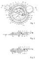
- FIGS. 1 and 2 a first embodiment of an inverter mechanism according to the invention, which will be illustrated by way of example by an automatic winding mechanism of a watch, is described below.
- mechanical by an oscillating mass whose motor pinion 3 acts in one direction to drive the first mobile 1 of a reduction kinematic chain (not shown) whose last mobile is in engagement with the barrel ratchet.
- the driving gear 3 of the oscillating weight meshes with a first driving gear 5 mounted idly on an axis of rotation 6 pivoted between a plate and a bridge (not shown), or between any other frame for positioning the parts of a mechanism watchmaker to each other.
- a second driven wheel 7 is positioned below the driving wheel 5 while being also mounted idle on the axis of rotation 6. It also has a toothing engaged with the first mobile 1 of the drive train.
- the driven wheel 7 comprises a bowl 11 whose opening is oriented towards the driving wheel 5.
- This bowl 11 is intended to house a clutch device 10 whose Embodiment is described below.
- the clutch device 10 basically comprises two parts, which can be made in one piece, or constitute two separate parts.
- the first part is constituted by a locking arm 12 which, in this embodiment, is curved, one end 14, designated “foot”, has a pivot point 14a in the drive wheel 5, for example around an axis 24 driven into said wheel.
- the other end 16 of the arm 12, designated “head”, provides a fulcrum 16a against the inner wall 2 of the bowl 11.
- This support is provided by a spring 20 connecting the head 16 and an attachment point 22 in the drive wheel 5.
- This spring 20 has been shown with a shape of circular arc between its two junction points, but it is obvious that it could have a completely different outline depending on the construction requirements, without departing from the scope of the present invention.
- the angle formed by the axis 6 with the pivot point 14a and the fulcrum 16a is an obtuse angle, slightly less than 180 °, making the arm allows the free rotation of the driving wheel 5 in one direction, without driving the driven wheel 7, and instead drives the driven wheel 7 when the driving wheel 5 rotates in the other direction, as will be described in more detail in reference to the second embodiment.
- the sectional representation of FIG. 3 concerns a variant of the first embodiment concerning the location of the power take-offs on the driving wheel 5 and on the driven wheel 7.
- the essential thing is that the driving wheel 5 and the driven wheel 7 are free to rotate relative to each other when the clutch mechanism 10 does not intervene.
- the driven wheel 7 no longer has toothing but is driven on an additional pinion 8, itself secured to the axis 6, while the driving wheel 5 remains mounted mad on said axis 6.
- the first mobile 1 of the kinematic chain then meshes with the additional pinion 8.
- the additional pinion 8 could be made integral with the driving wheel 5, being or not driven on the axis 6, the driven wheel 7 while being mounted mad on said axis 6.
- FIGS. 4 and 5 a second embodiment which differs from that previously described by the arrangement of the clutch device 10 is described below.
- the joint construction details will therefore not be further described and will the same references.
- the foot 14 of the locking arm 12 is no longer pivoted in the drive wheel 5, but its pivot point 14b can move on the edge of a guide cam 21, constituted by a plate secured to the driving wheel 5, for example by means of two pins 23.
- the spring 20 connects the head 16 and the cam 21 to maintain the fulcrum 16a in contact with the wall 2 of the bowl 11.
- the contour of the cam 21 is designed to minimize the "dead angle", ie the angle that the driving wheel 5 must travel before driving the driven wheel 7. With the clutch device according to the invention, this blind spot is reduced to a value less than 2 ° whereas it is of the order of 26 ° in the reversing mechanisms of the prior art.
- the curvature of the cam is for example of the exponential type, but other choices within the reach of the skilled person are possible.
- the operation of this clutch mechanism is explained later after the description of a first variant of this second mode.
- Figure 6 is a simplified representation of a first variant of the second embodiment.
- the head 16 of the locking arm 12 is extended, opposite the junction with the spring 20, by a guide extension 13 forming a third bearing point 13a on the wall 2 of the bowl 11 to better control the positioning of the locking fulcrum 16a.
- This variant will be taken up later to better understand the operation of the inverter mechanism according to the invention.
- FIG. 7 is a simplified representation of a second variant which differs from the preceding variant in that the guide extension 13 is no longer guided by the wall 2 of the bowl 11 but by a guide plate 26 situated in the cup 11, below the drive wheel 5 and secured thereto for example by means of pins 28.
- FIG 8 is a simplified representation of a third variant which can also integrate one or the other of the two previous variants.
- a safety device is provided to prevent the pivot point 14b from coming out of the cam 21 in the event of strong deflections of the driving wheel 5.
- This safety device consists, in the example represented, in a spout 15 , formed from the foot 14 of the locking arm 12, which cooperates with a recess 25 formed in an extension of the plate forming the cam 21.
- the skilled person can obviously design another arrangement of this safety device, without leaving of the scope of the present invention.
- Figure 9 is a simplified representation of a fourth variant which can also integrate the previous variants.
- the center of gravity of a moving part it is desirable for the center of gravity of a moving part to coincide with its axis of rotation in order to avoid an unbalance that is unfavorable to the efficiency of the device.
- the center of gravity of the assembly forming the clutch device 10 can not coincide with the axis of rotation 6.
- This fourth variant makes it possible to remedy this disadvantage by providing at least one balancing extension 17 whose geometry is calculated to bring into coincidence the center of gravity of the clutch device 10 and the center of the axis of rotation 6.
- the clutch device that has just been described, according to one or other of the embodiments, is a one-piece device made of a material that must have a certain elasticity because of the spring 20. It can be made of metal or alloy by known methods of micromachining, such as laser cutting, wire EDM, or by methods used for the manufacture of MEMs, such as the LIGA technique.
- the material used may also be non-metallic such as silicon, silicon dioxide, glass, or other silicon compounds, quartz or diamond using, for example, masking and etching methods to obtain the desired contour. These methods of manufacture are well known to those skilled in the art and therefore will not be described further.
- FIG. 10 corresponds to the clutch device 10, after fixing of the guide cam 21 in the driving wheel 5 by means of the pegs 23, but before final positioning in the bowl 11 of the driven wheel 7.
- the foot 14 of the arm 12 is not in contact with the cam 21, and the head 16 and the end of the guide extension 13 extend beyond the inner wall 2 of the bowl 11.
- the spring 20 will force the head 16 and the guide extension 13 to bear against the inner wall 11a of the bowl 11.
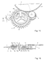
- FIGS. 13 to 16 a third and fourth embodiment is described below relating to a "two-way" reversing mechanism which basically consists in coupling a first single-direction reversing mechanism, whose references will be followed by the letter "a” and a second simple meaning mechanism whose references will be followed by the letter "b".
- the two reversing mechanisms are located in the same plane, the driving wheels 5a, 5b both meshing with the driving pinion 3, the driven wheels 7a, 7b meshing with each other.
- the clutch devices 10a, 10b are arranged in their respective cups 11a, 11b to have opposite actions.
- the clutch devices 10a, 10b are mirror images of each other. It is quite obvious, without departing from the scope of the invention, that other arrangements are possible, for example by using a deflection wheel which would make it possible to dispose them again either in a planar manner or superimposed way, the devices of clutch 10a, 10b then having the same orientation.
- FIG. 13 is represented by a solid line arrow in the direction of rotation of the mobiles when the alternation of the motor pinion 3 is effected in the clockwise direction, and by a double-pointed arrow when the alternation is effected. in the opposite direction.
- the pinion 3 drives the driving wheel 5b, which in turn causes the driven wheel 7b to lock, which itself drives the first pinion 1 of the drive train in a clockwise direction.
- the driven wheel 7b also meshes with the driven wheel 7b and is indeed not impeded in rotation by the driving wheel 5a, which is also rotated by the driving pinion 3, but which rotates in the opposite direction to the driving wheel 5a. by being free in rotation.
- FIGS 15 and 16 describe a fourth embodiment, which may also be understood as an alternative of the previous embodiment when the two clutch mechanisms are superimposed.
- the motor pinion 3 meshes with the driving wheel 5a of the first clutch mechanism and, via a return 4, with the driving wheel 5b of the second clutch mechanism.
- This fourth embodiment is characterized in that the driven wheels 7a and 7b form a junction plate 9 in which are formed on both sides the cups 11a, 11b intended to receive the mechanisms 10a, 10b, which in this case have the same orientation, but allow to have actions reversed because of the referral 4. The operation will not be explained because it follows naturally from what has been said for the third embodiment.
- Such an inverter mechanism can be used in a very small portable device to supply its source of mechanical or electrical energy, such as a wristwatch, when the drive pinion is driven by an oscillating mass. It can also find other applications, for example for the winding stem by providing a gear bevel gear.
- the invention is not limited to the embodiments that have just been described, since the person skilled in the art can adapt them as needed, for example for a particular watch gauge, or for a non-watchmaking application.
Landscapes
- Engineering & Computer Science (AREA)
- General Engineering & Computer Science (AREA)
- Physics & Mathematics (AREA)
- General Physics & Mathematics (AREA)
- Mechanical Engineering (AREA)
- Transmission Devices (AREA)
- Gears, Cams (AREA)
- Gear Transmission (AREA)
Priority Applications (7)
| Application Number | Priority Date | Filing Date | Title |
|---|---|---|---|
| ES06007364T ES2327350T3 (es) | 2006-04-07 | 2006-04-07 | Mecanismo inversor para accionamiento rotativo unidireccional de un movil. |
| DE602006007807T DE602006007807D1 (de) | 2006-04-07 | 2006-04-07 | Mechanischer Wechsler zum Drehantreiben eines Rades aus einer einzelnen Richtung |
| EP06007364A EP1843225B1 (de) | 2006-04-07 | 2006-04-07 | Mechanischer Wechsler zum Drehantreiben eines Rades aus einer einzelnen Richtung |
| US11/695,701 US7287901B1 (en) | 2006-04-07 | 2007-04-03 | Reverser mechanism for uni-directional rotational driving of a wheel set |
| JP2007100392A JP5064084B2 (ja) | 2006-04-07 | 2007-04-06 | フォイール・セットの単方向回転駆動のためのリバーサ機構 |
| CN200710091100XA CN101051213B (zh) | 2006-04-07 | 2007-04-09 | 用于轮副的单向旋转驱动的换向机构 |
| HK07113755.1A HK1108495B (en) | 2006-04-07 | 2007-12-18 | Reverser mechanism for uni-directional rotational driving of a wheel set |
Applications Claiming Priority (1)
| Application Number | Priority Date | Filing Date | Title |
|---|---|---|---|
| EP06007364A EP1843225B1 (de) | 2006-04-07 | 2006-04-07 | Mechanischer Wechsler zum Drehantreiben eines Rades aus einer einzelnen Richtung |
Publications (2)
| Publication Number | Publication Date |
|---|---|
| EP1843225A1 true EP1843225A1 (de) | 2007-10-10 |
| EP1843225B1 EP1843225B1 (de) | 2009-07-15 |
Family
ID=37667079
Family Applications (1)
| Application Number | Title | Priority Date | Filing Date |
|---|---|---|---|
| EP06007364A Expired - Lifetime EP1843225B1 (de) | 2006-04-07 | 2006-04-07 | Mechanischer Wechsler zum Drehantreiben eines Rades aus einer einzelnen Richtung |
Country Status (6)
| Country | Link |
|---|---|
| US (1) | US7287901B1 (de) |
| EP (1) | EP1843225B1 (de) |
| JP (1) | JP5064084B2 (de) |
| CN (1) | CN101051213B (de) |
| DE (1) | DE602006007807D1 (de) |
| ES (1) | ES2327350T3 (de) |
Cited By (6)
| Publication number | Priority date | Publication date | Assignee | Title |
|---|---|---|---|---|
| EP2263825A1 (de) * | 2009-06-16 | 2010-12-22 | Blösch Ressourcen AG | Verfahren zur Herstellung von Werkstücken aus einer Materialplatte |
| WO2014180459A1 (de) * | 2013-05-06 | 2014-11-13 | Kiekert Aktiengesellschaft | Kleinstantrieb für automobilschlösser mit laufrichtungssperre |
| US9298163B2 (en) | 2013-11-06 | 2016-03-29 | Eta Sa Manufacture Horlogere Suisse | Timepiece wheel set with a unidirectional wheel |
| CN110219951A (zh) * | 2019-05-14 | 2019-09-10 | 梅苏鸿 | 换向机构 |
| EP3705949A1 (de) * | 2019-03-05 | 2020-09-09 | ETA SA Manufacture Horlogère Suisse | Drehmomentbegrenzungsmechanismus eines uhrwerks |
| EP4198640A1 (de) | 2021-12-15 | 2023-06-21 | Richemont International S.A. | Planetengetriebegleichrichter und automatikaufzug für uhren |
Families Citing this family (25)
| Publication number | Priority date | Publication date | Assignee | Title |
|---|---|---|---|---|
| DE102007046689B4 (de) * | 2007-06-01 | 2009-09-17 | Konrad Damasko | Mechanischer Aufzug für Armbanduhren sowie Armbanduhr mit einem solchen Aufzug |
| EP2060534A1 (de) * | 2007-11-16 | 2009-05-20 | Nivarox-FAR S.A. | Mikromechanisches Bauteil aus Silizium-Metall-Verbundmaterial und Verfahren zu dessen Herstellung |
| EP2154582A1 (de) * | 2008-08-15 | 2010-02-17 | Nivarox-FAR S.A. | Verzahnungverfahren für Uhrwerk |
| EP2175329B1 (de) * | 2008-12-01 | 2011-02-16 | The Swatch Group Research and Development Ltd. | Uhrwerk, das mit einem Vibrationswecker ausgestattet ist |
| ES2423285T3 (es) * | 2009-03-03 | 2013-09-19 | Montres Jaquet Droz Sa | Dispositivo de desembrague para mecanismo de relojería, y movimiento de reloj comprendiendo este dispositivo |
| EP2264550A1 (de) * | 2009-06-16 | 2010-12-22 | Samep S.A. - Montres Emile Pequignet | Rad für Wechselrichter, Herstellungsverfahren eines solchen Rads und Wechselrichtern für mit einem solchen Rad ausgestattetes Uhrwerk |
| CH702924B1 (fr) * | 2010-06-03 | 2011-10-14 | Patek Philippe Sa Geneve | Mobile à embrayage unidirectionnel, mécanisme de remontage et pièce d'horlogerie comportant ledit mobile. |
| EP2397921B1 (de) * | 2010-06-17 | 2017-08-30 | Blancpain S.A. | Mechanismus für springendes Karussell-Gestell |
| US9599965B2 (en) * | 2010-06-22 | 2017-03-21 | The Swatch Group Research And Development Ltd | Process for adjusting the relative position of a first and a second piece of a mechanical assembly |
| EP2596406B1 (de) * | 2010-07-19 | 2019-03-27 | Nivarox-FAR S.A. | Oszillationsmechanismus mit elastischem und mobilem drehzapfen zur energieübertragung |
| EP2586879A1 (de) * | 2011-10-27 | 2013-05-01 | Nivarox-FAR S.A. | Verfahren zur thermischen Behandlung von mikromechanischen Bauteilen von Uhren |
| EP2897000B1 (de) * | 2014-01-15 | 2017-02-01 | Audemars Piguet (Renaud et Papi) SA | Wendegetriebe für Uhr |
| CH710188A2 (fr) * | 2014-09-26 | 2016-03-31 | Eta Sa Manufacture Horlogère Suisse | Résonateur d'horlogerie paraxial et isochrone. |
| EP3009896B1 (de) * | 2014-10-17 | 2020-03-11 | Nivarox-FAR S.A. | Elektrogeformtes monoblock-metallteil |
| EP3018535B1 (de) * | 2014-11-07 | 2018-09-05 | Montres Breguet SA | Aufziehvorrichtung mit unidirektionaler Antriebsanordnung |
| EP3021173B1 (de) * | 2014-11-14 | 2017-05-24 | Blancpain S.A. | Ringförmige Schwungmasse und Uhr, die eine solche Schwungmasse umfasst |
| EP3021174A1 (de) * | 2014-11-17 | 2016-05-18 | LVMH Swiss Manufactures SA | Monolithischer Uhrregler, Uhrwerk und Uhr mit einem solchem Uhrregler |
| ES2657167T3 (es) * | 2015-06-11 | 2018-03-01 | Société Anonyme de la Manufacture d'Horlogerie Audemars Piguet & Cie | Inversor de relojería y reloj con remontaje automático que comprende su aplicación |
| EP3163381B1 (de) * | 2015-10-26 | 2019-06-26 | The Swatch Group Research and Development Ltd. | Automatisches aufziehen einer armbanduhr |
| US10317842B2 (en) * | 2016-04-25 | 2019-06-11 | Seiko Epson Corporation | Timepiece mainspring, timepiece drive device, timepiece movement, timepiece, and manufacturing method of timepiece mainspring |
| CN106406066B (zh) * | 2016-06-29 | 2018-07-20 | 辽宁孔雀表业有限公司 | 一种自动手表的外齿行星轮式换向机构 |
| CN106286636B (zh) * | 2016-11-08 | 2018-08-07 | 天津铁路信号有限责任公司 | 一种电动转辙机用滚柱式双向逆止器 |
| JP7023124B2 (ja) * | 2018-01-26 | 2022-02-21 | セイコーインスツル株式会社 | ムーブメントおよび時計 |
| CN111449817B (zh) * | 2020-04-21 | 2022-02-22 | 合肥瑞欣康复用品用具有限责任公司 | 一种矫形器的生产工艺及其流水线 |
| CH718176A1 (fr) * | 2020-12-16 | 2022-06-30 | Mft Dhorlogerie Audemars Piguet Sa | Mécanisme de transmission pour mouvement horloger et mécanisme de remontage automatique le comportant. |
Citations (7)
| Publication number | Priority date | Publication date | Assignee | Title |
|---|---|---|---|---|
| US2645319A (en) * | 1950-05-03 | 1953-07-14 | Robin Leo | Free wheel mechanism |
| CH305463A (fr) | 1952-03-12 | 1955-02-28 | Chs Tissot & Fils S A | Montre à remontage automatique par les mouvements dans les deux sens de rotation d'une masse mobile. |
| GB814535A (en) * | 1955-10-11 | 1959-06-10 | Otto Epple | Automatic winding device for watches, preferably for wrist-watches |
| CH400017A (de) * | 1963-12-24 | 1966-04-15 | Ebauches Sa | Uhr mit Schwungmassen-Selbstaufzug |
| CH412721A (fr) * | 1961-07-06 | 1966-11-30 | Fontainemelon Horlogerie | Remontoir pour pièce d'horlogerie |
| JPS4718706U (de) | 1971-04-01 | 1972-11-01 | ||
| DE2851735A1 (de) * | 1978-11-30 | 1980-06-04 | Durowe Gmbh | Waelzkoerperrichtgesperr |
Family Cites Families (10)
| Publication number | Priority date | Publication date | Assignee | Title |
|---|---|---|---|---|
| JPS5741751Y2 (de) * | 1977-10-15 | 1982-09-13 | ||
| JPS6138585U (ja) * | 1984-08-10 | 1986-03-11 | 中川電化産業株式会社 | ラチエツト機構 |
| JPS61141822U (de) * | 1985-02-25 | 1986-09-02 | ||
| JPS62183853A (ja) | 1986-02-07 | 1987-08-12 | Toyo C C I Kk | 一酸化炭素転化触媒 |
| US4809250A (en) * | 1988-01-29 | 1989-02-28 | Fabrique Ebel, Societe Anonyme | Reverser mechanism for an automatic winding arrangement |
| CN2121039U (zh) * | 1992-04-29 | 1992-11-04 | 广州明珠表业有限公司 | 自动手表的换向机构 |
| EP1046965B1 (de) * | 1999-04-23 | 2004-08-18 | Rolex Sa | Uhrwerk mit Schwungmassen-Selbstaufzug |
| EP1152303B1 (de) * | 2000-05-05 | 2006-07-19 | Rolex Sa | Uhr mit Aufzugsmechanismus und mit Korrekturmechanismus für mindestens zwei anzeigende Organe |
| CN1374570A (zh) * | 2001-10-10 | 2002-10-16 | 刘越雄 | 自动手表双杆互锁式换向机构及其互锁换向方法 |
| JP2004170270A (ja) * | 2002-11-20 | 2004-06-17 | Seiko Instruments Inc | 規正装置を備えた自動巻時計 |
-
2006
- 2006-04-07 EP EP06007364A patent/EP1843225B1/de not_active Expired - Lifetime
- 2006-04-07 DE DE602006007807T patent/DE602006007807D1/de not_active Expired - Lifetime
- 2006-04-07 ES ES06007364T patent/ES2327350T3/es not_active Expired - Lifetime
-
2007
- 2007-04-03 US US11/695,701 patent/US7287901B1/en active Active
- 2007-04-06 JP JP2007100392A patent/JP5064084B2/ja active Active
- 2007-04-09 CN CN200710091100XA patent/CN101051213B/zh active Active
Patent Citations (7)
| Publication number | Priority date | Publication date | Assignee | Title |
|---|---|---|---|---|
| US2645319A (en) * | 1950-05-03 | 1953-07-14 | Robin Leo | Free wheel mechanism |
| CH305463A (fr) | 1952-03-12 | 1955-02-28 | Chs Tissot & Fils S A | Montre à remontage automatique par les mouvements dans les deux sens de rotation d'une masse mobile. |
| GB814535A (en) * | 1955-10-11 | 1959-06-10 | Otto Epple | Automatic winding device for watches, preferably for wrist-watches |
| CH412721A (fr) * | 1961-07-06 | 1966-11-30 | Fontainemelon Horlogerie | Remontoir pour pièce d'horlogerie |
| CH400017A (de) * | 1963-12-24 | 1966-04-15 | Ebauches Sa | Uhr mit Schwungmassen-Selbstaufzug |
| JPS4718706U (de) | 1971-04-01 | 1972-11-01 | ||
| DE2851735A1 (de) * | 1978-11-30 | 1980-06-04 | Durowe Gmbh | Waelzkoerperrichtgesperr |
Cited By (9)
| Publication number | Priority date | Publication date | Assignee | Title |
|---|---|---|---|---|
| EP2263825A1 (de) * | 2009-06-16 | 2010-12-22 | Blösch Ressourcen AG | Verfahren zur Herstellung von Werkstücken aus einer Materialplatte |
| EP2263824A1 (de) * | 2009-06-16 | 2010-12-22 | BCI Blösch Corporation Inc. | Verfahren zur Herstellung von Werkstüchen aus einer Materialplatte |
| WO2014180459A1 (de) * | 2013-05-06 | 2014-11-13 | Kiekert Aktiengesellschaft | Kleinstantrieb für automobilschlösser mit laufrichtungssperre |
| US10400859B2 (en) | 2013-05-06 | 2019-09-03 | Kiekert Aktiengesellschaft | Miniature drive for automobile locks with running direction lock |
| US9298163B2 (en) | 2013-11-06 | 2016-03-29 | Eta Sa Manufacture Horlogere Suisse | Timepiece wheel set with a unidirectional wheel |
| EP3705949A1 (de) * | 2019-03-05 | 2020-09-09 | ETA SA Manufacture Horlogère Suisse | Drehmomentbegrenzungsmechanismus eines uhrwerks |
| US11768464B2 (en) | 2019-03-05 | 2023-09-26 | Eta Sa Manufacture Horlogere Suisse | Horological torque limiting mechanism |
| CN110219951A (zh) * | 2019-05-14 | 2019-09-10 | 梅苏鸿 | 换向机构 |
| EP4198640A1 (de) | 2021-12-15 | 2023-06-21 | Richemont International S.A. | Planetengetriebegleichrichter und automatikaufzug für uhren |
Also Published As
| Publication number | Publication date |
|---|---|
| CN101051213B (zh) | 2010-04-14 |
| DE602006007807D1 (de) | 2009-08-27 |
| JP5064084B2 (ja) | 2012-10-31 |
| CN101051213A (zh) | 2007-10-10 |
| EP1843225B1 (de) | 2009-07-15 |
| ES2327350T3 (es) | 2009-10-28 |
| JP2007279045A (ja) | 2007-10-25 |
| US20070237035A1 (en) | 2007-10-11 |
| US7287901B1 (en) | 2007-10-30 |
| HK1108495A1 (zh) | 2008-05-09 |
Similar Documents
| Publication | Publication Date | Title |
|---|---|---|
| EP1843225B1 (de) | Mechanischer Wechsler zum Drehantreiben eines Rades aus einer einzelnen Richtung | |
| EP1918789B1 (de) | Schwingmasse zum Wiederaufladen der Energiequelle eines tragbaren Instruments | |
| EP2397920A1 (de) | Mechanismus für springendes Tourbillon-Gestell oder Karussell-Gestell | |
| EP2376986B1 (de) | Uhrwerk mit automatischer aufzugvorrichtung und bewegungshemmung | |
| WO2017102916A1 (fr) | Mécanisme de réglage d'une vitesse moyenne dans un mouvement d'horlogerie et mouvement d'horlogerie | |
| EP3040783B1 (de) | Untereinheit für einen mechanismus zur einstellung der geschwindigkeit in einem uhrwerk, und ein solcher mechanismus | |
| EP2690507A1 (de) | Spiralfeder einer Uhr | |
| EP3382468B1 (de) | Uhrwerk mit verlängerung der gangreserve | |
| EP3889689B1 (de) | Antriebsorgan für uhr | |
| EP3557334A1 (de) | Uhrhemmungsmechanismus mit ruheanker, und uhr, die mit einem solchen hemmungsmechanismus ausgestattet ist | |
| EP1615085A1 (de) | Korrekturmechanismus von einem Teller einer Regulierungsvorrichtung für ein Uhruh-Spiralfeder | |
| EP3021173A1 (de) | Ringförmige Schwungmasse und Uhr, die eine solche Schwungmasse umfasst | |
| EP3599514B1 (de) | Hemmungsmechanismus mit bistabilen und monostabilen federn | |
| EP2054780A2 (de) | Steuereinrichtung für eine uhr | |
| EP3203326B1 (de) | Konvertierungsmechanismus für einer rotationsbewegung in jeder drehrichtung in einer bewegung mit einer einzelen bewegung richtung. | |
| CH715052A2 (fr) | Mécanisme à couple constant, mouvement de pièce d'horlogerie, et pièce d'horlogerie. | |
| EP3376308B1 (de) | Aufziehmechanismus einer uhr | |
| CH713407A2 (fr) | Système de remontage pour pièce d'horlogerie. | |
| WO2019092664A1 (fr) | Organe moteur d'horlogerie. | |
| EP2053474B1 (de) | Chronographenuhr | |
| EP3786727A1 (de) | Animationsmechanismus eines objekts für schmuck- oder juwelierartikel | |
| EP3779606A1 (de) | Armbanduhr mit automatischem aufzug | |
| EP3783444B1 (de) | Uhrwerkmechanismus, der eine blockiervorrichtung umfasst | |
| EP3969964B1 (de) | Uhrwerk einer armbanduhr mit automatischem aufzug | |
| EP4432018A1 (de) | Uhrwerk, das einen automatischen aufzugsmechanismus umfasst |
Legal Events
| Date | Code | Title | Description |
|---|---|---|---|
| PUAI | Public reference made under article 153(3) epc to a published international application that has entered the european phase |
Free format text: ORIGINAL CODE: 0009012 |
|
| AK | Designated contracting states |
Kind code of ref document: A1 Designated state(s): AT BE BG CH CY CZ DE DK EE ES FI FR GB GR HU IE IS IT LI LT LU LV MC NL PL PT RO SE SI SK TR |
|
| AX | Request for extension of the european patent |
Extension state: AL BA HR MK YU |
|
| 17P | Request for examination filed |
Effective date: 20080410 |
|
| AKX | Designation fees paid |
Designated state(s): AT BE BG CH CY CZ DE DK EE ES FI FR GB GR HU IE IS IT LI LT LU LV MC NL PL PT RO SE SI SK TR |
|
| 17Q | First examination report despatched |
Effective date: 20080616 |
|
| GRAP | Despatch of communication of intention to grant a patent |
Free format text: ORIGINAL CODE: EPIDOSNIGR1 |
|
| GRAS | Grant fee paid |
Free format text: ORIGINAL CODE: EPIDOSNIGR3 |
|
| RIN1 | Information on inventor provided before grant (corrected) |
Inventor name: CONUS, THIERRY Inventor name: HELFER, JEAN-LUC |
|
| GRAA | (expected) grant |
Free format text: ORIGINAL CODE: 0009210 |
|
| AK | Designated contracting states |
Kind code of ref document: B1 Designated state(s): AT BE BG CH CY CZ DE DK EE ES FI FR GB GR HU IE IS IT LI LT LU LV MC NL PL PT RO SE SI SK TR |
|
| REG | Reference to a national code |
Ref country code: CH Ref legal event code: EP Ref country code: GB Ref legal event code: FG4D Free format text: NOT ENGLISH |
|
| REG | Reference to a national code |
Ref country code: CH Ref legal event code: NV Representative=s name: ICB INGENIEURS CONSEILS EN BREVETS SA |
|
| REG | Reference to a national code |
Ref country code: IE Ref legal event code: FG4D |
|
| REF | Corresponds to: |
Ref document number: 602006007807 Country of ref document: DE Date of ref document: 20090827 Kind code of ref document: P |
|
| REG | Reference to a national code |
Ref country code: ES Ref legal event code: FG2A Ref document number: 2327350 Country of ref document: ES Kind code of ref document: T3 |
|
| NLV1 | Nl: lapsed or annulled due to failure to fulfill the requirements of art. 29p and 29m of the patents act | ||
| REG | Reference to a national code |
Ref country code: AT Ref legal event code: UEP Ref document number: 436720 Country of ref document: AT Kind code of ref document: T |
|
| PG25 | Lapsed in a contracting state [announced via postgrant information from national office to epo] |
Ref country code: SE Free format text: LAPSE BECAUSE OF FAILURE TO SUBMIT A TRANSLATION OF THE DESCRIPTION OR TO PAY THE FEE WITHIN THE PRESCRIBED TIME-LIMIT Effective date: 20090715 Ref country code: IS Free format text: LAPSE BECAUSE OF FAILURE TO SUBMIT A TRANSLATION OF THE DESCRIPTION OR TO PAY THE FEE WITHIN THE PRESCRIBED TIME-LIMIT Effective date: 20091115 Ref country code: LT Free format text: LAPSE BECAUSE OF FAILURE TO SUBMIT A TRANSLATION OF THE DESCRIPTION OR TO PAY THE FEE WITHIN THE PRESCRIBED TIME-LIMIT Effective date: 20090715 |
|
| REG | Reference to a national code |
Ref country code: IE Ref legal event code: FD4D |
|
| PG25 | Lapsed in a contracting state [announced via postgrant information from national office to epo] |
Ref country code: LV Free format text: LAPSE BECAUSE OF FAILURE TO SUBMIT A TRANSLATION OF THE DESCRIPTION OR TO PAY THE FEE WITHIN THE PRESCRIBED TIME-LIMIT Effective date: 20090715 Ref country code: PL Free format text: LAPSE BECAUSE OF FAILURE TO SUBMIT A TRANSLATION OF THE DESCRIPTION OR TO PAY THE FEE WITHIN THE PRESCRIBED TIME-LIMIT Effective date: 20090715 Ref country code: NL Free format text: LAPSE BECAUSE OF FAILURE TO SUBMIT A TRANSLATION OF THE DESCRIPTION OR TO PAY THE FEE WITHIN THE PRESCRIBED TIME-LIMIT Effective date: 20090715 Ref country code: SI Free format text: LAPSE BECAUSE OF FAILURE TO SUBMIT A TRANSLATION OF THE DESCRIPTION OR TO PAY THE FEE WITHIN THE PRESCRIBED TIME-LIMIT Effective date: 20090715 |
|
| PG25 | Lapsed in a contracting state [announced via postgrant information from national office to epo] |
Ref country code: PT Free format text: LAPSE BECAUSE OF FAILURE TO SUBMIT A TRANSLATION OF THE DESCRIPTION OR TO PAY THE FEE WITHIN THE PRESCRIBED TIME-LIMIT Effective date: 20091115 Ref country code: BG Free format text: LAPSE BECAUSE OF FAILURE TO SUBMIT A TRANSLATION OF THE DESCRIPTION OR TO PAY THE FEE WITHIN THE PRESCRIBED TIME-LIMIT Effective date: 20091015 |
|
| PG25 | Lapsed in a contracting state [announced via postgrant information from national office to epo] |
Ref country code: IE Free format text: LAPSE BECAUSE OF FAILURE TO SUBMIT A TRANSLATION OF THE DESCRIPTION OR TO PAY THE FEE WITHIN THE PRESCRIBED TIME-LIMIT Effective date: 20090715 Ref country code: DK Free format text: LAPSE BECAUSE OF FAILURE TO SUBMIT A TRANSLATION OF THE DESCRIPTION OR TO PAY THE FEE WITHIN THE PRESCRIBED TIME-LIMIT Effective date: 20090715 Ref country code: RO Free format text: LAPSE BECAUSE OF FAILURE TO SUBMIT A TRANSLATION OF THE DESCRIPTION OR TO PAY THE FEE WITHIN THE PRESCRIBED TIME-LIMIT Effective date: 20090715 Ref country code: CZ Free format text: LAPSE BECAUSE OF FAILURE TO SUBMIT A TRANSLATION OF THE DESCRIPTION OR TO PAY THE FEE WITHIN THE PRESCRIBED TIME-LIMIT Effective date: 20090715 Ref country code: EE Free format text: LAPSE BECAUSE OF FAILURE TO SUBMIT A TRANSLATION OF THE DESCRIPTION OR TO PAY THE FEE WITHIN THE PRESCRIBED TIME-LIMIT Effective date: 20090715 |
|
| PLBE | No opposition filed within time limit |
Free format text: ORIGINAL CODE: 0009261 |
|
| STAA | Information on the status of an ep patent application or granted ep patent |
Free format text: STATUS: NO OPPOSITION FILED WITHIN TIME LIMIT |
|
| PG25 | Lapsed in a contracting state [announced via postgrant information from national office to epo] |
Ref country code: SK Free format text: LAPSE BECAUSE OF FAILURE TO SUBMIT A TRANSLATION OF THE DESCRIPTION OR TO PAY THE FEE WITHIN THE PRESCRIBED TIME-LIMIT Effective date: 20090715 |
|
| 26N | No opposition filed |
Effective date: 20100416 |
|
| PG25 | Lapsed in a contracting state [announced via postgrant information from national office to epo] |
Ref country code: GR Free format text: LAPSE BECAUSE OF FAILURE TO SUBMIT A TRANSLATION OF THE DESCRIPTION OR TO PAY THE FEE WITHIN THE PRESCRIBED TIME-LIMIT Effective date: 20091016 |
|
| BERE | Be: lapsed |
Owner name: ETA SA MANUFACTURE HORLOGERE SUISSE Effective date: 20100430 |
|
| PG25 | Lapsed in a contracting state [announced via postgrant information from national office to epo] |
Ref country code: MC Free format text: LAPSE BECAUSE OF NON-PAYMENT OF DUE FEES Effective date: 20100430 |
|
| REG | Reference to a national code |
Ref country code: AT Ref legal event code: UEP Ref document number: 436720 Country of ref document: AT Kind code of ref document: T |
|
| PG25 | Lapsed in a contracting state [announced via postgrant information from national office to epo] |
Ref country code: BE Free format text: LAPSE BECAUSE OF NON-PAYMENT OF DUE FEES Effective date: 20100430 |
|
| PGFP | Annual fee paid to national office [announced via postgrant information from national office to epo] |
Ref country code: IT Payment date: 20110326 Year of fee payment: 6 Ref country code: FI Payment date: 20110324 Year of fee payment: 6 |
|
| PGFP | Annual fee paid to national office [announced via postgrant information from national office to epo] |
Ref country code: ES Payment date: 20110407 Year of fee payment: 6 Ref country code: GB Payment date: 20110330 Year of fee payment: 6 |
|
| PGFP | Annual fee paid to national office [announced via postgrant information from national office to epo] |
Ref country code: AT Payment date: 20110324 Year of fee payment: 6 |
|
| PG25 | Lapsed in a contracting state [announced via postgrant information from national office to epo] |
Ref country code: CY Free format text: LAPSE BECAUSE OF FAILURE TO SUBMIT A TRANSLATION OF THE DESCRIPTION OR TO PAY THE FEE WITHIN THE PRESCRIBED TIME-LIMIT Effective date: 20090715 |
|
| PG25 | Lapsed in a contracting state [announced via postgrant information from national office to epo] |
Ref country code: HU Free format text: LAPSE BECAUSE OF FAILURE TO SUBMIT A TRANSLATION OF THE DESCRIPTION OR TO PAY THE FEE WITHIN THE PRESCRIBED TIME-LIMIT Effective date: 20100116 Ref country code: LU Free format text: LAPSE BECAUSE OF NON-PAYMENT OF DUE FEES Effective date: 20100407 |
|
| PG25 | Lapsed in a contracting state [announced via postgrant information from national office to epo] |
Ref country code: TR Free format text: LAPSE BECAUSE OF FAILURE TO SUBMIT A TRANSLATION OF THE DESCRIPTION OR TO PAY THE FEE WITHIN THE PRESCRIBED TIME-LIMIT Effective date: 20090715 |
|
| REG | Reference to a national code |
Ref country code: AT Ref legal event code: MM01 Ref document number: 436720 Country of ref document: AT Kind code of ref document: T Effective date: 20120407 |
|
| GBPC | Gb: european patent ceased through non-payment of renewal fee |
Effective date: 20120407 |
|
| PG25 | Lapsed in a contracting state [announced via postgrant information from national office to epo] |
Ref country code: FI Free format text: LAPSE BECAUSE OF NON-PAYMENT OF DUE FEES Effective date: 20120407 Ref country code: GB Free format text: LAPSE BECAUSE OF NON-PAYMENT OF DUE FEES Effective date: 20120407 Ref country code: AT Free format text: LAPSE BECAUSE OF NON-PAYMENT OF DUE FEES Effective date: 20120407 |
|
| PG25 | Lapsed in a contracting state [announced via postgrant information from national office to epo] |
Ref country code: IT Free format text: LAPSE BECAUSE OF NON-PAYMENT OF DUE FEES Effective date: 20120407 |
|
| REG | Reference to a national code |
Ref country code: ES Ref legal event code: FD2A Effective date: 20140109 |
|
| PG25 | Lapsed in a contracting state [announced via postgrant information from national office to epo] |
Ref country code: ES Free format text: LAPSE BECAUSE OF NON-PAYMENT OF DUE FEES Effective date: 20120408 |
|
| REG | Reference to a national code |
Ref country code: FR Ref legal event code: PLFP Year of fee payment: 11 |
|
| REG | Reference to a national code |
Ref country code: FR Ref legal event code: PLFP Year of fee payment: 12 |
|
| PGFP | Annual fee paid to national office [announced via postgrant information from national office to epo] |
Ref country code: FR Payment date: 20170322 Year of fee payment: 12 |
|
| PGFP | Annual fee paid to national office [announced via postgrant information from national office to epo] |
Ref country code: DE Payment date: 20170321 Year of fee payment: 12 |
|
| REG | Reference to a national code |
Ref country code: DE Ref legal event code: R119 Ref document number: 602006007807 Country of ref document: DE |
|
| PG25 | Lapsed in a contracting state [announced via postgrant information from national office to epo] |
Ref country code: DE Free format text: LAPSE BECAUSE OF NON-PAYMENT OF DUE FEES Effective date: 20181101 |
|
| PG25 | Lapsed in a contracting state [announced via postgrant information from national office to epo] |
Ref country code: FR Free format text: LAPSE BECAUSE OF NON-PAYMENT OF DUE FEES Effective date: 20180430 |
|
| P01 | Opt-out of the competence of the unified patent court (upc) registered |
Effective date: 20230701 |
|
| PGFP | Annual fee paid to national office [announced via postgrant information from national office to epo] |
Ref country code: CH Payment date: 20250501 Year of fee payment: 20 |
|
| REG | Reference to a national code |
Ref country code: CH Ref legal event code: H14 Free format text: ST27 STATUS EVENT CODE: U-0-0-H10-H14 (AS PROVIDED BY THE NATIONAL OFFICE) Effective date: 20260407 |