EP1852162A1 - Dispositif de commande et contrôleur de jeu - Google Patents
Dispositif de commande et contrôleur de jeu Download PDFInfo
- Publication number
- EP1852162A1 EP1852162A1 EP07251805A EP07251805A EP1852162A1 EP 1852162 A1 EP1852162 A1 EP 1852162A1 EP 07251805 A EP07251805 A EP 07251805A EP 07251805 A EP07251805 A EP 07251805A EP 1852162 A1 EP1852162 A1 EP 1852162A1
- Authority
- EP
- European Patent Office
- Prior art keywords
- operation button
- contact
- operating device
- conductive member
- resistor
- Prior art date
- Legal status (The legal status is an assumption and is not a legal conclusion. Google has not performed a legal analysis and makes no representation as to the accuracy of the status listed.)
- Granted
Links
Images




Classifications
-
- A—HUMAN NECESSITIES
- A63—SPORTS; GAMES; AMUSEMENTS
- A63F—CARD, BOARD, OR ROULETTE GAMES; INDOOR GAMES USING SMALL MOVING PLAYING BODIES; VIDEO GAMES; GAMES NOT OTHERWISE PROVIDED FOR
- A63F13/00—Video games, i.e. games using an electronically generated display having two or more dimensions
- A63F13/20—Input arrangements for video game devices
- A63F13/24—Constructional details thereof, e.g. game controllers with detachable joystick handles
-
- A—HUMAN NECESSITIES
- A63—SPORTS; GAMES; AMUSEMENTS
- A63F—CARD, BOARD, OR ROULETTE GAMES; INDOOR GAMES USING SMALL MOVING PLAYING BODIES; VIDEO GAMES; GAMES NOT OTHERWISE PROVIDED FOR
- A63F13/00—Video games, i.e. games using an electronically generated display having two or more dimensions
- A63F13/20—Input arrangements for video game devices
- A63F13/21—Input arrangements for video game devices characterised by their sensors, purposes or types
- A63F13/218—Input arrangements for video game devices characterised by their sensors, purposes or types using pressure sensors, e.g. generating a signal proportional to the pressure applied by the player
-
- G—PHYSICS
- G06—COMPUTING OR CALCULATING; COUNTING
- G06F—ELECTRIC DIGITAL DATA PROCESSING
- G06F3/00—Input arrangements for transferring data to be processed into a form capable of being handled by the computer; Output arrangements for transferring data from processing unit to output unit, e.g. interface arrangements
- G06F3/01—Input arrangements or combined input and output arrangements for interaction between user and computer
- G06F3/02—Input arrangements using manually operated switches, e.g. using keyboards or dials
- G06F3/0202—Constructional details or processes of manufacture of the input device
-
- A—HUMAN NECESSITIES
- A63—SPORTS; GAMES; AMUSEMENTS
- A63F—CARD, BOARD, OR ROULETTE GAMES; INDOOR GAMES USING SMALL MOVING PLAYING BODIES; VIDEO GAMES; GAMES NOT OTHERWISE PROVIDED FOR
- A63F2300/00—Features of games using an electronically generated display having two or more dimensions, e.g. on a television screen, showing representations related to the game
- A63F2300/10—Features of games using an electronically generated display having two or more dimensions, e.g. on a television screen, showing representations related to the game characterized by input arrangements for converting player-generated signals into game device control signals
- A63F2300/1043—Features of games using an electronically generated display having two or more dimensions, e.g. on a television screen, showing representations related to the game characterized by input arrangements for converting player-generated signals into game device control signals being characterized by constructional details
-
- A—HUMAN NECESSITIES
- A63—SPORTS; GAMES; AMUSEMENTS
- A63F—CARD, BOARD, OR ROULETTE GAMES; INDOOR GAMES USING SMALL MOVING PLAYING BODIES; VIDEO GAMES; GAMES NOT OTHERWISE PROVIDED FOR
- A63F2300/00—Features of games using an electronically generated display having two or more dimensions, e.g. on a television screen, showing representations related to the game
- A63F2300/10—Features of games using an electronically generated display having two or more dimensions, e.g. on a television screen, showing representations related to the game characterized by input arrangements for converting player-generated signals into game device control signals
- A63F2300/1056—Features of games using an electronically generated display having two or more dimensions, e.g. on a television screen, showing representations related to the game characterized by input arrangements for converting player-generated signals into game device control signals involving pressure sensitive buttons
Definitions
- the present invention relates to an operating device and a game controller to be used for game operations or the like.
- Game apparatuses and game apparatus controllers to be operated by users have typically been connected to each other with cables.
- game systems have recently been proposed in which game apparatuses and controllers are connected by wireless means.
- the use of wireless controllers makes it possible for users to freely play games in different positions.
- an operating device includes: an operation button supported by a rotation shaft so as to be capable of a rotating operation; a resistor arranged on a substrate; and a conductive member to be pressed against the resistor by the rotating operation on the operation button, the conductive member having elasticity.
- the resistor outputs an analog signal in accordance with the size of a contact area with the conductive member.
- Fig. 1 shows the use environment of a game system according to an embodiment of the present invention.
- the game system 1 includes an image display apparatus 3, a sound output apparatus 4, a game apparatus 10, and a controller 20.
- the image display apparatus 3, the sound output apparatus 4, and the controller 20 are connected to the game apparatus 10.
- the controller 20 is an operating device from which a user makes operation inputs.
- the game apparatus is a processing unit which processes a game application based on the operation inputs from the controller 20, and generates image signals showing the results of processing of the game application.
- the image display apparatus 3 is a display for outputting image signals. It receives the image signals generated by the game apparatus 10, and displays a game screen.
- the sound output apparatus 4 consists of speakers for outputting sound. It receives sound signals generated by the game apparatus 10, and outputs game sound.
- the image display apparatus 3 and the sound output apparatus 4 constitute an output apparatus of the game system 1.
- the game apparatus 10 and the image display apparatus 3 may be connected by either wired means or wireless means.
- the game apparatus 10 and the image display apparatus 3 may be connected with AV cables.
- a home network using network (LAN) cables or a wireless LAN may be constructed between the game apparatus 10 and the image display apparatus 3.
- the controller 20 has the function of transmitting user's operation inputs to the game apparatus 10.
- it is configured as a wireless controller which is capable of wireless communication with the game apparatus 10.
- the controller 20 and the game apparatus 10 may establish wireless communication therebetween using Bluetooth (TM) protocol.
- the game apparatus 10 can hold wireless communications with a plurality of controllers 20.
- the game system 1 can realize one-to-N connection between the game apparatus 10 and controllers 20.
- the game apparatus 10 functions as a master unit.
- the controller 20 functions as a slave unit. It should be appreciated that the controller 20 is not limited to a wireless controller, but may be a wired controller which is connected to the game apparatus 10 through a cable.
- the controller 20 is driven by a not-shown battery, and includes a plurality of buttons and keys for making operation inputs for game progress.
- the operation inputs are transmitted to the game apparatus 10 wirelessly.
- the game apparatus 10 receives the operation inputs pertaining to the game application from the controller 20, controls the progress of the game according to those operation inputs, and generates game image signals and game sound signals.
- the game image signals and game sound signals generated are output from the image display apparatus 3 and the sound output apparatus 4, respectively.
- the game apparatus 10 also has the function of transmitting a vibration control signal to the controller 20 to cause the controller 20 to vibrate depending on the progress of the game application.
- the controller 20 contains a vibrator, and makes the vibrator vibrate when it receives the vibration control signal.
- Fig. 2 shows the appearance and configuration of the controller.
- the controller 20 has an arrow key 21, analog sticks 27, and four types of operation buttons 26.
- the arrow key 21, the analog sticks 27, and the operation buttons 26 constitute an input unit which is arranged on the case top 30.
- the four types of buttons 22 to 25 are marked with different symbols in different colors in order to distinguish them from each other. More specifically, the o button 22 is marked with a red circle, the x button 23 a blue cross, the ⁇ button 24 a purple square, and the ⁇ button 25 a green triangle.
- the rear 29 of the case of the controller 20 is provided with a plurality of LEDs.
- the user holds a left grip 28b with the left hand and a right grip 28a with the right hand when operating the controller 20.
- the arrow key 21, the analog sticks 27, and the operation buttons 26 are arranged on the case top 30 so that they can be operated by the user who is holding the left grip 28b and the right grip 28a.
- An LED button 31 is also provided on the case top 30.
- the LED button 31 is used, for example, to display a menu screen on the image display apparatus 3. It also has the functions of notifying the user of incoming mails, and indicating the battery level and other status of the controller 20 by modifying the lighting status of the LED. For example, the LED is lit in red during charging, lit in green when fully charged, and blinks in red when the battery level is low.
- Fig. 3 shows the appearance and configuration of the controller according to the embodiment when viewed from the rear side.
- the back 29 of the case of the controller 20 is provided with a plurality of LEDs.
- the arrow key 21 is located to the right and the operation buttons 26 are to the left on the case top.
- the two analog sticks 27 are arranged between the arrow key 21 and the operation buttons 26.
- the controller 20 of the embodiment has a first LED 210a, a second LED 210b, a third LED 210c, and a fourth LED 210d, which are arranged in a horizontal row in an upper right area of the case rear 29 with respect to the longitudinal center.
- the first LED 210a, the second LED 210b, the third LED 210c, and the fourth LED 210d will be written as "LEDs 210" or when referred to collectively.
- Numerals are inscribed or printed near the LEDs 210.
- the LEDs 210 are used for indicating a controller number which is connected with a game character.
- a USB connector 46 is provided in the center of the case rear 29.
- a USB cable extended from the game apparatus 10 can be plugged into the USB connector 46 for the purpose of charge processing on the controller 20. It should be appreciated that the controller 20, when connected with the USB cable, may be used as a wired controller.
- An upper operation button 220a, an upper operation button 220b, a lower operation button 230a, and a lower operation button 230b are provided on the case rear 29 at horizontally symmetrical positions in the longitudinal direction of the case rear.
- the upper operation button 220a and the upper operation button 220b are positioned so that they are operated with the tips of the forefingers of the right hand and the left hand, respectively, when the user holds the right grip 28a and the left grip 28b.
- the lower operation button 230a and the lower operation button 230b are positioned so that they are operated with the tips of the middle fingers of the right hand and the left hand, respectively. This prevents the LEDs 210 from being covered by the forefingers or middle fingers when the user operates the upper operation button 220a, the upper operation button 220b, the lower operation button 230a, and the lower operation button 230b.
- the upper operation button 220a and the upper operation button 220b are configured as push buttons. Inputs from the upper operation buttons 220 are made by depressing them, which allows analog inputs according to the amounts of depression.
- the upper operation buttons 220 are urged outwardly from the case by rubber or other elastic bodies. Consequently, when not depressed by a user, the upper operation buttons 220 are urged away from the case and remain at extended positions.
- the lower operation button 230a and the lower operation button 230b are formed as trigger buttons which are supported rotatably.
- the lower operation buttons 230 are rotatable input interfaces, and allow analog inputs according to the amounts of rotation.
- the lower operation buttons 230 are rotatably supported by rotation shafts, and are urged outwardly from the case by rubber or other elastic bodies or by spring members. As a result, when not depressed by the user, the lower operation buttons 230 are urged away from the case and remain at extended positions.
- the lower operation buttons 230 are rotatably supported by the rotation shafts which are situated substantially in parallel with the longitudinal direction of the case rear 29.
- the lower operation buttons 230 are pivotally supported at their top portions, and the user can depress the lower areas of the surfaces of the lower operation buttons 230 so that the lower operation buttons 230 rotate in such a way as to retract into the case.
- Projecting parts 240 are formed on the bottom ends of the surfaces of the lower operation buttons 230.
- the projecting parts 240 are sloped so as to be closer to the case when not depressed. The projecting parts 240 are thus located closer to the bottom of the case than the rotation shafts are.
- the lower operation buttons 230a and 230b are arranged horizontally symmetrically.
- the lower operation button 230a has a projecting part 240a
- the lower operation button 230b has a projecting part 240b.
- the projecting parts 240 are provided as extensions of the surfaces of the lower operation buttons 230 such that convex surfaces are formed facing outwardly from the case between the respective top ends and bottom ends of the operation buttons 230. That is, the surfaces of the lower operation buttons 230 are configured to smoothly curve towards the direction of rotation.
- the surfaces 234a of the lower operation buttons 230 may be provided with antislip protrusions or grooves substantially parallel to the longitudinal direction of the case rear 29.
- the surfaces of the lower operation buttons 230 may be made of less slippery materials.
- the surfaces may also be grained.
- the projecting parts 240 may be increased in length so that the middle fingers can be stably positioned thereon.
- the projecting parts 240 may be configured so that their surfaces protrude in a direction away from the rotation shafts.
- the projecting parts 240 are formed to curve to outside the case with respect to the other surface areas above. If such outward-curving projecting parts 240 are formed as part of the surfaces of the lower operation buttons 230, the middle fingers can be guided into appropriate positions where the user can apply force efficiently when rotating the lower operation buttons 230. This improves the engagement of the middle fingers, and prevents the middle fingers from slipping.
- the projecting parts 240 may be shaped to protrude and bulge out from the other curved surfaces along their bottom ends. This can further improve the engagement of the middle fingers.
- the projecting parts 240 formed at the bottom ends of the surfaces of the lower operation buttons 230 may be projected downward (toward the bottom) below the surrounding areas of the case when viewed from the rear.
- the middle fingers moved along the bottom can reach the lower operation buttons 230 easily if the projecting parts 240 extend beyond the case to form part of the outline of the controller 20.
- the surfaces of the lower operation buttons 230 are formed as continuous convex surfaces, it is possible to move the middle fingers along the projecting parts 240 to reach the predetermined surface positions naturally.
- sensors for detecting a change in resistance are used as a rotation amount detecting unit of the lower operation buttons 230.
- the case is provided with an internal circuit pattern which establishes conduction between two terminals with a predetermined resistance value.
- conductive rubber is arranged so that it is pressed against the circuit pattern by a rotating operation on a lower operation button 230.
- the conductive rubber piece is formed so that it can be deformed to change its contact area with the circuit pattern in accordance with to the amount of rotation.
- the resistance between the two terminals varies with the amount of rotation. This resistance can be detected to monitor the amount of rotation, whereby the controller 20 can acquire an input value in accordance with the amount of rotation.
- sensors for detecting a change in resistance are also used as a depression amount detecting unit of the upper operation buttons 220.
- Figs. 4A to 4C show the basic structure of a sensor 226 to be used as the rotation amount detecting unit and the depression amount detecting unit according to the present embodiment.
- This sensor 226 is arranged inside the case, in front of a lower operation button 230 in the direction of rotation or in front of an upper operation button 220 in the direction of depression.
- An operator 221 is an operation button which corresponds to a lower operation button 230 in the case of the rotation amount detecting unit, and an upper operation button 220 in the case of the rotation amount detecting unit.
- the sensor 226 includes an elastic body 222, a conductive member 223, and a resistor 224.
- the operator 221 is depressed to push a contact 229 of the elastic body 222 downward.
- the conductive member 223 is made of conductive rubber having elasticity. In the configuration example shown in Figs. 4A to 4C, the conductive member 223 is shaped like a mound with its top at the center. This conductive member 223 is adhered to the inner ceiling surface of an elastic part 228 formed on the elastic body 222.
- the elastic body 222 supports and urges the operator 221 upward by means of the elastic part 228.
- the resistor 224 is formed on an internal substrate 225 and is opposed to the conductive member 223. It should be appreciated that the resistor 224 may be formed directly on the internal substrate 225 as a circuit pattern, or may be printed on a sheet which is in turn placed on the internal substrate 225. The resistor 224 is placed in a position where the conductive member 223 will come into contact with in accordance with the pressing operation on the operator 221.
- the conductive member 223 is made of a material that can be deformed in accordance with the pressing force from the operator 221 (i.e., the contact pressure against the resistor 224).
- Fig. 4A shows the state before the operator 221 is depressed.
- Fig. 4B shows the state where the operator 221 is depressed with a weak pressing force.
- Fig. 4C shows the state where the operator 221 is depressed with a strong pressing force.
- the contact area between the resistor 224 and the conductive member 223 varies with the pressing force. More specifically, when the pressing force on the operator 221 is weak, the mound-shaped conductive member 223 makes contact in the vicinity of its top as shown in Fig. 4B. When the pressing force on the operator 221 increases, the conductive member 223 deforms gradually from the top with a corresponding increase in the contact area. The contact area reaches its maximum in the state shown in Fig. 4C.
- Fig. 5 is a diagram for explaining the combined resistance of the resistor and the conductive member.
- the resistor 224 is inserted in series into a power supply line 227, and the voltage is applied to across electrodes 235a and 235c.
- the internal resistance of this resistor 224 is divided into a fixed resistor (between 235b and 235c) and a variable resistor (between 235a and 235b).
- the variable resistor component corresponds to the contacting part of the conductive member 223, and its resistance varies with the contact area with the conductive member 223.
- the resistor 224 has an output terminal 235b in the middle. An analog signal (voltage value) corresponding to the pressing force from the operator 221 is output from this output terminal 235b.
- Figs. 6A and 6B show the appearance and configuration of the controller 20 according to the embodiment from one side. It should be appreciated that while Figs. 6A and 6B show the lower operation button 230a that is visible from the right side of the controller 20, the lower operation button 230b that is visible from the left side also has the same structure.
- Fig. 6A shows the state where the lower operation button 230a is not rotated.
- Fig. 6B shows the state where the lower operation button 230a is rotated to the maximum extent.
- the surface 234a of the lower operation button 230a is formed as a smooth convex surface, and the projecting part 240a is formed on the bottom end thereof.
- the distance from the rotation shaft 232a to the extremity of the projecting part 240a is set to be greater than the distance to the peripheral area 237a of a body part 236a to be retracted into the case when the lower operation button 230a is pushed in.
- the body part 236a is retracted into the case through an opening in the case.
- the projecting part 240a is formed by extending the surface 234a so as to make contact with the opening. As shown in Fig. 6B, when rotated, the projecting part 240a comes into contact with the outer surface of the case, or the rim of the opening in particular, to limit the rotating operation, thereby functioning as a stopper.
- clearance is formed between the rear-side edge of the bottom 213a and the projecting part 240a when the user does not operate the lower operation button 230a.
- the clearance can be used for a space where the user put the middle finger contacting the peripheral area 237a so that gripping feeling is improved.
- the bottom 213a of the controller 20 is preferably shaped into a smoothly curved surface.
- the right grip 28a makes a curved surface of S shape at the bottom of the case.
- the smoothly-shaped case bottom can thus facilitate movement of the middle finger.
- the lower operation button 230a may be urged outwardly from the case by a spring member and the lower end of the projecting part 240a may be situated on an extension of the bottom 213a near the lower operation button 230a. This can allow smooth movement of the middle finger from the bottom 213a of the case in the vicinity of the lower operation button 230a onto the lower operation button 230a.
- Fig. 7 shows the state where the controller 20 is placed on a flat surface, such as a floor or the ground, with the projecting parts 240 downwards.
- part of the right grip 28a and the left grip 28b, and the lower ends of the projecting parts 240a and 240b are in contact with the flat surface, whereby the controller 20 is stably supported so as to remain in the placed position.
- the projecting part 240a is sloped to smoothly curve towards the case, with respect to the direction perpendicular to the flat surface when placed, as approaching from the rotation shaft 232a to the lower end.
- Fig. 8 shows the appearance and configuration of the controller 20 from underneath.
- the right grip 28a and the left grip 28b have generally cylindrical surfaces for the sake of easy gripping.
- the borders between the right grip 28a, the left grip 28b, and the center part of the case bottom are preferably formed smoothly, without a step in the connecting areas between the grips and the center part. This makes it possible to form the entire bottom with a smooth continuous surface, thereby allowing smooth finger movement as mentioned previously.
- the center part between the right grip 28a and the left grip 28b is shaped so as to be flat all over.
- the controller 20 contains a battery.
- a battery lid 216 may be formed in the case bottom.
- Fig. 9 shows a cross section of the internal structure in the periphery of an upper operation button and a lower operation button.
- Sensors shown in Fig. 4 are arranged in the direction of depression of the upper operation buttons 220 and in the direction of rotation of the lower operation buttons 230.
- the sensors output analog signals according to the amount of depression or the amount of rotation.
- the upper operation buttons 220, the lower operation buttons 230, and the sensors function as operating devices for accepting operation inputs from the user.
- An upper operation button 220 has a contact part which extends from its surface into the case. The extremity of the contact portion is in contact with the top of a contact 229b which is formed on the elastic body 222. The contact 229b is urged outwardly from the case, i.e., in the direction away from the resistor 224b by the elastic body 228.
- the elastic conductive member 223b is formed on the underside (inner ceiling surface) of the contact 229b. This conductive member 223b is opposed to the resistor 224b which is arranged on the internal substrate 225.
- the upper operation button 220a When the upper operation button 220a is depressed, the contact area between the conductive member 223b and the resistor 224b changes and the resistor 224b outputs an analog signal according to the contact area. In this way, the upper operation button 220a can be operated as an operator capable of making an analog input.
- the internal substrate 225 is provided with a holder member 225a which projects in a direction perpendicular to the surface where the resistor 224 is formed, and which is intended to support a shaft.
- the rotation shaft 232a is supported by this holder member 225a.
- Shaft holes are formed in both sidewalls of the lower operation button 230a, and the rotation shaft 232a is inserted through the shaft holes in the sidewalls.
- the lower operation button 230a has the projecting part 240a which extends from the surface 234a.
- the projecting part 240a is formed to protrude beyond the peripheral area 237a of the body part 236a.
- the lower operation button 230a is configured as a hollow box, having the following four sides: the surface 234a which serves as a pressing surface; the sidewalls which have the shaft holes in them and extend generally perpendicularly from both sides of the surface 234a; and a rear which is formed to make the peripheral area 237a from the lower end of the projecting part 240a.
- a contact piece 242a is fixed to inside the lower operation button 230a.
- the contact piece 242a is intended to make contact with a contact 229a formed on the elastic body 222.
- the contact piece 242a is composed of a bearing part which accommodates the rotation shaft 232a, and a plate part which extends from the bearing part. The plate part is inserted into guides which are formed on the lower operation button 230a. In this state, the rotation shaft 232a is inserted through the shaft holes in both sidewalls of the lower operation button 230a. The rotation shaft 232a is accommodated in the bearing part of the contact piece 242a, and the contact piece 242a is fixed to the lower operation button 230a. Consequently, the contact piece 242a is rotated together with the lower operation button 230a. It should be appreciated that the contact piece 242a and the lower operation button 230a may be fixed by other means such as an adhesive, or may be formed integrally. In either case, the contact piece 242a and the lower operation button 230a are rotated together.
- the contact piece 242a has a wall part which extends generally perpendicularly from the plate part. This wall part provides a surface opposite to the rear of the lower operation button 230a when the contact piece 242a is fixed to the lower operation button 230a. By this configuration, all the externally exposed areas of the lower operation button 230a are closed off with surfaces or walls.
- the contact piece 242a has a flat contact surface, and makes a slidable contact with the flat top of the contact 229a.
- the contact surface is formed on the plate part, between the bearing part and a position at which the wall part is joined on.
- the contact surface 233 (see Fig. 13) of the contact piece 242a is made wider than the top of the contact 229a so that the top of the contact 229a can slide over favorably.
- the projecting part 240a is formed as an extension of the surface 234a.
- the rear of the projecting part 240a facing toward the peripheral area 237a is shaped so that the middle finger moved along the case bottom from the peripheral area 237a to the projecting part 240a will not be hooked by the projecting part 240a which protrudes from the peripheral area 237a. That is, the rear of the lower operation button 230a is shaped to form an obtuse angle at the border between the peripheral area 237a and the projecting part 240a, so that the finger can be moved smoothly from the peripheral area 237a to the projecting part 240a.
- the contact 229a is urged outwardly from the case, i.e., in the direction away from the resistor 224a, by the elastic body 228.
- a conductive member 223a having elasticity is formed on the underside (inner ceiling surface) of the contact 229a. This conductive member 223a is opposed to the resistor 224a which is arranged on the internal substrate 225. When the lower operation button 230a is caused to rotate, the conductive member 223a comes into contact with the resistor 224a.
- the conductive member 223a has elasticity and is capable of deformation.
- the contact area between the conductive member 223a and the resistor 224a varies with the amount of rotation of the lower operation button 230a, and the resistor 224a outputs an analog signal according to the contact area.
- the lower operation button 230a can thus be operated as an operator capable of making an analog input.
- the conductive member 223a is shaped like a mound with its top at the center.
- the conductive member 223a is attached to the underside of the contact 229a of the elastic body 222 so that the mound top is opposed to the resistor 224a.
- the conductive member 223a can thus be deformed gradually from the top with an increase in the contact area between the conductive member 223a and the resistor 224a.
- the conductive member 223a may be shaped like a bowl with its top at the center. Other shapes having a top at the center, such as a circular cone and a pyramid, may also be used.
- the contact piece 242a makes contact with the top of the contact 229a in a position near the rotation shaft 232a.
- the contact piece 242a rotates about the rotation shaft 232a along with the lower operation button 230a.
- the conductive member 223a will have to travel by being pressed by a larger distance if the contact piece 242a makes contact with the contact 229a in a position farther from the rotation shaft 232a.
- the contact piece 242a and the contact 229a are put into contact near the rotation shaft 232a, on the other hand, it is possible to reduce the maximum amount of pressing of the conductive member 223a. This can increase the freedom of selection of the materials suitable for the conductive member 223a.
- the contact surface where the contact piece 242a makes contact with the contact 229a is preferably positioned, for example, closer to the rotation shaft 232a than the midpoint between the rotation shaft 232a and the peripheral area 237a. This can reduce the maximum amount of squeeze of the conductive member 223a.
- the contact 229a is positioned to the bottom of the contact piece 242a, it is possible to make the elastic body 222 smaller. This can reduce the amount of material for constituting the elastic body 222, and allow efficient use of the space as well.
- the lower operation button 230a is urged in the direction away from the resistor 224a by the elastic body 222.
- a spring member 243a may be provided to assist this urging force.
- the spring member 243a is attached to the rotation shaft 232a with one end in contact with the contact piece 242a and the other end in contact with the internal substrate 225, so that an expanding force is produced to urge the contact piece 242a outwardly from the case and the internal substrate 225 inwardly with regard to the case.
- the lower operation button 230a can thus be urged in a direction away from the internal substrate 225.
- the lower operation button 230a can be suitably maintained in a position projecting from the case when not operated to rotate.
- peripheral area 237a of the lower operation button 230a has a projection 241a at a position opposite from the projecting part 240a, i.e., where to be retracted into the case.
- a latch part 214 is formed inside the case, so that the latch part 214 and the projection 241a latch each other to limit the movement of the lower operation button 230 outwardly from the case.
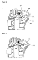
- Fig. 10 shows, in cross-sectional view, the state where the lower operation button is pressed in.
- the latch part 214 and the projection 241a are unlatched and the contact 229a is pressed in toward the resistor 224a as much as the amount of rotation of the contact piece 242a at the contact position. Consequently, the conductive member 223a and the resistor 224a come into contact with each other, and the resistor 224a outputs an analog signal according to the contact area.
- Fig. 11 shows, in cross-sectional view, the state where the lower operation button is pressed in by the maximum amount of rotation.
- the projecting part 240a is in contact with the outer periphery of the case, thereby limiting the rotating operation.
- the contact area between the conductive member 223a and the resistor 224a is at its maximum, and the resistor 224a outputs the maximum analog signal.
- Fig. 12 shows the rotating structure of the lower operation button.
- the lower operation button 230a is formed as a box, having the following four sides: the surface 234a; the rear which includes the peripheral area 237a; and the two sidewalls 238 which are continuous with the surface 234a and the rear.
- the contact piece 242a is attached inside the box of the lower operation button 230.
- the rotation shaft 232a is inserted through the shaft holes which are formed in the sidewalls 238 of the lower operation button 230a.
- the spring member 243a is attached to the rotation shaft 232a.
- a single spring member 243a may be used as shown in the diagram. Alternatively, two spring members 243a may be provided across the bearing part of the contact piece 242a.
- the rotation shaft 232a is pivotally mounted in hole portions of the holder member 225a. Each hole portion has a diameter capable of accommodating the rotation shaft 232a, and has an opening which is made slightly smaller than the diameter of the rotation shaft 232a. The rotation shaft 232a can thus be fit into and supported by the holder members 225a.
- the lower operation button 230a is rotatably attached to the internal substrate 225.
- the internal substrate 225 has a flat part 225b for the elastic body 222 (not shown) to be placed on.
- the flat part 225b supports one end of the spring member 243a. It should be appreciated that the other end of the spring member 243a is supported by the bottom of the contact piece 242a.
- the internal substrate 225 is common between the lower operation button 230a and the upper operation button 220a, though not shown in the diagram.
- the left side of the internal substrate 225 is thus provided with a structure for attaching the upper operation button 220a.
- Fig. 13 shows the rotating structure of the lower operation button from the bottom.
- Parallel guides 231 for attaching and fixing the contact piece 242a are formed on both the sidewalls inside the lower operation button 230a. Both the sides of the plate part of the contact piece 242a are inserted into the parallel guides 231.
- the contact piece 242a has the contact surface 233 which makes contact with the contact 229a of the elastic body 222.
- the contact surface 233 is formed flat and at a given angle to the bottom area of the contact piece itself so that the contact 229a of the elastic body 222 is located in a predetermined position with respect to the resistor 224a before being pressed. This predetermined position is determined so as to allow an appropriate amount of play. As a result, a desired analog output can be obtained by a rotating operation on the lower operation button 230a.
Landscapes
- Engineering & Computer Science (AREA)
- Multimedia (AREA)
- Human Computer Interaction (AREA)
- General Engineering & Computer Science (AREA)
- Theoretical Computer Science (AREA)
- Physics & Mathematics (AREA)
- General Physics & Mathematics (AREA)
- Push-Button Switches (AREA)
- Position Input By Displaying (AREA)
- Adjustable Resistors (AREA)
- Rotary Switch, Piano Key Switch, And Lever Switch (AREA)
- Switches With Compound Operations (AREA)
Applications Claiming Priority (1)
| Application Number | Priority Date | Filing Date | Title |
|---|---|---|---|
| JP2006128746A JP4386900B2 (ja) | 2006-05-02 | 2006-05-02 | 操作装置およびゲームコントローラ |
Publications (2)
| Publication Number | Publication Date |
|---|---|
| EP1852162A1 true EP1852162A1 (fr) | 2007-11-07 |
| EP1852162B1 EP1852162B1 (fr) | 2011-06-08 |
Family
ID=38190832
Family Applications (1)
| Application Number | Title | Priority Date | Filing Date |
|---|---|---|---|
| EP07251805A Active EP1852162B1 (fr) | 2006-05-02 | 2007-04-30 | Dispositif de commande et contrôleur de jeu |
Country Status (5)
| Country | Link |
|---|---|
| US (1) | US8115588B2 (fr) |
| EP (1) | EP1852162B1 (fr) |
| JP (1) | JP4386900B2 (fr) |
| CN (1) | CN100514258C (fr) |
| AT (1) | ATE511896T1 (fr) |
Cited By (32)
| Publication number | Priority date | Publication date | Assignee | Title |
|---|---|---|---|---|
| CN102974099A (zh) * | 2011-12-09 | 2013-03-20 | 微软公司 | 多级可变阻力板机 |
| EP2698185A4 (fr) * | 2012-04-20 | 2015-10-07 | Nintendo Co Ltd | Unité de commande de jeu |
| WO2017089820A3 (fr) * | 2015-11-27 | 2017-07-13 | Ironburg Inventions Limited | Manette de jeu et élément déclencheur s'y rapportant |
| EP3254737A1 (fr) * | 2016-06-10 | 2017-12-13 | Nintendo Co., Ltd. | Contrôleur de jeu |
| EP3254735A1 (fr) * | 2016-06-10 | 2017-12-13 | Nintendo Co., Ltd. | Contrôleur de jeu |
| US10029175B2 (en) | 2013-11-29 | 2018-07-24 | Ironburg Inventions Ltd. | Controller for a games console |
| US10188940B2 (en) | 2013-11-29 | 2019-01-29 | Ironburg Inventions Ltd. | Games controller |
| US10258877B2 (en) | 2014-01-22 | 2019-04-16 | Ironburg Inventions Limited | Games controller |
| US10279250B2 (en) | 2013-07-10 | 2019-05-07 | Ironburg Inventions Ltd. | Games controller and trigger therefor |
| US10350490B2 (en) | 2016-06-14 | 2019-07-16 | Ironburg Inventions Limited | Games controller |
| US10427036B2 (en) | 2015-09-24 | 2019-10-01 | Ironburg Inventions Limited | Games controller |
| US10441881B2 (en) | 2015-01-09 | 2019-10-15 | Ironburg Inventions Limited | Controller for a games console |
| US10441878B2 (en) | 2016-06-10 | 2019-10-15 | Nintendo Co., Ltd. | Game controller |
| US10456669B2 (en) | 2016-06-10 | 2019-10-29 | Nintendo Co., Ltd. | Game controller |
| US10576386B2 (en) | 2015-09-23 | 2020-03-03 | Ironburg Inventions Limited | Games controller |
| US10596453B2 (en) | 2014-02-05 | 2020-03-24 | Ironburg Inventions Limited | Controller for a games console, tool and a method therefor |
| USD881283S1 (en) | 2018-09-05 | 2020-04-14 | Ironburg Inventions Limited | Game controller |
| USD881282S1 (en) | 2018-09-05 | 2020-04-14 | Ironburg Inventions Limited | Game controller |
| USD881125S1 (en) | 2018-09-05 | 2020-04-14 | Ironburg Inventions Limited | Game controller motor set |
| USD889549S1 (en) | 2018-09-05 | 2020-07-07 | Ironburg Inventions Limited | Game controller |
| USD889550S1 (en) | 2018-09-05 | 2020-07-07 | Ironburg Inventions Limited | Game controller |
| US10835811B2 (en) | 2016-06-10 | 2020-11-17 | Nintendo Co., Ltd. | Game controller |
| US10843069B2 (en) | 2016-08-11 | 2020-11-24 | Ironburg Inventions Limited | Input apparatus for a computer |
| US10864436B2 (en) | 2016-06-10 | 2020-12-15 | Nintendo Co., Ltd. | Game controller |
| US10870051B2 (en) | 2014-05-12 | 2020-12-22 | Ironburg Inventions Limited | Games controller |
| US10940386B2 (en) | 2015-10-09 | 2021-03-09 | Ironburg Inventions Limited | Games controller |
| US11013986B2 (en) | 2017-03-15 | 2021-05-25 | Ironburg Inventions Limited | Input apparatus for a games console |
| US11103775B2 (en) | 2017-06-12 | 2021-08-31 | Ironburg Inventions Limited | Input apparatus for a games console |
| USD983269S1 (en) | 2020-06-19 | 2023-04-11 | Ironburg Inventions Limited | Input apparatus for a games console |
| CN116510283A (zh) * | 2023-05-17 | 2023-08-01 | 广州市品众电子科技有限公司 | 一种游戏手柄 |
| US12420208B2 (en) | 2020-06-19 | 2025-09-23 | Ironburg Inventions Limited | Input apparatus for a games console |
| US12478865B2 (en) | 2021-01-11 | 2025-11-25 | Ironburg Inventions Limited | Input apparatus for a games console |
Families Citing this family (27)
| Publication number | Priority date | Publication date | Assignee | Title |
|---|---|---|---|---|
| JP4386900B2 (ja) * | 2006-05-02 | 2009-12-16 | アルプス電気株式会社 | 操作装置およびゲームコントローラ |
| WO2010019937A1 (fr) * | 2008-08-15 | 2010-02-18 | Mattel, Inc. | Jouet électronique et procédés d’interaction avec ce dernier |
| US8267787B2 (en) | 2009-01-16 | 2012-09-18 | Sony Computer Entertainment Inc. | Controller and portable electronic apparatus |
| JP4890571B2 (ja) * | 2009-01-16 | 2012-03-07 | 株式会社ソニー・コンピュータエンタテインメント | 操作装置及び携帯情報端末 |
| US8674935B2 (en) * | 2009-10-21 | 2014-03-18 | Qualcomm Incorporated | System delay mitigation in interactive systems |
| JP5837325B2 (ja) * | 2010-11-01 | 2015-12-24 | 任天堂株式会社 | 操作装置および操作システム |
| JP5161338B2 (ja) | 2011-05-09 | 2013-03-13 | 株式会社ソニー・コンピュータエンタテインメント | キーボード |
| JP2012096005A (ja) * | 2011-08-01 | 2012-05-24 | Nintendo Co Ltd | 表示装置、ゲームシステム、およびゲーム処理方法 |
| JP5392863B2 (ja) | 2011-09-05 | 2014-01-22 | 任天堂株式会社 | 周辺装置、情報処理システム、および、周辺装置の接続方法 |
| US8747197B2 (en) * | 2012-05-09 | 2014-06-10 | Bradley Morris | Handheld electronic device for entering activity of sporting event by multiple parties having party scores |
| CN104667525B (zh) * | 2013-11-29 | 2020-08-04 | 艾朗博格发明有限公司 | 游戏控制器 |
| US10446344B2 (en) | 2015-05-27 | 2019-10-15 | Microsoft Technology Licensing, Llc | Hair trigger travel stop with on-demand switching |
| JP6412533B2 (ja) * | 2016-10-06 | 2018-10-24 | 任天堂株式会社 | 周辺装置、情報処理システム、および、周辺装置の接続方法 |
| JP6518881B2 (ja) * | 2016-10-28 | 2019-05-29 | 積水ポリマテック株式会社 | 押釦スイッチ用弾性部材および押釦スイッチ |
| US10668371B2 (en) | 2016-12-16 | 2020-06-02 | Razer (Asia-Pacific) Pte. Ltd. | Game controllers |
| EP3740292A2 (fr) * | 2018-04-02 | 2020-11-25 | Google LLC | Dispositif d'entrée pour système électronique |
| JP6517403B1 (ja) * | 2018-05-25 | 2019-05-22 | 任天堂株式会社 | ゲームコントローラ |
| JP6499354B1 (ja) * | 2018-05-25 | 2019-04-10 | 任天堂株式会社 | ゲームコントローラ |
| US10843070B2 (en) | 2018-05-25 | 2020-11-24 | Nintendo Co., Ltd. | Game controller |
| EP3822745B1 (fr) * | 2018-07-12 | 2024-06-05 | Sony Interactive Entertainment Inc. | Système de traitement d'informations et procédé de fonctionnement de celui-ci |
| US10814222B2 (en) | 2018-09-21 | 2020-10-27 | Logitech Europe S.A. | Gaming controller with adaptable input configurations |
| CN112206506B (zh) * | 2019-07-11 | 2025-07-15 | 深圳市壹位堂科技有限公司 | 一种扳机键及游戏手柄 |
| JP6751808B1 (ja) * | 2019-09-13 | 2020-09-09 | アルスコーポレーション株式会社 | 剪定用電動切断装置 |
| TWI801252B (zh) * | 2022-05-30 | 2023-05-01 | 融程電訊股份有限公司 | 具有不同顏色之按鍵的無線電對講機的按鍵結構及其製造方法 |
| US12263399B2 (en) | 2022-10-17 | 2025-04-01 | Ironburg Inventions Limited | Optical user input device |
| US20250058212A1 (en) * | 2023-08-18 | 2025-02-20 | Shenzhen Jierui Hong Electronics Co., LTD | Button module and game controller with the button module |
| WO2026028405A1 (fr) * | 2024-08-01 | 2026-02-05 | 任天堂株式会社 | Dispositif |
Citations (5)
| Publication number | Priority date | Publication date | Assignee | Title |
|---|---|---|---|---|
| US20010023203A1 (en) * | 1999-12-16 | 2001-09-20 | Cheng Chiu-Hao | Button control for use in a game controller |
| US6352477B1 (en) * | 1999-07-27 | 2002-03-05 | Alps Electric Co., Ltd. | Signal input device applicable to controllers for game machines |
| US20020190528A1 (en) * | 1999-01-21 | 2002-12-19 | Yasuhiro Ootori | Resistance force generator for use in a gaming machine |
| EP1493471A2 (fr) * | 1999-09-11 | 2005-01-05 | Sony Computer Entertainment Inc. | Appareil de commande et dipositif de détection |
| EP1498804A1 (fr) * | 2003-07-18 | 2005-01-19 | Alps Electric Co., Ltd. | Dispositif de introduction analogue |
Family Cites Families (19)
| Publication number | Priority date | Publication date | Assignee | Title |
|---|---|---|---|---|
| JPS5862525A (ja) | 1981-10-09 | 1983-04-14 | Shimadzu Corp | 電子天びん |
| JPS58170731A (ja) | 1982-03-31 | 1983-10-07 | Mitsui Toatsu Chem Inc | アクリル酸又はメタアクリル酸エステルの製造法 |
| JPS58201213A (ja) * | 1982-05-19 | 1983-11-24 | 松下電器産業株式会社 | ビデオテ−プレコ−ダ用パルススイツチ |
| JPS595842A (ja) | 1982-07-01 | 1984-01-12 | Mitsubishi Electric Corp | 内燃機関の燃料制御装置 |
| JP2602198B2 (ja) | 1984-10-15 | 1997-04-23 | 三井東圧化学株式会社 | ポリイミド樹脂粉末からなる耐熱性接着剤 |
| JPH02278623A (ja) | 1989-04-18 | 1990-11-14 | Sekisui Chem Co Ltd | 押ボタンスイッチ装置 |
| JPH0361304A (ja) | 1989-07-27 | 1991-03-18 | Nkk Corp | 複合材料の製造方法 |
| JP3219354B2 (ja) | 1994-08-26 | 2001-10-15 | アルプス電気株式会社 | 多方向入力装置 |
| SE515262C2 (sv) * | 1995-02-16 | 2001-07-09 | Abb Research Ltd | Anordning för strömbegränsning och skydd mot kortslutningsströmmar i en elektrisk anläggning |
| JPH09171742A (ja) | 1995-12-19 | 1997-06-30 | Taito Corp | コントローラの方向制御キー |
| JPH10118337A (ja) | 1996-10-21 | 1998-05-12 | Mitsumi Electric Co Ltd | コンピュータゲーム機用コントロールパッドのシフトレバーキー |
| JP3453263B2 (ja) | 1996-11-11 | 2003-10-06 | 任天堂株式会社 | ゲーム機用操作装置 |
| JP3388719B2 (ja) | 1999-09-10 | 2003-03-24 | ホシデン株式会社 | トリガ型入力装置 |
| JP2002318658A (ja) | 1999-09-11 | 2002-10-31 | Sony Computer Entertainment Inc | 操作装置および検出素子 |
| JP2002182851A (ja) | 2000-12-15 | 2002-06-28 | Nagano Fujitsu Component Kk | スクロール操作装置及びこれを有するマウス |
| WO2002035566A2 (fr) * | 2002-02-15 | 2002-05-02 | Phonak Ag | Commutateur a bascule tournante |
| JP3941603B2 (ja) * | 2002-06-25 | 2007-07-04 | 松下電器産業株式会社 | 回転型エンコーダ |
| JP4386900B2 (ja) * | 2006-05-02 | 2009-12-16 | アルプス電気株式会社 | 操作装置およびゲームコントローラ |
| DK2095384T3 (en) * | 2006-12-13 | 2016-07-04 | Sonova Ag | Switching element for activating an adjustable parameter |
-
2006
- 2006-05-02 JP JP2006128746A patent/JP4386900B2/ja not_active Expired - Lifetime
-
2007
- 2007-04-27 US US11/796,601 patent/US8115588B2/en active Active
- 2007-04-30 AT AT07251805T patent/ATE511896T1/de not_active IP Right Cessation
- 2007-04-30 EP EP07251805A patent/EP1852162B1/fr active Active
- 2007-05-08 CN CNB2007101024107A patent/CN100514258C/zh active Active
Patent Citations (5)
| Publication number | Priority date | Publication date | Assignee | Title |
|---|---|---|---|---|
| US20020190528A1 (en) * | 1999-01-21 | 2002-12-19 | Yasuhiro Ootori | Resistance force generator for use in a gaming machine |
| US6352477B1 (en) * | 1999-07-27 | 2002-03-05 | Alps Electric Co., Ltd. | Signal input device applicable to controllers for game machines |
| EP1493471A2 (fr) * | 1999-09-11 | 2005-01-05 | Sony Computer Entertainment Inc. | Appareil de commande et dipositif de détection |
| US20010023203A1 (en) * | 1999-12-16 | 2001-09-20 | Cheng Chiu-Hao | Button control for use in a game controller |
| EP1498804A1 (fr) * | 2003-07-18 | 2005-01-19 | Alps Electric Co., Ltd. | Dispositif de introduction analogue |
Cited By (46)
| Publication number | Priority date | Publication date | Assignee | Title |
|---|---|---|---|---|
| CN102974099A (zh) * | 2011-12-09 | 2013-03-20 | 微软公司 | 多级可变阻力板机 |
| US8894491B2 (en) | 2011-12-09 | 2014-11-25 | Microsoft Corporation | Multi-stage variable resistance trigger |
| CN102974099B (zh) * | 2011-12-09 | 2015-06-17 | 微软公司 | 多级可变阻力板机 |
| EP2698185A4 (fr) * | 2012-04-20 | 2015-10-07 | Nintendo Co Ltd | Unité de commande de jeu |
| US9517407B2 (en) | 2012-04-20 | 2016-12-13 | Nintendo Co., Ltd. | Game system and game controller |
| US10279250B2 (en) | 2013-07-10 | 2019-05-07 | Ironburg Inventions Ltd. | Games controller and trigger therefor |
| US10029175B2 (en) | 2013-11-29 | 2018-07-24 | Ironburg Inventions Ltd. | Controller for a games console |
| US10188940B2 (en) | 2013-11-29 | 2019-01-29 | Ironburg Inventions Ltd. | Games controller |
| US11185766B2 (en) | 2013-11-29 | 2021-11-30 | Ironburg Inventions Limited | Games controller |
| US10596455B2 (en) | 2013-11-29 | 2020-03-24 | Ironburg Inventions Ltd. | Games controller |
| US10258877B2 (en) | 2014-01-22 | 2019-04-16 | Ironburg Inventions Limited | Games controller |
| US10596453B2 (en) | 2014-02-05 | 2020-03-24 | Ironburg Inventions Limited | Controller for a games console, tool and a method therefor |
| US10870051B2 (en) | 2014-05-12 | 2020-12-22 | Ironburg Inventions Limited | Games controller |
| US11110345B2 (en) | 2015-01-09 | 2021-09-07 | Ironburg Inventions Limited | Controller for a games console |
| US10441881B2 (en) | 2015-01-09 | 2019-10-15 | Ironburg Inventions Limited | Controller for a games console |
| US10576386B2 (en) | 2015-09-23 | 2020-03-03 | Ironburg Inventions Limited | Games controller |
| US10427036B2 (en) | 2015-09-24 | 2019-10-01 | Ironburg Inventions Limited | Games controller |
| US10940386B2 (en) | 2015-10-09 | 2021-03-09 | Ironburg Inventions Limited | Games controller |
| US10220308B2 (en) | 2015-11-27 | 2019-03-05 | Ironburg Inventions Ltd. | Games controller and trigger therefor |
| WO2017089820A3 (fr) * | 2015-11-27 | 2017-07-13 | Ironburg Inventions Limited | Manette de jeu et élément déclencheur s'y rapportant |
| US11400365B2 (en) | 2016-06-10 | 2022-08-02 | Nintendo Co., Ltd. | Game controller |
| US11826641B2 (en) | 2016-06-10 | 2023-11-28 | Nintendo Co., Ltd. | Game controller |
| US10286306B2 (en) | 2016-06-10 | 2019-05-14 | Nintendo Co., Ltd. | Game controller |
| US10456669B2 (en) | 2016-06-10 | 2019-10-29 | Nintendo Co., Ltd. | Game controller |
| US12246248B2 (en) | 2016-06-10 | 2025-03-11 | Nintendo Co., Ltd. | Game controller |
| EP3254735A1 (fr) * | 2016-06-10 | 2017-12-13 | Nintendo Co., Ltd. | Contrôleur de jeu |
| EP3372288A1 (fr) * | 2016-06-10 | 2018-09-12 | Nintendo Co., Ltd. | Commande de jeu |
| US10441878B2 (en) | 2016-06-10 | 2019-10-15 | Nintendo Co., Ltd. | Game controller |
| EP3254737A1 (fr) * | 2016-06-10 | 2017-12-13 | Nintendo Co., Ltd. | Contrôleur de jeu |
| US10835811B2 (en) | 2016-06-10 | 2020-11-17 | Nintendo Co., Ltd. | Game controller |
| US11224800B2 (en) | 2016-06-10 | 2022-01-18 | Nintendo Co., Ltd. | Game controller |
| US10864436B2 (en) | 2016-06-10 | 2020-12-15 | Nintendo Co., Ltd. | Game controller |
| US10335675B2 (en) | 2016-06-10 | 2019-07-02 | Nintendo Co., Ltd. | Game controller |
| US10350490B2 (en) | 2016-06-14 | 2019-07-16 | Ironburg Inventions Limited | Games controller |
| US10843069B2 (en) | 2016-08-11 | 2020-11-24 | Ironburg Inventions Limited | Input apparatus for a computer |
| US11013986B2 (en) | 2017-03-15 | 2021-05-25 | Ironburg Inventions Limited | Input apparatus for a games console |
| US11103775B2 (en) | 2017-06-12 | 2021-08-31 | Ironburg Inventions Limited | Input apparatus for a games console |
| USD889550S1 (en) | 2018-09-05 | 2020-07-07 | Ironburg Inventions Limited | Game controller |
| USD889549S1 (en) | 2018-09-05 | 2020-07-07 | Ironburg Inventions Limited | Game controller |
| USD881125S1 (en) | 2018-09-05 | 2020-04-14 | Ironburg Inventions Limited | Game controller motor set |
| USD881282S1 (en) | 2018-09-05 | 2020-04-14 | Ironburg Inventions Limited | Game controller |
| USD881283S1 (en) | 2018-09-05 | 2020-04-14 | Ironburg Inventions Limited | Game controller |
| USD983269S1 (en) | 2020-06-19 | 2023-04-11 | Ironburg Inventions Limited | Input apparatus for a games console |
| US12420208B2 (en) | 2020-06-19 | 2025-09-23 | Ironburg Inventions Limited | Input apparatus for a games console |
| US12478865B2 (en) | 2021-01-11 | 2025-11-25 | Ironburg Inventions Limited | Input apparatus for a games console |
| CN116510283A (zh) * | 2023-05-17 | 2023-08-01 | 广州市品众电子科技有限公司 | 一种游戏手柄 |
Also Published As
| Publication number | Publication date |
|---|---|
| JP4386900B2 (ja) | 2009-12-16 |
| CN100514258C (zh) | 2009-07-15 |
| CN101067764A (zh) | 2007-11-07 |
| ATE511896T1 (de) | 2011-06-15 |
| US8115588B2 (en) | 2012-02-14 |
| JP2007299706A (ja) | 2007-11-15 |
| US20070281787A1 (en) | 2007-12-06 |
| EP1852162B1 (fr) | 2011-06-08 |
Similar Documents
| Publication | Publication Date | Title |
|---|---|---|
| EP1852162B1 (fr) | Dispositif de commande et contrôleur de jeu | |
| US7580728B2 (en) | Universal mobile gaming docking station and controller | |
| US11294485B2 (en) | Sensor fusion algorithms for a handheld controller that includes a force sensing resistor (FSR) | |
| JP2026004303A (ja) | センサリッチ制御装置を有するコントローラ | |
| CN1950132B (zh) | 电子装置及游戏控制器 | |
| US20180272232A1 (en) | Force sensing resistor (fsr) with polyimide substrate, systems, and methods thereof | |
| US20180056180A1 (en) | Controller having accessory connectors for externalizing controls | |
| CN108472542A (zh) | 游戏控制器及为此的触发器 | |
| US10649583B1 (en) | Sensor fusion algorithms for a handheld controller that includes a force sensing resistor (FSR) | |
| US11033811B2 (en) | Controller and cover member | |
| US12370436B2 (en) | Hand-held controller | |
| JP4142061B2 (ja) | ゲームコントローラ | |
| CN211273522U (zh) | 外接控制器 | |
| WO2011034174A1 (fr) | Dispositif de commande | |
| EP3793699B1 (fr) | Algorithmes de fusion de capteur pour un dispositif de commande portatif qui comprend une résistance de détection de force (fsr) | |
| CN112219246B (zh) | 具有聚酰亚胺衬底的力感测电阻器(fsr)、系统和其方法 | |
| KR200401975Y1 (ko) | 컴퓨터 제어장치 | |
| CN215232070U (zh) | 游戏手柄 | |
| EP3915001B1 (fr) | Algorithmes de fusion de capteur pour un dispositif de commande portatif qui comprend une résistance de détection de force (fsr) | |
| JP7690703B1 (ja) | ゲームコントローラ | |
| US20260102694A1 (en) | Game controller | |
| HK40129114A (zh) | 游戏控制器 | |
| CN112437910B (zh) | 用于握住和释放虚拟对象的方法和系统 | |
| WO2024161461A1 (fr) | Dispositif de commande | |
| KR100893820B1 (ko) | 전자 장치 및 게임 제어기 |
Legal Events
| Date | Code | Title | Description |
|---|---|---|---|
| PUAI | Public reference made under article 153(3) epc to a published international application that has entered the european phase |
Free format text: ORIGINAL CODE: 0009012 |
|
| 17P | Request for examination filed |
Effective date: 20070525 |
|
| AK | Designated contracting states |
Kind code of ref document: A1 Designated state(s): AT BE BG CH CY CZ DE DK EE ES FI FR GB GR HU IE IS IT LI LT LU LV MC MT NL PL PT RO SE SI SK TR |
|
| AX | Request for extension of the european patent |
Extension state: AL BA HR MK YU |
|
| 17Q | First examination report despatched |
Effective date: 20080409 |
|
| AKX | Designation fees paid |
Designated state(s): AT BE BG CH CY CZ DE DK EE ES FI FR GB GR HU IE IS IT LI LT LU LV MC MT NL PL PT RO SE SI SK TR |
|
| GRAP | Despatch of communication of intention to grant a patent |
Free format text: ORIGINAL CODE: EPIDOSNIGR1 |
|
| GRAC | Information related to communication of intention to grant a patent modified |
Free format text: ORIGINAL CODE: EPIDOSCIGR1 |
|
| GRAS | Grant fee paid |
Free format text: ORIGINAL CODE: EPIDOSNIGR3 |
|
| GRAA | (expected) grant |
Free format text: ORIGINAL CODE: 0009210 |
|
| AK | Designated contracting states |
Kind code of ref document: B1 Designated state(s): AT BE BG CH CY CZ DE DK EE ES FI FR GB GR HU IE IS IT LI LT LU LV MC MT NL PL PT RO SE SI SK TR |
|
| REG | Reference to a national code |
Ref country code: GB Ref legal event code: FG4D |
|
| REG | Reference to a national code |
Ref country code: CH Ref legal event code: EP |
|
| REG | Reference to a national code |
Ref country code: IE Ref legal event code: FG4D |
|
| REG | Reference to a national code |
Ref country code: DE Ref legal event code: R096 Ref document number: 602007015016 Country of ref document: DE Effective date: 20110721 |
|
| REG | Reference to a national code |
Ref country code: NL Ref legal event code: T3 |
|
| PG25 | Lapsed in a contracting state [announced via postgrant information from national office to epo] |
Ref country code: SE Free format text: LAPSE BECAUSE OF FAILURE TO SUBMIT A TRANSLATION OF THE DESCRIPTION OR TO PAY THE FEE WITHIN THE PRESCRIBED TIME-LIMIT Effective date: 20110608 Ref country code: LT Free format text: LAPSE BECAUSE OF FAILURE TO SUBMIT A TRANSLATION OF THE DESCRIPTION OR TO PAY THE FEE WITHIN THE PRESCRIBED TIME-LIMIT Effective date: 20110608 |
|
| PG25 | Lapsed in a contracting state [announced via postgrant information from national office to epo] |
Ref country code: AT Free format text: LAPSE BECAUSE OF FAILURE TO SUBMIT A TRANSLATION OF THE DESCRIPTION OR TO PAY THE FEE WITHIN THE PRESCRIBED TIME-LIMIT Effective date: 20110608 Ref country code: FI Free format text: LAPSE BECAUSE OF FAILURE TO SUBMIT A TRANSLATION OF THE DESCRIPTION OR TO PAY THE FEE WITHIN THE PRESCRIBED TIME-LIMIT Effective date: 20110608 Ref country code: SI Free format text: LAPSE BECAUSE OF FAILURE TO SUBMIT A TRANSLATION OF THE DESCRIPTION OR TO PAY THE FEE WITHIN THE PRESCRIBED TIME-LIMIT Effective date: 20110608 Ref country code: LV Free format text: LAPSE BECAUSE OF FAILURE TO SUBMIT A TRANSLATION OF THE DESCRIPTION OR TO PAY THE FEE WITHIN THE PRESCRIBED TIME-LIMIT Effective date: 20110608 Ref country code: GR Free format text: LAPSE BECAUSE OF FAILURE TO SUBMIT A TRANSLATION OF THE DESCRIPTION OR TO PAY THE FEE WITHIN THE PRESCRIBED TIME-LIMIT Effective date: 20110909 Ref country code: CY Free format text: LAPSE BECAUSE OF FAILURE TO SUBMIT A TRANSLATION OF THE DESCRIPTION OR TO PAY THE FEE WITHIN THE PRESCRIBED TIME-LIMIT Effective date: 20110608 Ref country code: ES Free format text: LAPSE BECAUSE OF FAILURE TO SUBMIT A TRANSLATION OF THE DESCRIPTION OR TO PAY THE FEE WITHIN THE PRESCRIBED TIME-LIMIT Effective date: 20110919 |
|
| PG25 | Lapsed in a contracting state [announced via postgrant information from national office to epo] |
Ref country code: BE Free format text: LAPSE BECAUSE OF FAILURE TO SUBMIT A TRANSLATION OF THE DESCRIPTION OR TO PAY THE FEE WITHIN THE PRESCRIBED TIME-LIMIT Effective date: 20110608 |
|
| PG25 | Lapsed in a contracting state [announced via postgrant information from national office to epo] |
Ref country code: EE Free format text: LAPSE BECAUSE OF FAILURE TO SUBMIT A TRANSLATION OF THE DESCRIPTION OR TO PAY THE FEE WITHIN THE PRESCRIBED TIME-LIMIT Effective date: 20110608 Ref country code: IS Free format text: LAPSE BECAUSE OF FAILURE TO SUBMIT A TRANSLATION OF THE DESCRIPTION OR TO PAY THE FEE WITHIN THE PRESCRIBED TIME-LIMIT Effective date: 20111008 Ref country code: CZ Free format text: LAPSE BECAUSE OF FAILURE TO SUBMIT A TRANSLATION OF THE DESCRIPTION OR TO PAY THE FEE WITHIN THE PRESCRIBED TIME-LIMIT Effective date: 20110608 Ref country code: PT Free format text: LAPSE BECAUSE OF FAILURE TO SUBMIT A TRANSLATION OF THE DESCRIPTION OR TO PAY THE FEE WITHIN THE PRESCRIBED TIME-LIMIT Effective date: 20111010 |
|
| PG25 | Lapsed in a contracting state [announced via postgrant information from national office to epo] |
Ref country code: PL Free format text: LAPSE BECAUSE OF FAILURE TO SUBMIT A TRANSLATION OF THE DESCRIPTION OR TO PAY THE FEE WITHIN THE PRESCRIBED TIME-LIMIT Effective date: 20110608 Ref country code: SK Free format text: LAPSE BECAUSE OF FAILURE TO SUBMIT A TRANSLATION OF THE DESCRIPTION OR TO PAY THE FEE WITHIN THE PRESCRIBED TIME-LIMIT Effective date: 20110608 Ref country code: RO Free format text: LAPSE BECAUSE OF FAILURE TO SUBMIT A TRANSLATION OF THE DESCRIPTION OR TO PAY THE FEE WITHIN THE PRESCRIBED TIME-LIMIT Effective date: 20110608 |
|
| PLBE | No opposition filed within time limit |
Free format text: ORIGINAL CODE: 0009261 |
|
| STAA | Information on the status of an ep patent application or granted ep patent |
Free format text: STATUS: NO OPPOSITION FILED WITHIN TIME LIMIT |
|
| 26N | No opposition filed |
Effective date: 20120309 |
|
| PG25 | Lapsed in a contracting state [announced via postgrant information from national office to epo] |
Ref country code: IT Free format text: LAPSE BECAUSE OF FAILURE TO SUBMIT A TRANSLATION OF THE DESCRIPTION OR TO PAY THE FEE WITHIN THE PRESCRIBED TIME-LIMIT Effective date: 20110608 |
|
| PG25 | Lapsed in a contracting state [announced via postgrant information from national office to epo] |
Ref country code: DK Free format text: LAPSE BECAUSE OF FAILURE TO SUBMIT A TRANSLATION OF THE DESCRIPTION OR TO PAY THE FEE WITHIN THE PRESCRIBED TIME-LIMIT Effective date: 20110608 |
|
| REG | Reference to a national code |
Ref country code: DE Ref legal event code: R097 Ref document number: 602007015016 Country of ref document: DE Effective date: 20120309 |
|
| PG25 | Lapsed in a contracting state [announced via postgrant information from national office to epo] |
Ref country code: MC Free format text: LAPSE BECAUSE OF NON-PAYMENT OF DUE FEES Effective date: 20120430 |
|
| REG | Reference to a national code |
Ref country code: CH Ref legal event code: PL |
|
| PG25 | Lapsed in a contracting state [announced via postgrant information from national office to epo] |
Ref country code: LI Free format text: LAPSE BECAUSE OF NON-PAYMENT OF DUE FEES Effective date: 20120430 Ref country code: CH Free format text: LAPSE BECAUSE OF NON-PAYMENT OF DUE FEES Effective date: 20120430 |
|
| PG25 | Lapsed in a contracting state [announced via postgrant information from national office to epo] |
Ref country code: IE Free format text: LAPSE BECAUSE OF NON-PAYMENT OF DUE FEES Effective date: 20120430 |
|
| PG25 | Lapsed in a contracting state [announced via postgrant information from national office to epo] |
Ref country code: BG Free format text: LAPSE BECAUSE OF FAILURE TO SUBMIT A TRANSLATION OF THE DESCRIPTION OR TO PAY THE FEE WITHIN THE PRESCRIBED TIME-LIMIT Effective date: 20110908 |
|
| PG25 | Lapsed in a contracting state [announced via postgrant information from national office to epo] |
Ref country code: MT Free format text: LAPSE BECAUSE OF FAILURE TO SUBMIT A TRANSLATION OF THE DESCRIPTION OR TO PAY THE FEE WITHIN THE PRESCRIBED TIME-LIMIT Effective date: 20110608 |
|
| PG25 | Lapsed in a contracting state [announced via postgrant information from national office to epo] |
Ref country code: TR Free format text: LAPSE BECAUSE OF FAILURE TO SUBMIT A TRANSLATION OF THE DESCRIPTION OR TO PAY THE FEE WITHIN THE PRESCRIBED TIME-LIMIT Effective date: 20110608 |
|
| PG25 | Lapsed in a contracting state [announced via postgrant information from national office to epo] |
Ref country code: LU Free format text: LAPSE BECAUSE OF NON-PAYMENT OF DUE FEES Effective date: 20120430 |
|
| PG25 | Lapsed in a contracting state [announced via postgrant information from national office to epo] |
Ref country code: HU Free format text: LAPSE BECAUSE OF FAILURE TO SUBMIT A TRANSLATION OF THE DESCRIPTION OR TO PAY THE FEE WITHIN THE PRESCRIBED TIME-LIMIT Effective date: 20070430 |
|
| REG | Reference to a national code |
Ref country code: FR Ref legal event code: PLFP Year of fee payment: 10 |
|
| REG | Reference to a national code |
Ref country code: FR Ref legal event code: PLFP Year of fee payment: 11 |
|
| REG | Reference to a national code |
Ref country code: FR Ref legal event code: PLFP Year of fee payment: 12 |
|
| REG | Reference to a national code |
Ref country code: NL Ref legal event code: HC Owner name: ALPS ALPINE CO., LTD.; JP Free format text: DETAILS ASSIGNMENT: CHANGE OF OWNER(S), CHANGE OF OWNER(S) NAME; FORMER OWNER NAME: SONY COMPUTER ENTERTAINMENT INC. Effective date: 20190204 |
|
| PGFP | Annual fee paid to national office [announced via postgrant information from national office to epo] |
Ref country code: DE Payment date: 20250319 Year of fee payment: 19 |
|
| PGFP | Annual fee paid to national office [announced via postgrant information from national office to epo] |
Ref country code: GB Payment date: 20260319 Year of fee payment: 20 |
|
| PGFP | Annual fee paid to national office [announced via postgrant information from national office to epo] |
Ref country code: NL Payment date: 20260319 Year of fee payment: 20 |
|
| PGFP | Annual fee paid to national office [announced via postgrant information from national office to epo] |
Ref country code: FR Payment date: 20260320 Year of fee payment: 20 |