EP1853480B1 - Unite d'entrainement marine - Google Patents
Unite d'entrainement marine Download PDFInfo
- Publication number
- EP1853480B1 EP1853480B1 EP06740976A EP06740976A EP1853480B1 EP 1853480 B1 EP1853480 B1 EP 1853480B1 EP 06740976 A EP06740976 A EP 06740976A EP 06740976 A EP06740976 A EP 06740976A EP 1853480 B1 EP1853480 B1 EP 1853480B1
- Authority
- EP
- European Patent Office
- Prior art keywords
- clutch
- shaft
- stern drive
- fairing
- transverse shaft
- Prior art date
- Legal status (The legal status is an assumption and is not a legal conclusion. Google has not performed a legal analysis and makes no representation as to the accuracy of the status listed.)
- Expired - Lifetime
Links
Images






Classifications
-
- B—PERFORMING OPERATIONS; TRANSPORTING
- B63—SHIPS OR OTHER WATERBORNE VESSELS; RELATED EQUIPMENT
- B63H—MARINE PROPULSION OR STEERING
- B63H20/00—Outboard propulsion units, e.g. outboard motors or Z-drives; Arrangements thereof on vessels
- B63H20/14—Transmission between propulsion power unit and propulsion element
- B63H20/22—Transmission between propulsion power unit and propulsion element allowing movement of the propulsion element about at least a horizontal axis without disconnection of the drive, e.g. using universal joints
-
- B—PERFORMING OPERATIONS; TRANSPORTING
- B63—SHIPS OR OTHER WATERBORNE VESSELS; RELATED EQUIPMENT
- B63H—MARINE PROPULSION OR STEERING
- B63H5/00—Arrangements on vessels of propulsion elements directly acting on water
- B63H5/07—Arrangements on vessels of propulsion elements directly acting on water of propellers
- B63H5/125—Arrangements on vessels of propulsion elements directly acting on water of propellers movably mounted with respect to hull, e.g. adjustable in direction, e.g. podded azimuthing thrusters
- B63H5/1252—Arrangements on vessels of propulsion elements directly acting on water of propellers movably mounted with respect to hull, e.g. adjustable in direction, e.g. podded azimuthing thrusters the ability to move being conferred by gearing in transmission between prime mover and propeller and the propulsion unit being other than in a "Z" configuration
-
- B—PERFORMING OPERATIONS; TRANSPORTING
- B63—SHIPS OR OTHER WATERBORNE VESSELS; RELATED EQUIPMENT
- B63H—MARINE PROPULSION OR STEERING
- B63H20/00—Outboard propulsion units, e.g. outboard motors or Z-drives; Arrangements thereof on vessels
- B63H20/14—Transmission between propulsion power unit and propulsion element
- B63H20/20—Transmission between propulsion power unit and propulsion element with provision for reverse drive
-
- B—PERFORMING OPERATIONS; TRANSPORTING
- B63—SHIPS OR OTHER WATERBORNE VESSELS; RELATED EQUIPMENT
- B63H—MARINE PROPULSION OR STEERING
- B63H20/00—Outboard propulsion units, e.g. outboard motors or Z-drives; Arrangements thereof on vessels
- B63H20/32—Housings
- B63H20/34—Housings comprising stabilising fins, foils, anticavitation plates, splash plates, or rudders
Definitions
- THIS INVENTION relates to marine drives.
- Marine drives can conveniently be classified into three categories.
- a technical complexity which has to be dealt with in a stern drive results from two factors. Firstly, the fairing must be able rotate about a vertical, or substantially vertical, axis so as to direct the propeller's thrust at an angle to the front-to-rear line thereby to permit steering. Secondly, it must be possible to "trim" the fairing, which means tilting the fairing about a horizontal axis to change its pitch. This directs the propeller's thrust either horizontally or at a desired angle with respect to horizontal. This movement is also used for the purpose of raising the fairing so that the boat can be loaded on a trailer or run onto a shore.
- United States specification 6,186,845 discloses a stern drive which permits the steering motion of the fairing and also the tilting motion of the fairing which is needed to adjust the fairing's pitch and permit it to be raised to enable the boat to be placed on a trailer.
- PCT specification WO 2004/085245 discloses another form of stern drive. Without in any way attempting to provide an exhaustive list, other forms of stern drive are disclosed in United States specifications 6,468,119 , 5,601,464 , 4,037,558 , 3,847,108 and 3,166,040 , with the closest prior art being constituted by US 4 276 034 .
- Conventional stern drives are based on layouts in which the crank shaft of the engine drives an output shaft through a universal joint, or more usually two universal joints. Constant velocity joints have been proposed as substitutes for universal joints.
- the output shaft is horizontal, or substantially horizontal, and drives a gear set, the output shaft of which is vertical or substantially vertical.
- the vertical output shaft drives a lower gear set which in turn drives the propeller shaft.
- a gimbel which carries the motor and which is mounted on a fixed part of the boat.
- the gimbel is usually mounted for motion about a vertical, or near vertical, axis.
- a steering arm is connected to the gimbel.
- the mounting of the fairing on the gimbel is about a generally horizontal axis. By tilting the fairing about this horizontal axis with respect to the gimbel using one or more rams, the fairing can be trimmed up or down and lifted for stowage.
- crank shaft and the horizontal output shaft permit these shafts to move relative to one another as the fairing moves with the gimbel (about a vertical steering axis) and with respect to the gimbel (about a horizontal trim axis).
- the gimbel is mounted on the boat for movement, with the fairing, about a horizontal axis to enable the fairing to be trimmed.
- the fairing is mounted on the gimbel for movement with respect to the gimbel about a vertical axis.
- the steering arm displaces the fairing with respect to the gimbel about this vertical axis for steering purposes.
- the gear set of conventional stern drives as described above can include a first bevel pinion driven from the crank shaft of the motor, first and second bevel gears meshing with the first bevel pinion and being rotated in opposite directions, a reversing clutch for connecting the first bevel gear or the second bevel gear to a first transverse shaft.
- the first transverse shaft will thus rotate in opposite directions, depending on whether the first or the second bevel gear are connected to it. The rotation of the first transverse shaft is transferred to the output shaft.
- the first and second bevel gears are coaxially carried on the first transverse shaft on opposite sides of the first bevel pinion and the clutch is thus used to connect either the first or the second bevel gear to the first transverse shaft in order to change the rotational direction of the output shaft between a forward and a reverse condition.
- Each of the first and second bevel gears can have a protruding part that defines a conical clutch face and the clutch can include a clutch element, connected to the first transverse shaft with helical splines, between the first and second bevel gears.
- the clutch element can be connected to either the first or the second bevel gear, by sliding axially on the first transverse shaft and engaging the conical clutch face of one of the bevel gears.
- the helical splines are oriented so that, if the clutch element is connected to one of the first or the second bevel gears and transfers torque from the bevel gear to the first transverse shaft, the clutch element is drawn into engagement with the particular bevel gear by the interaction between the clutch element and the splines.
- the result is that the clutch keeps itself in engagement, while torque is being transferred and little force is required to engage it.
- the force that is required to overcome the self engaging spline action and thus to disengage the clutch can be quite high.
- the mechanism by which the clutch element is shifted on the first transverse shaft thus has to be capable of effecting substantial axial forces on the clutch element.
- the clutch is conventionally operated by sliding the clutch element on the first transverse shaft, with a fork-shaped selector, engaging the clutch element in a circumferential shifting groove.
- selectors of this type that obviously have to be clear of the bevel gears, require space, which comes at a premium in these gear sets and the spacial requirements of these selectors inhibit the development of compact new types of stern drives.
- the gearset is aft of the transom and the hydrodynamics of the marine drive can be severely affected by the size of the gear set, the gearbox casing, the cylindrical housing, etc.
- the main object of the present invention is to provide an improved stern drive, preferably including an improved reversing clutch.
- a stern drive which comprises:
- the axis of rotation of the housing relative to the outer structure may extend at an inclined angle.
- Said gear set and reversing clutch may comprise:
- the fairing may be displaced by a ram the cylinder of which forms part of said housing and the rod of which may be connected to a structure which forms an extension of said fairing.
- Said output shaft may drive a pinion which meshes with a gear on a further output shaft that is parallel to the first mentioned output shaft, the output shafts driving co-axial propeller shafts and the arrangement being such that the output shafts rotate in opposite directions and the propeller shafts also contra-rotate.
- the stern drive may include a third output shaft, driven from the pinion.
- the third output shaft may have a gear that meshes with the pinion or with the gear of the second output shaft.
- Said fairing may comprise a pair of side sections which are attached together, and a top section which is attached to the side sections.
- the output shaft may be in an elongate casing which extends upwardly from said fairing and which may itself be extended by a pivot structure to which said rod is connected.
- the pivot structure may be mounted on said second transverse shaft and may rotate about it during lifting and lowering of the fairing and during trimming.
- the first transverse shaft may define helical splines with which the clutch element is in engagement and the transverse shaft may define a central passage that extends axially form at least one of its ends and defines at least one internal recess that extends in a radial direction.
- the stern drive may further include a selector rod, disposed coaxially within the central passage of the transverse shaft and being axially slidable within the central passage and at least one selector pin extending transversely form the selector rod, at least one slot being defined in the transverse shaft, extending from the central passage to the outside of the shaft and having an orientation that is generally aligned with the helical splines of the shaft, the selector pin extending from the selector rod, through the slot and into the internal recess defined in the clutch element.
- the reversing clutch may include two selector pins extending in diametrically opposing directions from the selector rod, each passing through a separate slot and into a separate internal recess of the clutch element.
- Each internal recess in the clutch element may extend to an outer circumference of the clutch element and each selector pin may be held captive within its internal recess, by a retaining element such as a circlip.
- the clutch may include a diaphragm, connected to a plunger which is configured to effect axial displacement of the selector rod and the diaphragm may be disposed adjacent the end of the transverse shaft from which the central passage extends.
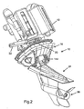
- the stern drive 10 shown in Figures 1 to 6 of the drawings comprises a motor 12 which is mounted on the inclined transom 14 of the boat.
- the structure 16 which mounts the stern drive in an opening 18 provided therefor in the transom 14 is partly within the boat and partly outside the boat.
- a steering arm is shown at 20 and the steering cylinder which is connected to the arm is shown at 22.
- the fairing of the stern drive is designated 24. It is mounted for pivoting motion about a horizontal axis. It is also mounted for motion about a steering axis as will be described in more detail hereinafter.
- a bevel gear 26 in the lowermost part of the fairing 24 and a propeller shaft driven by the gear 26 is shown at 28.
- the shaft 28 passes through a sleeve 30 within which bearings 32 for the shaft 28 are mounted.
- a further bearing is shown at 34.
- the propeller is shown at 36 and is secured by a nut 38 to the shaft 28.
- the structure 16 is hollow and constructed so that it can house two bearings and seals 40 and 42 which mount a gear set and clutch housing 44.
- the steering arm 20 is connected to the housing 44 and oscillates the housing 44 for steering purposes as will be described hereinafter.
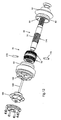
- a gear set and reversing clutch are shown at 46 in Figures 5 and 6 and are illustrated in more detail in Figure 8 , with elements of the clutch shown in more detail in Figures 10 to 12 .
- the gear set and reversing clutch 46 are inside the housing 44.
- Figure 8 the seal of the bearing and seal 42 is shown. The bearing is above the seal but has not been illustrated.
- An input shaft 48 has an array of splines (not shown) which enables it to be secured to the crank shaft (not shown) of the motor 12.
- the shaft 48 rotates in bearings 52 and 54 which are mounted in a bearing sleeve 56 which is bolted to the housing 44.
- a nut 58 secures the bearings 52,54 to the shaft 48 and a shaft seal is shown at 60.
- the sleeve 56 is externally splined and the arm 20 is connected to this.
- the housing 44 comprises two outer shells 44.1, 44.2 of semi-cylindrical form and a centre part 44.3.
- a first bevel pinion 62 is integral with the input shaft 48.
- a first bevel gear 64 and a second bevel gear 66 are supported coaxially on a first transverse shaft 68, with the first and second bevel gears 64,66 meshing with the first bevel pinion 62 on opposing sides.
- the first and second bevel gears 64,66 are supported on the first transverse shaft 68 on bearings 70 and it is to be understood that the first and second bevel gears will counter rotate, irrespective of the motion of the first transverse shaft.
- External bearings 72 are provided for mounting the first and second bevel gears 64,66 in the centre part 44.3 of the housing assembly 44.
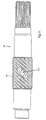
- the first transverse shaft 68 has helical splines 74 defined along its centre portion, the first transverse shaft passing through a sleeve-like clutch element 76.
- the clutch element 76 has complemental internal helical splines.
- the clutch element 76 has external, conical clutch surfaces 78, which co-operate with complemental internal conical clutch surfaces 80 defined in protuberances 82 of the first and second bevel gears 64,66, respectively.
- the clutch element 76 can slide helically on the helical splines of the first transverse shaft 68, so that one of its clutch surfaces 78 engages the corresponding clutch surface 80 of either the first bevel gear 64 or the second bevel gear 66. Once engaged, the clutch element 76, by virtue of the interaction between the helical splines, pulls itself into the engaged position.
- the clutch assembly is thus configured to connect the first bevel gear 64 to the first transverse shaft 68 via the clutch element 76 in a reverse condition, to connect the second bevel gear 66 to the first transverse shaft 68 in a forward condition and to connect neither the first nor the second bevel gear to the first transverse shaft, in a neutral condition, or vice versa.
- a helical pinion 84 is keyed onto the first transverse shaft 68 and rotates in bearings 86.
- the pinion 84 meshes with a similarly mounted helical gear 88 which is keyed to a second transverse shaft 90.
- a second bevel pinion 92 is secured to the second transverse shaft 90 and meshes with a third bevel gear 94 forming part of an output shaft 96, which rotates in bearings 98 that are mounted in a bearing housing 100.
- the bearing housing 100 is within a pivot structure that is designated 146.
- a circlip 148 holds the housing 104 in the structure 146.
- the output shaft 96 defines internal splines, which allows it to be connected to an externally splined inclined shaft 106 with a bevel pinion 110 at its lower end, that meshes with the gear 26 to drive the propeller 36.
- the left hand side of the housing 44 is configured to receive another set of a helical pinion and gear.
- FIG. 10 details of the clutch assembly 102, forming part of the gear set and reversing clutch 46, includes a selector rod 168 that is coaxially slidable within a central passage 170 that is defined inside the first transverse shaft 68, from its end opposite from the end driving the pinion 84, i.e. from the left hand side in the drawings.
- Two selector pins 172 extend transversely in diametrically opposing directions from the selector rod 168, close to its right hand end.
- the selector pins 172 are in the form of hollow pins and each have a protuberance that is slidably received in a circumferential slot in the selector rod 168. In this embodiment, the selector rod 168 can rotate relative to the selector pins 172.
- the selector pins 172 could be in the form of a single pin that extends through a transverse aperture in the selector rod. In this embodiment, the selector rod 168 and selector pins 172 rotate together.
- Each slot 174 has a width generally equal to the diameter of the selector pins 172 and is generally aligned with the helical splines 74.
- radial apertures 176 Two internal recesses in the form of radial apertures 176 are defined in the clutch element 76 and are diametrically opposed and coaxial. The diameter of each of the apertures 176 is generally equal to the outer diameter of the selector pins 172.
- the selector pins 172 extend from the selector rod 168 through the slots 174 into the apertures 176, where they fit snugly. Accordingly, if the selector rod 168 slides axially within the central passage, the selector pins 172 slide in the slots 174 and move the clutch element 76 axially. It would be clear to those skilled in the art that the movements of the selector pins 172 and clutch element 76 relative to the first transverse shaft, are not purely axial, but helical, since the selector pins slide in the slots 174 and the clutch element slides on the helical splines 74. The helical movement of the clutch element 76 allows its clutch surfaces 78 to engage and disengage the clutch surfaces 80 as described above.
- the selector pins 172 are held captive in their positions by retaining elements (not shown) such as circlips in the outer ends of the apertures 176 or a retaining spring that extends around the circumference of the clutch element, in a circumferential groove 178.
- retaining elements such as circlips in the outer ends of the apertures 176 or a retaining spring that extends around the circumference of the clutch element, in a circumferential groove 178.
- the clutch 102 can be actuated in a number of ways, to impart axial movement to the selector rod 168.
- the clutch includes a diaphragm 180 housed in a chamber 182 in which it can be displaced to the left or the right by applying hydraulic pressure within the chamber on either side of the diaphragm.
- the diaphragm 180 is connected to the selector rod 168 in a transverse arrangement and it follows that displacement of the diaphragm causes axial displacement the selector rod and thus operates the clutch as described above.
- the selector rod can be connected to the diaphragm 180 via bearings, to slide rotatably within this attachment.
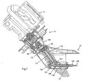
- the stern drive of Figure 7 differs from that of Figures 1 to 6 in that the shaft 96 drives a pinion 112 which is at the upper end of a first inclined output shaft 114.
- the pinion 112 meshes with a gear 116 at the upper end of a second inclined shaft 118.
- the shafts 114, 118 have bevel pinions 120, 122 at the lower ends thereof. These bevel pinions mesh with further bevel gears 124, 126 on two contrarotating propeller shafts 128, 130.
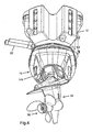
- the fairing 24 (see particularly Figure 9 ) comprises two side sections 132, 134 and an upper section 136.
- the lower parts of the sections 132, 134 are generally semi-cylindrical and receive the propeller shaft 28 (or propeller shafts 128, 130). More specifically, the sleeve 30 is part of a tube 138 which is closed at its front end (see Figures 5 , 6 and 7 ) and houses the bearing 34.
- the two semi-cylindrical parts of the sections 132, 134 house the tube 138.
- the sections 132, 134 have horizontal webs 140 at their upper ends, these being secured to the section 136 during fabrication of the fairing.
- the inclined shaft 106 (or the inclined shafts 114, 118) are within an inclined elongate casing 142 which is clamped between the sections 132, 134 during fabrication.
- the structure 146 has two opposing cylindrical ends 150, each of which extends around a cylindrical protuberance 152 of its corresponding part of the housing 44.2 and 44.3 with bearings 154 between the cylindrical ends and protuberances, all co-axial with the shaft 90.
- the pivot structure 146 can rotate about the axis of the shaft 90 carrying the housing 100 and shaft 96 with it.
- the gear 94 "rolls around" the pinion 92.
- the casing 142 is secured by bolts (not shown) to the lower end of the structure 146.
- a shell 144 which is purely aesthetic is provided to conceal the internal structure.
- An arm 158 forming part of the pivot structure 146 is connected by a link 160 to the rod 162 of a ram 164.
- the cylinder 166 of the ram 164 is part of the housing 44.
- rams There are two further rams (not shown) parallel to the ram 164. These rams are of shorter stroke than the ram 164. All three rams are used to displace the fairing 24 for trimming purposes, the force required being significant in view of the thrust exerted on the fairing by the propeller 36. During lifting of the fairing 24 for stowage purposes, all three rams are operated. Two, however, reach the end of their travel before stowage is completed, and the ram 164 is effective to finalize such lifting.
- the fairing 24 thus moves between its raised and lowered positions by rotating about an axis which is the axis of the shaft 90.
- the fairing is shown displaced to the position it occupies during a turn to port.
Landscapes
- Chemical & Material Sciences (AREA)
- Engineering & Computer Science (AREA)
- Combustion & Propulsion (AREA)
- Mechanical Engineering (AREA)
- Ocean & Marine Engineering (AREA)
- Gear Transmission (AREA)
- Mechanical Operated Clutches (AREA)
- Air-Conditioning For Vehicles (AREA)
- Vehicle Body Suspensions (AREA)
- Lubrication Of Internal Combustion Engines (AREA)
- Structure Of Transmissions (AREA)
Claims (20)
- Propulseur azimutal (10) qui comprend une structure externe (16) qui peut être fixée à la poupe (14) d'un bateau ; un boîtier (44) supporté dans la structure externe (16), le boîtier (44) peut tourner à l'intérieur de la structure externe (16) dans des sens de direction ;
un ensemble d'engrenages et un inverseur (46) étant adaptés pour recevoir la puissance de rotation, autour d'un axe de sortie, d'une source de puissance (12) et pour transférer la puissance à un arbre de sortie (96, 106), ledit ensemble d'engrenages comprenant un pignon (92) peut tourner autour d'un axe transversal (90) ; et ledit arbre de sortie (96, 106) s'étend vers le bas à l'intérieur d'un carénage (24) ;
caractérisé en ce que ledit ensemble d'engrenages et l'inverseur (46) sont à l'intérieur dudit boîtier (44) et en ce que le carénage (24) et l'arbre de sortie (96, 106) peuvent tourner autour de l'axe transversal (90) dudit pignon (92) pour permettre ainsi le levage, l'abaissement et l'équilibrage du carénage (24). - Propulseur azimutal (10) selon la revendication 1, caractérisé en ce que le boîtier (44) peut tourner dans lesdits sens de direction à l'intérieur de la structure externe (16) autour de l'axe d'entrée.
- Propulseur azimutal (10) selon la revendication 1 ou la revendication 2, caractérisé en ce que ledit propulseur azimutal comprend une structure de pivot (146) pour faire pivoter ledit carénage (24) et l'arbre de sortie (96, 106) par rapport au boîtier (44) autour de l'axe transversal (90) dans les directions de levage /abaissement / équilibre.
- Propulseur azimutal (10) selon l'une quelconque des revendications précédentes, caractérisé en ce que l'axe de rotation du boîtier (44) par rapport à la structure externe (16), s'étend au niveau d'un angle incliné.
- Propulseur azimutal (10) selon l'une quelconque des revendications précédentes, caractérisé en ce que ledit arbre de sortie (96, 114) entraîne un pignon (112) qui s'engrène avec un engrenage (116) sur un autre arbre de sortie (118) qui est parallèle au premier arbre de sortie mentionné, les arbres de sortie entraînant des arbres de propulseur coaxiaux (128, 130), l'agencement étant tel que les arbres de sortie tournent dans des directions opposées et les arbres de propulseur tournent également à contre-sens.
- Propulseur azimutal (10) selon la revendication 5, caractérisé en ce que le propulseur azimutal comprend un troisième arbre de sortie, entraîné par le pignon (112).
- Propulseur azimutal (10) selon l'une quelconque des revendications précédentes, caractérisé en ce que ledit carénage (24) comprend deux sections latérales (132, 134) qui sont fixées ensemble, et une section supérieure (136) qui est fixée sur les sections latérales.
- Propulseur azimutal (10) selon l'une quelconque des revendications précédentes, caractérisé en ce que le carénage (24) est déplacé par un vérin (164), dont le cylindre (166) fait partie dudit boîtier (44) et dont la tige (162) est raccordée à une structure (158, 160) qui forme une extension dudit carénage (24).
- Propulseur azimutal (10) selon la revendication 8, caractérisé en ce que l'arbre de sortie (106) est dans un carter allongé (142) qui s'étend vers le haut à partir dudit carénage (24) et qui est lui-même étendu par une structure de pivot (146) à laquelle ladite tige (162) est raccordée.
- Propulseur azimutal (10) selon la revendication 9, caractérisé en ce que la structure de pivot (46) est montée sur ledit deuxième arbre transversal (90) et tourne autour de ce dernier pendant le levage et l'abaissement du carénage (24) et pendant l'équilibrage.
- Propulseur azimutal (10) selon l'une quelconque des revendications précédentes, caractérisé en ce que ledit ensemble d'engrenages et l'inverseur (46) comprennent un premier pignon conique (62) pouvant être raccordé à un moteur (12) ; des premier et second engrenages coniques (64, 66) qui s'engrènent avec le premier pignon conique sur les côtés diamétralement opposés du pignon conique et qui sont coaxiaux, chacun des engrenages coniques définissant une face d'embrayage conique (80) ; un premier arbre transversal (68) passant de manière coaxiale à travers les engrenages coniques ; un élément d'embrayage (76) disposé sur l'arbre transversal entre les engrenages coniques, ledit élément d'embrayage définissant deux surfaces coniques (78), dont chacune est complémentaire de la face d'embrayage de l'un des engrenages coniques ; un pignon hélicoïdal (84) sur ledit premier arbre transversal ; un engrenage hélicoïdal (88) s'engrenant avec ledit pignon hélicoïdal et supporté par un deuxième arbre transversal (90) ; et un second pignon conique (92) supporté par le deuxième arbre transversal et s'engrenant avec un troisième engrenage conique (94) supporté par ledit arbre de sortie (96), ledit carénage (24) tournant autour de l'axe du deuxième arbre transversal pendant le levage, l'abaissement et l'équilibrage du carénage.
- Propulseur azimutal (10) selon la revendication 11, dans lequel le premier arbre transversal (68) définit des cannelures hélicoïdales (74) avec lesquelles l'élément d'embrayage (76) est en mise en prise, l'arbre transversal définit un passage central (170) qui s'étend de manière axiale à partir d'au moins l'une de ses extrémités et l'élément d'embrayage définit au moins un évidement interne (176) et s'étend dans une direction radiale, caractérisé en ce que le propulseur azimutal comprend en outre une tige de sélecteur (168), disposée de manière coaxiale à l'intérieur du passage central (170) de l'arbre transversal et pouvant coulisser de manière axiale à l'intérieur du passage central et au moins une broche de sélecteur (172) s'étendant de manière transversale à partir de la tige de sélecteur, au moins une fente (174) étant définie dans l'arbre transversal, s'étendant à partir du passage central jusqu'à l'extérieur de l'arbre et ayant une orientation qui est généralement alignée avec les cannelures hélicoïdales de l'arbre, la broche de sélecteur s'étendant à partir de la tige de sélecteur, en passant par la fente et dans l'évidement interne défini dans l'élément d'embrayage.
- Propulseur azimutal (10) selon la revendication 12, caractérisé en ce que l'inverseur (102) comprend deux broches de sélecteur (172) s'étendant dans des directions diamétralement opposées à partir de la tige de sélecteur (168), chacune passant par une fente séparée (174) et dans un évidement interne séparé (176) de l'élément d'embrayage (76).
- Propulseur azimutal (10) selon la revendication 13, caractérisé en ce que chaque évidement interne (176) dans l'élément d'embrayage (76) s'étend sur une circonférence externe de l'élément d'embrayage et chaque broche de sélecteur (172) est maintenue captive à l'intérieur de son évidement interne par un élément de retenue.
- Propulseur azimutal (10) selon la revendication 12, caractérisé en ce que l'embrayage (102) comprend un diaphragme (180) raccordé à un piston plongeur qui est configuré pour effectuer le déplacement axial de la tige de sélecteur (168).
- Propulseur azimutal (10) selon la revendication 15, caractérisé en ce que le diaphragme (180) est disposé de manière adjacente à l'extrémité de l'arbre transversal (68) à partir de laquelle le passage central (170) s'étend.
- Propulseur azimutal (10) selon l'une quelconque des revendications précédentes, caractérisé en ce que ledit propulseur comprend un arbre d'entrée (48) à partir duquel ledit ensemble d'engrenages et l'inverseur (46) sont adaptés pour recevoir la puissance de rotation autour dudit axe d'entrée à partir d'une source de puissance (12).
- Propulseur azimutal (10) selon l'une quelconque des revendications précédentes, caractérisé en ce que ledit propulseur comprend une structure de direction (20, 22) pour faire tourner ledit boîtier (44) à l'intérieur de ladite structure externe (16) dans lesdits sens de direction.
- Propulseur azimutal (10) selon l'une quelconque des revendications précédentes, caractérisé en ce que ladite structure externe (16) peut être fixée sur un tableau arrière (14) dudit bateau.
- Propulseur azimutal (10) selon l'une quelconque des revendications précédentes, caractérisé en ce que ledit propulseur comprend un moteur (12) qui peut fonctionner pour transmettre ladite puissance de rotation autour dudit axe d'entrée audit ensemble d'engrenages et à l'inverseur (46).
Priority Applications (1)
| Application Number | Priority Date | Filing Date | Title |
|---|---|---|---|
| EP08168752A EP2058224A2 (fr) | 2005-02-18 | 2006-02-20 | Propulseur marin |
Applications Claiming Priority (3)
| Application Number | Priority Date | Filing Date | Title |
|---|---|---|---|
| ZA200501448 | 2005-02-18 | ||
| ZA200508874 | 2005-11-02 | ||
| PCT/ZA2006/000027 WO2006089316A1 (fr) | 2005-02-18 | 2006-02-20 | Unite d'entrainement marine |
Related Child Applications (2)
| Application Number | Title | Priority Date | Filing Date |
|---|---|---|---|
| EP08168752A Division EP2058224A2 (fr) | 2005-02-18 | 2006-02-20 | Propulseur marin |
| EP08168752.7 Division-Into | 2008-11-10 |
Publications (2)
| Publication Number | Publication Date |
|---|---|
| EP1853480A1 EP1853480A1 (fr) | 2007-11-14 |
| EP1853480B1 true EP1853480B1 (fr) | 2010-06-30 |
Family
ID=36579587
Family Applications (2)
| Application Number | Title | Priority Date | Filing Date |
|---|---|---|---|
| EP08168752A Withdrawn EP2058224A2 (fr) | 2005-02-18 | 2006-02-20 | Propulseur marin |
| EP06740976A Expired - Lifetime EP1853480B1 (fr) | 2005-02-18 | 2006-02-20 | Unite d'entrainement marine |
Family Applications Before (1)
| Application Number | Title | Priority Date | Filing Date |
|---|---|---|---|
| EP08168752A Withdrawn EP2058224A2 (fr) | 2005-02-18 | 2006-02-20 | Propulseur marin |
Country Status (10)
| Country | Link |
|---|---|
| US (2) | US7588473B2 (fr) |
| EP (2) | EP2058224A2 (fr) |
| JP (1) | JP4658149B2 (fr) |
| KR (1) | KR100956859B1 (fr) |
| AT (1) | ATE472470T1 (fr) |
| AU (1) | AU2006214025B2 (fr) |
| CA (1) | CA2598035C (fr) |
| DE (1) | DE602006015167D1 (fr) |
| NZ (1) | NZ560379A (fr) |
| WO (1) | WO2006089316A1 (fr) |
Families Citing this family (24)
| Publication number | Priority date | Publication date | Assignee | Title |
|---|---|---|---|---|
| EP2718178B1 (fr) * | 2011-06-10 | 2020-11-18 | Caudwell Marine Limited | Éléments propulsifs pour navires |
| US8550864B2 (en) | 2011-06-22 | 2013-10-08 | Michael Alan Beachy Head | Drives for propulsion of marine vessels |
| GB201410476D0 (en) * | 2014-06-12 | 2014-07-30 | Beachy Head Michael A | Outboard motor |
| US9714071B2 (en) * | 2014-07-17 | 2017-07-25 | Caterpillar Inc. | Breakaway shaft |
| KR20160065392A (ko) | 2014-11-28 | 2016-06-09 | 동명대학교산학협력단 | Bldc모터를 적용한 선외 추진장치 |
| KR20160065399A (ko) | 2014-11-28 | 2016-06-09 | 동명대학교산학협력단 | 회전효율성을 위한 감속기를 포함하는 선외 추진장치 |
| US9896175B2 (en) | 2016-06-21 | 2018-02-20 | Robby Galletta Enterprises LLC | Outboard motor and methods of use thereof |
| US10442516B2 (en) | 2017-07-17 | 2019-10-15 | Mark Small | Marine propulsion system |
| KR102033314B1 (ko) | 2018-03-20 | 2019-10-21 | 주식회사 지오티 | 선외추진기용 동력전달이 상하, 좌우 이동 및 역회전이 가능한 기어박스 |
| CA185637S (en) * | 2018-07-12 | 2020-08-25 | Rolls Royce Ab | Pod with double fin |
| US12304607B1 (en) | 2018-10-26 | 2025-05-20 | Brunswick Corporation | Marine drives having steerable gearcase |
| US10800502B1 (en) * | 2018-10-26 | 2020-10-13 | Brunswick Corporation | Outboard motors having steerable lower gearcase |
| EP3757425B1 (fr) * | 2019-06-28 | 2022-05-11 | Kontopoulos, Leonidas Kyros | Élément de transmission et boîte de vitesses pour un système de transmission de puissance |
| AU2020304584A1 (en) * | 2019-06-28 | 2022-01-27 | Konstantinos Kontopoulos | Transmission element and gearbox for a power transmission system |
| US11358695B2 (en) | 2019-12-18 | 2022-06-14 | Leonidas Kyros Kontopoulos | Divided gear wheel for a power transmission system used in a marine engine |
| US11208190B1 (en) | 2020-06-23 | 2021-12-28 | Brunswick Corporation | Stern drives having breakaway lower gearcase |
| USD1026955S1 (en) | 2020-06-23 | 2024-05-14 | Brunswick Corporation | Stern drive |
| US11286028B1 (en) * | 2020-11-20 | 2022-03-29 | Platinum Marine Inc. | Watercraft adjustable shaft spacing apparatus and related method of operation |
| US12606289B2 (en) | 2022-03-28 | 2026-04-21 | Brunswick Corporation | Stern drives and methods of installing stern drives |
| US12545391B2 (en) | 2022-03-28 | 2026-02-10 | Brunswick Corporation | Stern drives and noise-vibration-harshness dampening assemblies for a stern drives |
| US12304609B2 (en) | 2022-03-28 | 2025-05-20 | Brunswick Corporation | Stern drives and transom bracket assemblies for stern drives providing vibration isolation |
| US12600450B2 (en) | 2022-03-28 | 2026-04-14 | Brunswick Corporation | Stern drives having steerable gearcase |
| US12539952B2 (en) | 2022-03-28 | 2026-02-03 | Brunswick Corporation | Marine drives having hydraulically actuated steerable gearcase |
| GB2624215A (en) * | 2022-11-10 | 2024-05-15 | Rad Propulsion Ltd | Motor |
Family Cites Families (129)
| Publication number | Priority date | Publication date | Assignee | Title |
|---|---|---|---|---|
| US2410609A (en) | 1943-07-17 | 1946-11-05 | Joseph S Pecker | Aircraft rotor wing construction |
| US2659444A (en) | 1949-06-21 | 1953-11-17 | Autogiro Co Of America | Molded aircraft sustaining rotor blade |
| US2917019A (en) | 1955-02-16 | 1959-12-15 | Fred C Krueger | Propeller housing attachments |
| US3028292A (en) | 1957-05-27 | 1962-04-03 | Parsons Corp | Method of manufacturing plastic rotor blades |
| US3093105A (en) | 1959-08-14 | 1963-06-11 | Loral Electronics Corp | Control arrangement for a submarine vessel |
| US3166040A (en) * | 1960-11-21 | 1965-01-19 | Borg Warner | Drive unit for boats |
| SE309729B (fr) | 1961-02-09 | 1969-03-31 | Knutsson K | |
| US3229935A (en) | 1962-12-06 | 1966-01-18 | August T Bellanca | Aircraft wing construction |
| GB1021730A (en) | 1963-10-14 | 1966-03-09 | Volvo Penta Ab | Improvements in or relating to reversing mechanisms |
| US3382839A (en) | 1965-02-16 | 1968-05-14 | Brunswick Corp | Through transom mounted drive unit for watercraft |
| US3447504A (en) | 1966-04-28 | 1969-06-03 | Outboard Marine Corp | Marine propulsion lower unit |
| US3452704A (en) | 1966-07-14 | 1969-07-01 | Outboard Marine Corp | Engine mounted on a gimbal-like frame |
| US3478620A (en) | 1967-10-06 | 1969-11-18 | Outboard Marine Corp | Marine propulsion unit with dual drive shafts and dual propeller shafts |
| US3520272A (en) | 1968-05-13 | 1970-07-14 | Floyd P Ellzey | Angle drive boat propulsion unit with shaft supported propeller assembly |
| US3505894A (en) | 1968-08-08 | 1970-04-14 | Henry T Halibrand | Reversible shaft transmission |
| DE1900710A1 (de) | 1969-01-08 | 1970-08-27 | Zahnradfabrik Friedrichshafen | Hebevorrichtung fuer Aussenbordantriebe |
| US3583357A (en) | 1969-04-01 | 1971-06-08 | Outboard Marine Corp | Side mount stern drive |
| US3765370A (en) | 1969-08-19 | 1973-10-16 | Outboard Marine Corp | Means for balancing the steering forces when moving in a reverse direction |
| US3626467A (en) | 1969-09-03 | 1971-12-07 | Dana Corp | Marine drive |
| US3779487A (en) | 1971-04-19 | 1973-12-18 | L Ashton | Light weight contoured load carrying structure |
| US3847108A (en) | 1971-05-03 | 1974-11-12 | W Shimanckas | Stern drive unit with bellows enclosed reversing transmission and universal coupling steering control |
| US4037558A (en) * | 1971-07-09 | 1977-07-26 | Enfield Industrial Engines Limited | Marine drive units |
| GB1382835A (en) * | 1971-07-09 | 1975-02-05 | Enfield Ind Engines Ltd | Marine drive units |
| US3768922A (en) | 1972-02-14 | 1973-10-30 | United Aircraft Corp | Rotor blade construction and method |
| USRE27826E (en) | 1972-06-12 | 1973-12-04 | Marine propulsion device | |
| US3939795A (en) | 1974-06-03 | 1976-02-24 | Rocka Arthur J | Outboard motor protective cover |
| US3946841A (en) | 1974-07-17 | 1976-03-30 | American Challenger Corporation | Shift mechanism for a marine clutch |
| US3923131A (en) | 1974-08-26 | 1975-12-02 | American Challenger Corp | Shift ring for a marine clutch |
| US3946698A (en) | 1974-08-29 | 1976-03-30 | American Challenger Corporation | Inboard-outboard drive for marine vessel |
| DE2461896A1 (de) | 1974-12-31 | 1976-07-08 | Bosch Gmbh Robert | Stelleinrichtung |
| US3977356A (en) | 1975-05-16 | 1976-08-31 | Outboard Marine Corporation | Stern drive unit and transmission therefor |
| US4050359A (en) | 1975-09-04 | 1977-09-27 | Brunswick Corporation | Hydraulic power trim and power tilt system supply |
| US3999502A (en) | 1975-09-04 | 1976-12-28 | Brunswick Corporation | Hydraulic power trim and power tilt system supply |
| US3955526A (en) | 1975-09-06 | 1976-05-11 | Brunswick Corporation | Cowl apparatus for outboard motors |
| US4086869A (en) | 1977-02-07 | 1978-05-02 | James Edward Woodruff | Boat trim adjusting apparatus |
| US4297097A (en) | 1978-02-23 | 1981-10-27 | Kiekhaefer Elmer Carl | Stern drive mechanism |
| JPS6050635B2 (ja) | 1978-06-02 | 1985-11-09 | 株式会社昭和製作所 | 船舶推進機のトリム・チルト装置 |
| US4276034A (en) * | 1979-04-27 | 1981-06-30 | Outboard Marine Corporation | Stern drive gear box and clutching arrangement |
| US4244454A (en) | 1979-04-30 | 1981-01-13 | Brunswick Corporation | Cone clutch |
| US4257506A (en) | 1979-04-30 | 1981-03-24 | Brunswick Corporation | Shifter linkage for a cone clutch |
| SE417075B (sv) | 1979-05-23 | 1981-02-23 | Volvo Penta Ab | Transmissionssystem for batmotorer |
| US4363629A (en) | 1980-09-02 | 1982-12-14 | Outboard Marine Corporation | Hydraulic system for outboard motor with sequentially operating tilt and trim means |
| US4408994A (en) | 1980-09-18 | 1983-10-11 | Outboard Marine Corporation | Transom mounted marine propulsion device with fore and aft crankshaft and power shaft |
| US4382796A (en) * | 1980-09-18 | 1983-05-10 | Outboard Marine Corporation | Transom mounted marine propulsion device with vertical crankshaft and tiltable lower unit and rudder |
| JPS5795295A (en) | 1980-12-03 | 1982-06-14 | Yamaha Motor Co Ltd | Tilting lock device of outboard engine |
| US4375181A (en) | 1981-01-21 | 1983-03-01 | Conway John P | Hydraulic cylinder extending in three force modes |
| SE433599B (sv) | 1981-03-05 | 1984-06-04 | Volvo Penta Ab | Dubbelpropellerdrev for batar |
| US4416637A (en) * | 1981-07-13 | 1983-11-22 | Outboard Marine Corporation | Marine steering mechanism and associated actuating and locking device |
| SE451191B (sv) | 1982-09-13 | 1987-09-14 | Volvo Penta Ab | Propellerdrev for batar |
| JPS59227593A (ja) * | 1983-06-08 | 1984-12-20 | Sanshin Ind Co Ltd | 船外機 |
| US5094081A (en) | 1983-07-21 | 1992-03-10 | Osborne Lyle E | Hydraulic brake system valved piston |
| JPS60116592A (ja) | 1983-11-29 | 1985-06-24 | Sanshin Ind Co Ltd | 船舶推進機のチルトロック装置 |
| US4666412A (en) | 1985-05-30 | 1987-05-19 | Outboard Marine Corporation | Marine engine mounting apparatus |
| US4630719A (en) | 1985-08-13 | 1986-12-23 | Brunswick Corporation | Torque aided pulsed impact shift mechanism |
| SE451572B (sv) | 1985-09-17 | 1987-10-19 | Volvo Penta Ab | Propellerkombination for ett batpropelleraggregat |
| USRE34011E (en) | 1985-09-17 | 1992-07-28 | Ab Volvo Penta | Propeller combination for a boat propeller unit |
| US4636175A (en) | 1985-11-07 | 1987-01-13 | Brunswick Corporation | Water inlet for outboard propulsion unit |
| US4850911A (en) | 1986-05-15 | 1989-07-25 | Sanshin Kogyo Kabushiki Kaisha | Power transmission device for inboard/outboard system |
| US4679682A (en) | 1986-08-18 | 1987-07-14 | Brunswick Corporation | Marine drive shift mechanism with detent canister centered neutral |
| US5108325A (en) | 1987-06-15 | 1992-04-28 | Brunswick Corporation | Boat propulsion device |
| JP2902403B2 (ja) | 1987-10-16 | 1999-06-07 | 三信工業株式会社 | 船舶用駆動ユニットのシフト装置 |
| US4972809A (en) | 1988-04-14 | 1990-11-27 | Sanshin Kogyo Kabushiki Kaisha | Power unit of inboard/outboard |
| US4869121A (en) | 1988-05-23 | 1989-09-26 | Brunswick Corporation | Marine propulsion unit with improved drive shaft arrangement |
| US4871334A (en) | 1988-08-04 | 1989-10-03 | Brunswick Corporation | Marine propulsion device with improved exhaust discharge |
| US4869693A (en) | 1988-08-24 | 1989-09-26 | Brunswick Corporation | Cowl and air inlet assembly |
| US4932907A (en) | 1988-10-04 | 1990-06-12 | Brunswick Corporation | Chain driven marine propulsion system with steerable gearcase and dual counterrotating propellers |
| US5009621A (en) | 1989-03-20 | 1991-04-23 | Brunswick Corporation | Torque splitting drive train mechanism for a dual counterrotating propeller marine drive system |
| IT1228764B (it) | 1989-03-29 | 1991-07-03 | Cesare Crispo | Trasmissione di potenza bilanciata e guidabile del tipo a "z" |
| GB2231853B (en) | 1989-04-12 | 1993-02-17 | Howlett Ian C | Rudder construction with integral stock |
| US4950188A (en) | 1989-05-12 | 1990-08-21 | Outboard Marine Corporation | Stern drive unit |
| US5006085A (en) | 1989-05-12 | 1991-04-09 | Outboard Marine Corporation | Marine propulsion device with removable clutch assembly |
| US4959033A (en) | 1989-05-12 | 1990-09-25 | Outboard Marine Corporation | Marine propulsion device cover arrangement |
| US5035664A (en) | 1989-05-12 | 1991-07-30 | Outboard Marine Corporation | Marine propulsion device gear arrangement |
| JPH0321588A (ja) * | 1989-06-19 | 1991-01-30 | Sanshin Ind Co Ltd | 2本のドライブ軸を備えた船舶推進機 |
| US4954109A (en) | 1989-07-20 | 1990-09-04 | Brunswick Corporation | Water pickup insert |
| NO170528C (no) | 1990-06-20 | 1992-10-28 | Jaico Marine As | Anordning ved innenbords/utenbords svingbart og oppsvingbart hekkaggregat for baat |
| US5059163A (en) | 1990-10-15 | 1991-10-22 | Von Greyerz John W | Trans-planetary mechanical torque impeller |
| JPH04185596A (ja) * | 1990-11-21 | 1992-07-02 | Nissan Kohki Co Ltd | 船外機,船内外機の推進軸におけるクラッチ機構 |
| SE467536B (sv) | 1990-12-03 | 1992-08-03 | Nixflu Ab | Anordning foer inriktning till olika vinkellaegen av en vattengaaende farkosts drivorgan |
| US5096034A (en) | 1991-03-15 | 1992-03-17 | Rotary Specialties | Reversing clutch mechanism |
| US5171177A (en) | 1991-06-27 | 1992-12-15 | Brunswick Corporation | Integrally formed driveshaft housing structure for interposition between the powerhead and lower unit of a marine propulsion system |
| SE469292B (sv) | 1991-09-12 | 1993-06-14 | Volvo Penta Ab | Transmissionsanordning i ett utombordsdrev foer baatar |
| US5425663A (en) | 1992-05-27 | 1995-06-20 | Brunswick Corporation | Counter-rotating surfacing marine drive with planing plate |
| US5462463A (en) | 1992-05-27 | 1995-10-31 | Brunswick Corporation | Marine dual propeller lower bore drive assembly |
| SE505502C2 (sv) | 1992-10-29 | 1997-09-08 | Volvo Penta Ab | Hydraulisk kolv- cylinderanordning |
| SE501269C2 (sv) * | 1993-05-05 | 1994-12-19 | Volvo Penta Ab | Transmissionsanordning, i synnerhet backslag för båtar |
| JP2826795B2 (ja) * | 1993-05-25 | 1998-11-18 | 本田技研工業株式会社 | 船舶推進機の駆動伝達装置 |
| US5407372A (en) | 1993-09-24 | 1995-04-18 | Outboard Marine Corporation | Outboard motor cover assembly |
| US5514014A (en) | 1993-10-04 | 1996-05-07 | Sanshin Kogyo Kabushiki Kaisha | Outboard drive transmission |
| SE501979C2 (sv) | 1993-11-03 | 1995-07-03 | Volvo Penta Ab | Backslag för båtar |
| US5597334A (en) | 1993-11-29 | 1997-01-28 | Sanshin Kogyo Kabushiki Kaisha | Outboard drive transmission system |
| JP3479941B2 (ja) | 1993-11-30 | 2003-12-15 | ヤマハマリン株式会社 | 船舶推進装置 |
| JP3413440B2 (ja) | 1994-05-31 | 2003-06-03 | ヤマハマリン株式会社 | 船舶推進装置 |
| US5487687A (en) | 1994-07-18 | 1996-01-30 | Brunswick Corporation | Midsection and cowl assembly for an outboard marine drive |
| US5476164A (en) | 1994-09-12 | 1995-12-19 | Regal-Beloit Corporation | Solenoid actuated mechanical clutch |
| AUPM842194A0 (en) | 1994-09-26 | 1994-10-20 | Larkin, Bryan James | Propulsion unit |
| JP3522390B2 (ja) | 1995-05-22 | 2004-04-26 | ヤマハマリン株式会社 | 二重反転プロペラ装置 |
| JP3541082B2 (ja) | 1995-06-05 | 2004-07-07 | ヤマハマリン株式会社 | 船舶推進装置 |
| SE504482C2 (sv) | 1995-06-26 | 1997-02-17 | Volvo Penta Ab | Transmissionsanordning, i synnerhet backslag för båtar |
| JP3716458B2 (ja) * | 1995-07-11 | 2005-11-16 | 石川島播磨重工業株式会社 | 全旋回式二重反転推進装置の潤滑機構 |
| US5964626A (en) | 1995-08-23 | 1999-10-12 | Outboard Marine Corporation | Tractor pump jet |
| JPH09315389A (ja) | 1996-05-30 | 1997-12-09 | Aisin Seiki Co Ltd | 船内外機の動力伝達装置 |
| US5766047A (en) | 1996-09-25 | 1998-06-16 | Brunswick Corporation | Twin propeller marine propulsion unit |
| US5791950A (en) | 1996-12-05 | 1998-08-11 | Brunswick Corporation | Twin propeller marine propulsion unit |
| US5829564A (en) | 1997-04-11 | 1998-11-03 | Brunswick Corporation | Marine drive shift mechanism with chamfered shift rings, stepped cams, and self-centering clutch |
| US5890938A (en) | 1997-10-02 | 1999-04-06 | Brunswick Corporation | Marine counter-rotational propulsion system |
| US6186845B1 (en) | 1998-01-28 | 2001-02-13 | Michael Alan Beachy Head | Motor mounting structure for boat |
| US5961358A (en) | 1998-03-16 | 1999-10-05 | Volvo Penta Of The Americas, Inc. | Reversible stern drive marine propulsion system |
| US6062360A (en) | 1998-05-13 | 2000-05-16 | Brunswick Corporation | Synchronizer for a gear shift mechanism for a marine propulsion system |
| JP2000062691A (ja) | 1998-08-25 | 2000-02-29 | Suzuki Motor Corp | 船外機のエンジンカバー取付構造 |
| SE513265C2 (sv) * | 1998-12-16 | 2000-08-14 | Volvo Penta Ab | Båtpropellertransmission |
| US6176170B1 (en) | 1999-03-03 | 2001-01-23 | Brunswick Corporation | Hydraulic actuator with shock absorbing capability |
| SE516579C2 (sv) | 1999-03-16 | 2002-01-29 | Volvo Penta Ab | Drivaggregat i en båt innefattande motroterande, dragande propellrar anordnade på ett undervattenshus och där akterpropellern arbetar kaviterande samt drivinstallation med två sådana drivaggregat |
| US6478641B2 (en) | 2000-01-20 | 2002-11-12 | W. Bishop Jordan | Transmission for driving counter-rotating propellers, lubrication system, and associated methods |
| US6609939B1 (en) | 2000-07-21 | 2003-08-26 | Bombardier Motor Corporation Of America | Marine engine mounting assembly |
| US6361387B1 (en) | 2001-01-19 | 2002-03-26 | Brunswick Corporation | Marine propulsion apparatus with dual driveshafts extending from a forward end of an engine |
| US6523655B1 (en) | 2001-09-10 | 2003-02-25 | Brunswick Corporation | Shift linkage for a marine drive unit |
| US6468120B1 (en) | 2001-11-12 | 2002-10-22 | Ab Volvo Penta | Single cylinder trim/tilt assembly |
| US6468119B1 (en) | 2001-11-12 | 2002-10-22 | Ab Volvo Penta | Composite stern drive assembly |
| JP3967147B2 (ja) | 2002-02-18 | 2007-08-29 | 創輝H・S株式会社 | 船外機用チルト装置 |
| SE523548C2 (sv) | 2002-06-25 | 2004-04-27 | Volvo Penta Ab | Dragande fartygspropeller |
| US6755703B1 (en) | 2003-01-03 | 2004-06-29 | Brunswick Corporation | Hydraulically assisted gear shift mechanism for a marine propulsion device |
| WO2004085245A1 (fr) | 2003-03-26 | 2004-10-07 | Michael Alan Beachy Head | Systeme de transmission de puissance |
| US6834751B1 (en) | 2003-06-12 | 2004-12-28 | Brunswick Corporation | Cone clutch with improved oil evacuation structure |
| JP4285690B2 (ja) | 2003-10-22 | 2009-06-24 | ヤマハモーターハイドロリックシステム株式会社 | 船外機における推進ユニットの揺動装置 |
| JP4285689B2 (ja) | 2003-10-22 | 2009-06-24 | ヤマハモーターハイドロリックシステム株式会社 | 船外機における推進ユニットの揺動装置 |
| US6902451B1 (en) | 2004-01-06 | 2005-06-07 | Brunswick Corporation | Marine propulsion system with vertical adjustment without requiring a U-joint |
| US6960107B1 (en) | 2004-04-16 | 2005-11-01 | Brunswick Corporation | Marine transmission with a cone clutch used for direct transfer of torque |
| US7513809B2 (en) | 2005-04-06 | 2009-04-07 | Parker-Hannifin Corporation | Outboard motor tilt actuator with shock damping feature |
-
2006
- 2006-02-20 EP EP08168752A patent/EP2058224A2/fr not_active Withdrawn
- 2006-02-20 WO PCT/ZA2006/000027 patent/WO2006089316A1/fr not_active Ceased
- 2006-02-20 NZ NZ560379A patent/NZ560379A/en not_active IP Right Cessation
- 2006-02-20 JP JP2007556442A patent/JP4658149B2/ja not_active Expired - Fee Related
- 2006-02-20 AU AU2006214025A patent/AU2006214025B2/en not_active Ceased
- 2006-02-20 KR KR1020077021346A patent/KR100956859B1/ko not_active Expired - Fee Related
- 2006-02-20 US US11/814,259 patent/US7588473B2/en not_active Expired - Lifetime
- 2006-02-20 CA CA2598035A patent/CA2598035C/fr not_active Expired - Fee Related
- 2006-02-20 EP EP06740976A patent/EP1853480B1/fr not_active Expired - Lifetime
- 2006-02-20 AT AT06740976T patent/ATE472470T1/de not_active IP Right Cessation
- 2006-02-20 DE DE602006015167T patent/DE602006015167D1/de not_active Expired - Lifetime
-
2009
- 2009-04-01 US US12/416,291 patent/US7794295B2/en not_active Expired - Lifetime
Also Published As
| Publication number | Publication date |
|---|---|
| AU2006214025B2 (en) | 2010-09-09 |
| US20090247028A1 (en) | 2009-10-01 |
| EP1853480A1 (fr) | 2007-11-14 |
| EP2058224A2 (fr) | 2009-05-13 |
| JP2008529897A (ja) | 2008-08-07 |
| ATE472470T1 (de) | 2010-07-15 |
| WO2006089316A1 (fr) | 2006-08-24 |
| US20080045094A1 (en) | 2008-02-21 |
| JP4658149B2 (ja) | 2011-03-23 |
| DE602006015167D1 (de) | 2010-08-12 |
| AU2006214025A1 (en) | 2006-08-24 |
| KR100956859B1 (ko) | 2010-05-11 |
| CA2598035A1 (fr) | 2006-08-24 |
| US7588473B2 (en) | 2009-09-15 |
| NZ560379A (en) | 2010-07-30 |
| KR20070117600A (ko) | 2007-12-12 |
| US7794295B2 (en) | 2010-09-14 |
| CA2598035C (fr) | 2010-12-21 |
Similar Documents
| Publication | Publication Date | Title |
|---|---|---|
| US7794295B2 (en) | Marine drive | |
| US5009621A (en) | Torque splitting drive train mechanism for a dual counterrotating propeller marine drive system | |
| US6960107B1 (en) | Marine transmission with a cone clutch used for direct transfer of torque | |
| US4887983A (en) | Chain drive marine propulsion system with dual counterrotating propellers | |
| US10215278B1 (en) | Shift system for a marine drive | |
| US6544083B1 (en) | Shift mechanism for a marine propulsion system | |
| JPS6329679B2 (fr) | ||
| US9896177B1 (en) | Shift system for a marine drive | |
| JP3470140B2 (ja) | 船舶推進装置 | |
| JPH0386697A (ja) | 船舶推進機の前後進切換装置 | |
| US4863406A (en) | Marine propulsion device with two piece propeller shaft assembly including spring clip for releasably preventing relative movement between propeller shaft pieces | |
| JP3182161B2 (ja) | 船用推進装置 | |
| US4925413A (en) | Stern drive marine propulsion system including a chain drive mechanism | |
| CN101137539B (zh) | 船舶驱动器 | |
| CA1302797C (fr) | Transmission a contre-rotation | |
| JP7452214B2 (ja) | 船舶推進機 | |
| US9731804B1 (en) | Directly mounted shaft actuator | |
| EP2718178B1 (fr) | Éléments propulsifs pour navires | |
| US6132272A (en) | Marine propulsion system | |
| US8550864B2 (en) | Drives for propulsion of marine vessels | |
| WO2005021373A1 (fr) | Helices a pas variable contrarotatives | |
| US20250128801A1 (en) | Outboard motor | |
| SU206332A1 (ru) | Винторулевая откидная колонка судна | |
| SU716906A1 (ru) | Подвесной лодочный мотор | |
| EP3156319B1 (fr) | Dispositif de changement de position d'hélice |
Legal Events
| Date | Code | Title | Description |
|---|---|---|---|
| PUAI | Public reference made under article 153(3) epc to a published international application that has entered the european phase |
Free format text: ORIGINAL CODE: 0009012 |
|
| 17P | Request for examination filed |
Effective date: 20070917 |
|
| AK | Designated contracting states |
Kind code of ref document: A1 Designated state(s): AT BE BG CH CY CZ DE DK EE ES FI FR GB GR HU IE IS IT LI LT LU LV MC NL PL PT RO SE SI SK TR |
|
| DAX | Request for extension of the european patent (deleted) | ||
| 17Q | First examination report despatched |
Effective date: 20080725 |
|
| GRAP | Despatch of communication of intention to grant a patent |
Free format text: ORIGINAL CODE: EPIDOSNIGR1 |
|
| GRAS | Grant fee paid |
Free format text: ORIGINAL CODE: EPIDOSNIGR3 |
|
| GRAA | (expected) grant |
Free format text: ORIGINAL CODE: 0009210 |
|
| AK | Designated contracting states |
Kind code of ref document: B1 Designated state(s): AT BE BG CH CY CZ DE DK EE ES FI FR GB GR HU IE IS IT LI LT LU LV MC NL PL PT RO SE SI SK TR |
|
| REG | Reference to a national code |
Ref country code: CH Ref legal event code: EP Ref country code: GB Ref legal event code: FG4D |
|
| REG | Reference to a national code |
Ref country code: IE Ref legal event code: FG4D |
|
| REF | Corresponds to: |
Ref document number: 602006015167 Country of ref document: DE Date of ref document: 20100812 Kind code of ref document: P |
|
| REG | Reference to a national code |
Ref country code: DE Ref legal event code: R096 Ref document number: 602006015167 Country of ref document: DE Effective date: 20100812 |
|
| REG | Reference to a national code |
Ref country code: NL Ref legal event code: VDEP Effective date: 20100630 |
|
| PG25 | Lapsed in a contracting state [announced via postgrant information from national office to epo] |
Ref country code: SE Free format text: LAPSE BECAUSE OF FAILURE TO SUBMIT A TRANSLATION OF THE DESCRIPTION OR TO PAY THE FEE WITHIN THE PRESCRIBED TIME-LIMIT Effective date: 20100630 Ref country code: LT Free format text: LAPSE BECAUSE OF FAILURE TO SUBMIT A TRANSLATION OF THE DESCRIPTION OR TO PAY THE FEE WITHIN THE PRESCRIBED TIME-LIMIT Effective date: 20100630 |
|
| LTIE | Lt: invalidation of european patent or patent extension |
Effective date: 20100630 |
|
| PG25 | Lapsed in a contracting state [announced via postgrant information from national office to epo] |
Ref country code: AT Free format text: LAPSE BECAUSE OF FAILURE TO SUBMIT A TRANSLATION OF THE DESCRIPTION OR TO PAY THE FEE WITHIN THE PRESCRIBED TIME-LIMIT Effective date: 20100630 Ref country code: LV Free format text: LAPSE BECAUSE OF FAILURE TO SUBMIT A TRANSLATION OF THE DESCRIPTION OR TO PAY THE FEE WITHIN THE PRESCRIBED TIME-LIMIT Effective date: 20100630 Ref country code: SI Free format text: LAPSE BECAUSE OF FAILURE TO SUBMIT A TRANSLATION OF THE DESCRIPTION OR TO PAY THE FEE WITHIN THE PRESCRIBED TIME-LIMIT Effective date: 20100630 Ref country code: FI Free format text: LAPSE BECAUSE OF FAILURE TO SUBMIT A TRANSLATION OF THE DESCRIPTION OR TO PAY THE FEE WITHIN THE PRESCRIBED TIME-LIMIT Effective date: 20100630 |
|
| PG25 | Lapsed in a contracting state [announced via postgrant information from national office to epo] |
Ref country code: GR Free format text: LAPSE BECAUSE OF FAILURE TO SUBMIT A TRANSLATION OF THE DESCRIPTION OR TO PAY THE FEE WITHIN THE PRESCRIBED TIME-LIMIT Effective date: 20101001 Ref country code: PL Free format text: LAPSE BECAUSE OF FAILURE TO SUBMIT A TRANSLATION OF THE DESCRIPTION OR TO PAY THE FEE WITHIN THE PRESCRIBED TIME-LIMIT Effective date: 20100630 |
|
| PG25 | Lapsed in a contracting state [announced via postgrant information from national office to epo] |
Ref country code: EE Free format text: LAPSE BECAUSE OF FAILURE TO SUBMIT A TRANSLATION OF THE DESCRIPTION OR TO PAY THE FEE WITHIN THE PRESCRIBED TIME-LIMIT Effective date: 20100630 Ref country code: NL Free format text: LAPSE BECAUSE OF FAILURE TO SUBMIT A TRANSLATION OF THE DESCRIPTION OR TO PAY THE FEE WITHIN THE PRESCRIBED TIME-LIMIT Effective date: 20100630 |
|
| PG25 | Lapsed in a contracting state [announced via postgrant information from national office to epo] |
Ref country code: CZ Free format text: LAPSE BECAUSE OF FAILURE TO SUBMIT A TRANSLATION OF THE DESCRIPTION OR TO PAY THE FEE WITHIN THE PRESCRIBED TIME-LIMIT Effective date: 20100630 Ref country code: BE Free format text: LAPSE BECAUSE OF FAILURE TO SUBMIT A TRANSLATION OF THE DESCRIPTION OR TO PAY THE FEE WITHIN THE PRESCRIBED TIME-LIMIT Effective date: 20100630 Ref country code: CY Free format text: LAPSE BECAUSE OF FAILURE TO SUBMIT A TRANSLATION OF THE DESCRIPTION OR TO PAY THE FEE WITHIN THE PRESCRIBED TIME-LIMIT Effective date: 20100630 Ref country code: IS Free format text: LAPSE BECAUSE OF FAILURE TO SUBMIT A TRANSLATION OF THE DESCRIPTION OR TO PAY THE FEE WITHIN THE PRESCRIBED TIME-LIMIT Effective date: 20101030 Ref country code: PT Free format text: LAPSE BECAUSE OF FAILURE TO SUBMIT A TRANSLATION OF THE DESCRIPTION OR TO PAY THE FEE WITHIN THE PRESCRIBED TIME-LIMIT Effective date: 20101102 Ref country code: RO Free format text: LAPSE BECAUSE OF FAILURE TO SUBMIT A TRANSLATION OF THE DESCRIPTION OR TO PAY THE FEE WITHIN THE PRESCRIBED TIME-LIMIT Effective date: 20100630 Ref country code: SK Free format text: LAPSE BECAUSE OF FAILURE TO SUBMIT A TRANSLATION OF THE DESCRIPTION OR TO PAY THE FEE WITHIN THE PRESCRIBED TIME-LIMIT Effective date: 20100630 |
|
| PG25 | Lapsed in a contracting state [announced via postgrant information from national office to epo] |
Ref country code: IT Free format text: LAPSE BECAUSE OF FAILURE TO SUBMIT A TRANSLATION OF THE DESCRIPTION OR TO PAY THE FEE WITHIN THE PRESCRIBED TIME-LIMIT Effective date: 20100630 |
|
| PG25 | Lapsed in a contracting state [announced via postgrant information from national office to epo] |
Ref country code: DK Free format text: LAPSE BECAUSE OF FAILURE TO SUBMIT A TRANSLATION OF THE DESCRIPTION OR TO PAY THE FEE WITHIN THE PRESCRIBED TIME-LIMIT Effective date: 20100630 |
|
| PLBE | No opposition filed within time limit |
Free format text: ORIGINAL CODE: 0009261 |
|
| STAA | Information on the status of an ep patent application or granted ep patent |
Free format text: STATUS: NO OPPOSITION FILED WITHIN TIME LIMIT |
|
| 26N | No opposition filed |
Effective date: 20110331 |
|
| PG25 | Lapsed in a contracting state [announced via postgrant information from national office to epo] |
Ref country code: ES Free format text: LAPSE BECAUSE OF FAILURE TO SUBMIT A TRANSLATION OF THE DESCRIPTION OR TO PAY THE FEE WITHIN THE PRESCRIBED TIME-LIMIT Effective date: 20101011 |
|
| REG | Reference to a national code |
Ref country code: DE Ref legal event code: R097 Ref document number: 602006015167 Country of ref document: DE Effective date: 20110330 Ref country code: DE Ref legal event code: R097 Ref document number: 602006015167 Country of ref document: DE Effective date: 20110331 |
|
| PG25 | Lapsed in a contracting state [announced via postgrant information from national office to epo] |
Ref country code: MC Free format text: LAPSE BECAUSE OF NON-PAYMENT OF DUE FEES Effective date: 20110228 |
|
| REG | Reference to a national code |
Ref country code: CH Ref legal event code: PL |
|
| PG25 | Lapsed in a contracting state [announced via postgrant information from national office to epo] |
Ref country code: CH Free format text: LAPSE BECAUSE OF NON-PAYMENT OF DUE FEES Effective date: 20110228 Ref country code: LI Free format text: LAPSE BECAUSE OF NON-PAYMENT OF DUE FEES Effective date: 20110228 |
|
| REG | Reference to a national code |
Ref country code: IE Ref legal event code: MM4A |
|
| PG25 | Lapsed in a contracting state [announced via postgrant information from national office to epo] |
Ref country code: IE Free format text: LAPSE BECAUSE OF NON-PAYMENT OF DUE FEES Effective date: 20110220 |
|
| PGFP | Annual fee paid to national office [announced via postgrant information from national office to epo] |
Ref country code: FR Payment date: 20120319 Year of fee payment: 7 |
|
| PGFP | Annual fee paid to national office [announced via postgrant information from national office to epo] |
Ref country code: DE Payment date: 20120222 Year of fee payment: 7 |
|
| PG25 | Lapsed in a contracting state [announced via postgrant information from national office to epo] |
Ref country code: LU Free format text: LAPSE BECAUSE OF NON-PAYMENT OF DUE FEES Effective date: 20110220 |
|
| PG25 | Lapsed in a contracting state [announced via postgrant information from national office to epo] |
Ref country code: TR Free format text: LAPSE BECAUSE OF FAILURE TO SUBMIT A TRANSLATION OF THE DESCRIPTION OR TO PAY THE FEE WITHIN THE PRESCRIBED TIME-LIMIT Effective date: 20100630 Ref country code: BG Free format text: LAPSE BECAUSE OF FAILURE TO SUBMIT A TRANSLATION OF THE DESCRIPTION OR TO PAY THE FEE WITHIN THE PRESCRIBED TIME-LIMIT Effective date: 20100930 |
|
| PG25 | Lapsed in a contracting state [announced via postgrant information from national office to epo] |
Ref country code: HU Free format text: LAPSE BECAUSE OF FAILURE TO SUBMIT A TRANSLATION OF THE DESCRIPTION OR TO PAY THE FEE WITHIN THE PRESCRIBED TIME-LIMIT Effective date: 20100630 |
|
| REG | Reference to a national code |
Ref country code: FR Ref legal event code: ST Effective date: 20131031 |
|
| REG | Reference to a national code |
Ref country code: DE Ref legal event code: R119 Ref document number: 602006015167 Country of ref document: DE Effective date: 20130903 |
|
| PG25 | Lapsed in a contracting state [announced via postgrant information from national office to epo] |
Ref country code: FR Free format text: LAPSE BECAUSE OF NON-PAYMENT OF DUE FEES Effective date: 20130228 Ref country code: DE Free format text: LAPSE BECAUSE OF NON-PAYMENT OF DUE FEES Effective date: 20130903 |
|
| REG | Reference to a national code |
Ref country code: GB Ref legal event code: 732E Free format text: REGISTERED BETWEEN 20180419 AND 20180425 |
|
| REG | Reference to a national code |
Ref country code: GB Ref legal event code: 732E Free format text: REGISTERED BETWEEN 20201029 AND 20201104 |
|
| P01 | Opt-out of the competence of the unified patent court (upc) registered |
Effective date: 20230517 |
|
| PGFP | Annual fee paid to national office [announced via postgrant information from national office to epo] |
Ref country code: GB Payment date: 20240214 Year of fee payment: 19 |
|
| GBPC | Gb: european patent ceased through non-payment of renewal fee |
Effective date: 20250220 |
|
| PG25 | Lapsed in a contracting state [announced via postgrant information from national office to epo] |
Ref country code: GB Free format text: LAPSE BECAUSE OF NON-PAYMENT OF DUE FEES Effective date: 20250220 |