EP1857848A1 - Connexion de la couche de protection du câble optique - Google Patents
Connexion de la couche de protection du câble optique Download PDFInfo
- Publication number
- EP1857848A1 EP1857848A1 EP07108023A EP07108023A EP1857848A1 EP 1857848 A1 EP1857848 A1 EP 1857848A1 EP 07108023 A EP07108023 A EP 07108023A EP 07108023 A EP07108023 A EP 07108023A EP 1857848 A1 EP1857848 A1 EP 1857848A1
- Authority
- EP
- European Patent Office
- Prior art keywords
- shield layer
- conductor
- wire
- sealant
- clamp
- Prior art date
- Legal status (The legal status is an assumption and is not a legal conclusion. Google has not performed a legal analysis and makes no representation as to the accuracy of the status listed.)
- Granted
Links
Images


Classifications
-
- H—ELECTRICITY
- H01—ELECTRIC ELEMENTS
- H01R—ELECTRICALLY-CONDUCTIVE CONNECTIONS; STRUCTURAL ASSOCIATIONS OF A PLURALITY OF MUTUALLY-INSULATED ELECTRICAL CONNECTING ELEMENTS; COUPLING DEVICES; CURRENT COLLECTORS
- H01R4/00—Electrically-conductive connections between two or more conductive members in direct contact, i.e. touching one another; Means for effecting or maintaining such contact; Electrically-conductive connections having two or more spaced connecting locations for conductors and using contact members penetrating insulation
- H01R4/28—Clamped connections, spring connections
- H01R4/48—Clamped connections, spring connections utilising a spring, clip, or other resilient member
-
- G—PHYSICS
- G02—OPTICS
- G02B—OPTICAL ELEMENTS, SYSTEMS OR APPARATUS
- G02B6/00—Light guides; Structural details of arrangements comprising light guides and other optical elements, e.g. couplings
- G02B6/24—Coupling light guides
- G02B6/36—Mechanical coupling means
- G02B6/38—Mechanical coupling means having fibre to fibre mating means
- G02B6/3807—Dismountable connectors, i.e. comprising plugs
- G02B6/381—Dismountable connectors, i.e. comprising plugs of the ferrule type, e.g. fibre ends embedded in ferrules, connecting a pair of fibres
- G02B6/3816—Dismountable connectors, i.e. comprising plugs of the ferrule type, e.g. fibre ends embedded in ferrules, connecting a pair of fibres for use under water, high pressure connectors
-
- G—PHYSICS
- G02—OPTICS
- G02B—OPTICAL ELEMENTS, SYSTEMS OR APPARATUS
- G02B6/00—Light guides; Structural details of arrangements comprising light guides and other optical elements, e.g. couplings
- G02B6/24—Coupling light guides
- G02B6/36—Mechanical coupling means
- G02B6/38—Mechanical coupling means having fibre to fibre mating means
- G02B6/3807—Dismountable connectors, i.e. comprising plugs
- G02B6/381—Dismountable connectors, i.e. comprising plugs of the ferrule type, e.g. fibre ends embedded in ferrules, connecting a pair of fibres
- G02B6/3817—Dismountable connectors, i.e. comprising plugs of the ferrule type, e.g. fibre ends embedded in ferrules, connecting a pair of fibres containing optical and electrical conductors
-
- G—PHYSICS
- G02—OPTICS
- G02B—OPTICAL ELEMENTS, SYSTEMS OR APPARATUS
- G02B6/00—Light guides; Structural details of arrangements comprising light guides and other optical elements, e.g. couplings
- G02B6/44—Mechanical structures for providing tensile strength and external protection for fibres, e.g. optical transmission cables
- G02B6/4439—Auxiliary devices
- G02B6/4471—Terminating devices ; Cable clamps
- G02B6/4472—Manifolds
- G02B6/4475—Manifolds with provision for lateral branching
-
- H—ELECTRICITY
- H01—ELECTRIC ELEMENTS
- H01R—ELECTRICALLY-CONDUCTIVE CONNECTIONS; STRUCTURAL ASSOCIATIONS OF A PLURALITY OF MUTUALLY-INSULATED ELECTRICAL CONNECTING ELEMENTS; COUPLING DEVICES; CURRENT COLLECTORS
- H01R13/00—Details of coupling devices of the kinds covered by groups H01R12/70 or H01R24/00 - H01R33/00
- H01R13/46—Bases; Cases
- H01R13/52—Dustproof, splashproof, drip-proof, waterproof, or flameproof cases
- H01R13/523—Dustproof, splashproof, drip-proof, waterproof, or flameproof cases for use under water
-
- H—ELECTRICITY
- H01—ELECTRIC ELEMENTS
- H01R—ELECTRICALLY-CONDUCTIVE CONNECTIONS; STRUCTURAL ASSOCIATIONS OF A PLURALITY OF MUTUALLY-INSULATED ELECTRICAL CONNECTING ELEMENTS; COUPLING DEVICES; CURRENT COLLECTORS
- H01R13/00—Details of coupling devices of the kinds covered by groups H01R12/70 or H01R24/00 - H01R33/00
- H01R13/648—Protective earth or shield arrangements on coupling devices, e.g. anti-static shielding
- H01R13/658—High frequency shielding arrangements, e.g. against EMI [Electro-Magnetic Interference] or EMP [Electro-Magnetic Pulse]
- H01R13/6591—Specific features or arrangements of connection of shield to conductive members
- H01R13/65912—Specific features or arrangements of connection of shield to conductive members for shielded multiconductor cable
- H01R13/65914—Connection of shield to additional grounding conductors
-
- H—ELECTRICITY
- H01—ELECTRIC ELEMENTS
- H01R—ELECTRICALLY-CONDUCTIVE CONNECTIONS; STRUCTURAL ASSOCIATIONS OF A PLURALITY OF MUTUALLY-INSULATED ELECTRICAL CONNECTING ELEMENTS; COUPLING DEVICES; CURRENT COLLECTORS
- H01R43/00—Apparatus or processes specially adapted for manufacturing, assembling, maintaining, or repairing of line connectors or current collectors or for joining electric conductors
- H01R43/005—Apparatus or processes specially adapted for manufacturing, assembling, maintaining, or repairing of line connectors or current collectors or for joining electric conductors for making dustproof, splashproof, drip-proof, waterproof, or flameproof connection, coupling, or casing
-
- G—PHYSICS
- G02—OPTICS
- G02B—OPTICAL ELEMENTS, SYSTEMS OR APPARATUS
- G02B6/00—Light guides; Structural details of arrangements comprising light guides and other optical elements, e.g. couplings
- G02B6/44—Mechanical structures for providing tensile strength and external protection for fibres, e.g. optical transmission cables
- G02B6/4401—Optical cables
- G02B6/4415—Cables for special applications
- G02B6/4416—Heterogeneous cables
-
- H—ELECTRICITY
- H01—ELECTRIC ELEMENTS
- H01R—ELECTRICALLY-CONDUCTIVE CONNECTIONS; STRUCTURAL ASSOCIATIONS OF A PLURALITY OF MUTUALLY-INSULATED ELECTRICAL CONNECTING ELEMENTS; COUPLING DEVICES; CURRENT COLLECTORS
- H01R4/00—Electrically-conductive connections between two or more conductive members in direct contact, i.e. touching one another; Means for effecting or maintaining such contact; Electrically-conductive connections having two or more spaced connecting locations for conductors and using contact members penetrating insulation
- H01R4/70—Insulation of connections
- H01R4/72—Insulation of connections using a heat shrinking insulating sleeve
-
- H—ELECTRICITY
- H01—ELECTRIC ELEMENTS
- H01R—ELECTRICALLY-CONDUCTIVE CONNECTIONS; STRUCTURAL ASSOCIATIONS OF A PLURALITY OF MUTUALLY-INSULATED ELECTRICAL CONNECTING ELEMENTS; COUPLING DEVICES; CURRENT COLLECTORS
- H01R9/00—Structural associations of a plurality of mutually-insulated electrical connecting elements, e.g. terminal strips or terminal blocks; Terminals or binding posts mounted upon a base or in a case; Bases therefor
- H01R9/03—Connectors arranged to contact a plurality of the conductors of a multiconductor cable, e.g. tapping connections
- H01R9/05—Connectors arranged to contact a plurality of the conductors of a multiconductor cable, e.g. tapping connections for coaxial cables
- H01R9/0512—Connections to an additional grounding conductor
Definitions
- the present invention relates to optical cables and more particularly, to a system and method for establishing an electrical connection to a shield layer of an optical cable.
- Optical fibers may be used as transmission paths for optical signals in communications networks. Such optical fibers often must extend across many miles and large bodies of water. To protect the optical fibers, particularly in an undersea or submarine environment, the optical fibers may be included in an optical cable that provides many layers of protection.
- An undersea or submarine optical cable may include, for example, layers of strength members, tubing, insulation, shielding, and sheaths depending upon the system environmental conditions.
- Optical cables sometimes must be coupled to other cables or to other devices (e.g., to repeaters or branching units).
- one segment of the optical cable may be coupled to another segment of an optical cable using a cable-to-cable joint such as a universal joint as specified by the Universal Jointing (UJ) Consortium or a Millennia® Joint available from Tyco Telecommunications (US) Inc.
- UJ Universal Jointing
- US Tyco Telecommunications Inc.
- an electrical connection may be made to the shield layer, for example, to provide a ground path or a continuity path from the shield layer to another cable segment or device.
- the shield layer and the electrical connection may be sealed from water (e.g., in an undersea environment).
- FIG. 1 is a perspective view of an optical cable and a wire, consistent with one embodiment of the present invention.
- FIGS. 2A-2L are side views illustrating a method of connecting a wire to a shield layer of an optical cable, consistent with one embodiment of the present invention.
- An optical cable shield layer connection may include a wire electrically connected to a shield layer of an optical cable.
- the optical cable shield layer connection may also be sealed to prevent leak paths.
- the optical cable shield layer connection may be made when coupling the optical cable to a device or another cable, for example, using a universal joint such as the Millennia® Joint available from Tyco Telecommunications (US) Inc.
- the wire may provide a ground path from the shield layer or a continuity path from the shield layer to another optical cable.
- an optical cable 100 may include a cable core portion 102, at least one shield layer 106 and at least one outer sheath 108.
- the shield layer 106 of the optical cable 100 may be connected to a wire 130 including one or more conductors 132 (e.g., strands).
- the wire 130 may also include one or more insulation layers 134 around the conductor(s) 132.
- the conductor(s) 132 of the wire 130 may be secured to an exposed portion of the shield layer 106 of the optical cable 100, folded back across the cable 100, and sealed.
- the shield layer 106 may be a screen layer formed by a steel tape.
- the outer sheath 108 may be a polymer sheath made, for example, from polyethylene. Although the outer sheath 108 is shown as the outermost layer, other layers (e.g., additional layers of protection in an armored cable) may also be used around the outer sheath 108.
- the cable core portion 102 may include optical fibers 110 within a tube 112 surrounded by one or more layers of strength members 114, 116 (e.g., steel wires).
- the cable core portion 102 may also include a conductive sheath 118 (e.g., a copper sheath) and an insulating sheath 120 (e.g., a polyethylene sheath).
- a conductive sheath 118 e.g., a copper sheath
- an insulating sheath 120 e.g., a polyethylene sheath.
- One example of the optical cable 100 is the SPA Cable (Special Application Cable) available from Tyco Telecommunications (US) Inc. Those skilled in the art will recognize that other optical cables including other layers may also be used in accordance with the connection system and method described herein.
- FIGS. 2A-2L one embodiment of a system and method for the cable connection is described in greater detail.
- the order in which the acts are described below are not a limitation on the system or method for the cable connection. Those skilled in the art will recognize that the acts may be performed in a different order or that additional acts may be performed to establish the cable connection.
- FIG. 2A shows an optical cable 200, such as the type described above, with an outer sheath 208 extending to an end of the cable 200.
- the optical cable 200 may be a segment of optical cable that is to be coupled to another segment of optical cable, for example, in a universal joint such as the Millennia® Joint available from Tyco Telecommunications (US) Inc. To prepare for the connection, the cable 200 may be positioned in a jointing frame and cleaned in a manner known to those skilled in the art.
- a portion of the outer sheath 208 may be removed to expose a portion of a shield layer 206 (e.g., a screen layer formed from steel tape), as shown in FIG. 2B.
- a portion of the exposed shield layer 206 may be removed to expose a portion of an insulation layer 220, as shown in FIG. 2C.
- the exposed portion of the shield layer 206 extends about 38 mm from the outer sheath 208. If the shield layer 206 is a screen layer coated with a bonding agent, the bonding agent may be removed from the exposed portion of the shield layer 206.
- the exposed portion of the shield layer 206 and portions of the outer sheath 208 and the insulation layer 220 may also be prepared, for example, by sanding with an aluminum oxide cloth and cleaning with Isopropyl Alcohol (IPA).
- IPA Isopropyl Alcohol
- a stress relief termination (SRT) 222 may be placed on the shield layer 206, as shown in FIG. 2D, to smooth any discontinuities in the electrical field that may occur at an abrupt termination of the shield layer 206 of a powered cable. Additionally, the SRT 222 may provide an additional void filling for sealants 250 applied later in the process, as described below.
- the SRT 222 may be a self-sticking tape that adheres to itself and to the shield layer 206 and may be made of a high voltage stress relief material, such as epichlorohydrin polymer. In one example, the SRT 222 may be positioned at the end of the shield layer 206 and may have a width of about 9.5 mm.
- a wire 230 may be positioned with a length of exposed conductor(s) 232 on the exposed shield layer 206, as shown in FIG. 2E.
- the length of the conductors 232 on the shield layer 206 may be about 32 mm.
- the wire 230 may be oriented such that the conductors 232 extend generally in the axial direction of the shield layer 206 and an insulation layer 234 of the wire 230 extends generally in the direction of the outer sheath 208 of the optical cable 200.
- the wire and conductors may be positioned with other orientations and configurations.
- a clamp 240 may be positioned over a first conductor portion 232a to secure the first conductor portion 232a against the shield layer 206, as shown in FIG. 2F.
- the clamp 240 may be positioned about 25 mm from the end of the outer sheath 208.
- the clamp 240 may be a spring clamp wrapped or coiled around the first conductor portion 232a several times (e.g., twice) to secure the first conductor portion 232a against the shield layer 206.
- the clamp 240 may be a spring clamp positioned on the shield layer 206 first.
- the first conductor portion 232a may then be positioned on the spring clamp 240 and the shield layer 206, and the spring clamp 240 may be wrapped around the first conductor portion 232a to secure the first conductor portion 232a between portions or coils of the spring clamp 240.
- the spring clamp 240 may be wrapped around the first conductor portion 232a to secure the first conductor portion 232a between portions or coils of the spring clamp 240.
- Other types of clamps may also be used to secure the conductor(s).
- a first portion of sealant 250 may be applied over at least a portion of the shield layer 206, as shown in FIG. 2G.
- the sealant 250 may also be applied over at least a portion of the insulation layer 220 and may cover the SRT 222.
- the sealant 250 may be a thermoplastic sealant such as a thermoplastic adhesive that may be wrapped around the cable 200.
- a thermoplastic adhesive is the type known as red sealant.
- two layers of the sealant 250 may be applied and the sealant 250 may extend along about 38 mm of the cable.
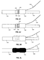
- the wire 230 may be folded over and embedded into the sealant 250, as shown in FIG. 2H.
- one or more additional layers of a thermoplastic adhesive may be applied or wrapped over the wire 230.
- a thermoplastic adhesive may be used to embed the wire.
- the exemplary embodiment shows the wire 230 folded over and oriented generally along the axial direction of the cable, other orientations of the wire may be possible.
- the wire 230 may be angled relative to the axial direction of the cable or helically wrapped around at least a portion of the cable (e.g., around the sealant 250).
- the wire 230 may also be folded before any sealant 250 is applied.
- a second conductor portion 232b lies against a first clamp portion of the clamp 240.
- a second clamp portion of the clamp 240 may then secure the second conductor portion 232b against the first clamp portion of the clamp 240, FIG. 2I.
- a metallic tape 242 e.g., copper tape
- the clamp 240 is a spring clamp
- a single spring clamp may be wrapped or coiled around both the first and second conductor portions 232a, 232b and the clamp portions are coils of the spring clamp.
- the clamp 240 may include separate clamp portions or members that secure the first and second conductor portions 232a, 232b, respectively.
- sealant 252 may also be applied to the shield layer 206 between the clamp 240 and the outer sheath 208, as shown in FIG. 2J.
- the sealant 252 may also be a thermoplastic sealant, such as layers of a thermoplastic adhesive wrapped around the shield layer 206.
- sealant e.g., layers of thermoplastic adhesive
- sealant 254 may be applied over the entire connection, as shown in FIG. 2K.
- the sealant 254 may include a heat shrink member (e.g., a heat shrink tube) with thermoplastic adhesive on an inner surface of the member.
- the heat shrink member may be positioned over the connection, and heat may be applied to shrink the member over the connection, as shown in FIG. 2L.
- the heat may be applied using an electric hot air gun, gas or other fueled heater known to those skilled in the art.
- the sealant 254 may cover about 24 mm of the outer sheath 208.
- the resulting optical cable system connection establishes an electrical connection to a shield layer of the cable and seals the connection and shield layer against leak paths.
- the connection may be made with a relatively short assembly time, without application of excessive heat, without the use of materials hazardous to a marine environment, and for relatively low cost.
- the optical cable shield layer connection may be established on both submarine optical cables and on land optical cables (e.g., adjacent to the submarine optical cables). The connection may be used during installation and repair of cable systems as well as during factory assembly of cable systems.
- a method includes: providing an optical cable with an exposed shield layer extending from an outer sheath and a wire including at least one conductor; securing a first conductor portion of the at least one conductor of the wire to the exposed shield layer; folding the wire; securing a second conductor portion of the at least one conductor of the wire; and sealing at least a portion of the shield layer and the at least one conductor of the wire in a sealant.
- an optical cable shield layer connection system includes an optical cable including a cable core portion, an outer sheath, and a shield layer located between the outer sheath and the cable core portion.
- the shield layer may include an exposed portion extending from the outer sheath.
- the connection system also includes a wire including at least one conductor with at least a first conductor portion secured in contact with the exposed portion of the shield layer and a second conductor portion folded relative to the first conductor portion.
- the connection system also includes at least one clamp securing the first and second conductor portions to the shield layer and a sealant encapsulating the conductor and the exposed portion of the shield layer.
Landscapes
- Physics & Mathematics (AREA)
- General Physics & Mathematics (AREA)
- Optics & Photonics (AREA)
- Engineering & Computer Science (AREA)
- Manufacturing & Machinery (AREA)
- Cable Accessories (AREA)
- Insulated Conductors (AREA)
- Light Guides In General And Applications Therefor (AREA)
Applications Claiming Priority (1)
| Application Number | Priority Date | Filing Date | Title |
|---|---|---|---|
| US11/383,871 US7373054B2 (en) | 2006-05-17 | 2006-05-17 | Optical cable shield layer connection |
Publications (2)
| Publication Number | Publication Date |
|---|---|
| EP1857848A1 true EP1857848A1 (fr) | 2007-11-21 |
| EP1857848B1 EP1857848B1 (fr) | 2012-08-01 |
Family
ID=38357016
Family Applications (1)
| Application Number | Title | Priority Date | Filing Date |
|---|---|---|---|
| EP07108023A Active EP1857848B1 (fr) | 2006-05-17 | 2007-05-11 | Connexion de la couche de protection du câble optique |
Country Status (5)
| Country | Link |
|---|---|
| US (1) | US7373054B2 (fr) |
| EP (1) | EP1857848B1 (fr) |
| JP (1) | JP5158754B2 (fr) |
| AU (1) | AU2007201817B9 (fr) |
| CA (1) | CA2585589C (fr) |
Families Citing this family (43)
| Publication number | Priority date | Publication date | Assignee | Title |
|---|---|---|---|---|
| US8903843B2 (en) | 2006-06-21 | 2014-12-02 | Napo Enterprises, Llc | Historical media recommendation service |
| US9003056B2 (en) | 2006-07-11 | 2015-04-07 | Napo Enterprises, Llc | Maintaining a minimum level of real time media recommendations in the absence of online friends |
| US8059646B2 (en) | 2006-07-11 | 2011-11-15 | Napo Enterprises, Llc | System and method for identifying music content in a P2P real time recommendation network |
| US8805831B2 (en) * | 2006-07-11 | 2014-08-12 | Napo Enterprises, Llc | Scoring and replaying media items |
| US7970922B2 (en) | 2006-07-11 | 2011-06-28 | Napo Enterprises, Llc | P2P real time media recommendations |
| US7680959B2 (en) | 2006-07-11 | 2010-03-16 | Napo Enterprises, Llc | P2P network for providing real time media recommendations |
| US8327266B2 (en) * | 2006-07-11 | 2012-12-04 | Napo Enterprises, Llc | Graphical user interface system for allowing management of a media item playlist based on a preference scoring system |
| US8620699B2 (en) | 2006-08-08 | 2013-12-31 | Napo Enterprises, Llc | Heavy influencer media recommendations |
| US8090606B2 (en) | 2006-08-08 | 2012-01-03 | Napo Enterprises, Llc | Embedded media recommendations |
| US8874655B2 (en) | 2006-12-13 | 2014-10-28 | Napo Enterprises, Llc | Matching participants in a P2P recommendation network loosely coupled to a subscription service |
| US9224427B2 (en) | 2007-04-02 | 2015-12-29 | Napo Enterprises LLC | Rating media item recommendations using recommendation paths and/or media item usage |
| US8112720B2 (en) | 2007-04-05 | 2012-02-07 | Napo Enterprises, Llc | System and method for automatically and graphically associating programmatically-generated media item recommendations related to a user's socially recommended media items |
| US8839141B2 (en) | 2007-06-01 | 2014-09-16 | Napo Enterprises, Llc | Method and system for visually indicating a replay status of media items on a media device |
| US20090049045A1 (en) | 2007-06-01 | 2009-02-19 | Concert Technology Corporation | Method and system for sorting media items in a playlist on a media device |
| US8285776B2 (en) | 2007-06-01 | 2012-10-09 | Napo Enterprises, Llc | System and method for processing a received media item recommendation message comprising recommender presence information |
| US9037632B2 (en) | 2007-06-01 | 2015-05-19 | Napo Enterprises, Llc | System and method of generating a media item recommendation message with recommender presence information |
| US9164993B2 (en) | 2007-06-01 | 2015-10-20 | Napo Enterprises, Llc | System and method for propagating a media item recommendation message comprising recommender presence information |
| US7865522B2 (en) | 2007-11-07 | 2011-01-04 | Napo Enterprises, Llc | System and method for hyping media recommendations in a media recommendation system |
| US9060034B2 (en) | 2007-11-09 | 2015-06-16 | Napo Enterprises, Llc | System and method of filtering recommenders in a media item recommendation system |
| US9224150B2 (en) | 2007-12-18 | 2015-12-29 | Napo Enterprises, Llc | Identifying highly valued recommendations of users in a media recommendation network |
| US9734507B2 (en) | 2007-12-20 | 2017-08-15 | Napo Enterprise, Llc | Method and system for simulating recommendations in a social network for an offline user |
| US8396951B2 (en) | 2007-12-20 | 2013-03-12 | Napo Enterprises, Llc | Method and system for populating a content repository for an internet radio service based on a recommendation network |
| US8060525B2 (en) | 2007-12-21 | 2011-11-15 | Napo Enterprises, Llc | Method and system for generating media recommendations in a distributed environment based on tagging play history information with location information |
| US8117193B2 (en) | 2007-12-21 | 2012-02-14 | Lemi Technology, Llc | Tunersphere |
| US8316015B2 (en) | 2007-12-21 | 2012-11-20 | Lemi Technology, Llc | Tunersphere |
| US8725740B2 (en) | 2008-03-24 | 2014-05-13 | Napo Enterprises, Llc | Active playlist having dynamic media item groups |
| US8484311B2 (en) | 2008-04-17 | 2013-07-09 | Eloy Technology, Llc | Pruning an aggregate media collection |
| US8880599B2 (en) | 2008-10-15 | 2014-11-04 | Eloy Technology, Llc | Collection digest for a media sharing system |
| US8484227B2 (en) | 2008-10-15 | 2013-07-09 | Eloy Technology, Llc | Caching and synching process for a media sharing system |
| US8200602B2 (en) | 2009-02-02 | 2012-06-12 | Napo Enterprises, Llc | System and method for creating thematic listening experiences in a networked peer media recommendation environment |
| EP2510582B1 (fr) * | 2009-12-10 | 2018-02-21 | Prysmian S.p.A. | Connecteur de polarisation |
| US8328431B2 (en) * | 2010-02-01 | 2012-12-11 | Tyco Electronics Subsea Communications Llc | Coupling multiple conductor undersea optical cables to an undersea device with an isolated bypass conductive path across the undersea device |
| US9015109B2 (en) | 2011-11-01 | 2015-04-21 | Lemi Technology, Llc | Systems, methods, and computer readable media for maintaining recommendations in a media recommendation system |
| CN203931563U (zh) * | 2013-01-22 | 2014-11-05 | 住友电气工业株式会社 | 多芯线缆 |
| EP3034561B1 (fr) * | 2014-12-19 | 2019-02-06 | NKT HV Cables GmbH | Procédé de fabrication d'un joint de câble CC à haute tension et joint de câble CC à haute tension |
| US9557509B2 (en) | 2015-02-27 | 2017-01-31 | Electric Motion Company, Inc. | Fiber optic cable external shield connector |
| BR112017025185B1 (pt) * | 2015-06-02 | 2022-07-05 | Nkt Hv Cables Gmbh | Montagem de juntas rígidas |
| EP3104463B1 (fr) * | 2015-06-12 | 2020-11-11 | Siemens Aktiengesellschaft | Connecteur sous-marin |
| US10566757B2 (en) | 2016-12-09 | 2020-02-18 | Lear Corporation | Method of heat shrinking a protective sleeve onto an electrical connection |
| JP7017591B2 (ja) * | 2020-02-04 | 2022-02-08 | 矢崎総業株式会社 | 端子付電線及びセンサ固定方法 |
| CN112002469B (zh) * | 2020-08-18 | 2022-02-11 | 昆山联滔电子有限公司 | 一种电缆及电缆的加工方法 |
| CN112327423B (zh) * | 2020-10-28 | 2025-06-24 | 中航光电科技股份有限公司 | 一种光纤插头连接器和连接器组件 |
| GB2631982A (en) * | 2023-07-20 | 2025-01-22 | Global Marine Systems Ltd | Sensor pod |
Citations (6)
| Publication number | Priority date | Publication date | Assignee | Title |
|---|---|---|---|---|
| US4032205A (en) * | 1976-09-10 | 1977-06-28 | Rte Corporation | Adaptor for a high voltage cable |
| US4950343A (en) | 1988-09-08 | 1990-08-21 | Raychem Corporation | Method of cable sealing |
| EP0430533A2 (fr) * | 1989-11-29 | 1991-06-05 | AT&T Corp. | Portion impérmeable de câble et moyen de le fabriquer |
| WO1993011584A1 (fr) * | 1991-12-05 | 1993-06-10 | Raychem S.A. | Connecteur electrique |
| US5528718A (en) * | 1993-04-16 | 1996-06-18 | Raychem Corporation | Fiber optic cable system including main and drop cables and associated fabrication method |
| US5646370A (en) * | 1995-04-28 | 1997-07-08 | Minnesota Mining And Manufacturing Company | Permanent attachment of grounding wire |
Family Cites Families (12)
| Publication number | Priority date | Publication date | Assignee | Title |
|---|---|---|---|---|
| JPS6179303U (fr) * | 1984-10-29 | 1986-05-27 | ||
| JPH0424751Y2 (fr) * | 1985-06-25 | 1992-06-11 | ||
| JPH0746029Y2 (ja) * | 1989-06-26 | 1995-10-18 | 沖電気工業株式会社 | ケーブル端末の水密構造 |
| JPH0590824U (ja) * | 1992-05-22 | 1993-12-10 | 株式会社白山製作所 | 接続端子函の集合アース板 |
| JPH10170775A (ja) * | 1996-12-09 | 1998-06-26 | Furukawa Electric Co Ltd:The | 光海底ケーブル用光ファイバユニット |
| JPH11234885A (ja) * | 1998-02-12 | 1999-08-27 | Hitachi Cable Ltd | 直線接続部 |
| US6853780B1 (en) * | 1999-03-31 | 2005-02-08 | Pirelli Cavi E Sistemi S.P.A. | Optical cable for telecommunications |
| JP2002043010A (ja) * | 2000-07-21 | 2002-02-08 | Ubukata Industries Co Ltd | 防水構造を有するリード線接続部の製造方法 |
| JP4298450B2 (ja) * | 2003-09-24 | 2009-07-22 | 住友電気工業株式会社 | 超電導ケーブルの端末構造 |
| US7006739B2 (en) * | 2003-12-15 | 2006-02-28 | Corning Cable Systems Llc | Pre-connectorized fiber optic distribution cable |
| US7450804B2 (en) * | 2004-05-24 | 2008-11-11 | Corning Cable Systems Llc | Distribution cable assembly having overmolded mid-span access location |
| US7418177B2 (en) * | 2005-11-10 | 2008-08-26 | Adc Telecommunications, Inc. | Fiber optic cable breakout system, packaging arrangement, and method of installation |
-
2006
- 2006-05-17 US US11/383,871 patent/US7373054B2/en active Active
-
2007
- 2007-04-20 CA CA2585589A patent/CA2585589C/fr not_active Expired - Fee Related
- 2007-04-24 AU AU2007201817A patent/AU2007201817B9/en not_active Ceased
- 2007-05-11 EP EP07108023A patent/EP1857848B1/fr active Active
- 2007-05-17 JP JP2007131526A patent/JP5158754B2/ja active Active
Patent Citations (6)
| Publication number | Priority date | Publication date | Assignee | Title |
|---|---|---|---|---|
| US4032205A (en) * | 1976-09-10 | 1977-06-28 | Rte Corporation | Adaptor for a high voltage cable |
| US4950343A (en) | 1988-09-08 | 1990-08-21 | Raychem Corporation | Method of cable sealing |
| EP0430533A2 (fr) * | 1989-11-29 | 1991-06-05 | AT&T Corp. | Portion impérmeable de câble et moyen de le fabriquer |
| WO1993011584A1 (fr) * | 1991-12-05 | 1993-06-10 | Raychem S.A. | Connecteur electrique |
| US5528718A (en) * | 1993-04-16 | 1996-06-18 | Raychem Corporation | Fiber optic cable system including main and drop cables and associated fabrication method |
| US5646370A (en) * | 1995-04-28 | 1997-07-08 | Minnesota Mining And Manufacturing Company | Permanent attachment of grounding wire |
Also Published As
| Publication number | Publication date |
|---|---|
| US20070269169A1 (en) | 2007-11-22 |
| AU2007201817B9 (en) | 2013-07-11 |
| JP5158754B2 (ja) | 2013-03-06 |
| CA2585589C (fr) | 2015-01-20 |
| AU2007201817A1 (en) | 2007-12-06 |
| EP1857848B1 (fr) | 2012-08-01 |
| AU2007201817B2 (en) | 2012-09-20 |
| JP2007312594A (ja) | 2007-11-29 |
| CA2585589A1 (fr) | 2007-11-17 |
| US7373054B2 (en) | 2008-05-13 |
Similar Documents
| Publication | Publication Date | Title |
|---|---|---|
| CA2585589C (fr) | Connexion de couche blindee de cable a fibres optiques | |
| US10257967B2 (en) | Electromagnetic interference splice shield | |
| CA2386210C (fr) | Connexions et terminaisons pour cables | |
| CN105098559A (zh) | 分接屏蔽线缆的方法和通过该方法制成的线缆 | |
| US9979167B1 (en) | Device and method for splicing shielded wire cables | |
| EP3619782B1 (fr) | Câble à fil blindé épissé et son procédé de fabrication | |
| JP7685607B2 (ja) | シールド接続アセンブリ、ケーブルアセンブリ及びケーブルアセンブリの製造方法 | |
| CN101990728B (zh) | 一种将电缆中单个电线的电磁屏蔽延伸到电连接器的方法 | |
| US5854444A (en) | Environmentally sealed splice kit for shielded cable and method therefor | |
| JP2011065964A (ja) | 止水部を備えたシールド電線および該シールド電線の止水部の形成方法 | |
| JP4767137B2 (ja) | シールド線の止水方法および止水構造 | |
| JP2015186296A (ja) | 絶縁被覆電線の止水構造およびワイヤハーネス | |
| JP4928178B2 (ja) | シールド線のドレン線止水方法およびドレン線止水構造 | |
| CN112490769B (zh) | 一种多股芯线三段式电连接器及其连接方法 | |
| CN117200126A (zh) | 接头组件、接头系统和安装这种接头组件的方法 | |
| JPS6217764Y2 (fr) | ||
| WO2025045930A1 (fr) | Procédé de fourniture d'un raccord pour câbles haute tension | |
| KR100250980B1 (ko) | 통신케이블금속층본딩클램프 | |
| JP5264130B2 (ja) | 線間止水方法 | |
| RU2207687C1 (ru) | Муфта медножильного кабеля в алюминиевой оболочке и способ соединения медножильных кабелей (варианты) | |
| JP2022134412A (ja) | ワイヤハーネス、およびワイヤハーネスの製造方法 |
Legal Events
| Date | Code | Title | Description |
|---|---|---|---|
| PUAI | Public reference made under article 153(3) epc to a published international application that has entered the european phase |
Free format text: ORIGINAL CODE: 0009012 |
|
| AK | Designated contracting states |
Kind code of ref document: A1 Designated state(s): AT BE BG CH CY CZ DE DK EE ES FI FR GB GR HU IE IS IT LI LT LU LV MC MT NL PL PT RO SE SI SK TR |
|
| AX | Request for extension of the european patent |
Extension state: AL BA HR MK YU |
|
| 17P | Request for examination filed |
Effective date: 20080327 |
|
| 17Q | First examination report despatched |
Effective date: 20080509 |
|
| AKX | Designation fees paid |
Designated state(s): DE FR GB IT |
|
| RAP1 | Party data changed (applicant data changed or rights of an application transferred) |
Owner name: TYCO TELECOMMUNICATIONS (US) INC. |
|
| RAP1 | Party data changed (applicant data changed or rights of an application transferred) |
Owner name: TYCO ELECTRONICS SUBSEA COMMUNICATIONS LLC |
|
| RAP1 | Party data changed (applicant data changed or rights of an application transferred) |
Owner name: TYCO ELECTRONICS SUBSEA COMMUNICATIONS LLC |
|
| GRAP | Despatch of communication of intention to grant a patent |
Free format text: ORIGINAL CODE: EPIDOSNIGR1 |
|
| GRAS | Grant fee paid |
Free format text: ORIGINAL CODE: EPIDOSNIGR3 |
|
| GRAA | (expected) grant |
Free format text: ORIGINAL CODE: 0009210 |
|
| AK | Designated contracting states |
Kind code of ref document: B1 Designated state(s): DE FR GB IT |
|
| REG | Reference to a national code |
Ref country code: GB Ref legal event code: FG4D |
|
| REG | Reference to a national code |
Ref country code: DE Ref legal event code: R096 Ref document number: 602007024276 Country of ref document: DE Effective date: 20121011 |
|
| PLBE | No opposition filed within time limit |
Free format text: ORIGINAL CODE: 0009261 |
|
| STAA | Information on the status of an ep patent application or granted ep patent |
Free format text: STATUS: NO OPPOSITION FILED WITHIN TIME LIMIT |
|
| 26N | No opposition filed |
Effective date: 20130503 |
|
| REG | Reference to a national code |
Ref country code: DE Ref legal event code: R097 Ref document number: 602007024276 Country of ref document: DE Effective date: 20130503 |
|
| REG | Reference to a national code |
Ref country code: FR Ref legal event code: PLFP Year of fee payment: 10 |
|
| REG | Reference to a national code |
Ref country code: FR Ref legal event code: PLFP Year of fee payment: 11 |
|
| REG | Reference to a national code |
Ref country code: FR Ref legal event code: PLFP Year of fee payment: 12 |
|
| REG | Reference to a national code |
Ref country code: DE Ref legal event code: R082 Ref document number: 602007024276 Country of ref document: DE Representative=s name: MARKS & CLERK (LUXEMBOURG) LLP, LU Ref country code: DE Ref legal event code: R081 Ref document number: 602007024276 Country of ref document: DE Owner name: TYCO ELECTRONICS SUBSEA COMMUNICATIONS LLC (N., US Free format text: FORMER OWNER: TYCO ELECTRONICS SUBSEA COMMUNICATIONS LLC, MORRISTOWN, N.J., US Ref country code: DE Ref legal event code: R081 Ref document number: 602007024276 Country of ref document: DE Owner name: SUBCOM, LLC (N.D.GES.D. STAATES DELAWARE), EAT, US Free format text: FORMER OWNER: TYCO ELECTRONICS SUBSEA COMMUNICATIONS LLC, MORRISTOWN, N.J., US |
|
| REG | Reference to a national code |
Ref country code: DE Ref legal event code: R082 Ref document number: 602007024276 Country of ref document: DE Representative=s name: MARKS & CLERK (LUXEMBOURG) LLP, LU Ref country code: DE Ref legal event code: R081 Ref document number: 602007024276 Country of ref document: DE Owner name: SUBCOM, LLC (N.D.GES.D. STAATES DELAWARE), EAT, US Free format text: FORMER OWNER: TYCO ELECTRONICS SUBSEA COMMUNICATIONS LLC (N.D.GES.D. STAATES DELAWARE), WILMINGTON, DE, US |
|
| P01 | Opt-out of the competence of the unified patent court (upc) registered |
Effective date: 20230607 |
|
| PGFP | Annual fee paid to national office [announced via postgrant information from national office to epo] |
Ref country code: DE Payment date: 20240319 Year of fee payment: 18 |
|
| PGFP | Annual fee paid to national office [announced via postgrant information from national office to epo] |
Ref country code: IT Payment date: 20240411 Year of fee payment: 18 |
|
| REG | Reference to a national code |
Ref country code: DE Ref legal event code: R119 Ref document number: 602007024276 Country of ref document: DE |
|
| PGFP | Annual fee paid to national office [announced via postgrant information from national office to epo] |
Ref country code: GB Payment date: 20260312 Year of fee payment: 20 |
|
| PG25 | Lapsed in a contracting state [announced via postgrant information from national office to epo] |
Ref country code: DE Free format text: LAPSE BECAUSE OF NON-PAYMENT OF DUE FEES Effective date: 20251202 |
|
| PG25 | Lapsed in a contracting state [announced via postgrant information from national office to epo] |
Ref country code: IT Free format text: LAPSE BECAUSE OF NON-PAYMENT OF DUE FEES Effective date: 20250511 |
|
| PGFP | Annual fee paid to national office [announced via postgrant information from national office to epo] |
Ref country code: FR Payment date: 20260309 Year of fee payment: 20 |