EP1863294A2 - Rekursives Filtersystem für ein Videosignal - Google Patents
Rekursives Filtersystem für ein Videosignal Download PDFInfo
- Publication number
- EP1863294A2 EP1863294A2 EP07252226A EP07252226A EP1863294A2 EP 1863294 A2 EP1863294 A2 EP 1863294A2 EP 07252226 A EP07252226 A EP 07252226A EP 07252226 A EP07252226 A EP 07252226A EP 1863294 A2 EP1863294 A2 EP 1863294A2
- Authority
- EP
- European Patent Office
- Prior art keywords
- picture element
- image
- luminance
- chrominance
- stored
- Prior art date
- Legal status (The legal status is an assumption and is not a legal conclusion. Google has not performed a legal analysis and makes no representation as to the accuracy of the status listed.)
- Withdrawn
Links
Images


Classifications
-
- G—PHYSICS
- G06—COMPUTING OR CALCULATING; COUNTING
- G06T—IMAGE DATA PROCESSING OR GENERATION, IN GENERAL
- G06T5/00—Image enhancement or restoration
- G06T5/70—Denoising; Smoothing
-
- G—PHYSICS
- G06—COMPUTING OR CALCULATING; COUNTING
- G06T—IMAGE DATA PROCESSING OR GENERATION, IN GENERAL
- G06T5/00—Image enhancement or restoration
- G06T5/20—Image enhancement or restoration using local operators
-
- H—ELECTRICITY
- H04—ELECTRIC COMMUNICATION TECHNIQUE
- H04N—PICTORIAL COMMUNICATION, e.g. TELEVISION
- H04N19/00—Methods or arrangements for coding, decoding, compressing or decompressing digital video signals
- H04N19/10—Methods or arrangements for coding, decoding, compressing or decompressing digital video signals using adaptive coding
- H04N19/102—Methods or arrangements for coding, decoding, compressing or decompressing digital video signals using adaptive coding characterised by the element, parameter or selection affected or controlled by the adaptive coding
- H04N19/117—Filters, e.g. for pre-processing or post-processing
-
- H—ELECTRICITY
- H04—ELECTRIC COMMUNICATION TECHNIQUE
- H04N—PICTORIAL COMMUNICATION, e.g. TELEVISION
- H04N19/00—Methods or arrangements for coding, decoding, compressing or decompressing digital video signals
- H04N19/10—Methods or arrangements for coding, decoding, compressing or decompressing digital video signals using adaptive coding
- H04N19/134—Methods or arrangements for coding, decoding, compressing or decompressing digital video signals using adaptive coding characterised by the element, parameter or criterion affecting or controlling the adaptive coding
- H04N19/136—Incoming video signal characteristics or properties
- H04N19/14—Coding unit complexity, e.g. amount of activity or edge presence estimation
-
- H—ELECTRICITY
- H04—ELECTRIC COMMUNICATION TECHNIQUE
- H04N—PICTORIAL COMMUNICATION, e.g. TELEVISION
- H04N19/00—Methods or arrangements for coding, decoding, compressing or decompressing digital video signals
- H04N19/10—Methods or arrangements for coding, decoding, compressing or decompressing digital video signals using adaptive coding
- H04N19/169—Methods or arrangements for coding, decoding, compressing or decompressing digital video signals using adaptive coding characterised by the coding unit, i.e. the structural portion or semantic portion of the video signal being the object or the subject of the adaptive coding
- H04N19/182—Methods or arrangements for coding, decoding, compressing or decompressing digital video signals using adaptive coding characterised by the coding unit, i.e. the structural portion or semantic portion of the video signal being the object or the subject of the adaptive coding the unit being a pixel
-
- H—ELECTRICITY
- H04—ELECTRIC COMMUNICATION TECHNIQUE
- H04N—PICTORIAL COMMUNICATION, e.g. TELEVISION
- H04N19/00—Methods or arrangements for coding, decoding, compressing or decompressing digital video signals
- H04N19/80—Details of filtering operations specially adapted for video compression, e.g. for pixel interpolation
-
- H—ELECTRICITY
- H04—ELECTRIC COMMUNICATION TECHNIQUE
- H04N—PICTORIAL COMMUNICATION, e.g. TELEVISION
- H04N19/00—Methods or arrangements for coding, decoding, compressing or decompressing digital video signals
- H04N19/85—Methods or arrangements for coding, decoding, compressing or decompressing digital video signals using pre-processing or post-processing specially adapted for video compression
-
- H—ELECTRICITY
- H04—ELECTRIC COMMUNICATION TECHNIQUE
- H04N—PICTORIAL COMMUNICATION, e.g. TELEVISION
- H04N5/00—Details of television systems
- H04N5/14—Picture signal circuitry for video frequency region
- H04N5/21—Circuitry for suppressing or minimising disturbance, e.g. moiré or halo
-
- G—PHYSICS
- G06—COMPUTING OR CALCULATING; COUNTING
- G06T—IMAGE DATA PROCESSING OR GENERATION, IN GENERAL
- G06T2207/00—Indexing scheme for image analysis or image enhancement
- G06T2207/10—Image acquisition modality
- G06T2207/10016—Video; Image sequence
Definitions
- This invention relates to a recursive filter system for a video signal and in particular to localised diffusion to enhance noise attenuation in recursive filtering.
- the index i of each of R ( i ), C ( i ) and S ( i ) is the same so that the pels are spatially co-located in each respective image.
- the index of pels in each image, i may be defined in more than one-dimension; conventionally it is convenient to use two, corresponding to the commonly-used raster scanning of television images.
- R f ( i ) becomes R f ( x,y ).
- the index f corresponds to the frame or temporal dimension.
- K is the fractional parameter that controls a proportion of the current image C ( x,y ) to previous image S ( x,y ) used to make the current result R ( x,y ).
- the parameter K does not change frequently with time, typically once per complete image, and in extreme cases may be fixed indefinitely at one value. It may also be operated under direct manual control. Experience shows that this is not satisfactory for some image material.
- K The value of K is used to control the degree of filtering (and hence noise attenuation) and that attenuation increases as K tends toward 0.
- This is an ideal setting to process still images where the absence of motion allows optimal filtering for noise reduction.
- This technique has some limitations. Objects in motion captured in successive images cause their respective pels to change position in the image and thus their index ( x,y ). Motion leads to changes in the position, i.e. lateral movement, or attitude, i.e. rotational movement, of recognisable objects in the image even when there is no camera movement. Changes in object position are also caused by camera movement such as panning or tilting, or both, and changes in object position and scale caused by zooming, i.e. changes in focal length of the camera lens.
- the filter described above will therefore add together pels in successive images whose indices ( x,y ) no longer correspond to a same part of such moving objects and consequently motion will be confused with noise and the filter will reduce the value of the differences between successive images caused by motion as if it were noise.
- viewed images tend to blur for small amounts of movement and larger motion tends to create ghosts of any moving objects substantially compromising the image with artefacts.
- the essence of the problem is an inability to discriminate reliably between noise and motion, recognising that small amounts of motion can be difficult to distinguish from noise.
- K can be defined on a per pel basis - i.e. K ( x,y ) - from information derived from the pel C ( x,y ) being processed and the surrounding pels.
- the value of K ( x,y ) can be derived from the temporal difference between co-located pels, however, this produces artefacts because this local difference is a function both of the sought after motion and the noise in the image.
- To discriminate between noise and motion requires the measurement and the subsequent exploitation of the differing statistical properties of the motion and the noise.
- K may be varied pel-by-pel appropriately to reduce noise but also to suppress unwanted artefacts, so that K becomes K ( x,y ).
- a recursive filter system for a video image comprising: storage means arranged to store a first image of stored picture elements S ( x,y ); weighting means arranged to generate weighted values W ( x,y ) of luminance and chrominance of a stored picture element S ( x,y ) by summing weighted values B ( x,y ).
- first proportional parameter A ( x,y ) for the stored picture element based on a modular sum of differences between luminance and chrominance of the stored picture element and of surrounding picture elements; first combinatorial means arranged to use the first proportional parameter A ( x,y ) to generate a weighted picture element M(x,y ) from a proportion A ( x,y ) of the stored picture element S ( x,y ) and a complementary proportion 1- A ( x,y ) of the weighted value W ( x , y ); inputting means arranged to input picture elements of a next image and a second proportional parameter K; second combinatorial means arranged to use the second proportional parameter K to generate a filtered image R ( x,y ) by combining a proportion K of each input picture element C ( x,y ) of the next image with a complementary proportion
- the weighting means is arranged to weight neighbouring picture elements using an array of weighting values.
- the generating means comprises means for calculating a sum of absolute differences between chrominance and luminance of the picture element and surrounding picture elements.
- the generating means comprises means for calculating a sum of squares of the differences between chrominance and luminance of the picture element and surrounding picture elements.
- the generating means comprises means for calculating a positive square root of the sum of squares of the differences between chrominance and luminance of the picture element and surrounding picture elements.
- the generating means comprises multiplication means for multiplying the modular sum of differences between luminance and chrominance of the stored picture element and of surrounding picture elements by the luminance and chrominance of the stored picture element respectively.
- the generating means comprises scalar means for generating a normalised value of the proportional parameter A ( x,y ).
- the recursive filter system further comprises programmable spatial low pass filter means and means for estimating spatial noise in the input image for controlling the low pass filter means, such that the input image is filtered proportionally to noise detected.
- output from the means for estimating spatial noise is adjustable dependent upon a degree of detail detected in a region of an image being processed.
- the recursive filter system further comprises a logic block controllable by a factor K indicative of a degree of motion in an area of an image being processed such that a proportional factor applied to the combinatorial means is a function of the noise and a degree of motion in a vicinity of a picture element being processed.
- a method of enhancing noise attenuation in recursive filtering of a video image comprising the steps of: storing a first image to comprise stored picture elements S ( x,y ); generating a weighted value W ( x,y ) of luminance and chrominance of a stored picture element by summing weighted values B ( x,y ) .S ( x,y ) of luminance and chrominance of the picture element and neighbouring picture elements; generating a first proportional parameter A ( x,y ) for the stored picture element based on a sum of differences between the luminance and chrominance of the stored picture element and surrounding picture elements; using the first proportional parameter A ( x,y ) to generate a weighted picture element M ( x,y ) from a proportion A ( x,y ) of the stored picture element S ( x,y ) and a complementary proportion 1 -A ( x,y )
- generating a weighted value comprises using an array of weighting values to weight neighbouring picture elements.
- generating a weighted value comprises calculating a sum of absolute differences between chrominance and luminance of the picture element and surrounding picture elements.
- generating a weighted value comprises calculating a sum of squares of the differences between chrominance and luminance of the picture element and surrounding picture elements.
- generating a weighted value comprises calculating a positive square root of the sum of squares of the differences between chrominance and luminance of the picture element and surrounding picture elements
- generating a weighted value comprises multiplying the modular sum of differences between luminance and chrominance of the stored picture element and of surrounding picture elements by the luminance and chrominance of the stored picture element, respectively.
- generating a weighted value comprises generating a normalised value of the proportional parameter A(x,y).
- the method further comprises filtering the input image with programmable spatial low pass filter means using means for estimating spatial noise in the input image for controlling the low pass filter means, such that the input image is filtered proportionally to noise detected.
- output from the means for estimating spatial noise is adjustable dependent upon a degree of detail detected in a region of an image being processed.
- the method further comprises using a logic block controllable by a factor K indicative of a degree of motion in an area of an image being processed such that a proportional factor applied to the combinatorial means is a functional of the noise and a degree of motion in a vicinity of a picture element being processed.
- a computer program comprising code means for performing all the steps of the method described above when the program is run on one or more computers.
- Equation 1 a weighted average W f ( x,y ) of the surrounding pels is formed and a value for M f ( x,y ) generated linearly from these two values based on the localised activity between the current image and stored results.
- This linear relation is controlled through a parameter A where A is derived from local activity of the image; the parameter A can also be used as a means of accounting for psychovisual factors such as masking which can assist in making the noise filtering process optimally effective.
- One means of applying such a psychovisual mask in this case the use of local contrast measures, is described in EP 0986264 and US 6,701,019 .
- Equation 4a The value of the parameter A ( x,y ), which is calculated independently for each pel, is illustrated in Equations 4a - 4c and is calculated as follows, where the first line in each of Equations 4a and 4b forms a mean over the array of pels around the pel of current interest, S f ( x,y ), in the stored picture.
- Equation 4c the value of A Total ( x,y ) is calculated by adding A luma to A chroma ; other means of combination may be used such as averaging or largest value or sum of squares, as appropriate.
- a chroma is a composite of the red and blue difference values and should be calculated from the spatially corresponding information in the video stream.
- Equations 4a - 4c the values of A luma ( x,y ), A chroma ( x,y ) and A Total ( x,y ), which are always positive, are calculated in this example from the absolute value of the differences between the mean level near the index point ( x,y ) and the pel values around that point, S f ( x,y ).
- Equation 7 The calculation of the weighted value of S f ( x,y ) is performed according to Equation 7 and Table 1, where only the luminance calculation is given, it being understood that the chrominance A C ( x,y ) value of will be calculated using a similar expression and table and the value of A Total ( x,y ) will be calculated according to a similar expression to that in Equation 4c or equivalent:
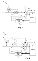
- Figure 1 shows an overview of an implementation of a recursive filter system 10 according to the invention, in which separate luminance and chrominance processing paths are assumed to be combined.
- a first multiplier 121 has a first input 11 for a source image C and a second input 16 for the fractional parameter K.
- An output of the first multiplier 121 is connected to a first input of an adder 123.
- the fractional parameter K is also input to a block 161 to calculate the complementary proportion 1- K and the output of the block 161 is connected to a first input of a second multiplier 122 in parallel with the first multiplier 121.
- An output of the second multiplier 122 is connected to a second input of the adder 123.
- An output of the adder 123 is connected to an output port 15 of the recursive filter system and to a write port of a memory 14.
- a read port of the memory 14 is connected to an input 131 of a programmable spatial filter 13, also having an input for luminance and chrominance parameters.
- An output 135 of the programmable spatial filter, 13, is connected to a second input of the second multiplier 122.
- a current image C enters the system at the first input 11 of the first multiplier 121.
- the arrangement 12 of the first and second multipliers 121, 122 and the adder 123 performs the operation of Equation 2, and fades R between the current image C and a processed pel field S are written to memory 14 controlled by a value of parameter K entered at the second input 16 of the first multiplier 121.
- a processed image is output from the recursive filter system 10 at output 15.
- the programmable spatial filter 13 represents an enhancement provided by the invention to a conventional recursive filter system and inputs an array of pels local to a pel being processed, derives an activity and weighted average and processes them by the luminance Z and chrominance Y, where separate luminance and chrominance processing paths are shown combined.
- the input 131 of the programmable spatial filter 13 is connected in parallel to a first input of a third multiplier 1341 forming an element of a multiplier and adder arrangement 134, to a block 132 for calculating a weighting function and to an activity estimator block 133.
- First and second outputs from the activity estimator 133 feed first inputs of fifth and sixth multipliers, 1371 and 1372 in parallel.
- Second inputs of the fifth and sixth multipliers, 1371 and 1372 have inputs for Z & Y parameters respectively.
- Outputs of the fifth and sixth multipliers, 1371 and 1372 are connected to first and second inputs of a third adder 1373, respectively.
- An output of adder 1373 is connected to an input of a scalar block, 136.
- An output of the scalar block 136 is connected to a second input of the third multiplier 1341.
- An output of the scalar block 136 is also input to a 1- A block 138 for calculating a complement of A and an output of the 1- A block 138 is connected to a first input of a fourth multiplier 1342 forming an element of the multiplier and adder arrangement 134.
- An output of the weighting block 132 for calculating a weighting function is connected to a second input of the fourth multiplier 1342.
- Outputs of the third and fourth multipliers 1341, 1342 are connected to respective first and second inputs of a second adder 1343 forming an element of the arrangement 134.
- An output of the second adder forms the output 135 of the programmable spatial filter 13.
- an image S is stored, step 51, in the memory 14.
- Picture elements S ( x,y ) are read from the memory 14 and weighted values W(x,y) are generated, step 52, for a retrieved picture element S ( x,y ) by the weighting block 132 using Equation 7 and an array of weighting values B luma ( m,n ) as exemplified by Table 1.
- a first proportional parameter A total ( x,y ) is generated, step 53, for the luminance and chrominance of the picture element based on a sum of differences as exemplified in Equations 4a and 4b, 5 or 6 together with Equation 4c, i.e.
- a scaler value of the first proportional parameter A ( x,y ) is obtained by the scaler 136.
- a weighted picture element M ( x,y ) is generated, step 54, from a proportion of the stored picture element S ( x,y ) and a complementary proportion of the weighted value W ( x,y ) by the fader arrangement 134.
- Picture elements C ( x,y ) of a next image are input, step 55, at input 11 and a second proportional parameter K input at the second input 16.
- a filtered image R ( x,y ) is generated, step 56, from a proportion of the input picture element C ( x,y ) and a complementary proportion of the weighted picture element M ( x,y ) by the fader arrangement 12.
- the filtered picture element R ( x,y ) is output from the output 15 and stored, step 57, in the memory 14 for processing a succeeding image.
- an array of pels local to a pel being processed enter the programmable spatial filter 13 at input 131.
- Weighting block 132 derives a weighting function W ( x,y ), generated as illustrated in Equation 7;
- Activity estimator 133 and scaler 136 derive A total ( x,y ) using Equation 4, the multiplication by luminance and chrominance parameters Z and Y being separated out for clarity and where separate luminance and chrominance processing paths are assumed to be combined.
- Block 136 implements a required scaling operation on A to render its value in a range 0 to 1 and thence to enable the programmable spatial filter to effect a fade between the spatially co-located value S(x,y) and the weighted average W ( x,y ) .
- the fader arrangement 134 derives the interim result M ( x,y ) from Equation 3.
- Table 2 shows a summary of the resultant gains in luminance peak signal to noise ratio, PSNR. Although numerically small, these gains proved to be significant in terms of perceived picture quality.
- Table 2 Resultant systemic gains in PSNR Sequence name PSNR Without Enhancement PSNR With Enhancement Gain Ray Charles Montreux 36.1dB 36.47dB 0.37dB Moscow 38.26dB 38.91dB 0.65dB 101 Dalmatians wedding 39.8dB 40.6dB 0.8dB Women keyed over flowers 35.15dB 36.11dB 0.96dB
- Equation 8 the pel stream represented by C ( x,y ) is modified in a similar way to that used above to produce the modified stored pel stream M ( x,y ).
- D f x ⁇ y V .
- N f x ⁇ y Equation 8 Modified input recursive noise reduction calculation where D f (x,y) is a weighted and filtered form of C f (xy) using similar techniques to those described above.
- V is a control value and N is a spatially filtered version of C.
- a image source input 11 is connected to an input of a programmable spatial low pass filter 31.
- the image source input 11 is also connected to an input of a block 33 for estimating spatial noise in a current image.
- An output of block 33 is connected to a control input 37 of the programmable spatial low pass filter 31.
- An output of the programmable spatial low pass filter 31 is connected to an input of a fader 32, which also has a control input for the fractional parameter K .
- An output of the fader 32 is connected to an output 35 of the recursive filter system 30 and also to a write input of a memory 14.
- a read output of the memory 14 is connected to an input of a programmable spatial filter 13 which also has an input for luminance and chrominance parameters Z & Y.
- An output of the programmable spatial filter 13 is connected to a second input of the fader 32.
- a variable degree of filtering by the programmable spatial low pass filter 31 is varied by a numeric value input at the control input 37.
- Block 33 provides an estimate of the spatial noise within a current image being processed, using, for example, a noise analyser as disclosed in the Applicant's application filed on the same date as this application under Applicant's reference number PI13931GB. This value at input 37 is used to control the low pass spatial filter 31.
- the value at input 37 varies on a pel by pel basis to filter only where noise is detected.
- block 33 can lower its resultant output value if the input image is determined to have a high degree of detail in a region being processed.
- This embodiment combines the spatial filters but does not change the way that the final output value is selected at output 35.
- An optimal result can be achieved by applying spatial filtering disproportionately to objects in motion, since psycho-visual aspects of objects in motion do not allow the eye to pick up blurring so readily.
- Figure 4 illustrates a combined system 40 to derive the output R ( x,y ) at output 45 from a combination of the input C , a filtered version D of the input and a filtered version M of the stored output.
- an image source input 11 is connected to an input of a programmable spatial low pass filter 31.
- the image source input 11 is also connected to an input of a block 33 for estimating spatial noise in a current image.
- An output of block 33 is connected to a control input 37 of the programmable spatial low pass filter 31.
- An output of the programmable spatial low pass filter 31 is connected to an input of a fader 42.
- the output of the block 33 for estimating spatial noise is also input to a block 48 which has a further input of the recursive filter system for the fractional parameter K .
- An output of the block 48 forms a control input to the fader 42.
- the fader 42 has an additional input from the image source input 11.
- An output of the fader 42 is connected to an output 45 of the recursive filter system 40 and also to a write input of a memory 14.
- a read output of the memory 14 is connected to an input of a recursive filter 13 which also has a luminance and chrominance input.
- An output of the recursive filter 13 is connected to a third input of the fader 32.
- Equation 9 is an example of one manner of operation of control block 48.
- K ⁇ i 1 1 - N i 10 + 1 - K i 10 0 ⁇ K ⁇ 1 0 ⁇ N ⁇ 1 Equation 9 : Exemplary motion - spatial noise calculation
- N is the estimated noise and K ' is the derived motion estimation.
- inventions of the invention reduce a noise component in a value taken from a stored pel array and an equivalent input array to enhance noise attenuation and, where large difference information has formed in the store, the embodiments increase a rate of convergence to remove any ghosting from the processed image.
Landscapes
- Engineering & Computer Science (AREA)
- Multimedia (AREA)
- Signal Processing (AREA)
- Physics & Mathematics (AREA)
- General Physics & Mathematics (AREA)
- Theoretical Computer Science (AREA)
- Picture Signal Circuits (AREA)
- Processing Of Color Television Signals (AREA)
Applications Claiming Priority (1)
| Application Number | Priority Date | Filing Date | Title |
|---|---|---|---|
| GB0610968A GB2438660B (en) | 2006-06-02 | 2006-06-02 | Recursive filter system for a video signal |
Publications (2)
| Publication Number | Publication Date |
|---|---|
| EP1863294A2 true EP1863294A2 (de) | 2007-12-05 |
| EP1863294A3 EP1863294A3 (de) | 2009-09-23 |
Family
ID=36694884
Family Applications (1)
| Application Number | Title | Priority Date | Filing Date |
|---|---|---|---|
| EP07252226A Withdrawn EP1863294A3 (de) | 2006-06-02 | 2007-05-31 | Rekursives Filtersystem für ein Videosignal |
Country Status (5)
| Country | Link |
|---|---|
| US (1) | US7903901B2 (de) |
| EP (1) | EP1863294A3 (de) |
| JP (1) | JP2007325253A (de) |
| CA (1) | CA2590063A1 (de) |
| GB (1) | GB2438660B (de) |
Families Citing this family (8)
| Publication number | Priority date | Publication date | Assignee | Title |
|---|---|---|---|---|
| GB2438661A (en) * | 2006-06-02 | 2007-12-05 | Tandberg Television Asa | Recursive filtering of a video image including weighting factors for neighbouring picture elements |
| FR2914465B1 (fr) * | 2007-03-30 | 2010-11-26 | Commissariat Energie Atomique | Procede de correction de bruit spatial d'un capteur d'image matriciel. |
| JP2010041697A (ja) * | 2008-08-08 | 2010-02-18 | Sony Corp | ビデオ信号処理装置、ビデオ信号処理方法、プログラム |
| JP2010074670A (ja) * | 2008-09-19 | 2010-04-02 | Sanyo Electric Co Ltd | 映像表示装置 |
| JP5398341B2 (ja) * | 2009-05-11 | 2014-01-29 | キヤノン株式会社 | 物体認識装置及び物体認識方法 |
| JP5761979B2 (ja) * | 2010-12-10 | 2015-08-12 | Hoya株式会社 | ノイズ除去システムおよび撮像装置 |
| DE102019122667A1 (de) * | 2019-08-22 | 2021-02-25 | Schölly Fiberoptic GmbH | Verfahren zur Unterdrückung von Bildrauschen in einem Videobildstrom, sowie zugehöriges medizinisches Bildaufnahmesystem und Computerprogrammprodukt |
| US12266082B2 (en) * | 2022-01-28 | 2025-04-01 | V-Silicon Semiconductor (Hefei) Co., Ltd | 2D recursive de-banding |
Citations (3)
| Publication number | Priority date | Publication date | Assignee | Title |
|---|---|---|---|---|
| US4658285A (en) | 1985-09-30 | 1987-04-14 | Rca Corporation | Video signal noise reduction apparatus |
| US4847909A (en) * | 1987-04-30 | 1989-07-11 | Shimadzu Corporation | Apparatus for processing an X-ray image |
| US20030156301A1 (en) * | 2001-12-31 | 2003-08-21 | Jeffrey Kempf | Content-dependent scan rate converter with adaptive noise reduction |
Family Cites Families (18)
| Publication number | Priority date | Publication date | Assignee | Title |
|---|---|---|---|---|
| US4064530A (en) * | 1976-11-10 | 1977-12-20 | Cbs Inc. | Noise reduction system for color television |
| NL8202450A (nl) * | 1982-06-17 | 1984-01-16 | Philips Nv | Werkwijze en inrichting voor het verwerken van roentgenbeelden. |
| DE3378933D1 (en) * | 1982-10-07 | 1989-02-16 | Toshiba Kk | Image data processing apparatus |
| US4651211A (en) * | 1986-01-17 | 1987-03-17 | Rca Corporation | Video signal motion detecting apparatus |
| JPS62281681A (ja) * | 1986-05-30 | 1987-12-07 | Nec Home Electronics Ltd | 巡回型雑音低減装置 |
| JPH07101924B2 (ja) * | 1987-10-26 | 1995-11-01 | パイオニア株式会社 | 映像信号のノイズ除去装置 |
| ATE95366T1 (de) * | 1988-05-31 | 1993-10-15 | Siemens Ag | Anordung zur reduzierung von rauschen und farbuebersprechen bei fernsehsignalen. |
| JPH02275588A (ja) * | 1989-04-18 | 1990-11-09 | Toshiba Corp | リカーシブフィルタおよびこれを用いた画像表示装置 |
| JP3159465B2 (ja) * | 1991-05-17 | 2001-04-23 | 株式会社東芝 | 画像表示装置 |
| JPH06311399A (ja) * | 1993-04-20 | 1994-11-04 | Toshiba Corp | 適応形ノイズ低減装置 |
| JPH11503594A (ja) * | 1996-02-05 | 1999-03-26 | フィリップス エレクトロニクス ネムローゼ フェンノートシャップ | 画像データノイズフィルタ処理 |
| GB9607668D0 (en) * | 1996-04-12 | 1996-06-12 | Snell & Wilcox Ltd | Video noise reducer |
| JPH09322020A (ja) * | 1996-05-30 | 1997-12-12 | Hitachi Medical Corp | 画像処理装置 |
| WO1998018256A2 (en) * | 1996-10-24 | 1998-04-30 | Philips Electronics N.V. | Noise filtering |
| EP1374430A4 (de) * | 2001-03-05 | 2005-08-17 | Intervideo Inc | Systeme und verfahren zur fehlerbeständigen codierung |
| CN1640113A (zh) * | 2002-02-28 | 2005-07-13 | 皇家飞利浦电子股份有限公司 | 图像中的噪声滤波 |
| EP1486916A1 (de) * | 2003-06-13 | 2004-12-15 | STMicroelectronics S.r.l. | Verfahren zur Digitalbildbearbeitung für adaptives Schärfen |
| US7317841B2 (en) * | 2003-12-22 | 2008-01-08 | Ge Medical Systems Global Technology Company, Llc | System and method for image noise reduction using a minimal error spatiotemporal recursive filter |
-
2006
- 2006-06-02 GB GB0610968A patent/GB2438660B/en not_active Expired - Fee Related
-
2007
- 2007-05-10 JP JP2007125512A patent/JP2007325253A/ja active Pending
- 2007-05-25 CA CA002590063A patent/CA2590063A1/en not_active Abandoned
- 2007-05-31 EP EP07252226A patent/EP1863294A3/de not_active Withdrawn
- 2007-06-01 US US11/809,658 patent/US7903901B2/en not_active Expired - Fee Related
Patent Citations (3)
| Publication number | Priority date | Publication date | Assignee | Title |
|---|---|---|---|---|
| US4658285A (en) | 1985-09-30 | 1987-04-14 | Rca Corporation | Video signal noise reduction apparatus |
| US4847909A (en) * | 1987-04-30 | 1989-07-11 | Shimadzu Corporation | Apparatus for processing an X-ray image |
| US20030156301A1 (en) * | 2001-12-31 | 2003-08-21 | Jeffrey Kempf | Content-dependent scan rate converter with adaptive noise reduction |
Non-Patent Citations (1)
| Title |
|---|
| "Video noise reduction", BBC RD 1984/7 N.E., July 1984 (1984-07-01) |
Also Published As
| Publication number | Publication date |
|---|---|
| US20080002903A1 (en) | 2008-01-03 |
| GB2438660B (en) | 2011-03-30 |
| EP1863294A3 (de) | 2009-09-23 |
| CA2590063A1 (en) | 2007-12-02 |
| GB2438660A (en) | 2007-12-05 |
| US7903901B2 (en) | 2011-03-08 |
| GB0610968D0 (en) | 2006-07-12 |
| JP2007325253A (ja) | 2007-12-13 |
Similar Documents
| Publication | Publication Date | Title |
|---|---|---|
| EP1863294A2 (de) | Rekursives Filtersystem für ein Videosignal | |
| EP1552474B1 (de) | Verfahren zur interpolation und schärfung von bildern | |
| CN101981911B (zh) | 图像处理方法和装置 | |
| US7406208B2 (en) | Edge enhancement process and system | |
| US20070262985A1 (en) | Image processing device, image processing method, program, storage medium and integrated circuit | |
| EP1289309A1 (de) | Störschutzfilter für Bayermusterbilddaten | |
| EP1480449B1 (de) | Anpassungsfähiges Aussieben zur Videoverschärfung | |
| EP2040459A1 (de) | Bildprozessor, bildverarbeitungsverfahren, programm für das bildverarbeitungsverfahren und aufzeichnungsmedium, auf dem das programm des bildverarbeitungsverfahren aufgezeichnet ist | |
| JPH02246690A (ja) | 映像信号用デコーダ | |
| EP1473670A2 (de) | Verfahren zur Farbkantenverstärkung | |
| JP2005520442A (ja) | センサ画像を処理する方法および装置 | |
| US8238685B2 (en) | Image noise reduction method and image processing apparatus using the same | |
| US20020122494A1 (en) | Method and apparatus for visual perception encoding | |
| US8928769B2 (en) | Method for image processing of high-bit depth sensors | |
| US8655058B2 (en) | Method and apparatus for spatial noise adaptive filtering for digital image and video capture systems | |
| EP1863270A2 (de) | Rekursive Filterung eines Videobildes | |
| EP0739571A1 (de) | Farbkamera mit grossem dynamikbereich und verwendung eines ladungsverschiebeelements mit mosaikfiltern | |
| US8155470B2 (en) | Device for removing noise in image data | |
| US8068145B1 (en) | Method, systems, and computer program product for demosaicing images | |
| US10692176B2 (en) | Decoding a Bayer-mask or like coded image | |
| Park et al. | Color correction with edge preserving and minimal SNR decrease using multi-layer decomposition | |
| US20070081737A1 (en) | Anti-clipping method for image sharpness enhancement | |
| Park et al. | Color distortion correction without noise boost using multi-resolution analysis | |
| KR20000061057A (ko) | 영상의 윤곽 보정 장치 및 방법 |
Legal Events
| Date | Code | Title | Description |
|---|---|---|---|
| PUAI | Public reference made under article 153(3) epc to a published international application that has entered the european phase |
Free format text: ORIGINAL CODE: 0009012 |
|
| AK | Designated contracting states |
Kind code of ref document: A2 Designated state(s): AT BE BG CH CY CZ DE DK EE ES FI FR GB GR HU IE IS IT LI LT LU LV MC MT NL PL PT RO SE SI SK TR |
|
| AX | Request for extension of the european patent |
Extension state: AL BA HR MK YU |
|
| RAP1 | Party data changed (applicant data changed or rights of an application transferred) |
Owner name: ERICSSON AB |
|
| PUAL | Search report despatched |
Free format text: ORIGINAL CODE: 0009013 |
|
| AK | Designated contracting states |
Kind code of ref document: A3 Designated state(s): AT BE BG CH CY CZ DE DK EE ES FI FR GB GR HU IE IS IT LI LT LU LV MC MT NL PL PT RO SE SI SK TR |
|
| AX | Request for extension of the european patent |
Extension state: AL BA HR MK RS |
|
| 17P | Request for examination filed |
Effective date: 20100212 |
|
| 17Q | First examination report despatched |
Effective date: 20100311 |
|
| RAP1 | Party data changed (applicant data changed or rights of an application transferred) |
Owner name: ERICSSON AB |
|
| AKX | Designation fees paid |
Designated state(s): AT BE BG CH CY CZ DE DK EE ES FI FR GB GR HU IE IS IT LI LT LU LV MC MT NL PL PT RO SE SI SK TR |
|
| GRAP | Despatch of communication of intention to grant a patent |
Free format text: ORIGINAL CODE: EPIDOSNIGR1 |
|
| RIC1 | Information provided on ipc code assigned before grant |
Ipc: G06T 5/00 20060101AFI20150923BHEP Ipc: H04N 19/117 20140101ALI20150923BHEP Ipc: H04N 19/182 20140101ALI20150923BHEP Ipc: H04N 19/80 20140101ALI20150923BHEP Ipc: H04N 19/14 20140101ALI20150923BHEP Ipc: H04N 19/85 20140101ALI20150923BHEP Ipc: G06T 5/20 20060101ALI20150923BHEP |
|
| INTG | Intention to grant announced |
Effective date: 20151013 |
|
| STAA | Information on the status of an ep patent application or granted ep patent |
Free format text: STATUS: THE APPLICATION IS DEEMED TO BE WITHDRAWN |
|
| 18D | Application deemed to be withdrawn |
Effective date: 20160224 |