EP1867478A2 - Groupes d'impression comprenant des cylindres réglables - Google Patents
Groupes d'impression comprenant des cylindres réglables Download PDFInfo
- Publication number
- EP1867478A2 EP1867478A2 EP07116905A EP07116905A EP1867478A2 EP 1867478 A2 EP1867478 A2 EP 1867478A2 EP 07116905 A EP07116905 A EP 07116905A EP 07116905 A EP07116905 A EP 07116905A EP 1867478 A2 EP1867478 A2 EP 1867478A2
- Authority
- EP
- European Patent Office
- Prior art keywords
- unit
- cylinder
- roller
- printing
- actuator
- Prior art date
- Legal status (The legal status is an assumption and is not a legal conclusion. Google has not performed a legal analysis and makes no representation as to the accuracy of the status listed.)
- Granted
Links
Images




















Classifications
-
- B—PERFORMING OPERATIONS; TRANSPORTING
- B41—PRINTING; LINING MACHINES; TYPEWRITERS; STAMPS
- B41F—PRINTING MACHINES OR PRESSES
- B41F7/00—Rotary lithographic machines
- B41F7/20—Details
- B41F7/24—Damping devices
- B41F7/40—Devices for tripping or lifting damping rollers; Supporting, adjusting, or removing arrangements therefor
-
- B—PERFORMING OPERATIONS; TRANSPORTING
- B41—PRINTING; LINING MACHINES; TYPEWRITERS; STAMPS
- B41F—PRINTING MACHINES OR PRESSES
- B41F13/00—Common details of rotary presses or machines
- B41F13/08—Cylinders
- B41F13/24—Cylinder-tripping devices; Cylinder-impression adjustments
- B41F13/34—Cylinder lifting or adjusting devices
- B41F13/38—Cylinder lifting or adjusting devices electrically or magnetically operated
-
- B—PERFORMING OPERATIONS; TRANSPORTING
- B41—PRINTING; LINING MACHINES; TYPEWRITERS; STAMPS
- B41F—PRINTING MACHINES OR PRESSES
- B41F13/00—Common details of rotary presses or machines
- B41F13/08—Cylinders
- B41F13/24—Cylinder-tripping devices; Cylinder-impression adjustments
- B41F13/34—Cylinder lifting or adjusting devices
- B41F13/40—Cylinder lifting or adjusting devices fluid-pressure operated
-
- B—PERFORMING OPERATIONS; TRANSPORTING
- B41—PRINTING; LINING MACHINES; TYPEWRITERS; STAMPS
- B41F—PRINTING MACHINES OR PRESSES
- B41F31/00—Inking arrangements or devices
- B41F31/30—Arrangements for tripping, lifting, adjusting, or removing inking rollers; Supports, bearings, or forks therefor
- B41F31/32—Lifting or adjusting devices
- B41F31/36—Lifting or adjusting devices fluid-pressure operated
-
- B—PERFORMING OPERATIONS; TRANSPORTING
- B41—PRINTING; LINING MACHINES; TYPEWRITERS; STAMPS
- B41F—PRINTING MACHINES OR PRESSES
- B41F33/00—Indicating, counting, warning, control or safety devices
- B41F33/0009—Central control units
-
- B—PERFORMING OPERATIONS; TRANSPORTING
- B41—PRINTING; LINING MACHINES; TYPEWRITERS; STAMPS
- B41P—INDEXING SCHEME RELATING TO PRINTING, LINING MACHINES, TYPEWRITERS, AND TO STAMPS
- B41P2213/00—Arrangements for actuating or driving printing presses; Auxiliary devices or processes
- B41P2213/70—Driving devices associated with particular installations or situations
- B41P2213/73—Driving devices for multicolour presses
- B41P2213/734—Driving devices for multicolour presses each printing unit being driven by its own electric motor, i.e. electric shaft
Definitions
- the invention relates to printing units with at least two cooperating cylinders according to the preamble of claim 1, 2 or 3.
- Such a printing unit is known, wherein four double printing units are arranged vertically one above the other and in the region of their double pressure point are horizontally movable relative to each other.
- the printing units of the same web page are each mounted in a common frame, wherein at least one of the frames is horizontally movable.
- the EP 12 64 686 A1 discloses a printing unit with vertically stacked double printing units, wherein the printing cylinder in a middle, and the two inking units are each mounted in outer frame parts. These outer frame members are movable horizontally relative to the central frame member to introduce disk handling devices into the gap as needed.
- a printing unit is disclosed with a construction of a side frame on which transfer and forme cylinder certain concernssformates are rotatably mounted and depending on the requirement modular inking a particular of different types of inking can be used.
- the US 25 57 381 A shows a flexible set up for various printing methods and number of printing units pressure unit, each of the inking units and the printing cylinder cylinders are placed on each other like a tower and arranged as such movable towards or away from each other. Different types and different numbers of printing units and inking units or inking systems can be used selectively in a standard frame.
- EP 02 46 081 A2 is a printing unit with a plurality, each having the printing cylinder of a printing unit having units and trained as inking units.
- the inking units are adjustable for on / off horizontal to the printing cylinder and vertically with different printing units - including with different printing units of different print lengths - brought into contact.
- the modules having the printing unit cylinders are exchangeable if necessary for units of other printing length.
- the DE 102 02 385 A1 shows a drive train between the cylinders of a printing unit with variable printing length, wherein two intermediate wheels are arranged between non-intermeshing cylinder spur gears.
- WO 03/039872 A1 are disclosed printing cylinders, which are driven in pairs in pairs by a drive motor and the two cylinders coupling gear is encapsulated in a separate housing.
- DE 195 34 651 A1 is a printing unit for indirect pressure consisting of a three-cylinder system for one-sided printing or a four-cylinder system for the mutual printing of a printing material known, all cylinders or all cylinders of the respective cylinder system on one side of the cylinder have a bearing holder with straight radially movable jaws, the opposite, other side of all cylinders each equipped with a fixed bearing bracket without adjustable jaws is, are provided to perform a change in the distance to the adjacent cylinder at all but one cylinder in addition orthogonal to the movable jaws acting cylinder for displacing the cylinder.
- the center distance of the cylinder Due to the adjustability of the center distance of the cylinder, among other things, different substrate thicknesses can be compensated and different web widths can be processed. Also, an inclination of the form cylinder as a diagonal register adjustment is possible. All movement processes for the support elements can be realized with the aid of a computing and storage unit, in which the desired positions of the relevant mechanisms are stored and the transducers sensing on the input side with the positions of said mechanisms and on the output side with drives for positioning these mechanisms.
- the cylinders are each provided separately driving electric motors. Also, the form cylinder are each equipped with an auxiliary drive for a side register adjustment realizing axial displacement.
- each bearing a pin of the cylinder bearing housing for adjusting a distance between the cylinders by means of an arrangement of pressure cylinders with mutually equal, mutually different or groupwise equal forces acted upon and thereby adjustable, wherein the respective effective direction of the pressure medium cylinder is in each case rectified.
- the adjustable forces can be set or preselected during machine running or even before the start of the machine run with a setting preselector control or regulating device, wherein in the case that the device is a control device, this controller is associated with a sensor that reports its observations to the control unit.
- the set by the control unit to the pressure medium cylinders pressure can, for. B. according to the running speed of the cylinder or according to the speed of these cylinders within wide limits during operation of the device as desired continuously be adjusted.
- the EP 0 941 850 A1 relates to a control device for controlling the printing of one or more webs of material in a rotary printing press from a control console comprising an analysis table for receiving at least one printed copy to be tested, said control device comprising an interface system between an operator and the individual components of the printing machine has, with a selection device for selecting all the functions of the printing press, among other things, a control and monitoring system is provided which is suitable for transmitting selected data to the rotary printing press to use the selected component of the printing press.
- WO 02/081218 A2 are single linear bearings for two each mounted in carriage transfer cylinder known, wherein an actuator for the carriage can be designed as a cylinder can be acted upon with pressure medium.
- an adjustable stop is provided in order to define an end position for the transverse to the cylinder plane adjusting movement.
- a device for switching on and off as well as setting of inking or dampening rollers of a printing machine wherein a programmable logic controller automatically controls the position of a Farbwerks- or dampening roller with respect to a stationary distributor roller based on an input predetermined Anstell horres.
- the programmable controller outputs a control command to an electrically controlled actuator, wherein the trained as a DC motor actuator forwards the control command to an actuator, wherein the actuator for the mechanical adjustment of the inking unit or dampening roller is responsible.
- the electrically controlled actuator and the actuator are arranged in a roller lock of the adjustable inking or dampening roller.
- control values for other positions in the programmable logic controller can be stored for different types of production.
- control values for the inking unit or dampening rollers are dependent on the selected type of production, whereby preset control values for the different positions corresponding to the type of production are determined by the programmable logic controller with a program.
- WO 03/049946 A2 and the WO 2004/028810 A1 methods are known for operating an inking unit or dampening unit of a printing press, wherein at least three rollers or cylinders are provided in the inking unit or dampening unit, which can come into contact with each other in at least two roller strips, and wherein at least one of the rollers is adjustable relative to the other rollers is mounted a machine frame.
- the adjustably mounted roller is pressed for variable adjustment of the respective contact pressure in the two roller strips with an adjustable in size and direction force in the gap between the adjacent rollers.
- a roll neck is mounted in a bearing block which rests in a fixed bearing block.
- the latter consists of a base plate and a guide plate which extends along the outer end face of the bearing block.
- the bearing block has guide claws which engage around the guide plate so that the bearing block is displaceable along the guide plate.
- In the base plate there are two unilaterally acting hydraulic piston for moving the bearing block in one direction.
- an additional hydraulic piston acting on the roll neck is arranged in the upper region of the guide plate.
- a preferred field of application for such adjusting devices are wet presses or calenders of paper machines. Other fields of application are plastic calenders or rolling mills.
- the invention has for its object to provide with a control unit easily adjusted printing units.
- the achievable with the present invention consist in particular in that a simple to produce and / or easy-to-use printing unit is created on which diverse the print quality of a printed product influencing settings are voroutlinedbar, wherein the printing unit generates a print product high print quality due to the settings made to her ,
- the same non-penetrating cylindrical bearings located on the side frames allow side frames without specific bearing bores.
- the racks can be executed independently of format.
- a cylinder unit can be used together with preset storage on site easily in the frame walls. Due to the module size (cylinder plus storage units), which only covers one cylinder, cylinder formats of different sizes can be used and, if necessary, combined.
- the storage inside of the side frames allows in addition to the simple installation and the reduction of cylinder pin, which has a vibration-reducing effect.
- a simple plate change is possible for different formats.
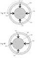
- the adjustment of the contact pressure is preferably carried out with a support bearing having at least one actuator, which is also referred to as a roller lock, wherein in each participating in the adjustment of a roller roller lock or in each participating in the adjustment of a cylinder storage unit preferably more identifiable, individually selectable and thus of the control unit directly or indirectly individually controllable actuators are arranged, wherein the actuated actuators each exert a directed into the interior of their roller lock or their bearing unit radial force, preferably by several actuators radial forces in their vector sum exerted by the roller on the adjacent body rotation Form contact force, wherein the forces exerted by the actuators radial forces are preferably individually and independently adjustable and also provided by the control unit for a desired operating position.
- the actuators can be uniquely identified in each case on the basis of an identifier.
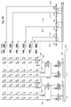
- Actuators connected to a common pressure supply are groupwise, but preferably individually activatable. Due to the arrangement of controllable devices and their respective connection z. B. by means of pressure medium lines are z.
- As the connected to different pressure supplies actuators a particular roller lock or a specific storage unit can be activated jointly, while actuators of another roller lock or another storage unit connected to the same pressure supply remain inactive.
- the contact pressure exerted by a roller engaged on this forme cylinder can be adjusted differently at the two axial ends of this roller.
- control unit z. B. receives the instruction to change the setting of the contact pressure in a selected roll strip by a corresponding input with a control unit belonging to the control unit, which actuator of the roller lock concerned is to be acted upon with what pressure and takes the necessary adjustment in the Pressure setting z.
- the control unit preferably controls valves arranged in the pressure lines, in particular fast-acting, electrically or electromagnetically actuated proportional valves, so that the setting of a setting of an adjusted contact force takes place within a few seconds.
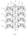
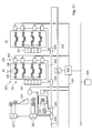
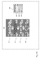
- a printing machine, z. B. web-fed rotary printing press, in particular a multi-color web-fed rotary printing press, has a printing unit 01, in which a web of material 02, short web 02 on both sides simply or in particular successively multiple, z. B. here four times, or several tracks at the same time one or more times are printable.
- the printing unit 01 has a plurality of (in the present case four) vertically stacked double printing units 03 for the two-sided printing in Mattadel rubber operation.
- the double printing units 03 - shown here in the form of bridge or n-printing units - are each formed by two printing units 04, which each have a cylinder 06 formed as a transfer cylinder 06 and cylinder 07 as a forme cylinder; 07, z. B.
- a (double) pressure point 05 is formed in Anstelllage.
- the aforementioned components are designated only at the top double printing unit 03 of Figure 1, wherein the stacked (double) printing units 03; 04 are, however, essentially identical, in particular in the embodiment of the features relevant to the invention.
- the double printing units 03 can - as well as the advantageous feature of the linear arrangement described below - just as well be embodied contrary to the illustration in FIG. 1 as an upwardly opening U unit.
- the printing unit 01 has one or more of the following features, depending on the requirement, the type of machine, the technology used and / or the level of expansion.
- the printing unit 01 or the double printing unit 03 is / are z. B. in the middle, ie in the field of double pressure point (s) 05, operationally divisible run and / or the inking units 08 (and possibly dampeners 09) are formed as already several rolls having modules and used as pre-assembled modules in the printing unit 01 and / or there are printing cylinder 06; 07 different diameter without requirement of bearing bores in the side frame mounted and / or the Cylinder bearings are force-controlled adjustable in linear bearings and / or the axes of rotation of the printing cylinder 06; 07 in print-on are essentially lying in a common plane.
- one or more of the mentioned features are also to be understood advantageously as printing units which do not have printing units 03 designed as double-printing units in the rubber-against-rubber printing, but have printing units 03 working only in straight printing.
- the transfer cylinder 06 of a printing unit then interacts with a counter-pressure cylinder.
- this can optionally be provided, wherein instead of the two cylinders 06; 07 of the second printing unit 04 and the inking unit 08 then only an impression cylinder is used.
- an impression cylinder is used for the arrangement within the side walls then to the other cylinders 06; 07 below apply.
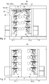
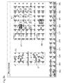
- an advantageous embodiment of the printing unit 01 is shown, which - in principle independent of the also shown there and described in more detail below modular structure of the printing units 04 and / or only for the upper double printing unit 03 indicated by way of example storage units 14 (see Fig. 18) - in the region of their double pressure point (s) 05, operational, ie for setup and maintenance purposes (in contrast to disassembly or disassembly), is divisible executed.
- the two separable parts including cylinder 06; 07, inking units 08 and, if present, dampening units 09
- the printing cylinder 06; 07 more, in particular all the web 02 on the same side printing printing 04 on the same frame or wall section 11; 12 stored.
- the printing cylinder 06; 07 can in principle only one-sided, d. H. be stored flying on only one end frame frame sections 11.
- each partial pressure unit 01.1; 01.2 two front side to the cylinders 06; 07 arranged frame sections 11; 12 provided.
- the two separable parts are hereinafter referred to as partial pressure units 01.1 and 01.2, which the respective frame sections 11; 12 and printing units 04 (printing cylinder 06, 07 and inking units 08) have.
- the partial printing units 01.1; 01.2 are along a direction perpendicular to the axis of rotation of the cylinder 06; 07 movable towards or away from each other by preferably one of both spatially fixed (here partial pressure unit 01.1), d. H. for example, on a floor 13 of the printer room, a fixed space carrier 13, a mounting plate 13 or a mounting frame 13 for the printing unit 01 stationary, and the other (here partial printing unit 01.2) movable relative to the bottom 13 or support 13 or mounting plate 13 or mounting frame 13th (hereinafter carrier 13) is stored.
- both spatially fixed here partial pressure unit 01.1
- carrier 13 for example, on a floor 13 of the printer room, a fixed space carrier 13, a mounting plate 13 or a mounting frame 13 for the printing unit 01 stationary, and the other (here partial printing unit 01.2) movable relative to the bottom 13 or support 13 or mounting plate 13 or mounting frame 13th (hereinafter carrier 13) is stored.
- the outer frame sections 12 in mutually corresponding, in non-illustrated bearing elements of the frame portion 12 and the carrier 13, z. B. together a linear guide 15 forming, stored.
- These can be designed as running in rails rollers or as a sliding or rolling body mounted mutually associated linear guide elements.
- the wall sections 11; 12 are formed in such a way that, in their operating position A (FIG. 2), they are complementary in shape to each other on their mutually facing side in a complementary manner to one another and, when moved together, form a substantially closed side front at their parting lines or joint lines.
- FIG. 3 shows a maintenance position B of the printing unit 01 (without the bearing units 14 indicated in FIG. 2), the relative position of the partial printing units 01.1; 01.2 each other by moving the frame sections 12 is effected.
- the relative position can in principle be achieved in another embodiment by both partial pressure units 01.1; 01.2 or their frame sections 11; 12 are movably mounted.
- Shaping and transfer cylinder 07; 06 are in a first, in Figs. 1 to 3 previously shown format design preferably with a bale width of at least four, z. B. four or for particularly high product output six, juxtaposed standing printed pages in newspaper format, especially in broadsheet format formed.
- the cylinder 06; 07 on a circumference, which essentially corresponds to two consecutively arranged printed pages in a newspaper format.
- this advantageously has two circumferentially offset by 180 ° to each other channels for receiving the printing plates, which preferably over the entire effective ball length continuously are formed.
- the forme cylinder 07 can then be equipped with four or six printing forms side by side and two printing plates in succession.
- the transfer cylinder 06 has a double large format (two newspaper pages in the scope behind each other) in one embodiment z. B. only one channel for receiving one or more juxtaposed blankets, which is preferably formed continuously over the entire effective bale length.
- the transfer cylinder 06 can then be equipped with a continuous over the bale length and extending over substantially the full circumference or with two or three over substantially the full circumference reaching blankets side by side.
- this two or three blankets can have side by side, wherein the respective adjacent to each other are offset by 180 ° in the circumferential direction.
- These mutually offset blankets can be held in two or three channel sections, which are also adjacent to each other in the longitudinal direction of the cylinder 06, the adjacent channel sections in the circumferential direction, however, are mutually offset by 180 °.
- the inking units 08 or cylinder units 17 formed of bearing units 14 and the respective cylinder 06, or preferably both the inking units 08 are initially independent of the part or separability as well as the cylinder units 17 as modules, d. H. designed as structurally considered pre-assembled units.
- the running as modules inking 08 have z. B. a separate frame 16 and a frame structure 16, in which several functional parts, here at least three, especially all rollers and a color source or ink supply (chamber doctor blade, ink fountain, applicator nozzles, etc.) of the inking unit 08, even without connection to the side frame 11; 12 of the printing unit 01, already their firmly defined position to each other obtained and, for example, pre-assembled and a total of the printing unit 01 can be introduced.
- the frame construction 16 or the frame 16 can be embodied, in particular, as two side frames which are arranged at the ends on the rollers and which are interconnected, for example, by at least one traverse (not shown) and / or a base.
- the functional parts of the module receiving frame 16 is fixed during assembly (cohesively or fomschlüssig solvable) with the side frame 11; 12 of the printing unit 01 connected. If the printing unit 01 is designed to be partially or separable in the manner described above, the inking units 08 designed as modules will be assembled on assembly with the respective frame or wall sections 11; 12 - cohesive (welding) or positive releasable (screw) - connected.
- the total side frame on one side of the printing unit 01 or a total side frame of a partial printing unit 01.1; 01.2 then sets in several pieces - a cylinder 06; 07 receiving side frame 11; 12 and partial sub-frames of the inking units 08 comprising - together.
- Detachable here means no operational solubility but only a disassembly with regard to a disassembly of the printing unit 01 or a removal / replacement of the inking unit 08.
- a cylinder units 17 running modules (see below to Fig. 17 and 18) have z. B. a cylinder 06; 07 with pin 63; 64 and one already on the pin 63; 64 pre-loaded (biased and / or preset) storage unit 14 on. Bearing unit 14 and cylinder 06; 07 get before their insertion into the printing unit 01 their firmly defined position to each other and are collectively in the printing unit 01 introduced.
- FIG. 4 illustrates a system of a modular printing unit 01, which, however, can basically be designed to be both divisible (as illustrated) and indivisible. In the latter case, that would be the cylinder 06; 07 receiving side frame 11; 12 not in two parts but one-piece and fixed space in the printing arranged.
- the divisible variant as shown.
- the frame sections 11; 12 can be embodied as essentially continuous wall sections, in each case in one piece and flat, or in each case be kept slim for the purpose of easier construction and / or better accessibility of the units, as shown, and possibly per side frame for stabilization with additionally one or more vertically supporting supports (FIG. not specifically referenced).
- a transfer cylinder 06 As also shown in Fig. 4, as a transfer cylinder 06, a transfer cylinder 06a with a circumference of two stationary printed pages, especially newspaper pages in broadsheet format, (double size) or a transfer cylinder 06b with a circumference of a print page, especially newspaper page in the broadsheet Format (simply large) to be used.
- the assembly with cylinders 07a a circumference of two stationary pages, especially newspaper pages, or simple scope (form cylinder 07b), ie a print page, in particular newspaper page in broadsheet format, on the periphery possible.
- the printing unit 01 with form cylinders 07 simply large format (a newspaper page in the scope) has this advantageously in the circumferential direction considered a channel for receiving the printing plates, which is preferably formed continuously over the entire effective bale length.
- the forme cylinder 07 can then be equipped with four or six printing plates next to each other.
- the transfer cylinder 06 has a simple large format (a newspaper pages in the scope) in one embodiment z. B. only one channel for receiving one or more juxtaposed blankets, which is preferably formed continuously over the entire effective bale length.
- the single-circumference transfer cylinder 06 can then be equipped with a continuous over the bale length and extending over substantially the full circumference or with two or three over substantially the full circumference reaching blankets side by side.
- the optional configuration with (eg, single large or double-sized) cylinders 06; 07 with scopes for different printed page formats, eg. As newspaper formats, with divergent circumferences possible.
- this modular construction is particularly favored, since for this purpose the exact position and geometry of the cylinders 06; 07 bearing bores for the accurate fit of three- or four-ring bearings with z. B. eccentrics in the side frame 11; 12 must be provided.
- the printing unit 01 is exemplified by cylinders 06a; 07a double circumference executed.
- cylinders 06a When equipped with simple large cylinders 07b these can for reasons of increased stability (as below to Fig. 7, 9, 13) with double-size transfer cylinders 06a or space-saving with equally simple transfer cylinders 06b cooperate.
- inking units 08 of different types depending on the customer's requirements.
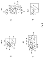
- the various types of inking can, as shown in Fig. 4 Short inking 08.1, single roll inking 08.2 z. B. with two Reibzylindern (eg., From the newspaper printing) or roller inking 08.3 with two color trains and z. B. three Reibzylindern (eg., From the commercial printing).
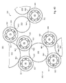
- the inking unit 08 which is designed as a short inking unit 08.1 of a first variant (FIG. 6a), has a central roller 26 with scrapers or cups, for example a bottle.
- a central roller 26 with scrapers or cups, for example a bottle.
- an anilox roller 26 which relates the color of an inking device 27, in particular a chambered doctor blade 27 (or even a roller, not shown from an ink fountain) and at least one, preferably at least two, roller (s) 28, z. B. applicator rollers 28, z. B. an inking roller 28, in particular with a soft surface, emits to the printing forme of the forme cylinder 07.
- the central roller 26 with two other soft rollers 29, z. B. paint or applicator rollers 29 together.
- the inking device 27 obtains its color, for example, from a paint reservoir 32, in particular via a pumping device, not shown, in which excess paint can also drain.
- the anilox roller 26 by its own, of the cylinders 06; 07 independent drive motor driven by rotation.
- the remaining rollers 28; 29; 31 are preferably driven by friction.
- the traversing movement can be carried out with increased demand for variability by its own drive means, or as provided here with reduced effort, by a rotational movement in axial movement reshaping transmission.
- the inking unit 08 which is designed as a one-time roller inking unit 08.2 (also "long inking unit", FIG. 6b)), has (at least) two application rollers 28 which apply the ink to the printing plate and convey the ink over a printing plate-near roller 33, in particular iridescent friction roller 33 or A friction cylinder 33 (eg with a hard surface), a roller 34, in particular a color or transfer roller 34 (eg with a soft surface), an iridescent friction roller 33 or distribution cylinder 33, another color or transfer roller 34 (For example, with a soft surface), a roller 37, in particular film roller 37 and a roller 36, in particular ductor or dipping roller 36 receives from an ink fountain 38.
- a printing plate-near roller 33 in particular iridescent friction roller 33 or A friction cylinder 33 (eg with a hard surface)
- a roller 34 in particular a color or transfer roller 34 (eg with a soft surface)
- Dipping and film roller 36; 37 can also be replaced by another ink feed or metering system (eg pumping system in the pumping inking unit, or lifter system in the lifting inking unit).
- the distribution cylinder 33 jointly or individually, by a separate, from the cylinders 06; 07 independent drive motor driven by rotation.
- the roller 36 is preferably, and optionally further provided for the film roller 37, a separate rotary drive motor.
- the traversing movement of the distribution cylinder 33 can, with increased demand for variability, jointly or individually, by a separate drive means, or as provided here with reduced effort, done by a rotational movement in axial movement forming gear.
- An advantageous further embodiment of -. B. also executed in the manner of a module - single inking 08.2 is set out below in the description of Fig. 31 to 35.
- the inking unit 08 which is designed as a two-row roller inking unit 08.3 (FIG. 6c), has at least three applicator rollers 28 which apply the ink to the printing form and which color over a first inking train with a first distribution cylinder 33, a soft inking roller 34 and a hard ink fountain Transfer roller 39, and a second ink draw with a second distribution cylinder 33 from a common soft ink roller 34 ago, a form cylinder distant distribution cylinder 33, another soft ink roller 34, a film roll 37 and a ductor roller 36 from a color box 38 receives.
- Like o. G can here and ductor roller 36; 38 by another o. G. Replaced color supply or - dosing.
- the three distribution cylinders 33 are distributed cylinders 33, jointly or individually, by a separate, from the cylinders 06; 07 independent drive motor driven by rotation.
- a separate rotary drive motor is also provided for the ductor roller 36.
- the traversing movement of the distribution cylinder 33 can be carried out with increased demand for variability, jointly or individually, by its own drive means, or as provided here with reduced effort, by a rotational movement in axial movement reshaping transmission.
- this inking 08.3 can also be used for newspaper printing, but is preferably provided when configuring the printing unit for commercial printing.
- a short inking unit 08.4 (also "anilox inking unit”), this only has a large, in particular a size of the forme cylinder 07 corresponding applicator roll 28 ', which of the anilox roller 26 (in a variation just as large) receives the color and from the paint application device 27, z. B. a doctor blade system 27, in particular the chambered doctor blade 27, is colored.
- This inking unit 08.4 may be provided equally in printing units 01 configured for newspaper printing, in particular for commercial printing, because of its low tendency to duplicate (due to the 1: 1 ratio between applicator roll 28 'and forme cylinder 07).
- the inking units 08.x of the same type x each for the different formats of the forme cylinder 07a; 07b, as indicated in Fig. 4, various embodiments may be provided.
- the different formats can be operated in a modular way.
- the inking units 08.x the same type are then advantageously constructed in the same manner, but may differ in the overall geometric orientation or at least the applicator rollers 28; 28 '.
- the short inking unit 08.1a (FIG. 2) or the short inking unit 08.1b (FIG. 7).
- the side frames 11; 12 for a plurality of inking units 08 of the same type and / or different types a same the inking unit 08 supporting pad, recess or stops on.
- they can be designed in their shape so that they can accommodate several inking units 08 of the same type and / or different types.
- inking 08 usable Einitatikanten or bearing surfaces or in the side frame 11; 12 after production already several different, for different inking 08 be prepared each fitting Ein cognitivekanten / contact surfaces.
- a traverse 23 is indicated, on which the respective inking unit 08 can be placed or suspended there.
- the inking units 08 may also be stacked on one another and / or additionally secured or fastened to the vertical supports.
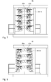
- the printing unit 01, z. B. for newspaper printing in an advantageous first embodiment with short inking units 08.1 (Fig. 6a) equipped. Since the forme cylinder 07a is designed there with double format, the printing unit 01 z. B. the corresponding short inking 08.1a.
- the printing and inking units 04; 08 are here for the "dry offset” or “waterless offset printing” executed, d. H. the execution of printing plate and inking unit 08 is such that no dampening solution and thus no dampening unit 09 is provided.
- Fig. 7 shows in a second embodiment, for. B. for the newspaper printing, the placement of the printing unit 01 in the dry offset, with short inking 08.1b for the case simply large cylinder 07b.
- Fig. 8 and Fig. 9 show the printing unit 01, z. B. for the newspaper printing, in a third and fourth embodiment equipped with admirghigen roller inking 08.2a; 08.2b - once with double large cylinders 07a and in the second case with single cylinders 07b, each in dry offset.
- Fig. 10 shows the printing unit 01, alternatively for the newspaper printing or commercial printing, however, indicated in a common representation, in a fifth, sixth and seventh embodiment equipped with the second variant of Kurzfarbtechnike 08.4 - with double-size cylinders 07a, with simple large cylinders 07b or with a form cylinder 07c described below for commercial printing, each in dry offset.
- the application roller 28 '(FIG. 6d) preferably has in each case the circumference of the assigned forme cylinder 07a; 07b; 07c on.
- Fig. 4 and Fig. 11 a) is a solid line with a first embodiment of the dampening unit 09 as a dampening 09.1 with at least three rollers 41; 42; 43 shown.
- the dampening unit is 09.1 as so-called.
- Contactless dampening 09.1, in particular Sprühfeuchttechnik 09.1 executed, wherein on a last roller 43 of the dampening unit 09, the dampening solution is transferred without contact from a fountain solution source 44 ago. This can be done, for example, by contactless spinning, contactless brushing or otherwise, but preferably by spray nozzles of a spray bar 44.
- the distribution cylinder 42 by its own, of the cylinders 06; 07 independent drive motor driven by rotation, wherein the two rollers 41 and 43 are driven by friction.
- the roller 43 be provided a separate rotary drive motor.
- the traversing movement of the friction cylinder 42 can take place by means of its own drive means or, as provided here with reduced effort, by means of a gearbox which converts its rotational movement into axial movement.
- FIG. 11a shows in the illustration, taking into account the dashed circle, a particularly advantageous development of the three-roll dampening unit 09.1 from FIG. 11a), wherein, in contrast to the dampening unit 09.1 according to FIG. 11a), the roller 42 is provided with a color-friendly or color-compatible oleophilic surface 45 (ie wetting angle with corresponding fluid, in particular the color, less than 90 °) z.
- B. of rubber or plastic (eg., A polyamide material) is formed.
- the lateral surfaces of all three rollers 41; 42; 43 of the dampening unit 09 with a color-friendly or oleophilic surface 45 i.e., contact angle of wetting with corresponding fluid, in particular the color, less than 90 °
- this middle roller 42 can be designed as a roller 42 fixed in the axial direction, that is to say it can not be changed.
- the roller 42 is formed with a soft surface, in particular made of rubber, can be a rotatory positive drive of the rollers 41; 42; 43 omitted and all of them only by friction from the forme cylinder 07 forth - roller 41 by forme cylinder 07, roller 42 by roller 41 and roller 43 by roller 42 - be driven.
- a positive drive provided in conjunction with FIGS. 26 to 30 via its own drive motor 132 or a drive connection 141 is completely eliminated in this embodiment. None of the rollers 41; 42; 43 has in addition to the friction on an additional rotary positive drive. If the roller 42 is designed as a changeable roller 42, then for the forced traversing motion either a motorized traversing drive or a gear which converts the rotational movement into an axial movement can take place.
- the middle roller 42 of the three rollers 41; 42; 43 of the Dampening roller pull a color-friendly upper or lateral surface 45 made of plastic, z.
- plastic z.
- this roller 42 by its own, from the printing cylinder 06; 07 mechanically independent drive motor 132 or a drive connection 141 from the printing unit 04 and / or inking unit 08 ago (see below to Fig. 26 to 30) is rotatably positively driven.
- the roller 42 is formed as a changeable roller 42, it may again be provided either for the forced traversing movement either a motorized traversing drive or a transmission which converts the rotational movement into an axial movement.
- a “soft” surface is here to be understood an elastically yielding surface in the radial direction, i. H. with a modulus of elasticity in the radial direction of preferably at most 200 MPa, in particular less than or equal to 100 MPa.
- the roller 43 receiving the dampening solution from the fountain solution source 44 and / or the roller 42 subsequently arranged in the roller train in the direction of the forme cylinder 07 preferably has a jacket surface with a hardness in the range between 55 ° and 80 ° Shore A.
- the roller 41 applying the dampening solution to the forme cylinder 07 preferably has a jacket surface with a hardness in the range between 25 ° and 35 ° Shore A.
- Fig. 4 and Fig. 11 b) is a second embodiment of the dampening unit 09 as Griffinfeuchtwerk 09.2 (film dampening unit, lifter, cloth or brush dampening unit) with a total of three rollers 47; 48; 41 (28) between dampening solution master 46 and forme cylinder 07 in series.
- the dampening 09.2 is designed as a so-called.
- an iridescent transfer cylinder 48 transmits to at least one applicator roller 41 with a soft surface.
- the at least one application roller 41 is shown only by dashed lines, since they are either only a dampening unit 09 associated (not shown in Fig. 14), or as shown in Figure 14 a simultaneously the inking and dampening 08; 09 assigned, and z. B. optionally only dampening solution or fountain solution and color leading, common applicator roller 28 (41) may be. If the dampening unit 09.2 (FIG. 11b) has a total of three rolls, as illustrated, then the dip roll 47 is preferably designed with a soft surface.
- four-roller contact dampening 09.2 joins the soft roller 47 a fourth roller, not shown with z. B. hard surface, which dips instead of the roller 47 in the fountain solution box 46.
- a fourth roller by its own, of the cylinders 06; 07 and the other inking rollers independently driven drive motor rotatably, wherein the roller 41 is driven by friction.
- a separate rotary drive motor can also be provided for the distribution cylinder 48.
- the traversing movement of the friction cylinder 48 can take place by means of its own drive means or, as provided here with reduced effort, by means of a gearbox which converts its rotational movement into axial movement.
- the dampening unit 09 can either be designed as a separate module (that is to say, largely preassembled in a separate frame) or can be integrated into the module "inking unit 08" in an advantageous embodiment for the case of wet offset.
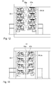
- Fig. 12 and Fig. 13 now show the printing unit 01, z. B. for the newspaper printing, in an eighth and ninth embodiment equipped with einzugigen roller inking 08.2a; 08.2b - once with double-sized cylinders 07a (Fig. 12) and in the second case with simply large cylinders 07b (Fig. 13), in contrast to Fig. 8 and 9 but in wet offset with the arrangement of dampening 09, here z. B. three-roll spray dampening 09.1.
- the above-mentioned double-sized, a circumference of two printing pages designed as a newspaper pages 07a cylinder preferably have in Circumferentially one behind the other two channels for fixing two circumferentially arranged one behind the other, each impression side long pressure forms.
- the two in an advantageous embodiment in the axial direction continuous channels or the two groups of a plurality of axially adjacent channel sections and / or the corresponding clamping devices are designed in such a way that in the axial direction next to each other at least two individual, one or two zeitenclose printing forms fixed are.
- the forme cylinder 07a is then in an operating situation with two pressure side long pressure plates in the circumferential direction and a plurality, z. B.
- a circumference of a designed as a newspaper page printing page having cylinder 07b preferably have in the circumferential direction, only a channel for fixing the ends of an impression-side printing plates.
- the advantageously continuous channel or a group of several axially juxtaposed channel sections and / or corresponding clamping devices are designed in such a way that in the axial direction next to each other at least two individual, one or two newspaper page width printing forms can be fixed.
- the forme cylinder 07b is then in an operating situation with a pressure side length, in particular newspaper page length printing form in the circumferential direction and a plurality, z. B. two, three, four or even six, in each case at least impression widths, in particular newspaper page wide printing forms in the longitudinal direction. It is also impression side width and two- or even dreidurcktimebreite printing forms mixed next to each other or only several two- or even dreidruckinbreite printing forms next to each other on the form cylinder 07b may be arranged.
- the printing unit 01 is not only the newspaper printing but also the printing of a format deviating from the newspaper printing and / or a printing quality deviating from the newspaper printing.
- This is reflected for example in the printing unit 01 or the printing units 04 by special design of the inking and / or dampening unit 08; 09, by a special embodiment of the printing cylinder 06; 07, by special design of the lifts (printing plates, blankets) on the cylinders 06; 07, by a u. U. significantly different paper web thickness and / or quality, and / or down by a the printing process in an advantageous embodiment downstream drying stage.
- Such a printing unit 04 then has forme cylinder 07c with only one, on the barrel length of the forme cylinder 07c continuous channel on the periphery and carries a single, to the full extent and the entire length of the bale reaching printing form.
- the usable bale length corresponds for example to four, six or even eight standing printed pages, z. B. in DIN A4 format (or a number of this length corresponding pages of a different format), in the transverse direction next to each other and two such printed pages in the longitudinal direction one behind the other. Accordingly, the full printing form has all the printed pages.
- the transfer cylinder 06c has only a continuous channel and only a single full-scale elevator, z. B. a blanket, in particular a z. B.
- a circumference of the forme cylinder 07c, and thus a maximum printing length on the web 02, amounts to, for example, 520 to 650 mm, in particular 545 to 630 mm. The same applies preferably also to the corresponding transfer cylinder 06c.
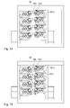
- Fig. 14 and Fig. 15 now show the printing unit 01, z. B. for commercial printing, in a tenth and eleventh design equipped with cylinders 07c for commercial printing and two-roll inking units 08.3 - once waterless and in the second case in wet offset with the arrangement of dampening 09.2, here z. B. with three-roll film works 09.1 wherein the applicator roller 41 at the same time, z. B. as the fourth applicator roll 28, the inking unit is associated with 08.3.
- the printing unit 01 has, as in FIG. 2, short inking units 08.1 or one-color inking units 08.2, which, however, have cylinders 06c; 07c of the commercial print together.
- the modular structure of the inking units 08 and the printing unit 01 with respect to the inking units 08 allows the structure of the inking units 08.x of a certain type except for the format-dependent (double, simple, commercial etc.) arrangement / execution of the applicator rollers 28 the same may be that the Reibzylinder thoroughlymesser at least one type (with the exception of inking 08.4) in many or even all formats are the same.
- the inking unit 08 eliminates a coupling to the cylinders 06; 07, which further favors modularity.
- Drive and gearbox can be designed independently of format.
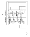
- the modules having printing units 01 of Figures 2, 7 to 10 and 12 to 15 can advantageously as indicated by the dividing line in the sense of Fig. 2 and 3 with divided or divisible frame walls 11; 12 or in principle also with conventional, closed side frames 11; 12 executed.
- the side frame 11; 12 not divisible in the manner that the printing cylinder 06; 07 are separated at the pressure point 05, but it is the printing cylinder 06; 07 in or on a common side frame 11; 12 stored undivided, while on both sides of the inking units 08 receiving wall sections 49 in an operating position A (not shown) or a maintenance position B (shown) can be brought.
- the division takes place here between forme cylinder 07 and inking and possibly dampening unit 08, 09.
- the inking units 08 (and possibly existing dampening units 09) shown here only schematically may be accommodated as modules in the wall sections 49 in the sense of the above-described modular design (FIG 24, left side).
- Fig. 24 shown on the right, consisting of the inking units 08 and the wall sections 49 assembly listed in total as a pre-assembled module.
- the middle parts side frame 11, 12
- corresponding cylinder assembly and the side parts including the inking units 08 can then be combined.
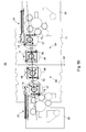
- a handling device 24 can be provided to support the printing form change.
- the handling device 24 is designed as at least partially automatic or even fully automatic printing plate changer 24.
- the handling device 24 has a shaft-like receiving region 53 for receiving printing forms between a lower guide 51, which is preferably flat or strut-like or frame-shaped, and an upper guide 52.
- the receiving area 53 is configured in a basic configuration, preferably in the sense of modularity, in such a way that from the space in principle at least except for optionally optional non-supporting additional installations - both wide, over the length of the bale reaching printing forms as well as several one- or two-page wide juxtaposed printing forms are to be included in this.
- non-load-bearing and / or removable attachments could include side guides for intermediate printing dies in the case of multiple on the form cylinder 07a; 07b to be arranged side by side printing forms.
- a template area 54 for newly Anlagennde printing forms is also advantageous for a template area 54 for newly Anlagennde printing forms.
- This can be bounded by the upper guide 52 and possibly by a cover 56 - flat or braced - upwards also shaft-like and possibly covered against contamination.
- the guide 52 supporting the new printing forms should preferably be flat or at least braced in such a way that the printing form does not undergo deflection.
- the handling device 24 has a side register means 57, which in one embodiment only a lateral stop 58, z. B. side stops 58 for a single continuous printing form, and in another embodiment, a plurality of axially spaced stops 58 Internal Print forms.
- a number of m side stops 58 in another embodiment, although the same number n of side stops 58 can be brought into the Zuliteweg in different operating positions, but these are spaced from each other in the first situation different ways, that is provided for a different printing form width or printing page width.
- generally only one side stop 58 (for the commercial printing form) and in another operating mode a defined number n can be brought into the pull guide path in an operating situation.
- the part of the handling device 24 having the receiving region 53, the original region 54 and the side register device 57 is preferably designed as a preassembled module or component, hereinafter referred to as a magazine 59, which Total is used depending on the equipment requirement to the printing press in the printing unit 01.
- This magazine 59 preferably has a drive mechanism, not shown, z. B. one or more carriages or belt conveyors - and a corresponding control to promote the ab- and réelleplattenden printing plates and allows a fully automatic printing form change.
- this magazine 59 also means for pressing and / or guiding the printing plates during the change -.
- adjustable roles - have.
- the handling device 24 is designed in a modular manner, on the one hand the magazine 59 enabling a fully automatic printing form change and, on the other hand, a pressing device 61 with -. B. via fluid-actuated means - adjustable rollers 62 is provided.
- the pressing device 61 alone supports both a fully automatic printing form change with magazine 59 and a semi-automatic (partial manual) printing plate change without magazine 59 and is in contrast to the magazine 59 preferably provided in principle in the printing unit 01.
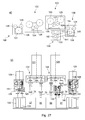
- the cylinder 06; 07 in storage units 14 on the side frames 11; 12 rotatably store, which the escape of the side frames 11; 12 do not penetrate and / or the cylinder 06; 07 with her bale 67; 68 including their pin 63; 64 a length L06; L07, which is less than or equal to a clear width L between the printing cylinder 06; 07 to both end faces supporting side frames 11; 12 (Fig. 17).
- all four printing cylinder 06; 07 (but at least three) has its own storage unit 14, in which the on / off mechanism is already integrated. It can also for three of the four cylinders 06; 07 the bearing / Abstellmechanismus having bearing units 14 and be provided for the fourth bearing units 14 without on / off mechanism.
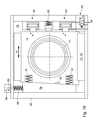
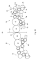
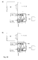
- FIGS. 18 and 19 show a bearing unit 14, preferably based on linear travel paths, in schematic longitudinal and cross-section.
- the on / off mechanism integrating bearing unit 14 has in addition to a bearing 71, z. B. radial bearing 71, for example, a cylindrical roller bearing 71, for rotatably supporting the cylinder 06; 07 storage means 72; 73 for a radial movement of the cylinder 06; 07 - for pressure on or pressure off - on.
- the bearing unit 14 (after mounting the bearing unit 14 frame-fixed) carrier-resistant bearing elements 72 and the movable against these bearing elements 73.
- the carrier-fixed and movable bearing elements 72; 73 are as co-operating linear elements 72; 73 and formed together with corresponding sliding surfaces or intermediate rolling elements in total as a linear bearing 70.
- the linear elements 72; 73 take in pairs a radial bearing 71 receiving bearing block 74, z. B. carriage 74 between them.
- Bearing block 74 and the movable bearing elements 73 may also be made in one piece.
- the carrier-fixed bearing elements 72 are arranged on a carrier 76, which in total with the side frame 11; 12 is connected or is.
- the carrier 76 is designed for example as a support plate 76, which, for example, at least on a drive side, a recess 77 for the passage of a shaft 78, z. B.
- the frame wall 11; 12 on the drive side preferably has a recess or an opening for a drive shaft 78.
- On the opposite side of the drive side does not necessarily have a recess 77 or a recess in the side frame 12; 11 may be provided.
- a length of the linear bearing 70 is smaller than a diameter of the associated printing unit cylinder 06 in the direction of adjustment S; 07th
- the clamping device 66 is here for example as z. T.
- the coupling can also in other ways, for. B. in the circumferential direction having a positive connection, be executed.
- the shaft 78 is formed by a recess in the side frame 11; 12 out, which is sufficiently large for the movement of the shaft 78 is dimensioned together with the bearing block 74 and which z. B. is formed in the manner of a slot.
- a cover 69 may be provided with a slot covering the collar, which z. B. with the bearing block 74, but not connected to the shaft 78.
- one of possibly a plurality of serially arranged coupling 148 is connected to the cylinder-distal end of the shaft 78 by a rotationally fixed connection 75, eg. B. a clamping element 75, coupled.
- a rotationally fixed connection 75 eg. B. a clamping element 75
- directly the gear 150 with drive motor 121 without angle and / or Offset compensating coupling 148 can be coupled to the shaft 78.
- the drive motor 121 is not fixed to the frame, but arranged cylinder-tight and is connected to the cylinder 06; 07 moved.
- the pin 64 is preferably provided with a device for axially moving the cylinder 07, d. H. with a side register drive 201, coupled ( Figure 36).
- the axial drive comprises a spindle 203, in particular with at least one threaded portion 205, a rotatably connected to the spindle 203 spur gear 204, a pinion 206 and the pinion 206 driving motor 207.
- the threaded portion 205 acts with a bearing block fixed internal thread 208, z. B. an internal thread 208 of a bearing block 74 connected to the pot 209, and causes the rotation of the spindle 203 an axial movement thereof together with the shaft 78 (via the thrust bearing 202) and pin 63; 64.
- the thrust bearing 202 allows relative rotation between the shaft 78 and spindle 203, but is formed with respect to an axial direction of the cylinder 07 pressure and tension. This is done via a arranged on the shaft 78 disc 211, which is supported on both sides, for example via rolling elements 212, wegbe advocacy by spindle-fixed stops 210 in both directions.
- An adjustment of the page register is now carried out by the motor 207 via a control device, not shown.
- the motor 207 may either itself via a -. previously calibrated accordingly - motor-internal position feedback feature, or there is a position feedback to the controller via a sensor, not shown, for. B. a suitably calibrated rotary potentiometer, which is coupled to a rotating component of the axial drive.
- linear bearings 70 in such a way that the cooperating bearing elements 72; 73 both on the unit storage unit 14 - and not a part of the Side frame 11; 12 of the printing unit 01 - are provided, allows pre-assembly and pre-adjustment or adjustment of the bearing voltage.
- the advantageous arrangement of the two bearing block 74 encompassing linear bearing 70 allows a backlash-free setting, as opposed to the two linear bearings 70 in such a way that the bearing preload and the bearing forces an essential component in a direction perpendicular to the axis of rotation of the cylinder 06; 07 learn or record.
- the linear bearings 70 are thus adjustable in the direction to which it is at play-free positions of the cylinder 06; 07 also arrives.
- non-penetration and the above definition with respect to the inside width L should be understood in a broader sense to mean that, at least in the region of the intended end position, the cylinder 06; 07 and at least on a continuous path from a frame edge to the location of the end position such a "non-penetration" is present, so that the cylinder unit 17 of an open, between the two end-side side frames 11; 12 lying side without tilting, d. H.
- the bearing units 14 are in the manner on the inner walls of the sokar 11; 12 arranged that the cylinder 06; 07, in particular their bearing units 14 on the cylinder side by the side frame 11; 12 are supported, which has static and mounting advantages.
- the linear bearings 70 (72, 73) which can be seen in FIGS. 18 and 19 thus each have pairings of corresponding cooperating bearing means 72 and 73 or their guide or effective surface areas, designed as sliding surfaces (not shown) or with rolling elements 65 arranged therebetween ,
- at least one of the two advantageous two linear bearings 70 of a bearing unit 14 is designed such that the two corresponding bearing means 72 and 73 each have at least two guide surfaces 72.1; 72.2; 73.1; 73.2, which lie in two mutually inclined planes.
- the two guide surfaces 72.1; 72.2; 73.1; 73.2 (or their planes E1, E2) of the same bearing means 72; 73 are z.
- the two guide surfaces 73.1; 73.2; 72.1; 72.2 of the cooperating bearing means 73; 72 are complementary in shape. At least one of the two pairings of cooperating guide surfaces 72.1; 72.2; 73.1; 73.2 is parallel to a plane E1, which has a component not equal to zero in the radial direction of the cylinder axis and thereby prevents the degree of freedom of movement in a purely axial direction of the cylinder.
- both pairings lie to planes E1; E2, which both have a component not equal to zero in the radial direction of the cylinder axis, but in reverse inclination against the cylinder axis and thereby prevent the degree of freedom of movement in both axial directions of the cylinder.
- a section line of the two planes E1; E2 is parallel to the direction S
- the inclined active or guide surfaces 72.1; 72.2; 73.1; 73.2 are arranged such that they a relative movement of the bearing parts of the linear bearing 70 in the axial direction of the cylinder 06; 07, ie the bearing is "tied off” in the axial direction.
- the linear bearings 70 both a cylinder 06; 07 frontally associated bearing units 14 two mutually arranged pairs of cooperating guide surfaces 72.1; 72.2; 73.1; 73.2.
- at least one of the two radial bearings 71 of the two bearing units 14 a slight bearing clearance .DELTA.71 in the axial direction.
- the frame-fixed bearing means 72 encompass here the bearing block 74 arranged between them.
- the frame-fixed guide surfaces 72.1; 72.2 of the two linear bearings 70 thus partially surround the guide surfaces 73.1; 73.2 of the bearing block 74 with respect to an axial direction of the cylinder 06; 07th
- bearing unit 14 For correct placement of the bearing units 14, and cylinder units 17 together with bearing unit 14, mounting aids 89, z. B. dowel pins 89 in the side frame 11; 12 may be provided, to which the bearing unit 14 of the fully assembled cylinder unit 17 is aligned, before they by releasable retaining means 91, z. B. screws 91, or even cohesively by welding to the side frame 11; 12 are connected.
- corresponding means 92 e.g. B. clamping screws 92 may be provided (Fig. 18).
- the bearing unit 14 - at least to the cylinder side - by a cover 94 largely protected against contamination or even encapsulated executed as a unit.
- Fig. 18 is schematically the cylinder 06; 07 with pin 63; 64 and a preassembled storage unit 14.
- This module can thus be preassembled between the side frames 11; 12 of the printing unit 01 used for easy installation and attached to designated locations.
- the effective inner surface of the radial bearing 71 and the outer effective lateral surface of the pin 63; 64 be cylindrical instead of tapered, since both the assembly of the bearing unit 14 on the pin 63; 64 as well as the setting of the bearing clearance outside the printing unit 01 can be done.
- the storage unit 14 can be shrunk, for example.
- the mountable as a whole unit is advantageous in the manner of an optionally partially open housing of z. B. the carrier 76, and / or z.
- a frame in Fig. 19 without reference numerals, for example, the four the bearing unit 14 to all four sides outwardly bounding plates
- the cover 94 Figure 18.
- the frame-fixed bearing elements 72 are arranged substantially parallel to one another and define a setting direction (FIG. 19).
- Pressing is effected by moving the bearing block 74 in the direction of the pressure point by means of a force F applied to the bearing block 74 by at least one actuator 82, in particular by a force-controlled or force-defined actuator 82, by means of which a defined resp . definable force F in print-on direction on the bearing block 74 can be brought (Fig. 19).
- the decisive for the color transfer and thus the print quality, among other things, line force in the nip points is not by a travel, but by the balance of power between the force F and between the cylinders 06; 07 resulting line force F L and the resulting equilibrium defined.
- cylinder 06; 07 employed in pairs by the bearing block 74 is acted upon by the corresponding set force F via the / the actuator (s) 82.
- At least the two middle of the four cylinders 06 - or in other words, at least all of the two outer cylinders 07 different cylinder 06 at least during a period of time Setting in a defined position, advantageously in the Anstelllage found by the equilibrium of forces, can be fixed or at least wegbegrenzbar.
- bearing block 74 even during operation - at least in one direction away from the pressure point against a force, for. B. spring force, in particular a definable force, is movably mounted. This is - in contrast to the pure travel limit - on the one hand, a maximum line force when working together cylinder 06; 07 defined, and on the other hand a yielding, for example, in a web break with subsequent winder on the cylinder 06; 07, allows.
- the bearing unit 14 - At a pressure point 05 facing side, the bearing unit 14 - at least during the adjustment process - a movable stop 79, which the Travel range to the pressure point 05 limited.
- the stop 79 can be moved in such a way that the stop surface 83, which acts as a stop, can be varied along the direction of adjustment at least in one region. It is thus an adjustment device (adjustable stop 79) provided in an advantageous embodiment, by means of which the position of a pressure near the end position of the bearing block 74 is adjustable.
- the position of a pressure near the end position of the bearing block 74 For Wegbegrenzung / adjustment serves z. B. a wedge drive described below.
- the placement of the stop 79 can basically be done manually or via an actuator 84 (see below).
- a holding or clamping means not shown in Fig. 18 and 19 is provided by means of which the stop 79 can be set in the desired position.
- at least one resilient element 81, z. B. spring element 81 which applies a force F R from the stop 79 in a direction away from the bearing block 74.
- the spring member 81 causes pressure-off in the event that the bearing block 74 is not prevented from moving in any other way.
- the applied force F, the restoring force F R and the position of the stop 79 is selected such that no substantial force AF is transferred between the stop 79 and the abutment surface of the bearing block 74 in an abutment position such that
- the contact force between the cylinders 06; 07 substantially determined by the voltage applied by the actuator 82 force F.
- line force in the nip points is not primarily defined by a travel, but at quasi-free stop 79 by the force F and the resulting balance. Basically, after finding the basic setting with the appropriate forces F, a removal of the stop 79 or a corresponding fixation, which is effective only during the basic adjustment, would be conceivable.
- the actuator 82 can be embodied as any desired actuator 82 applying a defined force F.
- the actuator 82 is designed as actuatable by pressure medium actuating means 82, in particular as a piston 82 movable by a fluid.
- Advantageous in terms of possible tilting is the arrangement of several, here two, such actuators 82.
- a liquid eg. As oil or water, used.
- a controllable valve 93 is provided in the bearing unit 14. This is performed, for example, electronically controlled and provides the hydraulic piston 87 in a position without pressure or at least to a lower pressure level, while in another position of the force F conditional pressure P is applied.
- a non-designated leakage line is provided here for safety.
- spring element 88 may be provided, which in the operational pressure-Ab, ie the piston 82 are relieved and / or retracted, although serve as a stop 88 for the bearing block 74 in pressure-off position, in the case of a railway winder or other excessive forces but gives way from the point of pressure 05 and releases a larger path.
- a spring force of this overload protection 88 is therefore chosen to be greater than the sum of the forces from the spring elements 81.
- the stop 79 in the illustrated embodiment (FIG. 19) is designed as a wedge 79 movable transversely to the direction of adjustment S, the position of the respective effective stop face 83 varying along the direction of adjustment S as it moves.
- the wedge 79 is supported for example on a carrier-fixed stop 96.
- an actuator 84 for example, a druckstoffbetätigbares adjusting means 84 such as a pressure medium actuated piston 84 in a working cylinder with (double-acting) piston via a z. B. designed as a piston rod 85 transmission member 85 or by an electric motor via a designed as a threaded spindle transmission member 85, movable.
- This actuator 84 can either be effective in both directions or, as shown here, be designed as a one-way reactor, which operates against a return spring 86 when activated.
- the force of the return spring 86 is from o.g. Reasons (largely force-free stop 79) chosen so weak that the wedge 79 is held only against gravity or vibration forces in its correct position.
- the stop 79 can also be designed in another way (for example as a plunger adjustable and fixable to the adjusting direction, etc.) in such a way that it can be varied in the adjusting direction S and-at least during the setting process-fixed stop surface 83 for the movement of the bearing block 74 in the direction of pressure point 05 forms.
- a setting of the stopper 79 for example, directly parallel to the direction of adjustment S by a drive means, for example, a pressure medium actuated cylinder with (double-acting) piston or an electric motor.
- Fig. 20 shows on executed as a double printing unit 03 printing unit 03 schematically per cylinder 06; 07 a arranged on the side frame 11 storage unit 14.
- the centers of rotation of the cylinder 06; 07 an imaginary connecting line or plane E (hereinafter referred to as "linear double printing").
- the plane E and the incoming or outgoing web 02 preferably include an interior angle ⁇ deviating from 90 °, between 75 and 88 °, in particular between 80 and 86 °.
- the storage unit 14 of the transfer cylinder 06, in particular all cylinder 06; 07 are arranged in the mounted state in the embodiment shown in Fig. 20 on the side frame 11 such that their actuating directions S -. B.
- a maximum angle of 15 ° includes, z. B. an acute angle ⁇ of about 2 ° to 15 °, in particular 4 to 10 ° form each other.
- this arrangement when the adjustment direction S is horizontal and the web 02 is substantially vertical.
- Each of the bearing units 14 is in each case shorter in its respective adjustment direction S than the diameter of the cylinder 06 mounted in the respective bearing unit 14; 07.
- the side frame 11 of the printing unit 04 covers each of the respective cross section of the bearing units 14 mounted in the cylinder 06; 07th
- an angular (n or u printing unit 03) arranged double printing unit 03 is under the plane E 'the connection plane of the pressure point 05 forming cylinder 06 and level E "the connection plane between the forming and transfer cylinder 07, 06 are understood and the above to the angle ⁇ on the direction of adjustment S at least one of the pressure point 05 forming cylinders 06 and the forme cylinder 07 and the plane E 'and E "are related.
- One of the pressure point 05 forming cylinder 06 can also be fixed and operationally not adjustable (but possibly adjustable) in the side frame 11; 12 may be arranged, while the other along the adjustment direction S, is movably mounted.
- a for switching on / off operational travel along the direction of adjustment S between Pressure-off and pressure on position is z.
- actuator 84 adjusting screw
- FIG. 23 an embodiment of an interconnection of a pressure medium supply - suitable for implementing the above-mentioned procedure - shown.
- An outwardly open or closed fluid reservoir 101 is at a pressure level of a pressure P L (eg, ambient pressure) which is lower than a pressure P corresponding to the restoring force F R of the spring members 81 of a bearing unit 14.
- the fluid (fluid) is passed through a compressor 102, z. B. a pump or turbine, compressed to a pressure level of a pressure P H , which corresponds to at least the pressure required for the pressing force F P.
- compressed fluid can advantageously be stored in a pressure reservoir 103 on the pressure P H.
- a supply path 106 is depressurized via an actuator 104, in particular an adjustable pressure reducer 104, the pressure level of which through the pressure reducer 104 is reduced to the pressure P (corresponding force F, if appropriate) which is suitable for the pressure on position ., Taking into account the restoring force F R and possibly force .DELTA.F) is set.
- two different pressure levels P eg P DS for the contact pressure at the pressure point and P DW for the contact force between the printing cylinder 06, 07
- two adjustable pressure reducers 104 in two supply lines 106 can also be provided via two adjustable pressure reducers 104 in two supply lines 106.
- valves 93 in particular multi-way valves, per ritaem cylinder 06; 07 are now connected to the supply path 106 of the pressure P.
- valves 93 At two levels above the inputs of the movable transfer cylinder 06 associated valves 93 z. B. with the pressure P DS and the inputs of the form cylinders 07 associated valves 93 connected to the pressure P DW .
- the outputs of the valves 93 are connected to the fluid reservoir 101.
- the pressure P S providing fluid as a gaseous pressure medium, for. As compressed air, be provided in an open system.
- An input of a valve 108 connected to the associated actuator 84 is connected to the supply path 107, wherein depending on the configuration of the actuator 84 (double-acting in both directions or acting only in one of two possible directions) one or two outputs of the valve 108 with one or two inputs of the actuator 84 are connected.
- an actuatable retaining means 111 for example a plunger, is also provided for fixing the stop 79, by means of which the stop 79 can be held in its substantially force-free position without being relieved of pressure-off to change its position.
- this holding means 111 may be connected for the purpose of actuation or release via corresponding lines and other valves 112 to the pneumatic supply line 107.
- the retaining means 111 is designed to selectively clamp the stop 79 (when activated) with respect to the bearing block 74.
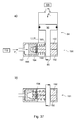
- a retaining means 191 shown in FIG. 37 is provided instead of the retaining means 111 fixing the stop 79, by means of which the transmission member 85, in particular the piston rod 85 or a corresponding extension piece, can be clamped.
- the holding means 191 may be integrated in the actuator 84, or as shown between actuator 84 and stop 79 may be arranged in such a way that the transmission member 85 is either fixable or freely movable in its direction of movement.
- the holding means 191 has, for example, two clamping jaws 192 with openings 193 or at least recesses for gripping around the transmission member 85, which are so operatively connected to the transmission member 85 that they release the transmission member 85 in a first operating state in which the longitudinal axis of the apertures 193 extend parallel to the transmission member 85, and in a second operating state in which the longitudinal axes the openings 193 tilted with respect to the longitudinal axis of the transmission member 85, in particular spread apart against each other, the last-mentioned with respect to a movement is clamped.
- the holding means 191 is self-locking, so that when not actuated holding means 191, z. B. by the force of a spring 194, the second operating state is taken.
- the holding means 191, in particular the actuator 196 can in principle be operated manually, for example via a corresponding actuating device, or advantageously by means of an actuator 197, in particular remotely operated, non-manually operable.
- the actuator 197 is formed in Fig. 37 as acted upon with pressure medium cylinder 197, in which the piston formed as an actuator 196 is movable.
- a return of the stop 79 can either by the spring 86 shown in FIG. 9 or - as shown in phantom in FIG. 37 - active by the formation of the actuator 84 as a pressure medium actuated cylinder with double-acting piston, so with two pressure medium supply, one each on both sides of a piston 90.
- all four cylinders 06; 07 by actuators 82 on / ab contemplat stored, but only the stops 79 of the two forme cylinder 07 and one of the transfer cylinder 06 is not manually, ie on the pressure-actuated actuators 84, in particular remotely operated, are adjustable.
- the stop 79 of the other transfer cylinder 06 is, for example by means of a set as a screw adjustment means 84, adjustable and lockable. He must therefore, for example, have no holding means 111.
- one of the two transfer cylinders 06 although adjustable in its position, but not in the sense of an on / Abstellterrorism operatively movable but mounted frame-fixed.
- the three other cylinders 06; 07 are then movably mounted in the sense of an on / off, wherein in a first variant, all these three cylinders 06, 07 and in the second variant, only the different from the specified transfer cylinder 06 transfer cylinder 06 has a movable stop 79 and possibly the holding means 111.
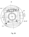
- the bearing units 14 of the forme cylinder 07 and / or the transfer cylinder 06 as shown schematically in Fig. 25, on at least one end face itself in bearings 113, z. B.
- linear bearings 113 movably mounted in a direction of movement C, which is perpendicular to the cylinder axis of rotation and at least one component perpendicular to the direction of adjustment S has.
- the direction of movement C is selected perpendicular to the direction of adjustment S and causes unilateral actuation an inclination (so-called. "Cooking") of the relevant cylinder 06; 07.
- the adjustment of the cylinder 06; 07 can via a manual or motorized actuating means 114, z. B.
- Such additional storage of the bearing unit (s) 14 on the forme cylinder 07 allows an inclination of the same and a passport adjustment, and allows the transfer cylinder 06 whose Inclination.
- the actuator 82 provided in the above embodiment of the bearing units 14 is designed to provide a travel ⁇ S suitable for engagement or deactivation, and therefore preferably has a stroke corresponding at least to ⁇ S.
- the actuator 82 is provided for adjusting the contact pressure of rollers or cylinders 06, 07 and / or for carrying out the pressure on / off adjustment, and designed accordingly.
- the travel ⁇ S (or stroke) is for example at least 1.5 mm, in particular at least 2 mm.
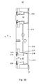
- Fig. 38 is an advantageous embodiment of a -.
- This Aktorelement 97 comprises at least one, preferably two actuated with pressure medium as a piston 82 formed actuators 82 which in recesses 213 of a base body 215, which serve as pressurizable means pressure chambers 213, movable in the direction of adjustment S. are stored.
- the actuator element 97 also includes a supply line 214 for supplying the pressure chambers 213 with pressure medium of the pressure P.
- the two pressure chambers 213 are supplied by a common supply line and thus oppressed or relieved in the same way.
- the upper piston 82 is exemplified for both pistons 82 in a retracted and the lower piston 82 exemplified for both pistons 82 in an extended position.
- the supply line 214 was also only partially characterized as being pressurized.
- the piston 82 is sealed against the pressure medium chamber 213 by a seal 82 surrounding the circumference of the piston 82, near the pressure chamber, and a sliding guide 217 close to the pressure chamber is guided.
- a second seal 218 and a second slide guide 219 may additionally be provided in a region of the piston 82 remote from the pressure chamber.
- a membrane 220 for. B. rubber, in particular a rolling diaphragm 220 sealed. This is on the one hand completely with the piston 82 and on the other hand on its outer peripheral line completely connected to the base body 215 and other fixed internals of the actuator element 97.
- the printing unit 01 are both parts of the printing unit 01, in particular wall sections 11; 12; 49 for the purpose of equipping or servicing the printing unit 01 relative to each other, in particular in a linear guide 15, as well as cylinder 06; 07 for adjusting the setting pressure and / or for performing the pressure on / off in linear bearings 70 within the corresponding wall section 11; 12 arranged linearly movable.
- a pressure cylinder gear with its own drive motor here includes, for example, the drive of a form cylinder-transfer cylinder pair.
- Farbwerksgetriebe with its own drive motor (for rotation and traversing movement) and, in the case of wet offset, a dampening with its own drive motor (for rotation and traversing movement) a high level of o. Modularity.
- the preferably prefabricated as modules gear units can be used as subunits for the printing cylinder 06; 07 (FIGS. 26, 27) and / or for the inking units 08 (FIGS. 26, 27), which are embodied, for example, as a module, and in an advantageous embodiment already before being inserted into the printing unit 01 on the frame 147 (or frame construction 16). be pre-assembled the inking module.
- the modularity also allows the installation / replacement / replacement of the module designed as a transmission when the inking unit module is already inserted into the machine.
- the concept of modularity for separate Druckwerkszylinder-, Farbwerks- and dampening unit drive allows both the divisibility of printing unit 01 at the pressure point 05 (see, for example, Fig. 3) and the divisibility between form cylinder 07 and inking unit 08 (see Fig. 24).
- the separate modules for printing cylinder 06; 07, inking unit 08 and possibly dampening unit 09 also allows simultaneous setup operation such as printing plate change and / or blanket washing while a Farbwerk consequent and / or pre-inking takes place.
- the sequence programs can be different from one another in terms of duration, speed and functional sequence.
- the transmission or the gear train of the respective drive modules is designed in a preferred embodiment in each case as a single-encapsulated transmission and driven by at least one of the other functional modules mechanically independent drive motor.
- the conditions for the dry offset are shown on the left side of the figures, and for the wet offset on the right side.
- the two printing units 04 of a real double printing unit 03 was omitted for reasons of clarity on the roll pattern and only the drive trains are shown with motors.
- the drive concept is exemplified by the example of an inking unit 08 with two rotationally driven friction cylinders 33 (see inking unit 08.2) and - in the case of wet offset - in contrast to Figures 11a) and 11b) - a dampening unit 09 with two rotationally driven friction cylinders 33 (shown in Fig. 26 by barlining as optional).
- the drive of the printing cylinder 06; 07 takes place at least in pairs, d. H. it is per cylinder pair 06, 07 from form and associated transfer cylinder 07; 06 at least one of further printing unit cylinders mechanically independent own drive motor 121 is provided.
- This can be z. B. in a variant, not shown, each be a separate, mechanically independent drive motor 121, or as shown below, done by paired drive via drive connections or trains.
- Fig. 26a is in front view and in Fig. 26b) is a plan view of a gear or drive train 122, in particular as a drive or function module 122 executed, respectively for the pressure cylinder pairs 06, 07 shown.
- the cylinders 06; 07 each rotationally fixed on the drive shafts 78 connected drive wheels 123, in particular spur gears 123, whose head diameter is smaller than the outer diameter of the respective cylinder 06; 07 or bales 67; 68.
- These spur gears 123 are connected to each other via an even number of intermediate wheels 124; 126, here two, gears 124; 126 in drive connection.
- intermediate wheels 124; 126 here two, gears 124; 126 in drive connection.
- one of the two gears 124; 126 in particular the Nicolszylindernahe gear 126, effective as a pinion and driven by the motor shaft 127 of the drive motor 121.
- the drive from the drive motor 121 can also take place via an additional pinion on one of the two drive wheels 123, in particular on that of the transfer cylinder 06.
- the inking unit 08 each has its own, from the printing cylinder 06; 07 mechanically independent drive motor 128 for the rotary drive on.
- the two distribution cylinders 33 of the inking unit 08.2 (in the case of an anilox roller 26, this or three friction cylinders 33 these three), z. B. driven by these rotatably connected drive wheels 129 and a drive pinion 131.
- wet offset (right) essentially the same applies to the drive of the dampening unit 09 with a drive motor 132, a drive pinion 133 and one or more drive wheels 134 shown in broken lines one or more distribution cylinders 42; 48.
- 26b is per distribution cylinder 33 of the inking unit 08 and each distribution cylinder 42; 48 of the dampening 09 a the axial traverse movement generating friction gear 136 and 137 arranged.
- This can in principle be driven by an additional drive motor, or as shown as a rotational movement in an axial movement transforming gear 136; 137 be formed.
- the drive of the inking unit 08 can be carried out according to FIG. 32, d. H. only the form cylinder remote friction cylinder 33.2 rotatory, but possibly both distribution cylinder 33.1; 33.2 axially forcibly driven, and / or the drive of a three-roll dampening unit 09 as mentioned above for the development of Fig. 11a) to be rotationally driven purely by friction.
- these drive modules 138; 139 as a complete unit mountable and preferably carried out for each encapsulated (see Fig. 26b).
- Fig. 26 is an example of the other drive variants of the following figures, an advantageous embodiment of the bearing as bearing units 14 in the above-mentioned embodiment for the storage of the four cylinders 06; 07 indicated.
- the waves 78 are, for example, by corresponding recesses / openings - possibly with regard to the modularity and therefore different center distances as a slot - in the side frame 11; 12 led.
- the axes of rotation of the four printing group cylinders 06; 07 of the double printing unit 03 arranged by way of example in the common plane E.
- the drive concept of Fig. 26 or 27 is also on non-linear arrangements of the cylinder 06; 07 as exemplified in Fig. 1, 28 and 29 with then corresponding non-linear arrangement of the drive wheels 123 to transmit.
- the printing group cylinders 06; 07 and the inking units 08 own drive as shown in Fig. 26.
- color and dampening drive are each designed as separate function modules, but the wet offset representing right printing unit 04 a dampening 09 without its own rotary drive motor.
- the rotary drive takes place here from the inking unit 08 forth via a mechanical drive connection 141, z. B. a belt drive 141, either directly on a with the respective distribution cylinder 42; 48 connected drive wheel, z.
- the drive is z.
- the drive of the inking unit 08 can take place in accordance with FIG. 32, ie, only the friction cylinder 33.2, which is remote from the mold cylinder, rotationally, and possibly both, the friction cylinder 33.1; 33.2 driven axially forcibly, and driven from there to the dampening unit 09.
- the dampening unit 09 is designed as a functional module and, as in FIG. 26, has its own drive motor 132 as in FIG. 26.
- the inking unit 08 has none of the printing cylinders 06; 07 independent drive motor, but the rotary drive is carried by one of the cylinder 06; 07, in particular from the forme cylinder 07, forth via a mechanical drive connection 144, z. B. via at least one intermediate gear 144, in particular gear 144, between the spur gear 123 and drive wheel 129 of the distribution cylinder 33.
- the drive connection 144 may be performed in an advantageous variant as a belt drive.
- the drive of the printing couple cylinder pair 06, 07 with associated inking unit 08 is preferably as a drive train 146 or drive or function module 146, in particular at least the drive train of cylinder pair 06, 07 and inking unit 08 having space is z. B. formed encapsulated.
- the drive of the inking unit 08 can take place in accordance with the principle set out in FIG. 32, ie. H. it is only the form cylinder remote friction cylinder 33.2 rotationally via a drive connection from the forme cylinder 07 ago, but possibly both distribution cylinder 33.1; 33.2 axially forcibly driven.
- the drive of a three-roll dampening unit 09 can be driven rotationally via the drive motor 132 or, as mentioned above for the development of FIG. 11 a), purely via friction.
- the dampening unit 09 is designed as a functional module and, however, as in FIG. 27, does not have its own drive motor.
- the inking unit 08 has, as in FIG. 28, an independent drive motor but, as in FIG. 28, rotates again by one of the cylinders 06; 07, in particular from the forme cylinder 07, forth via a drive connection 144, z. B. an intermediate gear 144 is driven.
- the drive of the dampening unit 09 is effected as in FIG. 27 via a belt drive 141.
- the drive of the printing couple cylinder pair with associated inking unit 08 is preferably again embodied as a function module 146, in particular encapsulated. In a modification to Fig.
- not shown fifth variants can be executed together as a functional module with a common drive motor in wet offset pressure cylinder gear and dampening gearbox, the function module 138 z. B. itself as shown in FIG. 26 is maintained and has a drive motor 128.
- the inking unit 08 is designed as a functional module 138, it is driven without a separate motor via a belt drive from the impression cylinder gearbox.
- the drive modules 122 with the two printing unit cylinders 06; 07 in each case via at least one torsionally rigid coupling 148, in particular at least one angle-compensating coupling 148 coupled.
- two such couplings 148 are provided in series with an intermediate piece (or a total of a double-jointed component) which then represents a total of an offset compensating coupling 151. This is despite mobility (on / off) of the cylinder 06; 07 a frame-fixed arrangement of the drive modules 122 and drive motors 121 possible.
- the coupling (s) 148 having shafts 78 must be flanged to the self-completed function modules 122.
- the clutch 148 is designed in each case as a multi-disc clutch 148 or all-metal clutch and has at least one form-locking, but offset in the circumferential direction of the blades offset with two flanges disc set.
- the coupling 151 between the functional module 122 and the forme cylinder 07 is preferably designed to enable side register control in such a way that it also receives an axial relative movement between the forme cylinder 07 and the functional module 122. This can also be done by o.g. Multi-plate clutch 148 take place, which allows an axial length change by deformation in the region of the slats.
- An unillustrated axial drive can be provided on the same or the other frame side as the rotary drive.
- the driven rollers 33, in particular friction cylinder 33, of the inking unit 09 are preferably coupled to the functional module 138 via at least one coupling 149, in particular angle compensating compensating coupling 149. Since i.d.R. no Ab / employing these rollers 133 takes place, it may be left in such a clutch 149.
- the coupling 149 is also designed only as a rigid flange connection. The same applies to the drive on possibly as a function module 139.
- the friction gear 136; 137 outside of an encapsulated the rotary drive trains accommodating space, in particular lubricant space, be arranged.
- the drive modules 122; 138; 139; 146 running drive trains 122; 138; 139; 146 are completely separate by themselves from side frames 11; 12 different - housing 152; 153; 154 completed units executed. They have For example, an input to which z. B. a drive motor or a drive shaft can be coupled, and one or more outputs which rotatably with the cylinder 06; 07 or the roller (screen or friction roller 26, 33, 42, 48) is connectable.
- the pressure cylinder 06; 07 in a likewise advantageous embodiment also each individually by a drive motor 121 to be driven (Fig. 30).
- a transmission 150 in particular a reduction gear 150, such. B. a planetary gear provided.
- This can be structurally already pre-assembled as an auxiliary unit with the motor 121 as a structural unit as an auxiliary transmission.
- it can also be provided as a drive or functional module, a module-like transmission, at the input of the drive motor and at the output of the respective cylinder - in particular via an angle and / or offset compensating coupling 148 or 151 - can be coupled.
- the drive motors 121 with their drive modules 122 or transmissions 150 are arranged fixed to the frame on the side frames 12.
- the necessary offset when turning on / off the nip points is made possible by the clutches 148 here.
- To support the drive motors 121 may be provided on the side frame 12, a holder with guide on which the drive motor 121 are supported and upon movement of the respective cylinder 06; 07 in the direction S can be moved.
- Fig. 31 to 35 shows a -. B. respect. Color transport and wear advantageous - embodiment of the inking unit 08 and the inking unit drive, which by itself, However, especially in conjunction with one or more features of the above printing units 01 advantages.
- the inking 08, z. B. referred to as hereinaboges roller inking unit 08 or as a "long inking unit”, has a plurality of the above-mentioned rollers 28; 33; 34; 36; 37 on. According to FIG. 31, it comprises (at least) two application rollers 28, which apply the ink to the printing forme of the forme cylinder 07 and which transfer the ink via a printing forme cylinder or form cylinder near oscillating friction roller 33.1 or friction cylinder 33.2 (eg with a hard surface).
- a color or transfer roller 34 eg, with a soft surface
- a second changeable friction roller 33.2 or friction cylinder 33.2 remote from the mold cylinder e.g., a further color or transfer roller 34 (eg, with a soft surface)
- a film roller 37, and a Ductor or fountain roller 36 from a color box 38 receives.
- Dipping and film roller 36; 37 characterizing a film inking unit
- can advantageously also be replaced by another ink feed or metering system eg pumping system in the pumping inking unit, or lifting system in the lifting inking unit).
- the soft surfaces of the application and / or transfer rollers 28; 34 are yielding in the radial direction, z. Formed with a rubber layer, which is expressed in Fig. 31 by the concentric circles.
- a rotary positive drive was performed by specifying a speed (eg via a Drive motor or a corresponding mechanical drive connection to another driven component), then rotates an adjacent, driven only by friction of the former roller ago soft roller depending on Eindguriefe with different speeds.
- this soft roller but in addition by its own drive motor or additionally via friction in a second nip point would be driven by another speed-specific roller ago, this can be caused in the first case to a difference between motorized speed and by friction Speed, and in the second case to come to a difference between the two speeds caused by friction. Slippage occurs at the nip points and / or the drive motor (s) are unnecessarily heavily loaded.
- the form cylinder near the friction cylinder 33.1 is rotational only by friction with adjacent rollers 28; 34 driven and has its rotary drive neither an additional mechanical drive connection for driving the printing cylinder 06; 07 or another rotary forcibly driven inking roller nor its own drive motor.
- the first distribution cylinder 33.1 is rotationally driven predominantly via the application rollers driven by friction with the forme cylinder 07 in this example (optionally also one or three) and essentially has the peripheral speed of the application independently of the indentations in the intermediate nip points Form cylinder 07 on.
- the form cylinder remote friction cylinder 33.2 has, as indicated in Fig.
- a rotationally driving drive motor 128, which, however, in addition to the through the rollers 33.2; 34; 33.1 formed friction gear has no mechanical coupling to the first distribution cylinder 33.1.
- the cylinder near cylinder near friction cylinder 33.1 has its own, only its rotational movement in a traversing motion transforming traversing 136.
- This can be advantageously designed as a cam gear, wherein z. B. a frame-fixed axial stop cooperates with a roller-fixed curved circumferential groove or a roller-fixed axial stop in a frame-fixed circumferential groove of a cam.
- this rotation in a iridescent Axialhub transforming gear 136 another suitable gear 136, z. B. by an eccentric exhibiting worm or crank gear, be executed.
- the traversing gear 136 of the first rubbing cylinder 33. 1 is mechanically coupled in an advantageous manner via a gear 161 to the traversing gear 136 of the second rubbing cylinder 33.
- the two coupled traversing gears 136 represent a common traversing drive 162 (traversing gear 162) and are forcibly driven for their traversing movement by a drive motor.
- the forced drive of the traversing gear 162 is effected by the drive motor 128 rotationally driving the second distribution cylinder 33.2 (FIG. 32).
- Fig. 32 and 33 is an advantageous embodiment for the drive of the distribution cylinder 33.1; 33.2, wherein only the second distribution cylinder 33.2 is forcibly driven in rotation, but both distribution cylinders 33.1, 33.2 are axially positively driven via the common traversing drive 162.
- the printing cylinder 06; 07 can either be as shown in Fig. 26 in pairs by drive motors 121 per cylinder pair, or advantageously individually by a respective drive motor 121 as shown in Fig. 30, executed.
- the drive motor 128 drives via a coupling 163 via a shaft 164 to a drive pinion 166, which in turn interacts with a spur gear 167 connected non-rotatably to the second distribution cylinder 33.2.
- the connection can z. B. via a spur gear 167 supporting shaft portion 168 carried on a pin 169 of the second Reibzylinders 33.2.
- a corresponding axle section 168 of the first friction cylinder 33.1 has no such spur gear 167 or no drive connection to the drive motor 128.
- the drive connection between the drive pinion 166 and spur gear 167 of the second Reibzylinders 33.2 are preferably straight teeth and formed with a sufficient for each position of traversing movement coverage in the teeth engagement.
- the two distribution cylinders 33.1; 33.2 are in a formed on the side frame 147 or frame 16 frame 147 in bearings 172, z. B. radial bearings 172 stored, which also allow axial movement.
- a rotary drive connection between the drive motor 128 and the first distribution cylinder 33.1 does not exist here.
- Drive pinion 166 and disposed on the axle 168 spur gear 167 together represent a transmission, in particular reduction gear, which is a self-contained and / or preassembled unit with its own housing 153. The assembly is the output side of the pin 169 coupled.
- the traversing drive 162 is also by the drive motor 128, z. B. via a worm drive 173, 174, driven.
- a screw 173 arranged from the shaft 164 or a section of the shaft 164 designed as a screw 173 is rubbed onto a worm wheel 174, which is rotationally fixed with a rotation axis of the friction cylinder 33.1 perpendicular to the axis of rotation. 33.2 extending shaft 176 is connected.
- a driver 177 is arranged eccentrically to the axis of rotation, which in turn z. B.
- a crank mechanism for example via a rotatably mounted on the driver 177 lever 178 and a hinge 179, in the axial direction of the distribution cylinder 33.1; 33.2 pressure and zugsteif with the pin 169 of the distribution cylinder 33.1; 33.2 is connected.
- the friction gear 136 of the form cylinder distant friction cylinder 33.2 is only indicated by dashed lines, since it is hidden in this view by the spur gear 167.
- a rotation of the shaft 176 causes a rotation of the driver 177, which in turn via the crank drive an axial stroke of the distribution cylinder 33.1; 33.2 causes.
- the output to the traverse drive 162 can also take place at another point of the rotary drive train between the drive motor 128 and the friction cylinder 33.2 or even on the other side of the machine on the other end face of the Reibzylinders 33.2 pin 169 to a corresponding traversing gear 162. Also may optionally be provided by a worm gear 173, 174 different gear for coupling the axial drive.
- the traversing drive 162 or the traversing gear 162 as a whole is designed as a structural unit with its own housing 181, which may be additionally encapsulated.
- the traversing gear 162 may be lubricated in the enclosed space either with oil, but preferably with a grease.
- the traverse gear 162 is supported in the illustrated embodiment by a bracket 182 connected to the side frame 147.
- the drive motor 128 is in this case detachably connected to the housing 181 of the traversing gear 162.
- Fig. 34 shows an advantageous embodiment of a torsionally rigid connection between the axle portion 168 and the respective pin 169. This is about a rotation about a frictional engagement, which is made by clamping a tapered portion of the pin 169 by the slotted axle portion 168 comprising this becomes.
- the position of a clamping screw 183 is dimensioned such that it - at least partially immersed in a circumferential groove of the pin 169 - viewed transversely to the axis of rotation of the pin 169. It thus represents an interlocking securing of the connection with respect to an axial direction.
- FIG. 35 wherein the distribution cylinders 33. 1; 33.2 including rotary and axial drive in the manner of a total pre-assembled and / or movable module on its own, of a the printing cylinder 06; 07 carrying side frames 11; 12 structurally different side frames 147 (16) are arranged.
- the friction cylinder 33.1; 33.2 on its other end side supporting frame side is not shown here.
- These the friction cylinder 33.1; 33.2 and their drive supporting side frames 147 (16) are then depending on the size and geometric arrangement of the printing cylinder 06; 07 on the side frame 11; 12 positionable. Figs.
- 35a) and 35b) show a relative position of the side frames 147 (16) and 11; 12 to each other when using a larger (a) and a smaller (b) forme cylinder 07.
- a marked by double arrow in Figure 35 distance between the side frame 11; 12 and the inking unit drive, here the traversing gear 162, is then different depending on the position of running in the manner of a module inking unit 08.
- This can print units 01 with printing cylinders 06; 07 different circumferential formats can be operated in a simple manner by the same inking unit 08.
- the prefabricated preferably as a module transmission unit may be completely pre-assembled as a subunit for example designed as a module inking 08 and pre-assembled in an advantageous embodiment before use in the printing unit 01 on the side frame 147 (16) of the inking module be.
- the modularity also allows the installation / replacement / replacement of the module designed as a transmission when the inking unit module is already inserted into the machine.
- the drive motor 128 which rotatably drives the second distribution cylinder 33.2 can be embodied as an electric motor that is controllable with respect to its power and / or its torque and / or also with respect to its speed. In the latter case, if the drive motor 128 is also operated in speed-controlled / pressure-controlled manner, then in the region of the inking unit 08 remote from the printing cylinder, it may still be too o. G. Problems arise with regard to different effective roll circumferences.
- the drive motor 128 is advantageously designed such that it at least during the printing operation with respect. Its power and / or its torque is controlled or regulated. This can basically be done by means of a drive motor 128 designed as a synchronous motor 128 or as an asynchronous motor 128:
- the drive motor 128 is designed as an asynchronous motor 128, which has only one frequency (eg in pressure-down of the inking unit 08) in an associated drive control 186 and / or an electric drive power or a torque (in print-on of the inking unit 08) is specified.
- the inking unit 08 can be brought about the second distribution cylinder 33.2 to a suitable peripheral speed for the pressure on-jobs on the predetermined frequency and / or drive power in which the peripheral speeds of forme cylinder 07 and applicator rollers 28 only differ by less than 10%, in particular less than 5%, from one another (this limit advantageously also applies as a condition for the pressure on the embodiments mentioned below).
- a suitable frequency or power specification is empirically and / or computationally determined in advance and either in the drive control itself, a machine control or a control center computer maintained.
- the default value is preferably changeable by the operator, wherein the default value is preferably changeable by the operating personnel (advantageously also applies to the default values mentioned below).
- the applicator rollers 28 are placed in rolling contact with the forme cylinder 07 and all inking rollers to each other, the rollers 28; 33; 34; 33; 34; 37 to a part of the forme cylinder 07 via the now produced friction gear between the rollers 28; 33; 34; 33; 34; 37 rotationally driven. so that the drive motor 128 only has to bring in the increasing power dissipation in the friction gears with increasing distance from the forme cylinder 07. That is, the drive motor 128 can be operated with a small drive torque or a small drive power, which only contributes to keep the rear portion of the inking unit 08 at the substantially predetermined by the frictional contact peripheral speed.
- This drive power can be left constant in a first variant for all production speeds (or rotational speeds of the forme cylinder 07) and either correspond to that specification for starting in pressure-Ab or represent its own constant value for the production.
- different specifications with regard to the frequency and / or drive power can be predetermined and stored for different production speeds (and possibly also for starting in pressure-off).
- the specification for the drive motor 128 can then vary.
- the drive in addition to the drive control 186 and the induction motor 128 of the first embodiment, a speed feedback, so that the drive motor 128 in the phase of the inking unit operation in pressure-Ab with the speed of the associated plate cylinder 07 and the printing cylinder 06; 07 is essentially synchronizable.
- the actual speed detecting sensor 187, z As a rotary encoder 187, on a non-rotatably connected to the distribution cylinder 33.2 rotating component, eg. B. a rotor of the drive motor 128, the shaft 164, the shaft 164, etc. may be arranged.
- a rotary encoder 187 on a non-rotatably connected to the distribution cylinder 33.2 rotating component, eg. B. a rotor of the drive motor 128, the shaft 164, the shaft 164, etc. may be arranged. In FIG.
- a rotary encoder 187 having a co-rotating initiator and stationary sensor 187 is shown by way of example on the coupling 163, the signal of which is fed to the drive control 186 for further processing via a signal connection shown in dashed lines. Due to the speed feedback, the comparison with a rotational speed M representing the engine speed and a corresponding adjustment of the power or frequency specification, a slip at the moment of pressure on-position can be avoided or at least minimized to a few percent. In the print-on operation, the drive motor 128 is then preferably no longer strictly with respect to the described speed feedback but essentially operated according to the frequency or power specification described above.
- a third embodiment has a synchronous motor 128 instead of the asynchronous motor 128 of the second embodiment.
- a speed feedback and a related synchronization and control in the pressure-off phase is carried out according to the second embodiment, for. B. again in the drive control 186th
- a drive motor 128, in particular a synchronous motor 128, is provided, which is optionally speed-controlled in a first mode (for inking unit 08 in print-Ab) and in a second mode with respect to a torque (for inking unit 08 in print-on). is controllable.
- Drive control 186 and drive motor 128 preferably have an internal control loop for speed control, which, similarly to the second embodiment, comprises a return from an external rotary encoder 187 or an internal sensor system.
- synchronous motors 128 are used, a plurality of these synchronous motors 128 of a printing unit 01 can be assigned a common frequency converter or converter.
- a respect to versatility advantageous, but more complex development of the fourth embodiment is the formation of the drive motor 18 as optional position and torque-controllable servomotor 128, ie, a three-phase synchronous motor having means for allowing the current rotational position to be determined with respect to an initial position of the rotor.
- the feedback of the rotational position can via a rotary encoder, z.
- each drive motor 128 is assigned its own frequency converter or converter.
- the drive control 186 is advantageously in signal connection with a so-called virtual master shaft in which an electronically generated master axis position ⁇ circulates.
- the circumferential Leitachsposition ⁇ is the synchronization, with respect to correct angular position and its temporal change (angular velocity ⁇ ) mechanically independent drive motors of aggregates, which are assigned to a same path, in particular drive motors 121 of individual printing cylinders 06; 07 or groups of printing cylinders (pairs) and / or the drive of a folder.
- a signal connection to the virtual master axis can thus provide the drive control 186 with the information about the speed or speed of the machine.
- the inking mechanism 08 is in operation, but is controlled and regulated in terms of a rotational speed and is driven when the inking unit 08 is running (but in parked applicator rollers 28) running machine, as soon as a pressure on the inking unit 08 (ie the applicator rollers 28) is done, the speed control or control is deliberately abandoned.
- D. h. It is no longer held at a speed, but the drive motor 128 is in the course of a torque, z. B. over a predetermined electrical power, and / or with respect to a on the controller of a drive motor 128, in particular asynchronous motor 128, adjustable torque operated.
- the torque to be set or the power to be set for example, is selected to be smaller than a limit torque which would lead to a first rotation (under slip) of the driven friction cylinder 33.2 when the cooperating rollers 34 are set but fixed with respect to rotation.
- the load characteristic of a drive motor 128 embodied as an asynchronous motor 128 counteracts the behavior intended for the purpose here in such a way that, as the load increases, the frequency is reduced while the drive torque increases. Goes in the friction gear between forme cylinder 07 and second friction cylinder 33.2, for example, already a lot of form cylinder 07 derived drive energy and thus peripheral speed lost, so that the load of the drive motor 128 grows, so the increased torque is provided at a reduced frequency. Conversely, little torque is transmitted by the drive motor 128 - it runs virtually empty - when sufficient energy is transmitted through the friction gear to the distribution cylinder 33.2.
- the design of the cylinder bearings as bearing units 14 and / or the cylinder 06; 07 as a cylinder unit 17 and / or the inking units 08 in the form of modules and / or drives in the manner of drive modules and / or the separability of the printing unit 01 allows - depending on equipment at different depths - a simplified on-site assembly and thus extremely short installation - and commissioning times at the customer.
- the side frames 11; 12 or wall sections 11; 12; 47 set up and aligned and the cylinder units 17 and / or inking units 08 and / or dampening 09 in the manner of modules outside the side frames 11; 12 pre-assembled.
- the cylinders 06; 07 are still outside of the racks 11; 12 equipped with their storage units 14 and then completely as a cylinder units 17 between the side frames 11; 12 introduced and fixed. From the outside of the side frame 11; 12 is then by corresponding frame recesses - depending on the drive version - the drive unit in the manner of a drive module (eg, gear 150 or drive train 122 with the corresponding drive motor 121, if necessary, via the shaft 78) with the pin 63; 64 connected.
- a drive module eg, gear 150 or drive train 122 with the corresponding drive motor 121, if necessary, via the shaft 78
- the cylinder units 17 are preferably opened when the printing unit 01 is open, from between the two partial printing units 01.1; 01.2 lying room introduced and only after introduction this again closed.
- the cylinder units 17 are preferably at between printing cylinders 06; 07 and the inking units 08 receiving wall sections 47 open pressure unit 01 introduced from the space formed therefrom ago and closed only after introduction of these.
- the own inking frames 16 and 147 are still outside the side frames 11; 12 equipped with the corresponding rollers (from 26 to 39) and the corresponding drive module 138 (possibly already including drive motor 128) and introduced as a whole in the printing unit 01 and fixed there.
- dampening 09 can dampened own racks still outside the side frames 11; 12 with the corresponding rollers (from 41, 42, 43, 47, 48) and, if required in the desired embodiment, the corresponding drive module 138 (optionally with or without its own drive motor 132) and introduced as a whole into the printing unit 01 and be fixed there.
- FIGS. 39 a) to 39 d) schematically show four embodiments for a printing machine, which has a plurality of printing units 01 described above-divisible or possibly not divisible.
- the printing presses have reelstands 236 with retractors (237) not explicitly shown, a superstructure 238 with at least one longitudinal cutting device, a reversing corner and a longitudinal register device for longitudinally cut partial webs, optionally a dryer 239 (dashed line) exemplarily shown in FIG. 39d), a funnel structure 241 with depending on the web width one, two or even three juxtaposed in a plane folding hoppers and a folder 242.
- this three printing units 01 having printing machine are in the case of a design with double-wide, d. H. four printed pages (especially newspaper pages) wide and double-sized printing cylinders 06; 07 with three tracks 02 altogether 48 pages each four-color printable.
- Fig. 39 a shows the printing machine in Patterre line-up, d. H. the printing units 01 and the roll changer 236 are set on a same level.
- Fig. 39b a printing machine is shown, wherein two each four double printing units 03 having printing units 01 are arranged on two different levels.
- the upper printing unit 01 is arranged with its entire height above the lower printing unit 01.
- this three printing units 01 having printing machine are in the case of a design with double-wide, d. H. four printed pages (especially newspaper pages) wide and double-sized printing cylinders 06; 07 with three tracks 02 altogether 48 pages each four-color printable.
- Fig. 39 c shows a printing machine on three levels, wherein in a lowermost level, the roll changer 236, and on the two levels above two each four double printing units 03 having printing units 01 are arranged one above the other.
- the printing press has two such pairs of two printing units 01 arranged one above the other.
- this four printing units 01 having Printing machine are in the case of an embodiment with double-wide, ie four printed pages (especially newspaper pages) wide and double-sized printing cylinders 06; 07 with four lanes 02 a total of 64 pages each can be printed in four colors.
- a printing machine is shown on two levels, wherein in the lower level, the roll changer 236 and in the plane above the four double printing units 03 having printing units 01 are arranged.
- this three printing units 01 having printing machine are in the case of a design with double-wide, d. H. four printed pages (especially newspaper pages) wide and double-sized printing cylinders 06; 07 with three tracks 02 altogether 48 pages each four-color printable.
- a folder 242 is preferably provided with its own drive motor and / or with variable format or section length (i.e., a variable format folder 242) mechanically independently of the printing units 01.
- the folder 242 shown schematically in Fig. 40 has z.
- a knife cylinder 243 a transport cylinder 244 and a jaw cylinder 246.
- At least the transport cylinder 244 designed as a folding blade cylinder 244 has a variable-format configuration, ie a distance ⁇ U in the circumferential direction between holding means 247 and respectively subsequent folding blades 248 on the circumference of the transporting cylinder 244 is variable.
- the holding means 247, z. B. asillonurologyn or gripper executed, on the one hand and the folding blade 248 on the other hand on two be arranged different coaxial drums, which can be rotated in the circumferential direction to each other.
- a product section 249 transversely cut off from a strand 251 by the knife cylinder 243 is folded transversely on extension of the folding blade 248 to a shorter section length and vice versa.
- the strand 251 may consist of one or more longitudinally folded or unfolded webs 02 or partial webs.
- FIG. 41 shows an example of the drive of a printing press with a plurality of printing units 01, which are here by way of example two, in the form of printing towers 01, which each have a plurality of printing units 03, here double printing units 03.
- the printing units 03 of a printing tower 01 together with their drive controllers 221, briefly drives 221 and the drive motors 121; 128 a group 223, z.
- the slave drive controller 224 can also subgroups of printing units 01 or manage other divisions.
- own subordinate drive control 224 having units, for. B. one or more guide elements of a superstructure 238 and / or funnel structure 241 and / or one or more folders 242 connected.
- the signal line 226 is here advantageously designed as a first network 226 in ring topology, in particular as a Sercos ring, which receives the Leitachsposition ⁇ through a parent drive 227 connected to the network 226. This generates the circulating Leitachsposition ⁇ on the basis of specifications relating to a given production speed, which they from a computing and / or data processing unit 228, z.
- B. a section computer receives.
- the computing and / or data processing unit 228, receives the specification of the production speed from a control station 229 or control center computer 229 connected to it.
- the transmission of the offset values ⁇ i to the subordinate drive control means 224 is carried out,. B. either via corresponding signal lines from the second network 231st directly to the drive control 224 (not shown), or advantageously via a control system 232, which is associated with the respective group 18 or the own subordinate drive control 224 having unit.
- the control system 232 is connected to the second network 231 (or to the computing and data processing unit 227).
- the control system 232 controls and / or controls, for example, those of the drive motors 121; 128 different actuators and drives of the printing units 03 and folders 242, z. As ink supply, positioning movements of rollers and / or cylinders, dampening, positions, etc.
- the control system 232 has one or more (in particular programmable) control units 233 on.
- This control unit 233 is connected to the subordinate drive control 224 via a signal line 234. In the case of several control units 233, these are connected by the signal line 234, z. B. a bus system 234, also interconnected.
- the drives 221 thus receive the absolute and dynamic information for circulating a common control axis position ⁇ , and via a second signal path, in particular via at least one second network 231, the information required for register-correct processing, in particular offset values ⁇ i , for the register-oriented relative position of the mechanically independent drives 221 or units transmitted.
- FIG. 43 shows, in a schematic, simplified representation, a detail of a printing unit 301 with an inking unit 302 and a dampening unit 303, each with rolls 304 that can be controlled in their contact pressure; 306; 307; 308; 309; 311, wherein this printing unit 301 with its inking unit 302 and its dampening unit 303 can be arranged in one of the printing units 01 described in connection with FIGS. 1 to 15 or 39.
- the controllable in their contact force rollers 304; 306; 307; 308; 309; 311 are adjustable.
- each of these rollers 304; 306; 307; 308; 309; 311 is simultaneously on two of the rotational body 312 provided in this arrangement; 313; 314; 316; 317 set so that each of these rollers 304; 306; 307; 308; 309; 311 each on its lateral surface two nip points N11; N12; N21; N22; N31; N32; N41; N42; N51; N52; N61; N62, substantially axially of the respective roller 304; 306; 307; 308; 309; 311 extending roller strips N11; N12; N21; N22; N31; N32; N41; N42; N51; N52; N61; N62.
- Each in its contact force controllable roller 304; 306; 307; 308; 309; 311 presses N11 in its respective roller strip; N12; N21; N22; N31; N32; N41; N42; N51; N52; N61; N62 with an adjustable contact pressure against its adjacent rotating bodies 312; 313; 314; 316; 317th
- the roller 304 is z. B. formed as a dampening roller 304 and forms its first nip site N11 with a z. B. as a cylinder 312, in particular as a forme cylinder 312 formed rotary body 312 and its second nip-site N12 with a z. B. as a dampening driver 313 formed rotational body 313.
- the roller 306 is z. B. formed as an inking roller 306 and forms its first nip site N21 with the forme cylinder 312 and its second nip site N22 with a z. B. as a color transfer roller 316 formed rotary body 316.
- the roller 307 is also z. B.
- inking roller 307 formed as an inking roller 307 and forms its first nip site N31 with the forme cylinder 312 and its second nip site N32 with the ink transfer roller 316, wherein the forme cylinder 312 z. B. is stored in a described in connection with FIGS. 17 to 23 or 25 bearing unit 14.
- dampening unit 303 z. B. another controllable in their contact force roller 308, z. B. an intermediate roll 308, which forms its first nip point N41 with the dampening 313 and its second nip point N42 with another dampening roller 314.
- In the inking unit 302 are z. B. two more controllable in their contact force rollers 309 and 311, z. B.
- roller 309 is its first nip point N51 with the ink transfer roller 316 and its second nip point N52 with another inking roller 317 and the roller 311 their first nip point N61 with the ink transfer roller 316 and their Form second nip site N62 with the other inking unit roller 317.
- the printing unit 301 likewise shown only schematically in FIG. 44 and in a section by way of example with an inking unit 302 and a dampening unit 303, in each case with rolls 304 which can be controlled in their contact force; 306; 307; 308; 309; 311 differs from the printing unit 301 shown by way of example in FIG. 43 in the arrangement of the roller 311 in the inking unit 302, whereby the printing unit 301 shown here by way of example in FIG. 44 also has its inking unit 302 and its dampening unit 303 in one of them can be arranged with the Fig. 1 to 15 or 39 described printing units 01. In the printing unit 301 shown in Fig.
- the roller 311 with its first nip N61 is not in contact with the ink transfer roller 316, but the roller 311 is set against the roller 309 so that the roller 309 has its second nip N52 not with the other inking roller 317, but with the roller 311 trains.
- the nip sites N52; N61 thus denote the same roll strip N52 in this example; N61.
- the controllable rollers 304; 306; 307; 308; 309; 311 each have two nip sites N11 in the arrangements shown in Figs. 43 and 44; N12; N21; N22; N31; N32; N41; N42; N51; N52; N61; N62 up.
- controllable rollers 304; 306; 307; 308; 309; 311 may be provided, in which this roller 304; 306; 307; 308; 309; 311 with only one adjacent rotating bodies 312; 313; 314; 316; 317 is in contact contact and of its second adjacent bodies of rotation 312; 313; 314; 316; 317 is turned off.
- Another operating position of at least one of the controllable rollers 304; 306; 307; 308; 309; 311 may provide that this controllable roller 304; 306; 307; 308; 309; 311 of all its adjacent rotating bodies 312; 313; 314; 316; 317 is turned off, while the other controllable rollers 304; 306; 307; 308; 309; 311 of this printing unit 301 in each case at least with an adjacent rotary body 312; 313; 314; 316; 317 are in physical contact.
- the printing unit 301 can for at least one of the controllable rollers 304; 306; 307; 308; 309; 311 also only a single adjacent rotary body 312; 313; 314; 316; 317 be provided.
- the printing unit 301 is arranged in a printing press producing a printing press, the printing press-as described above-preferably z. B. is designed as a newspaper printing machine and z. B. has a plurality of printing units 301 each having at least one inking unit 302 and / or a dampening unit 303.
- the printing unit 301 operates z. B. in a planographic printing process, preferably in an offset printing process, wherein a printing cylinder 301 belonging to the transfer cylinder and cooperating with the transfer cylinder impression cylinder in Figs. 43 and 44 are not shown (for these components of the printing unit 301 is rather to Figs 15 or 39).
- the dampening unit 303 is omitted when the printing unit 301 is operated in a dry offset printing process.
- the lateral surface of z. B. as a forme cylinder 312 formed rotational body 312; 313; 314; 316; 317 is occupied by at least one printing plate (not shown).
- a plurality of printing plates are arranged in the axial direction of the forme cylinder 312, in particular four or six printing plates.
- In the circumferential direction of the forme cylinder 312 z. B. two printing plates arranged one behind the other, so that a total of up to eight or twelve printing plates on the outer surface of the same forme cylinder 312 are arranged.
- the printing unit 301 can in its inking unit 302 and its dampening unit 303 a total of significantly more, but also less controllable rollers 304; 306; 307; 308; 309; 311, as shown by way of example in FIGS. 43 and 44.
- roller 304; 306; 307; 308; 309; 311 or the rotating body 312; 313; 314; 316; 317 is possible because the roller 304; 306; 307; 308; 309; 311 or its adjacent body of revolution 312; 313; 314; 316; 317 or both have an elastically deformable lateral surface.
- the rollers 304; 306; 307; 308; 309; 311 a rubberized jacket surface.
- the width is in the range of a few millimeters and z. B. between 1 mm and 10 mm.
- the controllable in their contact force rollers 304; 306; 307; 308; 309; 311 and their adjacent rotary bodies 312; 313; 314; 316; 317 have a diameter of z. B. 100 mm to 340 mm and an axial length z. B. between 1,000 mm and 2,400 mm.
- the width of the roller strip N11; N12; N21; N22; N31; N32; N41; N42; N51; N52; N61; N62 corresponds to that of the respective controllable roller 304; 306; 307; 308; 309; 311 on its adjacent rotary body 312; 313; 314; 316; 317 in the respective roller strip N11; N12; N21; N22; N31; N32; N41; N42; N51; N52; N61; N62 applied contact pressure.
- Each in its contact force controllable roller 304; 306; 307; 308; 309; 311 is mounted in each case at least one of its ends 318, but preferably with its two ends 318 each in a support bearing 321 with a radially displaceable roller mount 339, ie in a so-called roller lock 321, each support bearing 321 or roller lock 321 at least one, preferably several the roller 304; 306; 307; 308; 309; 311 acting actuators 322, wherein the actuators 322 in turn preferably arranged in a support for the bearing 321 and roller lock 321 housing and each z. B. are pressurizable with a pressure medium.
- the actuators 322 are described below as actuators 322 which can be pressurized with a pressure medium, which corresponds to their preferred embodiment, the control of the support bearings 321 and / or their actuators 322 described below is independent of the medium used for the application of the contact pressure becomes.
- the actuators 322 z. B. also be formed as actuators 322, the respective contact force z. B. exercise due to a hydraulic, electrical, motor or piezoelectric effect.
- actuated actuators 322 cause the roller retainer 339 with respect to the support bearing 321 in an orthogonal to the axial direction of the controllable roller 304; 306; 307; 308; 309; 311 is moved eccentrically.
- the radial stroke can be done on a linear or nonlinear trajectory.
- a roller lock 321 is shown in its structural design by way of example.
- 45 shows the roller lock 321 in a direction to the axis 319 of the roller 304; 306; 307; 308; 309; 311 parallel longitudinal section.
- Fig. 46 shows the roller lock 321 of Fig. 45 in a perspective view with a partial longitudinal section in two mutually orthogonal planes.
- At least all directly interacting with a forme cylinder 312 rollers 304; 306; 307 each have at least one actuator 322, which is independent of the other actuators 322 of the forme cylinder 312 directly cooperating rollers 304; 306; 307 is controlled. It is preferably provided that at least three rollers 304, which cooperate directly with the forme cylinder 312, are provided. 306; 307 are arranged and that each of these rollers 304; 306; 307 has at least one independently controlled actuator 322.
- the housing of the roller lock 321 has a z. B. sleeve-shaped frame holder 323, in the interior of a roller holder 324 is mounted, the actuators 322 act on the roller holder 324 in their operation and the roller holder 324 in a radially formed about the axis 319 gap between the frame holder 323 and the roller holder 324 radially can move.
- the gap between the frame holder 323 and the roll holder 324 has z. B. a width of 1 mm to 10 mm, preferably of about 2 mm.
- the actuators 322 are z. B.
- actuator 322 has a directed onto the roller holder 324 effective surface 338, with which the actuator 322 exerts a surface pressure on the roller holder 324 in its operating state acted upon by a pressure medium.
- the actuators 322 are preferably rotatably arranged in the housing of the roller lock 321 relative to this housing or at least relative to the frame holder 323.
- the actuators 322 are z. B. each as a pressurizable with a pressure medium hollow body, for. B. as a pressure hose, wherein the hollow body has at least one surface 338 (Fig. 46) made of a reversibly deformable elastomeric material, said surface 338 z. B. is formed in a further embodiment, not shown, as a membrane, wherein the membrane 338 preferably comes on the pressure medium loading of the hollow body on an outer circumferential surface of the roll holder 324 for support.
- the reversibly deformable surface 338 therefore at least largely corresponds to the surface 338 which is effective for applying the surface pressure.
- the actuators 322 have no piston guided in a cylinder, but instead are rodless.
- the integration of the actuators 322 into the housing of the roller lock 321 leads to an extremely compact construction of the roller lock 321.
- the pressure medium is supplied to the actuators 322 in each case via a pressure medium line 341 (FIG. 46).
- One of the ends 318 of the roller 304 which can be controlled in its contact force; 306; 307; 308; 309; 311 is formed in the formed on the roll holder 324 z.
- the roller mount 339 has a bearing, for. B.
- the frame holder 323 is z. B. attached to a frame wall 336 of the printing unit 301.
- the roller lock 321 is at its controllable in its contact force roller 304; 306; 307; 308; 309; 311 facing end face preferably with a particular gap between the frame holder 323 and the Roll holder 324 covering sealing element 337 sealed against dust, moisture and other contaminants, wherein the sealing element 337 z. B. is screwed to the frame holder 323.
- the sealing element 337 and in particular the actuators 322 are protected from contamination and thus from a disturbance in their mobility.
- the roller lock 321 has z. B. a fixing device, the roller holder 324 and thus the rigidly connected to him roller 304; 306; 307; 308; 309; Fixed 311 in a first operating position and thus locks against any radial displacement relative to the frame holder 323 or releases in a second operating position for such a shift.
- the fixing device has z. B. a preferably coaxial, rigid z. B. connected to the roller holder 324 first plate set 326 and also preferably coaxial second plate pack 327, wherein the second plate set 327 engages with its fins between the slats of the first plate set 326.
- the fixation takes place when meshing the slats preferably frictionally or positively. After loosening the zip or positive locking of the slats, the second disk set 327 in the axial direction of the roller lock 321 is movable.
- the axial movement of the second disk set 327 comes z. B. in that a pressure medium is guided by a formed in the frame wall 336 channel 328 in a roller lock 321 pressure chamber 329, wherein arranged in the pressure chamber 329 pressure plate 331 against the force of a spring element 332 a preferably arranged in the roll holder 324 Stamp 333 moved axially.
- the second disk set 327 is attached to a punch head 334 of the punch 333 and is also moved in an axial movement of the punch 333, whereby the fins of the disk sets 326; 327 disengaged.
- each roller lock 321 is four circular about the axis 319 of the roller 304; 306; 307; 308; 309; 311 arranged actuators 322, wherein the actuators 322 preferably at uniform intervals about the axis 319 of the controllable in its contact force roller 304; 306; 307; 308; 309; 311 are distributed.
- the actuators 322 can be remotely controlled, ie actuated by a control unit, and preferably designed as pneumatic actuators 322.
- As a prestressed gas preferably compressed air used.
- each actuator 322 exerts an actuation in the pressure medium Inside of its roller lock 321 directed radial force Fn1; Fn2; Fn3; Fn4 on the connected to the roller lock 321, controllable in its pressing force roller 304; 306; 307; 308; 309; 311, wherein the actuators 322 are preferably radially supported on or in the frame holder 323 of the roller lock 321 and by the surface pressure on the frame holder 323 radially displaceable roller holder 324, the radial force Fn1; Fn2; Fn3; Fn4 mounted on the roller holder 324, controllable in its contact force roller 304; 306; 307; 308; 309; 311 exercise.
- the one in their contact pressure controllable roller 304; 306; 307; 308; 309; 311 in a roll strip N11; N12; N21; N22; N31; N32; N41; N42; N51; N52; N61; N62 on an adjacent rotary body 312; 313; 314; 316; 317 applied contact pressure then results as a vector sum from the simultaneously exerted radial forces Fn1; Fn2; Fn3; Fn4 of actuators 322 of the same roller lock 321 - possibly taking into account one of the controllable roller 304; 306; 307; 308; 309; 311 due to their own mass on the adjacent rotary body 312; 313; 314; 316; 317 at least partially applied weight.
- an identification feature n in the designation of the radial force Fn1; Fn2; Fn3; Fn4 is a particular roller lock 321 markable and therefore identifiable.
- the significance of the identification feature n will be discussed below. Because preferably each installed in the printing press, to a controllable roller 304; 306; 307; 308; 309; 311 associated roller lock 321 is assigned an address that can be used in the controller as an address, with which the roller lock 321 in the printing press or at least in a printing unit 301 can be uniquely identified and thus selected in the controller.
- each actuator belonging to a roller lock 321 322 is associated with an identifier with which each actuator 322 in one of the arranged in the printing press or in the respective printing unit 301 roller locks 321 is clearly identifiable, selectable and controllable.
- the pressure chamber 329 belonging to the fixing device of each roller lock 321 is assigned an identifier, whereby ultimately also each fixing device can be unambiguously identified by the roller locks 321 arranged in the printing press or in the printing unit 301.
- the respective identifier of the roller locks 321, their actuators 322 and their fixing device is preferably machine-readable and can be stored in the control unit, preferably an electronic, digital data-processing control unit.
- an identifier nm denotes each with an identification feature n; m for the roller lock 321, its actuators 322 and its fixing device in the printing unit 301 uniquely determined roller lock 321, one in the printing unit 301 uniquely determined actuator 322 and one in the printing unit 301 uniquely determined fixing.
- the identification nm denotes with its first identification feature n a roller lock 321 and with its second identification feature m a specific actuator 322 of this roller lock 321 or its fixing device.
- the identifier nm relates to numerical sequences with a first identification feature n with a number between "1". and “6" because six mutually different roller locks 321 are provided, and with a second identification feature m with a number between "1" and "5" for the four actuators 322 per roller lock 321 and the associated fixing device.
- each roller lock 321, each of its actuators 322 and each fixing device is assigned an identifier nm, each roller lock 321, each actuator 322 and each fixing device can be uniquely identified and addressed.
- the identifiers nm can z. B.
- both ends 318 of the same adjustable in the pressing force and / or position changeable roller 304; 306; 307; 308; 309; 311 and / or at least one end 318 of two different rollers 304 adjustable respectively in the pressing force and / or in their position; 306; 307; 308; 309; 311 each in a support bearing 321, d. H. are mounted in a roller lock 321, with a radially displaceable roller mount 339, wherein each support bearing 321 at least one on the roller 304; 306; 307; 308; 309; 311 acting actuator 322, the control unit controls at least the actuator 322 of at least two support bearings 321 individually and independently of other support bearings 321 and actuators 322.
- the control unit thus controls at least one actuator 322 of a support bearing 321 individually and independently of an actuator 322 of another support bearing 321.
- the control unit can also jointly control groups of actuators 322 and support bearings 321, in particular if these jointly controlled actuators 322 and support bearings 321 form a functional composite, that is always due to their technical function in the printing process and inevitably set in a fixed relationship to each other.
- the at least two actuators 322 of each roller lock 321 are always arranged identically with respect to a specific position of the roller lock 321 in each roller lock 321 in its preferably circular distribution, so that in all roller locks 321 of a printing unit 301 the identification feature m of their actuators 322 and fixing always in can be assigned to the same order. Accordingly, for identically positioned actuators 322 in this order, the same identification feature m is always assigned.
- the actuators 322 and fixing device are identified in an ascending order, wherein in this order for the fixing device, the identifier z. B. is awarded the highest value.
- the actuators 322 in each roller lock 321 are marked in a fixed order. For example, starting from a certain position on the circumference of the roller lock 321, the actuators 322 in each roller lock 321 are circumferentially marked in the same fixed order.
- the actuators 322 are in each roller lock 321 in their preferred pneumatic execution in each case by a pressure medium line 341 having a pressure level 342 having a pressure medium source, for. As a compressor connected.
- a pressure medium line 341 having a pressure level 342 having a pressure medium source, for.
- As a compressor connected As can be seen from the pneumatic diagram shown in FIG. 49, it can be provided that actuators 322 arranged in different roller locks 321 have the same identification feature m in the respective roller lock 321 in a parallel connection with the same pressure medium line 341 at the same pressure medium source or at least at the same pressure level 342 are connected. Also, actuators 322 arranged in the same roller lock 321 with a distinguishing identification feature m with different pressure medium lines 341 are connected to different pressure medium sources or at least to different pressure levels 342.
- the actuators 322 arranged in the roller locks 321 are always pressurized and that the pending pressure only in the sense of a displacement of the controllable roller 304; 306; 307; 308; 309; 311 and / or to be changed on the controllable roller 304; 306; 307; 308; 309; 311 exerted contact force, if and as long as the fixing device of the relevant roller locksmith 321 is released, ie in which the displacement of the controllable roller 304; 306; 307; 308; 309; 311 operating position is located.
- the displacement of the controllable roller 304; 306; 307; 308; 309; 311 blocks, a pressure applied to at least one of the actuators 322 or a change in the pressure present there does not affect the controllable roller 304; 306; 307; 308; 309; 311 out. If and as long as an effect on the controllable roller 304; 306; 307; 308; 309; 311 is not intended, the pressure medium lines 341 to those with this roller 304; 306; 307; 308; 309; 311 interacting actuators 322 are provided as an alternative to their constant pressurization at least partially unpressurized or at least considerably reduced pressure.
- roller locks 321 the same number of actuators 322 on.
- the roller locks 321 of several or even all in each case in their contact force controllable rollers 304; 306; 307; 308; 309; 311 have the same number of actuators 322.
- a printing unit 301 is usually a rack wall 336, in or at each of which a first bearing for the controllable in their contact force rollers 304; 306; 307; 308; 309; 311 and their adjacent rotary bodies 312; 313; 314; 316; 317, as "side I" and the opposite frame wall 336, each with a second bearing for the controllable in their contact force rollers 304; 306; 307; 308; 309; 311 and their adjacent rotary bodies 312; 313; 314; 316; 317 referred to as "page II".
- actuators 322 engage with the same roller 304; 306; 307; 308; 309; 311 connected roller locks 321 one at both ends 318 of this roller 304; 306; 307; 308; 309; 311 in the amount of equal pressing force in the roller strip N11; N12; N21; N22; N31; N32; N41; N42; N51; N52; N61; N62 on the adjacent rotary body 312; 313; 314; 316; 317 out.
- the formed as a forme cylinder 312 rotating body 312 is not uniformly occupied in its axial direction with printing plates, but the forme cylinder 312 z. B.
- controllable devices preferably electrically or electromagnetically actuated, are arranged in the pressure line 341 emanating from a pressure medium source, preferably controllable as reaction-fast proportional valves EP1; EP2; or EP3; EP4, z. B. 3/3-way proportional valves EP1; EP2; EP3; EP4 are formed, the pressure level 342, which rests against the respective actuators 322, wherein z. B.
- each roller lock 321 one of the proportional valves EP1; EP2; EP3; EP4 is assigned, wherein the control unit arranged in the roller locks 321 actuators 322 by means of the proportional valves EP1; EP2; EP3; EP4 actuated.
- the control unit arranged in the roller locks 321 actuators 322 by means of the proportional valves EP1; EP2; EP3; EP4 actuated.
- two further controllable devices provided in the circuit, preferably as electrically or electromagnetically actuated valves EP5; EP6, z. B.
- 5/2-way valves are formed in the pressure line 341 on the way of the pressure medium from its pressure medium source to the actuators 322 in a series connection in each case one of the proportional valves EP1; EP2; EP3; EP4 are arranged, can be selected whether actuators 322 on the "side I" of the controllable in its contact force roller 304; 306; 307; 308; 309; 311 be applied with the same pressure as on the "side II" or with a different pressure.
- the pressure level 342 may communicate with the proportional valves EP1; EP2; EP3; EP4 to any value z. B. between 0 bar and 10 bar, preferably between 0 bar and 6 bar, are set.
- the fixing devices of roller locks 321 of the same roller 304; 306; 307; 308; 309; 311 are in their respective pressure line 341 z. B. connected in parallel and thus change their operating position preferably simultaneously.
- each fixing device is optionally in a first operating position, in which the fixing device, the substantially radial displacement of the controllable in its contact force roller 304; 306; 307; 308; 309; 311 locks, or in a second operating position in which the fixing device in the Substantial radial displacement of the controllable in its contact force roller 304; 306; 307; 308; 309; 311 releases brought.
- a controllable device can be assigned to each roller lock 321, the controllable device each having a plurality, preferably all, pressure medium lines 341 of actuators 322 of the same roller lock 321 connected to their respective pressure medium source simultaneously pressurized in a first operating position with a first pressure level 342 and in a second operating position with a second pressure level 342, wherein in each of the two operating positions, the respectively present at the actuators 322 pressure level 342 is different for each of at least one of the actuators 322 of the same roller lock 321 from zero.
- All actuators 322 of the same roller lock 321 are thus simultaneously pressurized with their respective pressure levels 342, which preferably differ from one another in the two operating positions of the controllable device.
- the pressure level 342 respectively present at several or all actuators 322 of the same roller lock 321 is also completely different, so that the actuators 322 of the same roller lock 321 are each pressurized with a different pressure level 342.
- Actuators 322 identified in the same identification feature m in different roller locks 321 can have the same pressure level 342, whereas actuators 322 of the same roller lock 321 with differing identification features m generally have different pressure levels 342.
- the change between the first operating position and the second operating position preferably takes place abruptly by a switching operation of the controllable device triggered by the control unit.
- the controllable device thus acts on all actuators 322 of the same roller lock 321 leading pressure medium lines 341 alike and can, for. B. by a check valve with several independent passages or more synchronously, ie simultaneously switching Shut-off valves or a switching position of the proportional valves EP1; EP2; EP3; EP4 be realized.
- the setting is carried out by a roller 304; 306; 307; 308; 309; 311 in a roll strip N11; N12; N21; N22; N31; N32; N41; N42; N51; N52; N61; N62 on an adjacent rotary body 312; 313; 314; 316; 317 applied contact force quickly, ie within a very short time duration.
- a roller 304 306; 307; 308; 309; 311 in a roll strip N11; N12; N21; N22; N31; N32; N41; N42; N51; N52; N61; N62 on an adjacent rotary body 312; 313; 314; 316; 317 applied contact force quickly, ie within a very short time duration.
- control unit selects the controllable device associated with each roller lock 321 in each case on the basis of the identification feature n.
- the printing unit 301 can with respect to that of rollers 304; 306; 307; 308; 309; 311 applied pressing forces have a standard configuration, the standard configuration having a set of values FN11; FN12; FN21; Fn22; FN31; FN32; FN41; FN42; FN51; FN52; FN61; FN62, where each value is FN11; FN12; FN21; Fn22; FN31; FN32; FN41; FN42; FN51; FN52; FN61; FN62 with one of a roller 304; 306; 307; 308; 309; 311 of this printing unit 301 in a roller strip N11; N12; N21; N22; N31; N32; N41; N42; N51; N52; N61; N62 on one to the respective roller 304; 306; 307; 308; 309; 311 adjacent rotational body 312; 313; 314; 316
- the standard configuration can consist, for example, of numerical values, value pairs or value series stored in a table or graph, wherein the control unit accesses these numerical values, value pairs or value series by means of a program running in the control unit for setting a desired contact pressure and these numerical values, value pairs or value ranges for adjustment used the desired contact force.
- each controllable in its contact force roller 304; 306; 307; 308; 309; 311 is each mounted in a roller lock 321 with four actuators 322.
- the standard configuration for this printing unit 301 can be a set of twenty-four values FN11, FN12, FN21, FN22 FN31; FN32; FN41; FN42; FN51; FN52; FN61; FN62;
- N11; N12; N21; N22; N31; N32; N41; N42; N51; N52; N61; N62 becomes the value FN11; FN12; FN21; Fn22; FN31; FN32; FN41; FN42; FN51; FN52; FN61; FN62 of the respective contact force exerted there from a vector sum of the radial forces Fn1 simultaneously exerted by actuators 322 of the same roller lock 321; Fn2; Fn3; Fn4 optionally taking into account the roller 304 that can be controlled by its
- each value is FN11; FN12; FN21; Fn22; FN31; FN32; FN41; FN42; FN51; FN52; FN61; FN62 for each of the contact forces five further values resulting from the four radial forces Fn1; Fn2; Fn3; Fn4 and optionally the mass of the controllable roller 304; 306; 307; 308; 309; 311 composed, assigned.
- each value for a radial force Fn1; Fn2; Fn3; Fn4 be divided into an indication of their absolute value and direction of action.
- the values FN11; FN12; FN21; Fn22; FN31; FN32; FN41; FN42; FN51; FN52; FN61; FN62 in the roll strip N11; N12; N21; N22; N31; N32; N41; N42; N51; N52; N61; N62 applied contact forces, their respective assigned values for the radial forces Fn1; Fn2; Fn3; Fn4, preferably divided into magnitude and effective direction, and optionally the mass of controllable rollers 304; 306; 307; 308; 309; 311 are preferably stored in a memory of the control unit.
- the value of the gravitational constant for calculating the weight from the mass of the controllable roller 304; 306; 307; 308; 309; 311 and for each in its contact force controllable roller 304; 306; 307; 308; 309; 311 each have a value for the distance of the center of the roller 304 lying on its axis 319; 306; 307; 308; 309; 311 from the center of its respective adjacent rotational body 312 in contact with it; 313; 314; 316; 317, each value for one of the distances can be divided into an indication of the absolute amount and the spatial direction.
- the default configuration produces a degree of flattening that corresponds to a particular setpoint for the width of each roll strip N11; N12; N21; N22; N31; N32; N41; N42; N51; N52; N61; N62 corresponds to the printing unit 301 under standard operating conditions to achieve a good quality for the printed product to be produced.
- the operating conditions may also require that the width of each roller strip N11; N12; N21; N22; N31; N32; N41; N42; N51; N52; N61; N62 is set to a new setpoint.
- the roll strip N11 involved in each affected strip is; N12; N21; N22; N31; N32; N41; N42; N51; N52; N61; N62 applied to a new value FN11; FN12; FN21; Fn22; FN31; FN32; FN41; FN42; FN51; FN52; FN61; FN62, with the result that values for the radial forces Fn1; Fn2; Fn3; Fn4 of the affected roller locks 321 are to be changed.
- the control unit has at least one control element and z. B. via a display device for displaying one or more values FN11; FN12; FN21; Fn22; FN31; FN32; FN41; FN42; FN51; FN52; FN61; FN62 for those in a given roll strip N11; N12; N21; N22; N31; N32; N41; N42; N51; N52; N61; N62 applied contact pressure.
- the reference numerals of the roller strips N11 selected here by way of example; N12; N21; N22; N31; N32; N41; N42; N51; N52; N61; N62 may also be simultaneously identified as an identifier for the roller strips N11; N12; N21; N22; N31; N32; N41; N42; N51; N52; N61; N62 can be used so that each roll strip N11; N12; N21; N22; N31; N32; N41; N42; N51; N52; N61; N62 is clearly identifiable due to its identifier.
- N11; N12; N21; N22; N31; N32; N41; N42; N51; N52; N61; N62 is a value FN11 in the memory of the control unit, at least for the standard configuration; FN12; FN21; Fn22; FN31; FN32; FN41; FN42; FN51; FN52; FN61; FN62, in particular a setpoint for which in the roll strip N11; N12; N21; N22; N31; N32; N41; N42; N51; N52; N61; N62 applied contact force stored.
- This value FN11; FN12; FN21; Fn22; FN31; FN32; FN41; FN42; FN51; FN52; FN61; FN62 is used in selecting or entering the identifier of a particular roller strip N11; N12; N21; N22; N31; N32; N41; N42; N51; N52; N61; N62 with the z.
- the control element displays the displayed value FN11; FN12; FN21; Fn22; FN31; FN32; FN41; FN42; FN51; FN52; FN61; FN62 for those in the roll strip N11; N12; N21; N22; N31; N32; N41; N42; N51; N52; N61; N62 applied to a new value FN11; FN12; FN21; Fn22; FN31; FN32; FN41; FN42; FN51; FN52; FN61; FN62 for those in the roll strip N11; N12; N21; N22; N31; N32; N41; N42; N51; N52; N61; N62 applied pressing force by the displayed value FN11; FN12; FN21; Fn22; FN31; FN32; FN41; FN42; FN51; FN52; FN61; FN62 z.
- the control selects from a list of available factors a certain factor by which the displayed value FN11, FN12, FN21, FN22, FN31, FN32, FN41, FN42, FN51, FN52, FN61, FN62 is to be changed.
- the control unit calculates FN11 for the new value; FN12; FN21; Fn22; FN31; FN32; FN41; FN42; FN51; FN52; FN61; FN62 in the selected roll strip N11; N12; N21; N22; N31; N32; N41; N42; N51; N52; N61; N62 applied contact pressure the corresponding values for the radial forces Fn1 exerted in the relevant roller lock 321; Fn2; Fn3; Fn4 and / or the pressures to be newly set in the actuators 322 and stores the calculated values for the radial forces Fn1; Fn2; Fn3; Fn4 and / or the pressures in their memory.
- control unit also controls the valves V15; V25; V35; V45; V55; V65, the proportional valves EP1; EP2; EP3; EP4 and the valves EP5; EP6.
- Carrying out the calculation of new values FN11; FN12; FN21; Fn22; FN31; FN32; FN41; FN42; FN51; FN52; FN61; FN62 and / or the control of the valves V15; V25; V35; V45; V55; V65, the proportional valves EP1; EP2; EP3; EP4 and / or the valves EP5; EP6 is preferably carried out after the control unit to a certain, z. B. with the control input or selectable instruction has received.
- the result of the calculation can with the display device of the control unit z. For example, like the original values FN11; FN12; FN21; Fn22; FN31; FN32; FN41; FN42; FN51; FN52; FN61; FN62 are displayed.
- control unit actuates at least one of the proportional valves EP1; EP2; EP3; EP4 and / or at least one of the valves EP5; EP6, the radial force Fn1; Fn2; Fn3; Fn4 at least one actuator 322 in the affected roller lock 321 to the calculated new value.
- control unit again actuates the at least one previously actuated valve V15; V25; V35; V45; V55; V65 to the fixing device of that roller lock 321 in which the radial force Fn1; Fn2; Fn3; Fn4 at least one actuator 322 has been set to the calculated new value, to put in those operating position in which in this roller lock 321 mounted in its contact force controllable roller 304; 306; 307; 308; 309; 311 is no longer radially displaceable.
- N62 also produces an altered width of this roller strip N11; N12; N21; N22; N31; N32; N41; N42; N51; N52; N61; N62.
- each value changed once or even several times FN11; FN12; FN21; Fn22; FN31; FN32; FN41; FN42; FN51; FN52; FN61; FN62 of a roller 304; 306; 307; 308; 309; 311 applied contact force z.
- the control unit is z. B. as part of a to the printing press or at least to a printing unit 301 belonging control station 229 or control computer 229 (Fig. 41) formed and thus associated with the printing press or the printing unit 301.
- the control unit z. B. as a mobile unit, for. B.
- N11; N12; N21; N22; N31; N32; N41; N42; N51; N52; N61; N62 may be required proof of authorization by performing before the change of the control unit with its control z. B. enter a valid password.
- the change of the value FN11; FN12; FN21; Fn22; FN31; FN32; FN41; FN42; FN51; FN52; FN61; FN62 one in a roll strip N11; N12; N21; N22; N31; N32; N41; N42; N51; N52; N61; N62 applied during the rotation of the affected roller 304; 306; 307; 308; 309; 311 are performed.
- the value is changed FN11; FN21; FN31 in this roll strip N11; N21; N31 applied force when the opening of the channel and the roller strips N11; N21; N31 have no common overlapping surface, so that the roller 304; 306; 307 while setting the new value of their in this roll strip N11; N21; N31 does not press into the opening of the channel.
- the in a roll strip N11; N21; N31 applied force is therefore changed by the control unit only at times during which to be adjusted and / or in its contact force to be changed roller 304; 306; 307 on the closed, usually solid trained part of the lateral surface of the forme cylinder 312 and / or rolls on the surface of at least one mounted on the forme cylinder 312 printing form.
- the control unit blocks any change in the setting of one in the roller strip N11; N21; N31 applied contact pressure.
- form cylinder 312 together with that roller 304; 306; 307, in their common roller strip N11; N21; N31 is the value FN11; FN21; FN31 is to be changed in the applied pressing force, in rotation, at a rotational speed such that an overrunning of the opening of the channel by the roller 304; 306; 307 while setting the new value of their in this roll strip N11; N21; N31 applied contact force does not adversely affect because the rollover time is very short and thus outweighs the effect of inertia of the masses involved.
- the performance of the change of the value FN11; FN12; FN21; Fn22; FN31; FN32; FN41; FN42; FN51; FN52; FN61; FN62 one in a roll strip N11; N12; N21; N22; N31; N32; N41; N42; N51; N52; N61; N62 applied during the rotation of the affected roller 304; 306; 307; 308; 309; 311 also has the advantage that slip-stick effects are avoided.
- the actuator 82; 84 or the actuators 82; 84 of the respective bearing units 14 (FIG. 19) of a printing unit 04 of a z. B. as printing tower 01 trained printing unit 01 (1 to 10, 12 to 15) arranged cylinder 06; 07 preferably from the control station 229 or from a central computer 229 from identifiable and addressable and z. B. controllable with at least one valve 93 by the actuator 82; 84 or the actuators 82; 84 of the respective storage units 14 is also assigned in each case a unique identifier.
- the identifier of a storage unit 14 may be formed as an address consisting of at least two identification features "p" and "q” and may be referred to as "pq" by connecting these identification features, the first identification feature "p" e.g. B. a particular cylinder 06; 07; 312 or a particular cylinder group within a particular printing unit 01 and the second identifier "q" z. B. a particular actuator 82; 84 of the cylinder 06 identified with the first data packet "p";07; 312 denotes.
- the identification feature p is of a z. B.
- each identifier p; q can, as with the identification features m; n for identifying and addressing the actuators 322 of the support bearings 321 of the rollers 304; 306; 307; 308; 309; 311 z. B. each be designed as a data packet or at least as part of a data packet.
- At least one printing unit 04 at least one printing unit 01 at least two cooperating cylinder 06; 07; 312, wherein the cylinder 06; 07; 312 are each mounted in a radially adjustable bearing unit 14, wherein at least two at the same end of at least one of the cylinder 06; 07; 312 actuators 82 acting to adjust it; 84 are provided, wherein the respective directions of action of acting on the same cylinder end actuators 82; 84 are directed neither parallel nor anti-parallel to each other, wherein a control means for adjusting the cylinder 06; 07; 312 required setting of the actuators 82; 84 controls or regulates, wherein at least one of the cylinders 06; 07; 312 is mounted at its two ends in each case in a radially adjustable bearing unit 14, wherein the at least two acting on the same cylinder end in different directions of action actuators 82; 84 are arranged in the storage unit 14.
- Each storage unit 14 of an adjustable cylinder 06; 07; 312 is preferably assigned in each case a controllable device, wherein the controllable device comprises a plurality of actuators 82; 84 of the same bearing unit 14 are each pressurized synchronously in a first operating position in each case with a first pressure level 42 and in a second operating position in each case with a second pressure level 42, wherein in each of the operating positions of the respective actuators 82; 84 pending pressure level 42 in each case at least for one of the actuators 82; 84 of the same storage unit 14 is different from zero.
- the cylinders 06; 07; 312, of which at least one z. B. as a forme cylinder 07; 312 or as a transfer cylinder 06 or as a counter-pressure cylinder 06 interacting with a transfer cylinder 06 are preferably each driven independently of one another by a drive 121 (FIG. 30b). At least one the cylinder 06; 07; 312 has z. B. an elastic surface.
- Belonging to the printing unit 04 is preferably an inking unit 08; 302 provided, wherein at least one of the cylinder 06; 07; 312 and an inking roller 28; 306; 307 of the inking unit 08; 302 are set against each other (Fig. 31). It can also be a dampening 09; Be provided 303, wherein at least one of the cylinder 06; 07; 312 and a dampening roller 41; 304 of dampening unit 09; 303 are employed against each other.
- the at least one inking roller 28; 306; 307 of the inking unit 08; 302 and / or the at least one dampening roller 41; 304 of dampening unit 09; 303 each with its own drive 128 regardless of the cylinder 06; 07; 312 be driven.
- the inking roller 28; 306; 307 of the inking unit 08; 302 and / or the dampening roller 41; 304 of dampening unit 09; 303 individually driven by a drive 128.
- the at least one inking roller 28; 306; 307 of the inking unit 08; 302 and / or the at least one dampening roller 41; 304 of dampening unit 09; 303 are preferably each mounted with their two ends in each case in a radially adjustable support bearing 321, as has been previously described in connection with FIGS. 43 or 44. Preferably, all of them are connected to one of the cylinders 06; 07; 312 adjustable inking rollers 28; 306; 307 of the inking unit 08; 302 and / or dampening rollers 41; 304 of dampening unit 09; 303 each mounted at both ends in a support bearing 321 and thus radially adjustable.
- the support bearings 321 adjustable rollers 304; 306; 307; 308; 309; 311 of the inking unit 08; 302 and / or dampening unit 09; 303 preferably have pneumatic actuators 322, whereas the actuators 82; 84 of the respective storage unit 14 to be adjusted cylinder 06; 07; 312 preferably as hydraulic actuators 82; 84 are formed.
- 303 For controlling or regulating the actuators 322 of the support bearings 321 of adjustable rollers 304; 306; 307; 308; 309; 311 of the inking unit 08; 302 and / or dampening unit 09; 303 either the same control device as that for controlling or regulating the actuators 82; 84 of the bearing units 14 of the cylinder 06; 07; 312 are used or the control or regulation of the actuators 322 of the support bearings 321 adjustable rollers 304; 306; 307; 308; 309; 311 of the inking unit 08; 302 and / or dampening unit 09; 303 is performed by one of the control or regulation of the actuators 82; 84 of the bearing units 14 of the cylinder 06; 07; 312 separate control device.
- At least one sensor for determining a surface pressure between a with actuators 82; 84 of the respective storage unit 14 to be adjusted cylinder 06; 07; 312 and the cooperating cylinder 06; 07; 312 provided.
- the control device monitors the actuators 82; 84 of the at least one cylinder 06 to be adjusted; 07; 312 for setting a constant during operation of the printing unit 04 surface pressure between this cylinder 06; 07; 312 and the cooperating cylinder 06; 07; 312 by determining an actual value of this surface pressure and leads in the event of a deviation of the determined actual value of a stored in the control device setpoint, the actuators 82; 84 in their respective setting.
- the surface pressure is required in printing units 01, which work in an offset printing process, for the transfer of ink. Due to the surface pressure is an elastic surface of the cylinder 06; 07; Pressed 312, wherein the elastic surface may be given by a rubber coating, a blanket or a sleeve.
- An unstable operating condition with an inhomogeneous color transfer, in particular between the cylinders 06; 07; 312 turns z. B. with varying tolerances of the thickness of the rubber coating, the blanket or the sleeve, when they collapse, with a difference in their production, for. B. differences in their viscous properties, or in their aging with possibly associated hardening and / or water absorption. Assembly and / or adjustment error of the gap between the cylinders 06; 07; 312 can be added.
- control device controls the actuators 82; 84 of the at least one cylinder 06 to be adjusted; 07; 312 or the respective actuators 82; 84 of the two cooperating cylinders 06 to be adjusted; 07; 312 each at least in response to a misalignment of the cylinder to be adjusted 06; 07; 312 relative to the cooperating with this cylinder 06; 07; 312 sets.
- control device provides the actuators 82; 84 of the at least one cylinder 06 to be adjusted; 07; 312 or the respective actuators 82; 84 of the two cooperating cylinders 06 to be adjusted; 07; 312 each at least in response to a respective surface condition of the cooperating cylinder 06; 07; 312 ein.
- control device the actuators 82; 84 of the at least one cylinder 06 to be adjusted; 07; 312 or the respective actuators 82; 84 of the two cooperating cylinders 06 to be adjusted; 07; 312 sets each at least in dependence on a property of a printing material 04 printed in the printing unit 02, wherein the property of the printed substrate 02 z. B. its thickness and / or width and / or leadership along the cylinder 06; 07; 312 concerns.
- control device the actuators 82; 84 of the at least one cylinder 06 to be adjusted; 07; 312 or the respective actuators 82; 84 of the two cooperating cylinders 06 to be adjusted; 07; 312 in each case depending on several of the aforementioned parameters.
- the mentioned dependencies can all be considered as a functional relationship, eg. B. in the form of a table or as a curve or family of curves, be deposited in a storage device.
- variable positioning of the cylinder 06; 07; 312 can be the surface pressure be tracked fully automatically with respect to their setpoint.
- FIG. 51 shows various examples of modular inking units 08 shown in Fig. 6; 302 each with indicated actuators 322 for their adjustable rollers 306; 307; 309; 311.
- FIG. 52 shows various examples of modular dampening units 09 shown in FIG. 11; 303 each with indicated actuators 322 for their adjustable rollers 304; 308th
- FIGS. 53 and 54 show by way of example at least one detail of a z. B. on the display of the control console 229 or belonging to the control computer 229 control unit displayed or at least displayable program mask, each of these program masks serves the purpose, in conjunction with at least one belonging to the control unit control element, eg. As a keyboard or a pointer instrument, the z. B. from a cylinder 06; 07; Adjust 312 in a roll strip on an adjacent body of rotation force applied individually as needed and preferably remotely controlled an existing setting, z. B. even during an ongoing production of the printing unit to change.
- the control unit control element eg.
- the z. B. from a cylinder 06; 07; Adjust 312 in a roll strip on an adjacent body of rotation force applied individually as needed and preferably remotely controlled an existing setting, z. B. even during an ongoing production of the printing unit to change.
- Both program masks show by way of example in each case schematically a printing unit 01 designed as a four-high tower, wherein four double printing units 03 are shown vertically above one another to generate a 4/4 print, the respective transfer cylinders 06 of the double printing units 03 being set against each other. At each of the transfer cylinder 06 of the double printing 03 each form cylinder 07 is employed.
- FIGS. 1, 2, 7 to 10 and 12 to 15 each with the associated description.
- each of these adjustment levels depending on z. B. of a surface texture of the printing material 02 printed in the printing unit 02, in particular the material web 02, is selectable, wherein the surface finish z. B. the roughness and / or smoothness and / or the uniformity of the surface and / or the acceptance behavior of printing ink and / or the absorbency of the printing substrate 02 and / or the amount of coating in a coated surface of the printing substrate 02 relates.
- a three to four times higher contact pressure is required compared to a very smooth art paper.
- the choice of the surface texture of the printed substrate 02 dependent adjustment level can be in a comfortable way z. B. with displayed in the program screen or at least displayable buttons 347; 348; 349 done.
- a field 346 labeled with the word "paper selection” is displayed or at least faded in, wherein in this field 346 several, e.g. B. three buttons 347; 348; 349 are provided for selecting the adjustment level for a paper having a rough or a normal or a smooth surface.
- Each of these selectable adjustment levels is assigned a specific value, preferably specified by the manufacturer of the printing press, which is not specified in detail in the program masks for the contact pressure exerted between the transfer cylinders 06 of the double printing units 03, wherein the respective contact force assigned to one of the adjustment levels is determined by means of the in the respective storage unit 14 the transfer cylinder 06 arranged actuators 82 are set after the user of the printing press has made his decision regarding the selectable Einstellitess.
- the respective contact force exerted between the transfer cylinders 06 of the double printing units 03 can be changed by at least one of the selectable adjustment levels by a fine adjustment, wherein this fine adjustment is preferably provided at all selectable adjustment levels.
- this fine adjustment is preferably provided at all selectable adjustment levels.
- the program masks of FIGS. 53 and 54 The example shown is the fine adjustment in a starting from the selectable setting level percentage addition to increase the respective contact pressure, the addition of z. In increments of one percent up to a specified upper limit, e.g. B. up to 100%, ie up to a doubling of the respective selected setting level of the contact force corresponding value can be done.
- the addition related to the selected setting level is displayed in the program masks z. B. within the printing unit 01 shown schematically z. B.
- the set addition for all double printing units 03 is + 5% in each case. It is understood that different values and also for the double printing units 03 different values can be set.
- the contact force exerted between one of the transfer cylinders 06 and one of the forme cylinders 07 is variable.
- the setting of the force exerted between one of the transfer cylinder 06 and one of the forme cylinder 07 contact pressure is directed z. B. after the elasticity and / or the compressibility of the wound up on the transfer cylinders 06 blankets.
- Fig. 54 shows that z. B. in addition to the adjustability of the force exerted between the transfer cylinders 06 of the double printing units 03 contact force in association with preferably each double printing unit 03 each have a selection menu 351 is provided, each selection menu 351 z. B.
- each of these settings in turn specify a specific adjustment level for the contact force.
- d. H. can be done up to a doubling of the respective setting level of the pressing force corresponding value.
- the addition related to the respectively selected setting level is shown in the program mask of FIG. B. within the printing unit 01 shown schematically z. B. by a numerically displayed percentage z. B. displayed in association with one of the forme cylinder 07 of the double printing units 03 or at least displayed.
- the set addition for three of the four double printing units 03 is + 15% in each case and for the uppermost double printing unit 03 z. + 10%. It is understood that different values and also for the double printing units 03 different values can be set.
- the respective one of the adjustment levels associated contact force and its fine position be it the adjustment of the contact force depending on the surface condition of the printed substrate 02 and / or the adjustment of the contact pressure depending on properties of the blanket used, carried out in each case by means of the respective storage unit 14th the transfer cylinder 06 and / or the forme cylinder 07 arranged actuators 82nd
- z. B an inking roller 28; 306; 307 of the inking unit 08; 302 and / or a dampening roller 41; 304 of dampening unit 09; 303, on one of the cylinders 06; 07; 312 applied contact pressure and / or for setting a between two adjacent rollers 304; 306; 307; 308; 309; 311; 313; 314; 316;
- At least one further program mask can be provided, which can be used with the program masks described above in connection with FIGS. 53 and 54, that on the display device to the control station 229 or the control console computer 317 (see FIG.
- FIG 229 belonging control unit are displayed or there are at least displayable and each for setting a contact force between cylinders 06; 07; 312 is used, is comparable and / or has at least a similar functionality.
- the respectively for adjusting the contact pressure of cylinders 06; 07; 312 and / or rollers 304; 306; 307; 308; 309; 311; 313; 314; 316; 317 used program masks can each be displayed on the same display device to the control room 229 or the control center computer 229 belonging control unit or at least be displayed there, so that the adjustment of the contact pressure of cylinders 06; 07; 312 and / or rollers 304; 306; 307; 308; 309; 311; 313; 314; 316; 317 each can be done by means of the same to the control room 229 or the control center computer 229 associated display device.
- FIGS. 55 and 56 show, by way of example, a program mask for setting rollers 304 that can be controlled in their respective contact pressure; 306; 307; 308; 309; 311 (see Fig. 1, 43 and 44), the program masks each having a schematic representation of a double printing unit 03 each with a forme cylinder 07 each with a roller train of an inking unit 08; 302 and with the compactor of a dampening unit 09; 303, wherein in this example, the web of material to be printed 02 is guided horizontally between two mutually employed transfer cylinders 06 by the double printing unit 03.
- buttons 353; 354 may be provided to engage a particular roller 304; 306; 307; 308; 309; 311 from the compactor of the inking unit 08; 302 to select.
- the buttons 353; 354 may be configured to engage on each actuation from a currently selected roller 304; 306; 307; 308; 309; 311 in the roller train to next or previous roller 304; 306; 307; 308; 309; 311 select.
- the rollers 304; 306; 307; 308; 309; 311 are therefore preferably each provided with a number and can by means of the buttons 353; 354 gradual z. B. be selected by counting up or down.
- Fig. 55 that in the roller of the inking unit 08; 302 numbered roller 311 of the inking unit 08; 302 selected, which is on the program mask z. B. is displayed above the illustrated double printing unit 03.
- the with the buttons 353; 354 made selection of marked with the number 4 roller 311 is z. B. to confirm with another button 356 to cause the control unit to perform a correlated with the selection control command.
- buttons 361; 362; 363 may be provided to select a function to be performed by the control unit with respect to the selected nip point N61.
- the window 364 includes a scale 367 with the threshold values -3 and +3, as an example, where z. B. starting from a designated zero base level z. B. using also shown on the program mask buttons 357; 358 a gradual change in the setting of the basic level is possible, with one of the buttons 357 z. B.
- the step size with which a change in the setting can be made for. B. in the control unit according to the structural conditions of the present printing press needs.
- the setting of the basic level has been changed by a factor of +2, that is, by a factor of? H. the adjustment of between the selected rollers 316; 317 applied contact force was z. B. increased by 200%.
- the clipping function When with the button 362 with respect to two selected rolls 316; 317, the clipping function has been selected, can be displayed in a window 366 on the program mask z. B. in the form of a pictogram 369 of the current state of these affected rollers 316; 317 are displayed, d. H. it will be displayed if these selected rollers 316; 317 already set off from each other or are still employed against each other.
- a roller 304; 306; 307; 308; 309; 311 or to be made to change a setting preferably require confirmation by the operation of a designated button 356.
- a further button 359 may be provided with the help of a changed setting, the setting of at least one z. B. provided by the manufacturer of the printing machine default value can be done. Accordingly, the button 359 can be used to comfortably restore an original value. A previous change is therefore reset.
- the program mask shown in FIG. 56 refers to a double printing unit 03 of the same type as that shown in FIG. 55. Therefore, the same reference numerals as in FIG. 55 apply to the double printing unit 03 shown in FIG. 56 and the same meaningful buttons.
- the program mask shown in FIG. 56 is preferably to be opened entirely or at least partially only with proof of authorization.
- This program mask can, for. B. password protected.
- This program mask contains z.
- a table 372 consisting of rows and columns, wherein in the individual fields 373 of the table 372 discrete pressure values, e.g. B. measured in the unit bar barometric pressure values, can be entered.
- a currently activated for an input field 373 may, for. B. be highlighted to stand out from the remaining fields 373 of Table 372.
- the number of columns of table 372 may be e.g. B. with the number of arranged in a roller lock 321 actuators 322 correspond.
- a roller lock 321 of the roller 311 marked as roller 4 is selected, which has four actuators 322, two of the actuators 322 arranged in the roller lock 321 being arranged diametrically opposite each other (compare FIGS. 43 to 48).
- both the columns overwritten with P1 and P2 and the two columns overwritten with P3 and P4 respectively correlate with two oppositely arranged actuators 322.
- one of the two oppositely arranged actuators is in each case 322 depressurized, which is why there is the entry zero in Table 372.
- the value of the pressure in the respective other of the two oppositely arranged actuators 322 may be in a value range z. B. be set between zero and seven bar.
- the pressure to be set is selected according to the function which the roller 311 is to subsequently perform, that is, depending on whether the roller 311 should be turned off, released, or turned on (see designation of the rows of Table 372).
- the values that can be entered in Table 372 can be z. B. done with the accuracy of one decimal place.
- the available value range for setting the contact force of a roller 311 and the adjustable accuracy of the values can be displayed on the program mask in specially provided fields.
- the program mask shown in FIG. 56 contains z. B. also the window 366, in which z. B. in the form of a pictogram 369 of the current state of a selected roller pair 316; 317 is displayed, d. H. it will be displayed if these selected rollers 316; 317 already set off from each other or are still employed against each other.
- buttons 374, 376 and 376 with which a z.
- the printer's recommended or previous setting may be requested (button 374), the entry of a value for the pressure to be applied with an actuator 322 confirmed (button 376), or cleared (button 377).
Landscapes
- Engineering & Computer Science (AREA)
- Mechanical Engineering (AREA)
- Rotary Presses (AREA)
- Inking, Control Or Cleaning Of Printing Machines (AREA)
- Ink Jet (AREA)
- Rolls And Other Rotary Bodies (AREA)
- Jellies, Jams, And Syrups (AREA)
- Devices For Checking Fares Or Tickets At Control Points (AREA)
- Printers Characterized By Their Purpose (AREA)
- Electroluminescent Light Sources (AREA)
- Molds, Cores, And Manufacturing Methods Thereof (AREA)
- Compressors, Vaccum Pumps And Other Relevant Systems (AREA)
Priority Applications (2)
| Application Number | Priority Date | Filing Date | Title |
|---|---|---|---|
| EP08153097A EP1955846A1 (fr) | 2005-04-21 | 2006-04-20 | Commande commune de réglage pour cylindres d'impression et pour rouleaux applicateurs |
| PL07116905T PL1867478T3 (pl) | 2005-04-21 | 2006-04-20 | Zespół drukujący z co najmniej dwoma współpracującymi cylindrami |
Applications Claiming Priority (3)
| Application Number | Priority Date | Filing Date | Title |
|---|---|---|---|
| DE102005018473 | 2005-04-21 | ||
| DE102005045984 | 2005-09-27 | ||
| EP06754755A EP1871601B1 (fr) | 2005-04-21 | 2006-04-20 | Groupe d'impression pourvu d'au moins deux cylindres cooperant |
Related Parent Applications (1)
| Application Number | Title | Priority Date | Filing Date |
|---|---|---|---|
| EP06754755A Division EP1871601B1 (fr) | 2005-04-21 | 2006-04-20 | Groupe d'impression pourvu d'au moins deux cylindres cooperant |
Related Child Applications (1)
| Application Number | Title | Priority Date | Filing Date |
|---|---|---|---|
| EP08153097A Division EP1955846A1 (fr) | 2005-04-21 | 2006-04-20 | Commande commune de réglage pour cylindres d'impression et pour rouleaux applicateurs |
Publications (3)
| Publication Number | Publication Date |
|---|---|
| EP1867478A2 true EP1867478A2 (fr) | 2007-12-19 |
| EP1867478A3 EP1867478A3 (fr) | 2008-04-02 |
| EP1867478B1 EP1867478B1 (fr) | 2009-01-28 |
Family
ID=37115510
Family Applications (3)
| Application Number | Title | Priority Date | Filing Date |
|---|---|---|---|
| EP06754755A Expired - Lifetime EP1871601B1 (fr) | 2005-04-21 | 2006-04-20 | Groupe d'impression pourvu d'au moins deux cylindres cooperant |
| EP07116905A Expired - Lifetime EP1867478B1 (fr) | 2005-04-21 | 2006-04-20 | Groupe d'impression pourvu d'au moins deux cylindres coopérant |
| EP08153097A Withdrawn EP1955846A1 (fr) | 2005-04-21 | 2006-04-20 | Commande commune de réglage pour cylindres d'impression et pour rouleaux applicateurs |
Family Applications Before (1)
| Application Number | Title | Priority Date | Filing Date |
|---|---|---|---|
| EP06754755A Expired - Lifetime EP1871601B1 (fr) | 2005-04-21 | 2006-04-20 | Groupe d'impression pourvu d'au moins deux cylindres cooperant |
Family Applications After (1)
| Application Number | Title | Priority Date | Filing Date |
|---|---|---|---|
| EP08153097A Withdrawn EP1955846A1 (fr) | 2005-04-21 | 2006-04-20 | Commande commune de réglage pour cylindres d'impression et pour rouleaux applicateurs |
Country Status (10)
| Country | Link |
|---|---|
| US (1) | US8069786B2 (fr) |
| EP (3) | EP1871601B1 (fr) |
| AT (2) | ATE412516T1 (fr) |
| BR (1) | BRPI0609937A2 (fr) |
| DE (2) | DE502006001944D1 (fr) |
| DK (1) | DK1867478T3 (fr) |
| ES (2) | ES2318830T3 (fr) |
| PL (1) | PL1867478T3 (fr) |
| RU (1) | RU2371318C9 (fr) |
| WO (1) | WO2006111556A2 (fr) |
Cited By (2)
| Publication number | Priority date | Publication date | Assignee | Title |
|---|---|---|---|---|
| DE102007026027A1 (de) * | 2007-06-04 | 2008-12-11 | Gallus Ferd. Rüesch AG | Druckmaschine |
| DE102006026365B4 (de) * | 2006-06-07 | 2017-10-12 | manroland sheetfed GmbH | Druckmaschine |
Families Citing this family (14)
| Publication number | Priority date | Publication date | Assignee | Title |
|---|---|---|---|---|
| DE102005045986B4 (de) * | 2005-09-27 | 2010-05-12 | Koenig & Bauer Aktiengesellschaft | Druckeinheit |
| ITPC20070001A1 (it) * | 2007-01-19 | 2008-07-20 | Nordmeccanica Spa | Gruppo per il prelievo,il dosaggio e la spalmatura di adesivo,in particolare per macchine accoppiatrici |
| ES2303471B1 (es) * | 2007-01-26 | 2009-04-16 | Comexi, S.A. | Maquina impresora flexografica con unidades de impresion de estabilidad mejorada. |
| DE102007015402A1 (de) * | 2007-03-30 | 2008-10-09 | Koenig & Bauer Aktiengesellschaft | Feuchtwerk für ein Druckwerk einer Druckmaschine |
| DE102008000725A1 (de) * | 2008-03-18 | 2009-09-24 | Manroland Ag | Farbwerk und Feuchtwerk |
| US20100282102A1 (en) * | 2009-05-08 | 2010-11-11 | Mehdizadeh Sharmin | Label printing cylinder and process |
| DE102009028204A1 (de) * | 2009-08-04 | 2011-02-17 | Kba-Metronic Aktiengesellschaft | Diagonalregistereinstellvorrichtung |
| FR3000917B1 (fr) * | 2013-01-11 | 2015-02-20 | Bobst Lyon | Procede de commande, pour commander une machine de transformation, machine de transformation et programme d'ordinateur pour realiser un tel procede de commande |
| RU2614198C1 (ru) * | 2015-09-25 | 2017-03-23 | Российская Федерация, от имени которой выступает Государственная корпорация по атомной энергии "Росатом" (Госкорпорация "Росатом") | Устройство для хранения и выдачи предметов |
| EP3165318B1 (fr) * | 2015-11-06 | 2018-10-03 | Elco Enterprises, Inc. | Module pour système de guidage de fil souple avec un angle de pliage limite ; systeme de duidage de fil modulaire et flexible, et methode d'assemblage d'un tel systeme de guidage |
| US10023397B1 (en) * | 2017-12-14 | 2018-07-17 | Regal Construction, Inc. | Monitoring the speed of a belt |
| CN108001029A (zh) * | 2017-12-20 | 2018-05-08 | 上海广平印刷设备有限公司 | 一种柔版跳印装置 |
| CN111288945A (zh) * | 2020-04-01 | 2020-06-16 | 玉溪合创科技有限公司 | 一种检测固定旋转筒体设备位移变化的装置 |
| EP3916250B1 (fr) | 2020-05-26 | 2023-02-22 | Bobst Bielefeld GmbH | Ensemble roulement pour supporter un cylindre d'impression ou un cylindre anilox dans une machine d'impression et machine d'impression |
Family Cites Families (42)
| Publication number | Priority date | Publication date | Assignee | Title |
|---|---|---|---|---|
| US2557381A (en) | 1946-08-09 | 1951-06-19 | William C Huebner | Multiple unit printing press |
| US2964108A (en) * | 1957-10-11 | 1960-12-13 | Royal Mcbee Corp | Record perforator |
| DE1561014B1 (de) | 1967-03-02 | 1970-02-12 | Maschf Augsburg Nuernberg Ag | Verstellbare Walzenlagerung, insbesondere für Reib- und Auftragwalzen von Farbwerken an Druckmaschinen |
| DD64064A1 (de) * | 1967-11-27 | 1968-10-05 | Vorrichtung zum Festspannen der Lagerbuchsen für Druck- und Plattenzylinder von Druckmaschinen | |
| CH480180A (de) * | 1968-02-07 | 1969-10-31 | Albert Schnellpressen | Vorrichtung zum An- und Abstellen der Auftragwalzen im Farbwerk von Rotationsdruckmaschinen |
| DE1807751B1 (de) * | 1968-11-08 | 1970-03-05 | Maschf Augsburg Nuernberg Ag | Einrichtung an Farbwerken von Druckmaschinen zur Lagerung von Reib- und Auftragwalzen |
| DE2234089C3 (de) | 1972-07-08 | 1975-01-23 | Automatic Druckmaschinenfabrik Dr. W. Hinniger U. Soehne, 1000 Berlin | Offset-Rollen-Rotationsdruckmaschine |
| FR2385530A2 (fr) * | 1977-04-01 | 1978-10-27 | Chambon Machines | Imprimeuse rotative a plusieurs couleurs |
| DE3324893C1 (de) * | 1983-07-09 | 1985-03-14 | Heidelberger Druckmaschinen Ag, 6900 Heidelberg | Vorrichtung zum Dosieren der Farbe bei Offsetdruckmaschinen |
| DE3412812C1 (de) * | 1984-04-05 | 1985-06-27 | M.A.N.- Roland Druckmaschinen AG, 6050 Offenbach | Schaltvorrichtung fuer die Gummituchzylinder eines Druckwerkes fuer eine Rollenrotations-Offsetdruckmaschine |
| NO156440C (no) | 1984-08-24 | 1987-09-23 | Gustav Paulsen | Anordning for kompensering av variasjon av klisjehoeyde. |
| DE3610107A1 (de) | 1986-03-26 | 1987-10-08 | Voith Gmbh J M | Stellvorrichtung zum verstellen einer walze |
| GB8611722D0 (en) | 1986-05-14 | 1986-06-25 | Drg Uk Ltd | Processing paper & other webs |
| DE3808143A1 (de) | 1988-03-11 | 1989-09-21 | Goebel Gmbh Maschf | Einrichtung zum lagern |
| DE3825517A1 (de) | 1988-07-27 | 1990-02-01 | Wifag Maschf | Vorrichtung zum an- und abstellen sowie einstellen von farbwerks- bzw. feuchtwerkswalzen einer druckmaschine |
| DE4327278C5 (de) | 1993-08-13 | 2005-09-22 | Maschinenfabrik Wifag | Traggestell für eine Rollenrotationsdruckmaschine |
| DE4408025A1 (de) | 1994-03-10 | 1995-09-14 | Koenig & Bauer Ag | Druckwerk für eine Mehrfarbenrollenrotationsdruckmaschine |
| DE4430693B4 (de) | 1994-08-30 | 2005-12-22 | Man Roland Druckmaschinen Ag | Antriebe für eine Rollenrotations-Offsetdruckmaschine |
| DE19534651A1 (de) * | 1995-09-19 | 1997-03-20 | Roland Man Druckmasch | Druckwerk für indirekten Druck |
| EP0826501B2 (fr) | 1996-09-03 | 2004-01-02 | Gimaco Ingenieur Ag Für Maschinenbau | Dispositif utilisé pour ajuster un rouleau d'encrage ou de mouillage dans une machine à imprimer |
| FR2755057B1 (fr) | 1996-10-25 | 1999-01-15 | Heidelberg Harris Sa | Dispositif de mise en appui de rouleaux contre des surfaces rotatives |
| FR2775930B1 (fr) | 1998-03-11 | 2000-06-02 | Heidelberger Druckmasch Ag | Dispositif de commande de l'impression de bande de matiere dans une machine rotative a imprimer |
| US6095042A (en) * | 1998-07-16 | 2000-08-01 | Varn Products Company, Inc. | Dampener activation apparatus and method |
| JP2000174783A (ja) * | 1998-12-07 | 2000-06-23 | Ryobi Ltd | 被制御装置の識別符号決定システムまたはその方法 |
| US6098542A (en) | 1999-02-17 | 2000-08-08 | Heidelberger Druckmaschinen Ag | Method and device for force loading a rubber blanket roller in a printing press |
| EP1234118A4 (fr) * | 1999-10-27 | 2003-08-13 | Tol O Matic Inc | Systeme de servocommande de precision destine a un dispositif de commande pneumatique |
| DE10052014B4 (de) | 1999-11-12 | 2011-01-13 | Heidelberger Druckmaschinen Ag | Verfahren zum Steuern und Aktualisieren des Bediensystems für eine Druckmaschine |
| DE20011948U1 (de) | 2000-07-10 | 2000-12-07 | Skf Gmbh, 97421 Schweinfurt | Lageranordnung |
| DE10202385A1 (de) | 2001-02-15 | 2002-08-29 | Heidelberger Druckmasch Ag | Druckwerk mit variabler Drucklänge und Umfangsregisterverstellung |
| DE10113314C2 (de) | 2001-03-20 | 2003-10-30 | Koenig & Bauer Ag | Fixiereinrichtung |
| DE10152020C2 (de) | 2001-03-20 | 2003-05-08 | Koenig & Bauer Ag | Vorrichtung zum Einstellen des Anpressdrucks einer verstellbar gelagerten Walze |
| ATE434520T1 (de) | 2001-04-09 | 2009-07-15 | Koenig & Bauer Ag | Druckwerk einer druckmaschine |
| US6684775B2 (en) | 2001-06-07 | 2004-02-03 | Heidelberger Druckmaschinen Ag | Printing unit with roll-away inkers |
| DE10145322A1 (de) * | 2001-09-14 | 2003-04-03 | Ina Schaeffler Kg | Lageranordnung für Zylinder, Walzen oder Trommeln |
| DE20221647U1 (de) | 2001-10-05 | 2006-09-28 | Koenig & Bauer Ag | Rollenrotationsdruckmaschine |
| EP1938975A3 (fr) | 2001-11-08 | 2013-08-28 | Koenig & Bauer AG | Dispositif d'entrainement d'un groupe d'impression |
| JP4068063B2 (ja) * | 2001-12-06 | 2008-03-26 | ケーニツヒ ウント バウエル アクチエンゲゼルシヤフト | 印刷機のローラを調節するための装置 |
| EP1483444B1 (fr) | 2002-02-01 | 2005-12-28 | Koenig & Bauer Aktiengesellschaft | Procede et dispositif pour reduire des vibrations sur des composants en rotation |
| DE10261985A1 (de) | 2002-09-21 | 2004-04-08 | Koenig & Bauer Ag | Vorrichtung zum Einstellen des Anpressdrucks einer verstellbar gelagerten Walze |
| US7021191B2 (en) * | 2003-01-24 | 2006-04-04 | Viking Technologies, L.C. | Accurate fluid operated cylinder positioning system |
| RU2236352C1 (ru) * | 2003-06-19 | 2004-09-20 | Харитонов Георгий Сергеевич | Механизм натиска печатной машины-автомата |
| DE102004004665B4 (de) | 2004-01-30 | 2005-12-29 | Koenig & Bauer Ag | Vorrichtung zum Einstellen einer von einer Walze in einem Walzenstreifen auf einen benachbarten Rotationskörper ausgeübten Anpresskraft und zum Anstellen der Walze an den Rotationskörper oder zum Abstellen der Walze von dem Rotationskörper |
-
2006
- 2006-04-20 PL PL07116905T patent/PL1867478T3/pl unknown
- 2006-04-20 US US11/918,949 patent/US8069786B2/en not_active Expired - Fee Related
- 2006-04-20 DE DE502006001944T patent/DE502006001944D1/de not_active Expired - Lifetime
- 2006-04-20 EP EP06754755A patent/EP1871601B1/fr not_active Expired - Lifetime
- 2006-04-20 DE DE502006002748T patent/DE502006002748D1/de not_active Expired - Lifetime
- 2006-04-20 RU RU2007142568/12A patent/RU2371318C9/ru not_active IP Right Cessation
- 2006-04-20 DK DK07116905T patent/DK1867478T3/da active
- 2006-04-20 AT AT06754755T patent/ATE412516T1/de not_active IP Right Cessation
- 2006-04-20 BR BRPI0609937-8A patent/BRPI0609937A2/pt not_active IP Right Cessation
- 2006-04-20 EP EP07116905A patent/EP1867478B1/fr not_active Expired - Lifetime
- 2006-04-20 AT AT07116905T patent/ATE421923T1/de not_active IP Right Cessation
- 2006-04-20 EP EP08153097A patent/EP1955846A1/fr not_active Withdrawn
- 2006-04-20 ES ES07116905T patent/ES2318830T3/es not_active Expired - Lifetime
- 2006-04-20 ES ES06754755T patent/ES2313664T3/es not_active Expired - Lifetime
- 2006-04-20 WO PCT/EP2006/061695 patent/WO2006111556A2/fr not_active Ceased
Cited By (2)
| Publication number | Priority date | Publication date | Assignee | Title |
|---|---|---|---|---|
| DE102006026365B4 (de) * | 2006-06-07 | 2017-10-12 | manroland sheetfed GmbH | Druckmaschine |
| DE102007026027A1 (de) * | 2007-06-04 | 2008-12-11 | Gallus Ferd. Rüesch AG | Druckmaschine |
Also Published As
| Publication number | Publication date |
|---|---|
| ES2318830T3 (es) | 2009-05-01 |
| DK1867478T3 (da) | 2009-05-04 |
| DE502006001944D1 (de) | 2008-12-11 |
| EP1867478A3 (fr) | 2008-04-02 |
| EP1871601B1 (fr) | 2008-10-29 |
| ATE412516T1 (de) | 2008-11-15 |
| WO2006111556A2 (fr) | 2006-10-26 |
| RU2371318C9 (ru) | 2011-01-10 |
| RU2371318C2 (ru) | 2009-10-27 |
| DE502006002748D1 (de) | 2009-03-19 |
| US8069786B2 (en) | 2011-12-06 |
| RU2007142568A (ru) | 2009-05-27 |
| EP1871601A2 (fr) | 2008-01-02 |
| ES2313664T3 (es) | 2009-03-01 |
| EP1955846A1 (fr) | 2008-08-13 |
| US20090020028A1 (en) | 2009-01-22 |
| ATE421923T1 (de) | 2009-02-15 |
| WO2006111556A3 (fr) | 2007-05-10 |
| PL1867478T3 (pl) | 2009-07-31 |
| EP1867478B1 (fr) | 2009-01-28 |
| BRPI0609937A2 (pt) | 2010-05-11 |
Similar Documents
| Publication | Publication Date | Title |
|---|---|---|
| EP1991419B1 (fr) | Groupes d'impression d'une machine à imprimer | |
| EP1732762B1 (fr) | Dispositifs de montage d'un cylindre | |
| EP1735158B1 (fr) | Unite d'impression d'une rotative a bobines | |
| EP1867478B1 (fr) | Groupe d'impression pourvu d'au moins deux cylindres coopérant | |
| EP1900522B1 (fr) | Unité d'impression d'une machine d'impression rotative | |
| EP1871600B1 (fr) | PROCéDé D'UTILISATION D'UNE UNITE D'IMPRESSION ET PROCEDE DE REGLAGE D'UNE POSITION D'IMPRESSION | |
| EP1732759B1 (fr) | Systemes d'entrainement d'une unite d'impression | |
| DE102005063395B4 (de) | Vorrichtung zur Lagerung eines Zylinders | |
| EP1767359B1 (fr) | Unité d'impression et procedé de reglage d'une position d'impression d'un premier et deuxième cylindre | |
| EP1833674B1 (fr) | Unité d'impression d'une presse d'impression pourvue d'au moins un mécanisme d'encrage et d'au moins un mécanisme mouilleur | |
| WO2006072557A1 (fr) | Unité d'impression d'une presse d'impression pourvue d'au moins un mécanisme d'encrage et d'au moins un mécanisme mouilleur | |
| WO2007099148A2 (fr) | Groupes d'impression d'une machine à imprimer | |
| WO2006100158A2 (fr) | Systemes d'encrage d'une presse d'imprimerie et procede permettant de faire fonctionner un systeme d'encrage |
Legal Events
| Date | Code | Title | Description |
|---|---|---|---|
| PUAI | Public reference made under article 153(3) epc to a published international application that has entered the european phase |
Free format text: ORIGINAL CODE: 0009012 |
|
| AK | Designated contracting states |
Kind code of ref document: A2 Designated state(s): AT BE BG CH CY CZ DE DK EE ES FI FR GB GR HU IE IS IT LI LT LU LV MC NL PL PT RO SE SI SK TR |
|
| AX | Request for extension of the european patent |
Extension state: AL BA HR MK YU |
|
| PUAL | Search report despatched |
Free format text: ORIGINAL CODE: 0009013 |
|
| AK | Designated contracting states |
Kind code of ref document: A3 Designated state(s): AT BE BG CH CY CZ DE DK EE ES FI FR GB GR HU IE IS IT LI LT LU LV MC NL PL PT RO SE SI SK TR |
|
| AX | Request for extension of the european patent |
Extension state: AL BA HR MK YU |
|
| 17P | Request for examination filed |
Effective date: 20080320 |
|
| RTI1 | Title (correction) |
Free format text: PRINTING GROUP COMPRISING AT LEAST TWO COOPERATING CYLINDERS |
|
| GRAP | Despatch of communication of intention to grant a patent |
Free format text: ORIGINAL CODE: EPIDOSNIGR1 |
|
| GRAS | Grant fee paid |
Free format text: ORIGINAL CODE: EPIDOSNIGR3 |
|
| AKX | Designation fees paid |
Designated state(s): AT BE BG CH CY CZ DE DK EE ES FI FR GB GR HU IE IS IT LI LT LU LV MC NL PL PT RO SE SI SK TR |
|
| GRAA | (expected) grant |
Free format text: ORIGINAL CODE: 0009210 |
|
| AC | Divisional application: reference to earlier application |
Ref document number: 1871601 Country of ref document: EP Kind code of ref document: P |
|
| AK | Designated contracting states |
Kind code of ref document: B1 Designated state(s): AT BE BG CH CY CZ DE DK EE ES FI FR GB GR HU IE IS IT LI LT LU LV MC NL PL PT RO SE SI SK TR |
|
| REG | Reference to a national code |
Ref country code: GB Ref legal event code: FG4D Free format text: NOT ENGLISH |
|
| REG | Reference to a national code |
Ref country code: CH Ref legal event code: EP |
|
| REG | Reference to a national code |
Ref country code: IE Ref legal event code: FG4D Free format text: LANGUAGE OF EP DOCUMENT: GERMAN |
|
| REF | Corresponds to: |
Ref document number: 502006002748 Country of ref document: DE Date of ref document: 20090319 Kind code of ref document: P |
|
| REG | Reference to a national code |
Ref country code: ES Ref legal event code: FG2A Ref document number: 2318830 Country of ref document: ES Kind code of ref document: T3 |
|
| REG | Reference to a national code |
Ref country code: DK Ref legal event code: T3 |
|
| REG | Reference to a national code |
Ref country code: SE Ref legal event code: TRGR |
|
| PG25 | Lapsed in a contracting state [announced via postgrant information from national office to epo] |
Ref country code: FI Free format text: LAPSE BECAUSE OF FAILURE TO SUBMIT A TRANSLATION OF THE DESCRIPTION OR TO PAY THE FEE WITHIN THE PRESCRIBED TIME-LIMIT Effective date: 20090128 Ref country code: SI Free format text: LAPSE BECAUSE OF FAILURE TO SUBMIT A TRANSLATION OF THE DESCRIPTION OR TO PAY THE FEE WITHIN THE PRESCRIBED TIME-LIMIT Effective date: 20090128 Ref country code: LT Free format text: LAPSE BECAUSE OF FAILURE TO SUBMIT A TRANSLATION OF THE DESCRIPTION OR TO PAY THE FEE WITHIN THE PRESCRIBED TIME-LIMIT Effective date: 20090128 |
|
| REG | Reference to a national code |
Ref country code: PL Ref legal event code: T3 |
|
| REG | Reference to a national code |
Ref country code: IE Ref legal event code: FD4D |
|
| PG25 | Lapsed in a contracting state [announced via postgrant information from national office to epo] |
Ref country code: PT Free format text: LAPSE BECAUSE OF FAILURE TO SUBMIT A TRANSLATION OF THE DESCRIPTION OR TO PAY THE FEE WITHIN THE PRESCRIBED TIME-LIMIT Effective date: 20090629 Ref country code: IS Free format text: LAPSE BECAUSE OF FAILURE TO SUBMIT A TRANSLATION OF THE DESCRIPTION OR TO PAY THE FEE WITHIN THE PRESCRIBED TIME-LIMIT Effective date: 20090528 Ref country code: LV Free format text: LAPSE BECAUSE OF FAILURE TO SUBMIT A TRANSLATION OF THE DESCRIPTION OR TO PAY THE FEE WITHIN THE PRESCRIBED TIME-LIMIT Effective date: 20090128 |
|
| PG25 | Lapsed in a contracting state [announced via postgrant information from national office to epo] |
Ref country code: CZ Free format text: LAPSE BECAUSE OF FAILURE TO SUBMIT A TRANSLATION OF THE DESCRIPTION OR TO PAY THE FEE WITHIN THE PRESCRIBED TIME-LIMIT Effective date: 20090128 Ref country code: IE Free format text: LAPSE BECAUSE OF FAILURE TO SUBMIT A TRANSLATION OF THE DESCRIPTION OR TO PAY THE FEE WITHIN THE PRESCRIBED TIME-LIMIT Effective date: 20090128 Ref country code: EE Free format text: LAPSE BECAUSE OF FAILURE TO SUBMIT A TRANSLATION OF THE DESCRIPTION OR TO PAY THE FEE WITHIN THE PRESCRIBED TIME-LIMIT Effective date: 20090128 |
|
| PLBI | Opposition filed |
Free format text: ORIGINAL CODE: 0009260 |
|
| PLAX | Notice of opposition and request to file observation + time limit sent |
Free format text: ORIGINAL CODE: EPIDOSNOBS2 |
|
| PG25 | Lapsed in a contracting state [announced via postgrant information from national office to epo] |
Ref country code: SK Free format text: LAPSE BECAUSE OF FAILURE TO SUBMIT A TRANSLATION OF THE DESCRIPTION OR TO PAY THE FEE WITHIN THE PRESCRIBED TIME-LIMIT Effective date: 20090128 Ref country code: RO Free format text: LAPSE BECAUSE OF FAILURE TO SUBMIT A TRANSLATION OF THE DESCRIPTION OR TO PAY THE FEE WITHIN THE PRESCRIBED TIME-LIMIT Effective date: 20090128 |
|
| 26 | Opposition filed |
Opponent name: WIFAG MASCHINENFABRIK AG Effective date: 20091027 |
|
| PG25 | Lapsed in a contracting state [announced via postgrant information from national office to epo] |
Ref country code: BG Free format text: LAPSE BECAUSE OF FAILURE TO SUBMIT A TRANSLATION OF THE DESCRIPTION OR TO PAY THE FEE WITHIN THE PRESCRIBED TIME-LIMIT Effective date: 20090428 |
|
| NLR1 | Nl: opposition has been filed with the epo |
Opponent name: WIFAG MASCHINENFABRIK AG |
|
| PLBB | Reply of patent proprietor to notice(s) of opposition received |
Free format text: ORIGINAL CODE: EPIDOSNOBS3 |
|
| PG25 | Lapsed in a contracting state [announced via postgrant information from national office to epo] |
Ref country code: MC Free format text: LAPSE BECAUSE OF NON-PAYMENT OF DUE FEES Effective date: 20090430 |
|
| PG25 | Lapsed in a contracting state [announced via postgrant information from national office to epo] |
Ref country code: AT Free format text: LAPSE BECAUSE OF NON-PAYMENT OF DUE FEES Effective date: 20090420 |
|
| PG25 | Lapsed in a contracting state [announced via postgrant information from national office to epo] |
Ref country code: GR Free format text: LAPSE BECAUSE OF FAILURE TO SUBMIT A TRANSLATION OF THE DESCRIPTION OR TO PAY THE FEE WITHIN THE PRESCRIBED TIME-LIMIT Effective date: 20090429 |
|
| PG25 | Lapsed in a contracting state [announced via postgrant information from national office to epo] |
Ref country code: LU Free format text: LAPSE BECAUSE OF NON-PAYMENT OF DUE FEES Effective date: 20090420 |
|
| PLCK | Communication despatched that opposition was rejected |
Free format text: ORIGINAL CODE: EPIDOSNREJ1 |
|
| PG25 | Lapsed in a contracting state [announced via postgrant information from national office to epo] |
Ref country code: HU Free format text: LAPSE BECAUSE OF FAILURE TO SUBMIT A TRANSLATION OF THE DESCRIPTION OR TO PAY THE FEE WITHIN THE PRESCRIBED TIME-LIMIT Effective date: 20090729 |
|
| PGFP | Annual fee paid to national office [announced via postgrant information from national office to epo] |
Ref country code: PL Payment date: 20110322 Year of fee payment: 6 |
|
| PG25 | Lapsed in a contracting state [announced via postgrant information from national office to epo] |
Ref country code: CY Free format text: LAPSE BECAUSE OF FAILURE TO SUBMIT A TRANSLATION OF THE DESCRIPTION OR TO PAY THE FEE WITHIN THE PRESCRIBED TIME-LIMIT Effective date: 20090128 |
|
| PLBN | Opposition rejected |
Free format text: ORIGINAL CODE: 0009273 |
|
| STAA | Information on the status of an ep patent application or granted ep patent |
Free format text: STATUS: OPPOSITION REJECTED |
|
| 27O | Opposition rejected |
Effective date: 20110518 |
|
| REG | Reference to a national code |
Ref country code: DE Ref legal event code: R100 Ref document number: 502006002748 Country of ref document: DE Effective date: 20110518 |
|
| PGFP | Annual fee paid to national office [announced via postgrant information from national office to epo] |
Ref country code: CH Payment date: 20120426 Year of fee payment: 7 Ref country code: BE Payment date: 20120430 Year of fee payment: 7 Ref country code: DK Payment date: 20120425 Year of fee payment: 7 Ref country code: NL Payment date: 20120514 Year of fee payment: 7 Ref country code: TR Payment date: 20120420 Year of fee payment: 7 |
|
| PGFP | Annual fee paid to national office [announced via postgrant information from national office to epo] |
Ref country code: SE Payment date: 20120425 Year of fee payment: 7 |
|
| PGFP | Annual fee paid to national office [announced via postgrant information from national office to epo] |
Ref country code: IT Payment date: 20120421 Year of fee payment: 7 |
|
| PGFP | Annual fee paid to national office [announced via postgrant information from national office to epo] |
Ref country code: ES Payment date: 20120420 Year of fee payment: 7 |
|
| BERE | Be: lapsed |
Owner name: KOENIG & BAUER A.G. Effective date: 20130430 |
|
| REG | Reference to a national code |
Ref country code: NL Ref legal event code: V1 Effective date: 20131101 |
|
| REG | Reference to a national code |
Ref country code: CH Ref legal event code: PL |
|
| REG | Reference to a national code |
Ref country code: SE Ref legal event code: EUG |
|
| REG | Reference to a national code |
Ref country code: DK Ref legal event code: EBP Effective date: 20130430 |
|
| PG25 | Lapsed in a contracting state [announced via postgrant information from national office to epo] |
Ref country code: CH Free format text: LAPSE BECAUSE OF NON-PAYMENT OF DUE FEES Effective date: 20130430 Ref country code: LI Free format text: LAPSE BECAUSE OF NON-PAYMENT OF DUE FEES Effective date: 20130430 Ref country code: BE Free format text: LAPSE BECAUSE OF NON-PAYMENT OF DUE FEES Effective date: 20130430 Ref country code: SE Free format text: LAPSE BECAUSE OF NON-PAYMENT OF DUE FEES Effective date: 20130421 |
|
| PG25 | Lapsed in a contracting state [announced via postgrant information from national office to epo] |
Ref country code: NL Free format text: LAPSE BECAUSE OF NON-PAYMENT OF DUE FEES Effective date: 20131101 Ref country code: IT Free format text: LAPSE BECAUSE OF NON-PAYMENT OF DUE FEES Effective date: 20130420 |
|
| PG25 | Lapsed in a contracting state [announced via postgrant information from national office to epo] |
Ref country code: DK Free format text: LAPSE BECAUSE OF NON-PAYMENT OF DUE FEES Effective date: 20130430 |
|
| REG | Reference to a national code |
Ref country code: ES Ref legal event code: FD2A Effective date: 20140610 |
|
| REG | Reference to a national code |
Ref country code: PL Ref legal event code: LAPE |
|
| PG25 | Lapsed in a contracting state [announced via postgrant information from national office to epo] |
Ref country code: PL Free format text: LAPSE BECAUSE OF NON-PAYMENT OF DUE FEES Effective date: 20130420 Ref country code: ES Free format text: LAPSE BECAUSE OF NON-PAYMENT OF DUE FEES Effective date: 20130421 |
|
| REG | Reference to a national code |
Ref country code: FR Ref legal event code: PLFP Year of fee payment: 10 |
|
| PGFP | Annual fee paid to national office [announced via postgrant information from national office to epo] |
Ref country code: DE Payment date: 20150618 Year of fee payment: 10 Ref country code: GB Payment date: 20150424 Year of fee payment: 10 |
|
| REG | Reference to a national code |
Ref country code: DE Ref legal event code: R081 Ref document number: 502006002748 Country of ref document: DE Owner name: KOENIG & BAUER AG, DE Free format text: FORMER OWNER: KOENIG & BAUER AKTIENGESELLSCHAFT, 97080 WUERZBURG, DE |
|
| PGFP | Annual fee paid to national office [announced via postgrant information from national office to epo] |
Ref country code: FR Payment date: 20150424 Year of fee payment: 10 |
|
| PG25 | Lapsed in a contracting state [announced via postgrant information from national office to epo] |
Ref country code: TR Free format text: LAPSE BECAUSE OF NON-PAYMENT OF DUE FEES Effective date: 20130420 |
|
| REG | Reference to a national code |
Ref country code: DE Ref legal event code: R119 Ref document number: 502006002748 Country of ref document: DE |
|
| GBPC | Gb: european patent ceased through non-payment of renewal fee |
Effective date: 20160420 |
|
| REG | Reference to a national code |
Ref country code: FR Ref legal event code: ST Effective date: 20161230 |
|
| PG25 | Lapsed in a contracting state [announced via postgrant information from national office to epo] |
Ref country code: DE Free format text: LAPSE BECAUSE OF NON-PAYMENT OF DUE FEES Effective date: 20161101 Ref country code: FR Free format text: LAPSE BECAUSE OF NON-PAYMENT OF DUE FEES Effective date: 20160502 Ref country code: GB Free format text: LAPSE BECAUSE OF NON-PAYMENT OF DUE FEES Effective date: 20160420 |