EP1869320B1 - Rotationskolbenpumpe - Google Patents
Rotationskolbenpumpe Download PDFInfo
- Publication number
- EP1869320B1 EP1869320B1 EP06726074A EP06726074A EP1869320B1 EP 1869320 B1 EP1869320 B1 EP 1869320B1 EP 06726074 A EP06726074 A EP 06726074A EP 06726074 A EP06726074 A EP 06726074A EP 1869320 B1 EP1869320 B1 EP 1869320B1
- Authority
- EP
- European Patent Office
- Prior art keywords
- vacuuming
- cylindrical
- piston
- pistons
- orifice
- Prior art date
- Legal status (The legal status is an assumption and is not a legal conclusion. Google has not performed a legal analysis and makes no representation as to the accuracy of the status listed.)
- Expired - Lifetime
Links
Images


Classifications
-
- F—MECHANICAL ENGINEERING; LIGHTING; HEATING; WEAPONS; BLASTING
- F04—POSITIVE - DISPLACEMENT MACHINES FOR LIQUIDS; PUMPS FOR LIQUIDS OR ELASTIC FLUIDS
- F04B—POSITIVE-DISPLACEMENT MACHINES FOR LIQUIDS; PUMPS
- F04B15/00—Pumps adapted to handle specific fluids, e.g. by selection of specific materials for pumps or pump parts
- F04B15/02—Pumps adapted to handle specific fluids, e.g. by selection of specific materials for pumps or pump parts the fluids being viscous or non-homogeneous
- F04B15/023—Pumps adapted to handle specific fluids, e.g. by selection of specific materials for pumps or pump parts the fluids being viscous or non-homogeneous supply of fluid to the pump by gravity through a hopper, e.g. without intake valve
-
- A—HUMAN NECESSITIES
- A22—BUTCHERING; MEAT TREATMENT; PROCESSING POULTRY OR FISH
- A22C—PROCESSING MEAT, POULTRY, OR FISH
- A22C11/00—Sausage making ; Apparatus for handling or conveying sausage products during manufacture
- A22C11/02—Sausage filling or stuffing machines
- A22C11/04—Sausage filling or stuffing machines with mechanically-operated piston moving to-and-fro
-
- F—MECHANICAL ENGINEERING; LIGHTING; HEATING; WEAPONS; BLASTING
- F04—POSITIVE - DISPLACEMENT MACHINES FOR LIQUIDS; PUMPS FOR LIQUIDS OR ELASTIC FLUIDS
- F04B—POSITIVE-DISPLACEMENT MACHINES FOR LIQUIDS; PUMPS
- F04B1/00—Multi-cylinder machines or pumps characterised by number or arrangement of cylinders
- F04B1/12—Multi-cylinder machines or pumps characterised by number or arrangement of cylinders having cylinder axes coaxial with, or parallel or inclined to, main shaft axis
- F04B1/20—Multi-cylinder machines or pumps characterised by number or arrangement of cylinders having cylinder axes coaxial with, or parallel or inclined to, main shaft axis having rotary cylinder block
-
- F—MECHANICAL ENGINEERING; LIGHTING; HEATING; WEAPONS; BLASTING
- F04—POSITIVE - DISPLACEMENT MACHINES FOR LIQUIDS; PUMPS FOR LIQUIDS OR ELASTIC FLUIDS
- F04B—POSITIVE-DISPLACEMENT MACHINES FOR LIQUIDS; PUMPS
- F04B1/00—Multi-cylinder machines or pumps characterised by number or arrangement of cylinders
- F04B1/12—Multi-cylinder machines or pumps characterised by number or arrangement of cylinders having cylinder axes coaxial with, or parallel or inclined to, main shaft axis
- F04B1/20—Multi-cylinder machines or pumps characterised by number or arrangement of cylinders having cylinder axes coaxial with, or parallel or inclined to, main shaft axis having rotary cylinder block
- F04B1/2014—Details or component parts
- F04B1/2035—Cylinder barrels
-
- F—MECHANICAL ENGINEERING; LIGHTING; HEATING; WEAPONS; BLASTING
- F04—POSITIVE - DISPLACEMENT MACHINES FOR LIQUIDS; PUMPS FOR LIQUIDS OR ELASTIC FLUIDS
- F04B—POSITIVE-DISPLACEMENT MACHINES FOR LIQUIDS; PUMPS
- F04B15/00—Pumps adapted to handle specific fluids, e.g. by selection of specific materials for pumps or pump parts
- F04B15/02—Pumps adapted to handle specific fluids, e.g. by selection of specific materials for pumps or pump parts the fluids being viscous or non-homogeneous
-
- F—MECHANICAL ENGINEERING; LIGHTING; HEATING; WEAPONS; BLASTING
- F04—POSITIVE - DISPLACEMENT MACHINES FOR LIQUIDS; PUMPS FOR LIQUIDS OR ELASTIC FLUIDS
- F04B—POSITIVE-DISPLACEMENT MACHINES FOR LIQUIDS; PUMPS
- F04B23/00—Pumping installations or systems
- F04B23/04—Combinations of two or more pumps
-
- F—MECHANICAL ENGINEERING; LIGHTING; HEATING; WEAPONS; BLASTING
- F04—POSITIVE - DISPLACEMENT MACHINES FOR LIQUIDS; PUMPS FOR LIQUIDS OR ELASTIC FLUIDS
- F04F—PUMPING OF FLUID BY DIRECT CONTACT OF ANOTHER FLUID OR BY USING INERTIA OF FLUID TO BE PUMPED; SIPHONS
- F04F3/00—Pumps using negative pressure acting directly on the liquid to be pumped
Definitions
- the present invention relates to a rotary piston pump for semi-solid products.
- the present invention relates more particularly to a rotary piston pump for minced meat, in particular for the manufacture of sausages or the portioning of minced meat comprising large pieces of muscle.
- a pump is known for example from the document FR 1 325 528 A .
- piston pumps comprising a stator defining a cylindrical cavity, a rotor or barrel housed in said cylindrical cavity, adapted to be rotated by the shaft of an engine, said rotor comprising a set of bores arranged axially and circumferentially spaced, in which are mounted pistons, a mechanical cam cooperating with the pistons to cause during the rotation of the cylinder an alternating movement back and forth of said pistons between a low position and a high position, a cover closing the cylindrical cavity and comprising a supply port communicating with at least one cylindrical chamber formed by a cylindrical bore of the barrel and its associated piston, and intended to be in communication with a hopper, and a discharge orifice capable of simultaneously coming into communication with at least two consecutive cylindrical chambers utives.
- vane pumps provide a substantially constant flow.
- the meat undergoes in the pump a high rolling and a high pressure which has the effect of heating the meat and the fat of the meat thus heated tends to spread.
- the meat is completely denatured and has a whitish appearance.
- the object of the present invention is to overcome the aforementioned drawbacks by proposing a pump which ensures a substantially constant flow output, while preserving the quality of minced meat.
- the present invention therefore proposes to carry out a suction from below in the cylindrical chambers at the time of filling.
- the Applicant has found that in the pumps of the prior art the chambers were not filled homogeneously, voids may remain in the lower part of the chamber, between the meat and the upper face of the piston , which altered the flow of the pump.
- the meat falling in the chamber at the beginning of filling forms domes under which voids remain, the presence of suction means from the top does not allow to remove these voids.
- the fact of providing according to the invention means for evacuation from the bottom of the chambers makes it possible to obtain a semi-solid product flow rate of the substantially constant pump, said flow rate of the pump corresponding at least in part to the cumulative flow rates of the pumps. pistons of two consecutive cylindrical chambers in front of the discharge port.
- said vacuum means are capable of stopping the evacuation of each cylindrical chamber by its evacuation channel prior to the displacement of said cylindrical chamber vis-à-vis the discharge port.
- each cylindrical chamber comprises at least one evacuation channel formed on the cylindrical wall of the bore.
- each evacuation channel may be formed of a vertical groove formed on the cylindrical wall of the bore, for example of generally semicircular section, said groove extending from the underside of the barrel to a sufficient height. to open into the cylindrical chamber when the piston is in the low position, said vacuum means being able to evacuate the lower chamber of the stator on which these vertical grooves open.
- each piston is able to be moved by the mechanical cam from its low position to an intermediate low position in which the piston closes the at least one channel. evacuation, the displacement being carried out upstream of the discharge orifice; preferably when said piston is at least partially vis-à-vis the supply port.
- each cylindrical chamber comprises at least two evacuation channels, for example three, distributed at regular angular intervals, on the cylindrical wall of the bore in the case of said vertical grooves mentioned above.
- each piston comprises a piston head connected to a piston rod, said head comprising a body covered with a lining of a material having sliding properties, preferably food grade, by interposing between the body and said liner has an intermediate layer having elastic properties, said liner forming a sealing surface by which the piston comes into sliding contact, substantially sealingly, against the cylindrical wall of the bore.
- the vacuum means further comprises a vacuum port for evacuation from the top of the chambers, said pump preferably comprising a vacuum pump system to which both channels are connected. evacuation of the cylindrical chambers, and said vacuum port.
- the cylindrical chambers of the rotor are arranged axially, the pistons being movable parallel to the axis of rotation of the barrel, said lid being provided with said supply and discharge ports, as well as a possible orifice of evacuation.
- the pump can also be equipped with a feed hopper.
- the hopper comprises a propeller feed device driven by the drive motor of the barrel.
- the present Applicant has found that in the pumps of the prior art, the pieces of muscle which overflow from the upper part of the chamber are sometimes pulled out of the chamber during the rotation of the barrel, by the end. upstream of the feed port, or torn off with a portion of the piece that is removed from the chamber.
- the filling of the chambers is not homogeneous, which also alters the flow rate of the pump.
- the pump according to the invention comprises cutting means, comprising a blade disposed along the downstream edge of the feed orifice, for cutting the pieces of products protruding from the cylindrical chambers during their passage beyond of the supply port.
- the present invention also relates to a pump equipped with such cutting means, with or without the vacuum means from below described above.
- the figure 1 represents a device commonly called pusher P comprising a support frame 1 on which is mounted a rotary piston pump 2 fed by a hopper 3.
- the piston pump 2 conventionally comprises a stator or housing 4 defining a cylindrical cavity closed by an upper lid 6.
- An annular rotor or barrel 5 is mounted in the cylindrical cavity integral in rotation about an axial shaft 10a driven in rotation in the clockwise direction by a motor 10 disposed in the frame 1.
- the motor 10 is for example a brushless type motor, conventionally called “brushless" motor, controlled by a programmed dimmer.
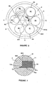
- the barrel comprises six bores 51 arranged axially and circumferentially spaced around the shaft 10a, in which pistons 9 are housed, the six pistons being referenced from 91 to 96 on the piston. figure 3 .
- a mechanical cam cooperates with the lower ends of the pistons opposite the cover, to cause the alternating movement of the pistons in the bores between a low position and a high position.
- a description of the displacement by the mechanical cam of the pistons on a turn will be made with reference to the figure 3 .
- the angular positions of the pistons relative to the stator 4 referenced A to E on the figure 3 correspond to particular positions of the pistons in their bore. In the angular position A, the piston is in the low position. The barrel being driven clockwise, as illustrated by the arrow referenced F, the pistons are maintained in this low position about 60 ° to the angular position B.
- the pistons are then brought to an intermediate low position to the angular position C, disposed at about 30 ° of the angular position B, and are held for about 30 ° in this intermediate low position to the angular position D, diametrically opposite to the angular position A.
- the pistons are then in their position. upward phase of discharge about 90 ° from the position D to the angular position E. In this position E, the pistons are in the upper position, their upper face 9a substantially flush with the upper face 5a of the barrel on which the bores open.
- the pistons are held in this high position about 60 ° to the position F.
- the pistons are then in their downward phase about 30 ° from the position F to the position A, in which the pistons are in position low.
- the figure 4 illustrates a partial view in longitudinal section of the barrel of the figure 3 after a rotation of about 50 °, the piston 93 being in the intermediate low position, the piston 94 in the low position.
- the lid 6 consists of a circular plate 61 pivotally mounted on the frame 1 about a horizontal axis 62.
- the lid is movable between an open position, illustrated in FIG. figure 2 , and a closed position, illustrated in figure 1 , in which the cover is in sliding contact by its so-called internal face 61a with the upper face 5a of the barrel.
- the lid is moved between its two positions by a motorized system 16.
- the lid is held in its closed position by means of assembly means 11, 12.
- the cylindrical wall of each bore defines a cylindrical chamber 8 ( figure 4 ) delimited on one side by the cover and on the other side by the upper face 9a of the piston which slides substantially sealingly between its low position and its upper position in the bore.
- the inner face 61a of the lid has a feed port 63, a discharge port 64 and a vacuum port 65.
- the supply port 63 is in communication via a feed channel 66 with the outlet of the hopper 3 assembled on the outer face of the lid, and is arranged to face a cylindrical chamber containing a piston in its low position.
- This supply orifice of dimensions slightly greater than the diameter of the cylindrical chambers, has an oval shape and is for example centered vis-à-vis a piston in the aforementioned angular position B.
- the hopper 3 comprises a propeller feed system 31 ( figure 1 ) rotated in the closed position of the cover by the aforementioned motor 10 for driving the barrel, via a transmission shaft 67.
- the supply port is equipped at its downstream end with a flat blade 70, generally in an arc.
- the blade is mounted in a recess 71 of the lid, so that its outer face 70a is flush with the inner surface 61a of the lid, the cutting edge 72 of the blade projecting from the wall of the feed channel 66.
- the wall of the supply duct 66 comprises a frustoconical portion 661 extending by a cylindrical outlet portion 662 defining the supply port of the lid, the receiving recess 71 of the blade being formed in this cylindrical outlet portion.
- the blade extends over an arc of about 180 ° and is removably mounted in the recess, for example by means of screws 73, to allow its replacement or sharpening.
- the elongated discharge port 64 is in communication with a lateral extrusion head 74, and is arranged and shaped so that at least two cylindrical chambers are continuously in communication therewith.
- the orifice has a main portion 641 ( figure 3 ) of circular general shape centered on a piston in position E, which extends downstream upstream relative to the direction of rotation of the barrel by a secondary portion 642 of lower depth than the main portion having a concave upstream end 642a.
- each bore 51 comprises three grooves vertical 52, of substantially semicircular cross section, disposed at 120 ° from each other and opening on the lower face 5b of the barrel.
- the height of the vertical grooves and the stroke of the pistons are defined so that the upper end 52a of each vertical groove is disposed beyond the upper face 9a of the pistons in their lower position to put the cylindrical chambers of the barrel into communication with the lower chamber of the stator defined under the barrel.
- This lower chamber is continuously vacuum under the start of the pusher via a vacuum pump.
- the vacuum pump 13 ( figure 1 ) is for example placed on the frame and is connected to the lower chamber of the stator via a first suction channel, extending in a cowling 14, and connected to a radial bore of the cylindrical wall of the housing.
- a first suction channel extending in a cowling 14
- a radial bore of the cylindrical wall of the housing As best seen on the figure 6 in the aforementioned intermediate low position of the pistons, the upper face of the piston is disposed above the vertical grooves to suppress the suction by the latter.
- Each piston head 900 comprises a metal body 901 through which the head is mounted at the end of the piston rod 902, a lining or cap 903 covering said body, made of a PTFE material, by interposing an intermediate layer 904 in an elastic material, such as a silicone elastomer.
- the cap comprises an upper circular wall extending by an annular wall, the latter being provided with a flange 905 defining the sealing surface through which the piston comes into sliding contact with the cylindrical wall of the bore.
- the flange has a generally trapezoidal cross section, the sealing surface being connected to the upper circular wall by a chamfer.
- the vertical grooves gradually fade in the upper part, the upper ends generally having a semi-conical cross section.
- each vertical groove extends over a height of about 8 millimeters (mm)
- the collar 905 has a height of about 4 mm
- the stroke of a piston between its high position and its position bass is about 55 mm
- the aforementioned evacuation port 65 of the lid opens onto a laterally extending channel whose inlet 68 comes into communication, when closing the lid, with a second suction channel 15 of the pump.
- vacuum mounted on the frame 1.
- the vacuum port is disposed downstream of the supply port relative to the direction of rotation F of the cylinder, so as to be substantially vis-à-vis the piston in position A.
- the inner face 61a is provided with one or more grooves 69 opening on the vacuum port.
- the arc on which the groove or grooves extend is determined so that each cylindrical chamber moving from said vacuum port to the supply port is under vacuum.
- the groove or grooves are formed by one or more removably mounted plates, for example screws, in a recess of the cover to match the type and number of grooves to the desired degree of suction. This vacuum via the vertical grooves 52 and the vacuum port 65 and ensures substantially homogeneous filling by suction of the cylindrical chambers with the product P from the hopper.
- the piston referenced 95 is in the aforementioned angular position A, in the low position and vis-à-vis the vacuum port.
- the cylindrical chamber associated with this piston is evacuated both via the vertical grooves and the vacuum port.
- the piston 94 is also in the lower position, vis-à-vis the grooves 69 for evacuation, and begins its filling phase vis-à-vis the supply port.
- the product P begins to penetrate into the cylindrical chamber under the effect of the suction obtained by the vacuum opening via the grooves. and the vertical grooves.
- This passage to an intermediate position before the start of the upward phase of the pistons discharge avoids that the suction from the bottom alters the flow of the piston in start of repression.
- This passage in the intermediate low position is performed when the cylindrical chamber is still in communication with the supply port so as not to compress the minced meat contained in the chamber cylindrical and discharge a small portion to the supply port. From the position D, the piston begins its ascending phase in communication with the discharge port, its flow is accumulated to that of the piston arranged upstream.
- the pump according to the invention can be used for the manufacture of a continuous sausage from which sausages are made, or for the portioning for example of minced meat comprising large pieces of muscle, the barrel being rotated in a discontinuous manner. .
- the evacuation of the cylindrical chambers from below is obtained by vertical channels opening on the upper face of the pistons. Inserts mounted mobile in said channels may then be provided to close said channels in the intermediate low position of the pistons.
Landscapes
- Engineering & Computer Science (AREA)
- Mechanical Engineering (AREA)
- General Engineering & Computer Science (AREA)
- Life Sciences & Earth Sciences (AREA)
- Wood Science & Technology (AREA)
- Zoology (AREA)
- Food Science & Technology (AREA)
- Processing Of Meat And Fish (AREA)
- Reciprocating Pumps (AREA)
- Lubrication Of Internal Combustion Engines (AREA)
- Compressor (AREA)
- Applications Or Details Of Rotary Compressors (AREA)
Claims (10)
- Rotationspumpe mit Kolben für halbfeste Produkte, insbesondere für Hackfleisch, die aufweist- einen Ständer (4), der einen zylindrischen Hohlraum definiert,- einen Rotor oder eine Trommel (5), der/die in dem zylindrischen Hohlraum liegt und dazu geeignet ist, von einem Motor (10) zum Rotieren gebracht zu werden, wobei der Rotor eine Gruppe von in Umfangsrichtung liegenden Bohrungen (51) aufweist, in denen die Kolben (9) angebracht sind,- eine mechanische Nocke, die mit den Kolben zusammenwirkt, um während der Rotation der Trommel eine alternierende Hin- und Herbewegung der Kolben zwischen einer Grundstellung und einer Hochstellung herbeizuführen,- einen Deckel (6), der den zylindrischen Hohlraum schließt,- eine Einfüllöffnung (63), die mit mindestens einer zylindrischen Kammer in Kontakt steht, die durch eine zylindrische Bohrung der Trommel und ihres verbundenen Kolbens ausgebildet ist, und die Einfüllöffnungdazu vorgesehen ist, mit einem Trichter (3) verbunden zu sein,- eine Anstauöffnung (64), die dazu geeignet ist, gleichzeitig in Kontakt mit mindestens zwei zylindrischen, aufeinander folgenden Kammern zu kommen, und- Evakuiermittel der zylindrischen Kammern (8), zu deren Befüllung,- die dadurch gekennzeichnet ist, dass die Evakuiermittel mindestens eine Vakuumleitung (52) aufweisen, die in den inneren Teil jeder zylindrischen Kammer mündet, wobei die Evakuiermittel dazu geeignet sind, über den Boden jede zylindrische Kammer mittels deren Vakuumleitung zu evakuieren, wenn der damit verbundene Kolben in Grundstellung ist.
- Pumpe nach Anspruch 1, die dadurch gekennzeichnet ist, dass die Evakuiermittel dazu geeignet sind, die Evakuierung jeder zylindrischen Kammer (8) über deren Vakuumleitung (52) vorab mittels Verlagerung der zylindrischen Kammer gegenüber zur Anstauöffnung (64) zu stoppen.
- Pumpe nach Anspruch 1 oder 2, die dadurch gekennzeichnet ist, dass jede zylindrische Kammer (8) mindestens eine Vakuumleitung (52) aufweist, die an der zylindrischen Wand der Bohrung (51) ausgebildet ist.
- Pumpe nach Anspruch 3, die dadurch gekennzeichnet ist, dass jede Vakuumleitung aus einem senkrechten Durchlass (52) gebildet ist, der an der zylindrischen Wand der Bohrung (51) ausgebildet ist, wobei der Durchlass sich von der inneren Fläche (5b) der Trommel bis zu einer Höhe erstreckt, die ausreichend ist, um in die zylindrische Kammer (8) hinein zu reichen, wenn sich der Kolben (9) in Grundstellung befindet, wobei die Evakuiermittel dazu geeignet sind, die innere Kammer des Ständers (4) zu evakuieren, in die die vertikalen Durchlässe münden.
- Pumpe nach Anspruch 4, die dadurch gekennzeichnet ist, dass jeder Kolben (9) dazu geeignet ist, mittels der mechanischen Nocke aus ihrer Grundstellung in eine Zwischengrundstellung bewegt zu werden, in der der Kolben die Vakuumleitung(en) (52) verschließt, wobei die Bewegung oberhalb der Anstauöffnung (64) ausgeführt wird, wenn sich der Kolben zumindest teilweise gegenüber der Einfüllöffnung (63) befindet.
- Pumpe nach einem der vorhergehenden Ansprüche, die dadurch gekennzeichnet ist, dass jede zylindrische Kammer (8) mindestens zwei Vakuumleitungen (52) aufweist, die in einem regelmäßigen Winkelabstand verteilt sind.
- Pumpe nach einem der vorhergehenden Ansprüche, dadurch gekennzeichnet, dass jeder Kolben (9) einen Kolbenkopf (900) aufweist, der mit einer Kolbenstange (902) verbunden ist, wobei der Kopf einen Körper (903) umfasst, der mit einem Belag (904) aus einem Material bedeckt ist, das Gleiteigenschaften aufweist, wodurch zwischen dem Körper und dem Belag eine Zwischenschicht (905) eingelegt wird, die elastische Eigenschaften hat, wobei der Belag eine Abdichtungsoberfläche bildet, über die der Kolben (9) gleitend, im Wesentlichen in abdichtender Weise, mit der zylindrischen Wand der Bohrung (51) in Verbindung steht.
- Pumpe nach einem der vorhergehenden Ansprüche, die dadurch gekennzeichnet ist, dass die Evakuiermittel ferner eine Vakuumöffnung (65) zum-Evakuieren über den oberen Bereich der Kammern aufweisen, wobei die Pumpe ein Vakuumpumpensystem (13) aufweist, mit dem zugleich die Vakuumleitungen (52) der zylindrischen Kammern, und die Vakuumöffnung (65) verbunden sind.
- Pumpe nach einem der vorhergehenden Ansprüche, die dadurch gekennzeichnet ist, dass die zylindrischen Kammern (8) in axialer Richtung ausgerichtet sind, wobei die Kolben (9) parallel zur Rotationsachse der Trommel ausgerichtet werden können, und der Deckel (6) mit einer Einfüllöffnung (63) und einer Anstauöffnung (64) ausgestattet ist.
- Pumpe nach einem der vorhergehenden Ansprüche, die dadurch gekennzeichnet ist, dass sie darüber hinaus Schneidemittel aufweist, die ein Blatt (70) umfassen, das entlang des Rands hinter der Einfüllöffnung (63) vorgesehen ist, um die Produktstücke zu schneiden, die aus den zylindrischen Kammern bei ihrer Passage über die Einfüllöffnung herausragen.
Applications Claiming Priority (2)
| Application Number | Priority Date | Filing Date | Title |
|---|---|---|---|
| FR0503554A FR2884287B1 (fr) | 2005-04-11 | 2005-04-11 | Pompe rotative a pistons |
| PCT/FR2006/000545 WO2006108935A1 (fr) | 2005-04-11 | 2006-03-13 | Pompe rotative a pistons |
Publications (2)
| Publication Number | Publication Date |
|---|---|
| EP1869320A1 EP1869320A1 (de) | 2007-12-26 |
| EP1869320B1 true EP1869320B1 (de) | 2008-07-30 |
Family
ID=34955246
Family Applications (1)
| Application Number | Title | Priority Date | Filing Date |
|---|---|---|---|
| EP06726074A Expired - Lifetime EP1869320B1 (de) | 2005-04-11 | 2006-03-13 | Rotationskolbenpumpe |
Country Status (9)
| Country | Link |
|---|---|
| US (1) | US7819726B2 (de) |
| EP (1) | EP1869320B1 (de) |
| JP (1) | JP5113037B2 (de) |
| AT (1) | ATE403084T1 (de) |
| BR (1) | BRPI0609640B1 (de) |
| DE (1) | DE602006002034D1 (de) |
| ES (1) | ES2309956T3 (de) |
| FR (1) | FR2884287B1 (de) |
| WO (1) | WO2006108935A1 (de) |
Cited By (2)
| Publication number | Priority date | Publication date | Assignee | Title |
|---|---|---|---|---|
| EP2873325A2 (de) | 2013-11-15 | 2015-05-20 | Heinrich Frey Maschinenbau GmbH | Abfüllvorrichtung |
| DE102014116554B3 (de) * | 2014-11-12 | 2015-11-12 | Heinrich Frey Maschinenbau Gmbh | Abfüllvorrichtung |
Families Citing this family (4)
| Publication number | Priority date | Publication date | Assignee | Title |
|---|---|---|---|---|
| FR2915348B1 (fr) * | 2007-04-27 | 2009-07-10 | Nijal Soc Par Actions Simplifi | Dispositif de fabrication de portions de produits alimentaires texturees |
| ES2537111T3 (es) * | 2010-12-22 | 2015-06-02 | Albert Handtmann Maschinenfabrik Gmbh & Co. Kg | Dispositivo y procedimiento para la distribución del aire residual en masas pastosas, en particular para la elaboración de embutidos |
| ES2427417T3 (es) * | 2011-05-20 | 2013-10-30 | Albert Handtmann Maschinenfabrik Gmbh & Co. Kg | Regulador de vacío en una llenadora al vacío sin aporte de aire exterior |
| EP3329782B1 (de) * | 2016-12-05 | 2019-02-13 | Albert Handtmann Maschinenfabrik GmbH & Co. KG | Füllmaschine und verfahren zum abfüllen flüssiger oder pastöser massen mit externem sammelbehälter |
Family Cites Families (11)
| Publication number | Priority date | Publication date | Assignee | Title |
|---|---|---|---|---|
| FR1325528A (fr) * | 1962-06-20 | 1963-04-26 | Machine à pistons, à marche continue, pour la fabrication des saucisses | |
| ES400102A1 (es) * | 1971-02-24 | 1975-07-16 | Battista Righele | Mejoras en la construccion de bombas para ensacadoras en forma continua de carne picada. |
| US3908536A (en) * | 1974-10-09 | 1975-09-30 | Chemetron Corp | Vacuumizing apparatus with internal flow control valve |
| US3922755A (en) * | 1974-12-03 | 1975-12-02 | Righele Giovanni | Rotary pump for feeding a continuous sausage-making machine |
| IT7922544U1 (it) * | 1979-09-18 | 1981-03-18 | Righele Giovanni | Apparecchio porzionatore attorcigliatore per catene di insaccati. |
| IT8711588V0 (it) * | 1987-03-19 | 1987-03-19 | Volentieri & C Omet | Una macchina insaccatrice con rotore di spinta a pistoni sagomati a settori di corona circolare e con tenute per evitare ristagno e perdite di sostenze alimentari. |
| US5197917A (en) * | 1991-10-11 | 1993-03-30 | Stork Gamco, Inc. | Apparatus for removing skin from animal parts |
| DE19916582C2 (de) * | 1999-04-13 | 2001-04-26 | Handtmann Albert Maschf | Verfahren und Vakuumfüller zum Abfüllen einer pastösen Masse |
| US6645917B2 (en) * | 2002-03-28 | 2003-11-11 | Council Of Scientific And Industrial Research | Composition for hybrid seed production, process for the preparation of such composition and use thereof |
| US7220176B2 (en) * | 2004-03-03 | 2007-05-22 | Tyson Fresh Meats, Inc. | System and method for production of exact weight ground meat |
| DE502006000842D1 (de) * | 2006-03-02 | 2008-07-10 | Handtmann Albert Maschf | Füllmaschine und Verfahren zum Zuführen von pastösen Massen aus einem Trichter in ein Förderwerk |
-
2005
- 2005-04-11 FR FR0503554A patent/FR2884287B1/fr not_active Expired - Fee Related
-
2006
- 2006-03-13 AT AT06726074T patent/ATE403084T1/de active
- 2006-03-13 EP EP06726074A patent/EP1869320B1/de not_active Expired - Lifetime
- 2006-03-13 ES ES06726074T patent/ES2309956T3/es not_active Expired - Lifetime
- 2006-03-13 JP JP2008505920A patent/JP5113037B2/ja not_active Expired - Lifetime
- 2006-03-13 WO PCT/FR2006/000545 patent/WO2006108935A1/fr not_active Ceased
- 2006-03-13 US US11/911,147 patent/US7819726B2/en active Active
- 2006-03-13 BR BRPI0609640-9A patent/BRPI0609640B1/pt active IP Right Grant
- 2006-03-13 DE DE602006002034T patent/DE602006002034D1/de not_active Expired - Lifetime
Cited By (5)
| Publication number | Priority date | Publication date | Assignee | Title |
|---|---|---|---|---|
| EP2873325A2 (de) | 2013-11-15 | 2015-05-20 | Heinrich Frey Maschinenbau GmbH | Abfüllvorrichtung |
| EP2873326A1 (de) | 2013-11-15 | 2015-05-20 | Heinrich Frey Maschinenbau GmbH | Abfüllvorrichtung |
| DE102013223364A1 (de) | 2013-11-15 | 2015-05-21 | Heinrich Frey Maschinenbau Gmbh | Abfüllvorrichtung |
| DE102014116554B3 (de) * | 2014-11-12 | 2015-11-12 | Heinrich Frey Maschinenbau Gmbh | Abfüllvorrichtung |
| EP3020282A1 (de) | 2014-11-12 | 2016-05-18 | Heinrich Frey Maschinenbau GmbH | Abfüllvorrichtung |
Also Published As
| Publication number | Publication date |
|---|---|
| ATE403084T1 (de) | 2008-08-15 |
| US20080175725A1 (en) | 2008-07-24 |
| BRPI0609640A2 (pt) | 2010-04-20 |
| JP2008536051A (ja) | 2008-09-04 |
| WO2006108935A1 (fr) | 2006-10-19 |
| ES2309956T3 (es) | 2008-12-16 |
| DE602006002034D1 (de) | 2008-09-11 |
| EP1869320A1 (de) | 2007-12-26 |
| FR2884287B1 (fr) | 2007-05-18 |
| US7819726B2 (en) | 2010-10-26 |
| FR2884287A1 (fr) | 2006-10-13 |
| BRPI0609640B1 (pt) | 2018-05-02 |
| JP5113037B2 (ja) | 2013-01-09 |
Similar Documents
| Publication | Publication Date | Title |
|---|---|---|
| EP2139343B1 (de) | Vorrichtung zur herstellung texturierter teile von lebensmittelprodukten | |
| FR2550777A1 (fr) | Dispositif pour vider des recipients contenant des produits de viscosite elevee | |
| EP1869320A1 (de) | Rotationskolbenpumpe | |
| EP2916963B1 (de) | Flüssigkeitsproduktbehälter | |
| FR2608224A1 (fr) | Pompe a pistons axiaux | |
| FR2936683A1 (fr) | Dispositif de fabrication en continu par cuisson extrusion d'un produit alimentaire contenant des morceaux entiers et solides et machine d'extrusion equipee d'un tel dispositif | |
| WO2017072471A1 (fr) | Système et procédé pour former des steaks hachés | |
| EP0452385A1 (de) | Vorrichtung zum dosieren von erzeugnissen in pastenform, insbesondere fleisch oder sonstigen proteinemulsionen. | |
| EP2438818B1 (de) | Verfahren und Vorrichtung zum Herstellen von Portionen von Lebensmittelprodukten, die mit einer Garnierung versehen sind. | |
| EP1391702A2 (de) | Dosiermaschine | |
| FR2494959A1 (fr) | Appareil pour mouler une matiere comestible | |
| EP3909430A1 (de) | Vorrichtung zum portionieren von würsten | |
| FR2802176A1 (fr) | Procede et dispositif pour conditionner un solide, notamment alimentaire, dans un recipient tel que flacon | |
| EP0192517B1 (de) | Dosiervorrichtung, insbesondere für Nahrungsprodukte | |
| EP1394517A1 (de) | Dosiermaschine mit einem Zylinder | |
| FR2699966A1 (fr) | Machine à piston comportant un organe de distribution rotatif. | |
| EP2103218B1 (de) | Trichter mit einer Vorrichtung zur Erleichterung der Strömung von Teig von Bäckereien, Konditoreien oder Ähnlichen, entlang einer Wand | |
| EP3744180B1 (de) | Verfahren zum verpacken von hackfleisch, und anlage zur umsetzung dieses verfahrens | |
| EP0618363A1 (de) | Flügelzellenpumpe | |
| EP4652845A1 (de) | Vorrichtung zum formen von teigwaren, anlage und verfahren zu deren herstellung | |
| EP3161314B1 (de) | Kolbenpumpe mit positiver verdrängung und drehverteiler | |
| FR2605288A1 (fr) | Perfectionnements apportes aux machines de remplissage sous pression et de dosage de produits alimentaires | |
| EP1032806B1 (de) | Vorrichtung zur volumendosierung | |
| EP1887222B1 (de) | Verbesserung von Radialkolbenpumpen | |
| CA3125677A1 (en) | Adjustable suspension for a bicycle |
Legal Events
| Date | Code | Title | Description |
|---|---|---|---|
| PUAI | Public reference made under article 153(3) epc to a published international application that has entered the european phase |
Free format text: ORIGINAL CODE: 0009012 |
|
| 17P | Request for examination filed |
Effective date: 20070924 |
|
| AK | Designated contracting states |
Kind code of ref document: A1 Designated state(s): AT BE BG CH CY CZ DE DK EE ES FI FR GB GR HU IE IS IT LI LT LU LV MC NL PL PT RO SE SI SK TR |
|
| GRAP | Despatch of communication of intention to grant a patent |
Free format text: ORIGINAL CODE: EPIDOSNIGR1 |
|
| RAP1 | Party data changed (applicant data changed or rights of an application transferred) |
Owner name: STORK FOOD SYSTEMS FRANCE |
|
| GRAS | Grant fee paid |
Free format text: ORIGINAL CODE: EPIDOSNIGR3 |
|
| GRAA | (expected) grant |
Free format text: ORIGINAL CODE: 0009210 |
|
| DAX | Request for extension of the european patent (deleted) | ||
| AK | Designated contracting states |
Kind code of ref document: B1 Designated state(s): AT BE BG CH CY CZ DE DK EE ES FI FR GB GR HU IE IS IT LI LT LU LV MC NL PL PT RO SE SI SK TR |
|
| REG | Reference to a national code |
Ref country code: GB Ref legal event code: FG4D Free format text: NOT ENGLISH |
|
| REG | Reference to a national code |
Ref country code: CH Ref legal event code: EP |
|
| REF | Corresponds to: |
Ref document number: 602006002034 Country of ref document: DE Date of ref document: 20080911 Kind code of ref document: P |
|
| REG | Reference to a national code |
Ref country code: IE Ref legal event code: FG4D Free format text: LANGUAGE OF EP DOCUMENT: FRENCH |
|
| REG | Reference to a national code |
Ref country code: ES Ref legal event code: FG2A Ref document number: 2309956 Country of ref document: ES Kind code of ref document: T3 |
|
| PG25 | Lapsed in a contracting state [announced via postgrant information from national office to epo] |
Ref country code: IS Free format text: LAPSE BECAUSE OF FAILURE TO SUBMIT A TRANSLATION OF THE DESCRIPTION OR TO PAY THE FEE WITHIN THE PRESCRIBED TIME-LIMIT Effective date: 20081130 Ref country code: LT Free format text: LAPSE BECAUSE OF FAILURE TO SUBMIT A TRANSLATION OF THE DESCRIPTION OR TO PAY THE FEE WITHIN THE PRESCRIBED TIME-LIMIT Effective date: 20080730 |
|
| PG25 | Lapsed in a contracting state [announced via postgrant information from national office to epo] |
Ref country code: LV Free format text: LAPSE BECAUSE OF FAILURE TO SUBMIT A TRANSLATION OF THE DESCRIPTION OR TO PAY THE FEE WITHIN THE PRESCRIBED TIME-LIMIT Effective date: 20080730 Ref country code: BG Free format text: LAPSE BECAUSE OF FAILURE TO SUBMIT A TRANSLATION OF THE DESCRIPTION OR TO PAY THE FEE WITHIN THE PRESCRIBED TIME-LIMIT Effective date: 20081030 Ref country code: PT Free format text: LAPSE BECAUSE OF FAILURE TO SUBMIT A TRANSLATION OF THE DESCRIPTION OR TO PAY THE FEE WITHIN THE PRESCRIBED TIME-LIMIT Effective date: 20081230 Ref country code: SI Free format text: LAPSE BECAUSE OF FAILURE TO SUBMIT A TRANSLATION OF THE DESCRIPTION OR TO PAY THE FEE WITHIN THE PRESCRIBED TIME-LIMIT Effective date: 20080730 Ref country code: FI Free format text: LAPSE BECAUSE OF FAILURE TO SUBMIT A TRANSLATION OF THE DESCRIPTION OR TO PAY THE FEE WITHIN THE PRESCRIBED TIME-LIMIT Effective date: 20080730 |
|
| REG | Reference to a national code |
Ref country code: IE Ref legal event code: FD4D |
|
| PG25 | Lapsed in a contracting state [announced via postgrant information from national office to epo] |
Ref country code: DK Free format text: LAPSE BECAUSE OF FAILURE TO SUBMIT A TRANSLATION OF THE DESCRIPTION OR TO PAY THE FEE WITHIN THE PRESCRIBED TIME-LIMIT Effective date: 20080730 Ref country code: EE Free format text: LAPSE BECAUSE OF FAILURE TO SUBMIT A TRANSLATION OF THE DESCRIPTION OR TO PAY THE FEE WITHIN THE PRESCRIBED TIME-LIMIT Effective date: 20080730 Ref country code: IE Free format text: LAPSE BECAUSE OF FAILURE TO SUBMIT A TRANSLATION OF THE DESCRIPTION OR TO PAY THE FEE WITHIN THE PRESCRIBED TIME-LIMIT Effective date: 20080730 |
|
| PG25 | Lapsed in a contracting state [announced via postgrant information from national office to epo] |
Ref country code: SK Free format text: LAPSE BECAUSE OF FAILURE TO SUBMIT A TRANSLATION OF THE DESCRIPTION OR TO PAY THE FEE WITHIN THE PRESCRIBED TIME-LIMIT Effective date: 20080730 Ref country code: RO Free format text: LAPSE BECAUSE OF FAILURE TO SUBMIT A TRANSLATION OF THE DESCRIPTION OR TO PAY THE FEE WITHIN THE PRESCRIBED TIME-LIMIT Effective date: 20080730 Ref country code: CZ Free format text: LAPSE BECAUSE OF FAILURE TO SUBMIT A TRANSLATION OF THE DESCRIPTION OR TO PAY THE FEE WITHIN THE PRESCRIBED TIME-LIMIT Effective date: 20080730 |
|
| PLBE | No opposition filed within time limit |
Free format text: ORIGINAL CODE: 0009261 |
|
| STAA | Information on the status of an ep patent application or granted ep patent |
Free format text: STATUS: NO OPPOSITION FILED WITHIN TIME LIMIT |
|
| 26N | No opposition filed |
Effective date: 20090506 |
|
| BERE | Be: lapsed |
Owner name: STORK FOOD SYSTEMS FRANCE Effective date: 20090331 |
|
| PG25 | Lapsed in a contracting state [announced via postgrant information from national office to epo] |
Ref country code: MC Free format text: LAPSE BECAUSE OF NON-PAYMENT OF DUE FEES Effective date: 20090331 |
|
| PG25 | Lapsed in a contracting state [announced via postgrant information from national office to epo] |
Ref country code: SE Free format text: LAPSE BECAUSE OF FAILURE TO SUBMIT A TRANSLATION OF THE DESCRIPTION OR TO PAY THE FEE WITHIN THE PRESCRIBED TIME-LIMIT Effective date: 20081030 |
|
| PG25 | Lapsed in a contracting state [announced via postgrant information from national office to epo] |
Ref country code: BE Free format text: LAPSE BECAUSE OF NON-PAYMENT OF DUE FEES Effective date: 20090331 |
|
| PG25 | Lapsed in a contracting state [announced via postgrant information from national office to epo] |
Ref country code: PL Free format text: LAPSE BECAUSE OF FAILURE TO SUBMIT A TRANSLATION OF THE DESCRIPTION OR TO PAY THE FEE WITHIN THE PRESCRIBED TIME-LIMIT Effective date: 20080730 |
|
| PG25 | Lapsed in a contracting state [announced via postgrant information from national office to epo] |
Ref country code: GR Free format text: LAPSE BECAUSE OF FAILURE TO SUBMIT A TRANSLATION OF THE DESCRIPTION OR TO PAY THE FEE WITHIN THE PRESCRIBED TIME-LIMIT Effective date: 20081031 |
|
| REG | Reference to a national code |
Ref country code: CH Ref legal event code: PL |
|
| PG25 | Lapsed in a contracting state [announced via postgrant information from national office to epo] |
Ref country code: LI Free format text: LAPSE BECAUSE OF NON-PAYMENT OF DUE FEES Effective date: 20100331 Ref country code: CH Free format text: LAPSE BECAUSE OF NON-PAYMENT OF DUE FEES Effective date: 20100331 |
|
| PG25 | Lapsed in a contracting state [announced via postgrant information from national office to epo] |
Ref country code: LU Free format text: LAPSE BECAUSE OF NON-PAYMENT OF DUE FEES Effective date: 20090313 |
|
| PG25 | Lapsed in a contracting state [announced via postgrant information from national office to epo] |
Ref country code: HU Free format text: LAPSE BECAUSE OF FAILURE TO SUBMIT A TRANSLATION OF THE DESCRIPTION OR TO PAY THE FEE WITHIN THE PRESCRIBED TIME-LIMIT Effective date: 20090131 |
|
| PG25 | Lapsed in a contracting state [announced via postgrant information from national office to epo] |
Ref country code: TR Free format text: LAPSE BECAUSE OF FAILURE TO SUBMIT A TRANSLATION OF THE DESCRIPTION OR TO PAY THE FEE WITHIN THE PRESCRIBED TIME-LIMIT Effective date: 20080730 |
|
| PG25 | Lapsed in a contracting state [announced via postgrant information from national office to epo] |
Ref country code: CY Free format text: LAPSE BECAUSE OF FAILURE TO SUBMIT A TRANSLATION OF THE DESCRIPTION OR TO PAY THE FEE WITHIN THE PRESCRIBED TIME-LIMIT Effective date: 20080730 |
|
| REG | Reference to a national code |
Ref country code: FR Ref legal event code: CD Owner name: MAREL FRANCE, FR Effective date: 20130416 Ref country code: FR Ref legal event code: TP Owner name: MAREL FRANCE, FR Effective date: 20130416 |
|
| PGFP | Annual fee paid to national office [announced via postgrant information from national office to epo] |
Ref country code: AT Payment date: 20130226 Year of fee payment: 8 |
|
| REG | Reference to a national code |
Ref country code: DE Ref legal event code: R082 Ref document number: 602006002034 Country of ref document: DE Representative=s name: BOETERS & LIECK, DE |
|
| REG | Reference to a national code |
Ref country code: GB Ref legal event code: 732E Free format text: REGISTERED BETWEEN 20140522 AND 20140528 |
|
| REG | Reference to a national code |
Ref country code: DE Ref legal event code: R081 Ref document number: 602006002034 Country of ref document: DE Owner name: MAREL FRANCE, FR Free format text: FORMER OWNER: STORK FOOD SYSTEMS FRANCE, BAUD, FR Effective date: 20140611 Ref country code: DE Ref legal event code: R082 Ref document number: 602006002034 Country of ref document: DE Representative=s name: BOETERS & LIECK, DE Effective date: 20140611 Ref country code: DE Ref legal event code: R081 Ref document number: 602006002034 Country of ref document: DE Owner name: HEINRICH FREY MASCHINENBAU GMBH, DE Free format text: FORMER OWNER: STORK FOOD SYSTEMS FRANCE, BAUD, FR Effective date: 20140611 Ref country code: DE Ref legal event code: R082 Ref document number: 602006002034 Country of ref document: DE Representative=s name: MANITZ, FINSTERWALD & PARTNER GBR, DE Effective date: 20140611 Ref country code: DE Ref legal event code: R082 Ref document number: 602006002034 Country of ref document: DE Representative=s name: MANITZ FINSTERWALD PATENTANWAELTE PARTMBB, DE Effective date: 20140611 |
|
| REG | Reference to a national code |
Ref country code: NL Ref legal event code: TD Effective date: 20140731 Ref country code: NL Ref legal event code: SD Effective date: 20140731 |
|
| REG | Reference to a national code |
Ref country code: ES Ref legal event code: PC2A Owner name: MAREL FRANCE Effective date: 20140903 |
|
| REG | Reference to a national code |
Ref country code: AT Ref legal event code: MM01 Ref document number: 403084 Country of ref document: AT Kind code of ref document: T Effective date: 20140313 |
|
| PG25 | Lapsed in a contracting state [announced via postgrant information from national office to epo] |
Ref country code: AT Free format text: LAPSE BECAUSE OF NON-PAYMENT OF DUE FEES Effective date: 20140313 |
|
| REG | Reference to a national code |
Ref country code: FR Ref legal event code: PLFP Year of fee payment: 11 |
|
| REG | Reference to a national code |
Ref country code: DE Ref legal event code: R082 Ref document number: 602006002034 Country of ref document: DE Representative=s name: MANITZ FINSTERWALD PATENT- UND RECHTSANWALTSPA, DE Ref country code: DE Ref legal event code: R082 Ref document number: 602006002034 Country of ref document: DE Representative=s name: MANITZ, FINSTERWALD & PARTNER GBR, DE Ref country code: DE Ref legal event code: R081 Ref document number: 602006002034 Country of ref document: DE Owner name: HEINRICH FREY MASCHINENBAU GMBH, DE Free format text: FORMER OWNER: MAREL FRANCE, BAUD, FR Ref country code: DE Ref legal event code: R082 Ref document number: 602006002034 Country of ref document: DE Representative=s name: MANITZ FINSTERWALD PATENTANWAELTE PARTMBB, DE |
|
| REG | Reference to a national code |
Ref country code: FR Ref legal event code: TP Owner name: HEINRICH FREY MASCHINENBAU GMBH, DE Effective date: 20160502 |
|
| REG | Reference to a national code |
Ref country code: NL Ref legal event code: PD Owner name: HEINRICH FREY MASCHINENBAU GMBH; DE Free format text: DETAILS ASSIGNMENT: CHANGE OF OWNER(S), ASSIGNMENT; FORMER OWNER NAME: MAREL FRANCE Effective date: 20161025 |
|
| REG | Reference to a national code |
Ref country code: ES Ref legal event code: PC2A Owner name: HEINRICH FREY MASCHINENBAU GMBH Effective date: 20161222 |
|
| REG | Reference to a national code |
Ref country code: FR Ref legal event code: PLFP Year of fee payment: 12 |
|
| REG | Reference to a national code |
Ref country code: GB Ref legal event code: 732E Free format text: REGISTERED BETWEEN 20170406 AND 20170412 |
|
| REG | Reference to a national code |
Ref country code: FR Ref legal event code: PLFP Year of fee payment: 13 |
|
| PGFP | Annual fee paid to national office [announced via postgrant information from national office to epo] |
Ref country code: NL Payment date: 20250319 Year of fee payment: 20 |
|
| PGFP | Annual fee paid to national office [announced via postgrant information from national office to epo] |
Ref country code: FR Payment date: 20250325 Year of fee payment: 20 |
|
| PGFP | Annual fee paid to national office [announced via postgrant information from national office to epo] |
Ref country code: IT Payment date: 20250325 Year of fee payment: 20 Ref country code: GB Payment date: 20250321 Year of fee payment: 20 |
|
| PGFP | Annual fee paid to national office [announced via postgrant information from national office to epo] |
Ref country code: DE Payment date: 20250527 Year of fee payment: 20 |
|
| PGFP | Annual fee paid to national office [announced via postgrant information from national office to epo] |
Ref country code: ES Payment date: 20250425 Year of fee payment: 20 |
|
| REG | Reference to a national code |
Ref country code: DE Ref legal event code: R071 Ref document number: 602006002034 Country of ref document: DE |
|
| REG | Reference to a national code |
Ref country code: NL Ref legal event code: MK Effective date: 20260312 |
|
| REG | Reference to a national code |
Ref country code: ES Ref legal event code: FD2A Effective date: 20260326 |
|
| REG | Reference to a national code |
Ref country code: GB Ref legal event code: PE20 Expiry date: 20260312 |
|
| PG25 | Lapsed in a contracting state [announced via postgrant information from national office to epo] |
Ref country code: ES Free format text: LAPSE BECAUSE OF EXPIRATION OF PROTECTION Effective date: 20260314 |