EP1877204B1 - Verfahren und vorrichtung zur bandformsteuerung in warmwalzwerken - Google Patents
Verfahren und vorrichtung zur bandformsteuerung in warmwalzwerken Download PDFInfo
- Publication number
- EP1877204B1 EP1877204B1 EP06701147A EP06701147A EP1877204B1 EP 1877204 B1 EP1877204 B1 EP 1877204B1 EP 06701147 A EP06701147 A EP 06701147A EP 06701147 A EP06701147 A EP 06701147A EP 1877204 B1 EP1877204 B1 EP 1877204B1
- Authority
- EP
- European Patent Office
- Prior art keywords
- strip
- work
- zone
- rolls
- shape
- Prior art date
- Legal status (The legal status is an assumption and is not a legal conclusion. Google has not performed a legal analysis and makes no representation as to the accuracy of the status listed.)
- Expired - Lifetime
Links
Images


Classifications
-
- B—PERFORMING OPERATIONS; TRANSPORTING
- B21—MECHANICAL METAL-WORKING WITHOUT ESSENTIALLY REMOVING MATERIAL; PUNCHING METAL
- B21B—ROLLING OF METAL
- B21B37/00—Control devices or methods specially adapted for metal-rolling mills or the work produced thereby
- B21B37/28—Control of flatness or profile during rolling of strip, sheets or plates
- B21B37/30—Control of flatness or profile during rolling of strip, sheets or plates using roll camber control
- B21B37/32—Control of flatness or profile during rolling of strip, sheets or plates using roll camber control by cooling, heating or lubricating the rolls
-
- B—PERFORMING OPERATIONS; TRANSPORTING
- B21—MECHANICAL METAL-WORKING WITHOUT ESSENTIALLY REMOVING MATERIAL; PUNCHING METAL
- B21B—ROLLING OF METAL
- B21B27/00—Rolls, roll alloys or roll fabrication; Lubricating, cooling or heating rolls while in use
- B21B27/06—Lubricating, cooling or heating rolls
- B21B27/10—Lubricating, cooling or heating rolls externally
-
- B—PERFORMING OPERATIONS; TRANSPORTING
- B21—MECHANICAL METAL-WORKING WITHOUT ESSENTIALLY REMOVING MATERIAL; PUNCHING METAL
- B21B—ROLLING OF METAL
- B21B1/00—Metal-rolling methods or mills for making semi-finished products of solid or profiled cross-section; Sequence of operations in milling trains; Layout of rolling-mill plant, e.g. grouping of stands; Succession of passes or of sectional pass alternations
- B21B1/46—Metal-rolling methods or mills for making semi-finished products of solid or profiled cross-section; Sequence of operations in milling trains; Layout of rolling-mill plant, e.g. grouping of stands; Succession of passes or of sectional pass alternations for rolling metal immediately subsequent to continuous casting
- B21B1/463—Metal-rolling methods or mills for making semi-finished products of solid or profiled cross-section; Sequence of operations in milling trains; Layout of rolling-mill plant, e.g. grouping of stands; Succession of passes or of sectional pass alternations for rolling metal immediately subsequent to continuous casting in a continuous process, i.e. the cast not being cut before rolling
-
- B—PERFORMING OPERATIONS; TRANSPORTING
- B21—MECHANICAL METAL-WORKING WITHOUT ESSENTIALLY REMOVING MATERIAL; PUNCHING METAL
- B21B—ROLLING OF METAL
- B21B27/00—Rolls, roll alloys or roll fabrication; Lubricating, cooling or heating rolls while in use
- B21B27/06—Lubricating, cooling or heating rolls
- B21B27/10—Lubricating, cooling or heating rolls externally
- B21B2027/103—Lubricating, cooling or heating rolls externally cooling externally
-
- B—PERFORMING OPERATIONS; TRANSPORTING
- B21—MECHANICAL METAL-WORKING WITHOUT ESSENTIALLY REMOVING MATERIAL; PUNCHING METAL
- B21B—ROLLING OF METAL
- B21B37/00—Control devices or methods specially adapted for metal-rolling mills or the work produced thereby
- B21B37/74—Temperature control, e.g. by cooling or heating the rolls or the product
-
- Y—GENERAL TAGGING OF NEW TECHNOLOGICAL DEVELOPMENTS; GENERAL TAGGING OF CROSS-SECTIONAL TECHNOLOGIES SPANNING OVER SEVERAL SECTIONS OF THE IPC; TECHNICAL SUBJECTS COVERED BY FORMER USPC CROSS-REFERENCE ART COLLECTIONS [XRACs] AND DIGESTS
- Y10—TECHNICAL SUBJECTS COVERED BY FORMER USPC
- Y10T—TECHNICAL SUBJECTS COVERED BY FORMER US CLASSIFICATION
- Y10T29/00—Metal working
- Y10T29/49—Method of mechanical manufacture
- Y10T29/4998—Combined manufacture including applying or shaping of fluent material
- Y10T29/49988—Metal casting
- Y10T29/49991—Combined with rolling
Definitions
- This invention relates to hot rolling mills and particularly to those used continuous casting of thin steel strip a twin roll caster.
- molten metal is introduced between a pair of counter-rotated horizontal casting rolls which are cooled so that metal shells solidify on the moving roll surfaces, and are brought together at the nip between them to produce a solidified strip product delivered downwardly from the nip between the casting rolls.
- the term "nip" is used herein to refer to the general region at which the casting rolls are closest together.
- the molten metal may be poured from a ladle through a metal delivery system comprised of a tundish and a core nozzle located above the nip to form a casting pool of molten metal supported on the casting surfaces of the rolls above the nip and extending along the length of the nip. This casting pool is usually confined between refractory side plates or dams held in sliding engagement with the end surfaces of the rolls so as to dam the two ends of the casting pool against outflow.
- a sealed enclosure is provided beneath the casting rolls to receive the hot strip and through which the strip passes away from the strip caster, the enclosure containing an atmosphere which inhibits oxidation of the strip.
- the oxidation inhibiting atmosphere may be created by injecting a non-oxidizing gas, for example, an inert gas such as argon or nitrogen, or combustion exhaust gases which may be reducing gases.
- the enclosure may be sealed against ingress of oxygen containing atmosphere during operation of the strip caster.
- a thin strip is generally hot rolled in a hot rolling mill after the strip emerges from the caster to shape the thin strip.
- the mill roll gap profile should as near as possible to the cross-sectional profile of the incoming strip.
- Significant deviations between the incoming product profile and roll gap profile produces a localized shape defect in the outgoing rolled strip at the location across the strip width where the deviations occurs. If the roll gap thickness is less than the incoming strip thickness in that region relative to adjacent regions across the strip width, a buckle or loose defect occurs in the strip shape in that area producing a shape defect. This shape defect is characterized by lower than average tension stress. If the roll gap thickness is greater than the incoming strip thickness in that region relative to adjacent regions across the strip width, a tight or ridge strip shape defect will be produced in that area of the strip. The tight or ridge shape is characterized by higher than average tension stress.
- the roll gap profile is determined principally by the ground profile of the work rolls. However, under operating load, the roll gap profile is also determined by the material characteristics of the incoming strip, the ground profiles of the mill rolls, the stack deflection of the mill rolls, mill housing stretch, and thermal effects due to heat generated in the roll gap by rolling.
- mill actuators have been provided that are capable of dynamically influencing the roll gap profile by some compensation for these parameters to make the roll gap profile better approach conformance to the incoming strip profile.
- work roll bending jacks have been provided to affect symmetrical changes in the roll gap profile central region of the work rolls relative to regions adjacent the edges. The roll bending is capable of correcting symmetrical shape defects that are common to the central region and both edges of the strip.
- force cylinders can affect asymmetrical changes in the roll gap profile on one side relative to the other side.
- the roll force cylinders are capable of skewing or tilting the roll gap profile to correct for shape defects in the strip that occur asymmetrically at either side of the strip, with one side being tighter and the other side being looser than average tension stress across the strip.
- Another device available is the use of spray nozzles at the edges of the strip, particularly thicker strip, to adjust for crown drop at the edges of the strip by cooling in such way that the edges drop caused by the transverse flow behavior of the material during rolling can be reduced or minimised. See US Patent No. 5, 799,523 .
- JP-A-09267106 also describes spraying a rolling mill working roll over the width of the roll to the control crowning.
- the present invention provides a method and apparatus for localised modification of the roll gap profile to correct these types of shape defects.
- both the upper and lower work roll profiles can be controlled by thermal expansion or contraction of the work rolls sufficient to produce thin steel strip without pronounced shape defects and without causing localised buckling, ridges and edge wave in the strip.
- control of localised cooling can be accomplished by increasing the relative volume or velocity, or decreasing of temperature, of coolant sprayed through nozzles onto the work roll surfaces in the zone or zones of an observed strip shape buckle or loose area, causing the work roll diameter of either or both of the work rolls in that area to contract, increasing the roll gap profile, and effectively tightening the strip shape in that region to alleviate pronounced defects in the strip without causing localized buckling, ridges and edge wave in the strip.
- the control of localized cooling can be accomplished by internally controlling cooling the work surface of the work roll in zones across the work roll by localized control of temperature or volume water circulated through the work rolls adjacent the work surfaces.
- a method of producing thin cast strip with a controlled strip shape by continuous casting comprising the steps of:
- Suitable five zones can be provided so that quarter buckles can be inhibited.
- the number of zones provided may be increased to the number of nozzles that the geometry adjacent the work rolls permit to be positioned in a particular embodiment.
- There can be more than one row of nozzles e.g., two or more rows of nozzles, positioned adjacent the work surface so that adjacent zones may not necessarily be serviced by nozzles, in the same row.
- the nozzles can be positioned to overlap so that the regions of the work roll surface are covered at least across the portion where strip engages the work rolls, and typically beyond where strip engages the work rolls, to provide for effective localized controlling of cooling of the work roll surface under control.
- a zone could be serviced by two or more nozzles not all of which necessarily capable of individual control.
- the zones of controlled localized cooling should be such as to cover the surface of the work roll at least in the area where the strip encounters the work roll, but may extend substantially beyond the edge of the strip, and may include the entire work roll, to provide effective control of the strip shape.
- the sprays from nozzles on the work surface should not impinge on each other, because in so going the sprays can interfere with each other and reduce effective control in shaping of the work roll within a zone, and in turn reduce effective control the shaping of defects observed in the strip of the strip.
- the coolant is typically water, although other coolants may be utilized as desired.
- the localized controlling of cooling of the work surface of the work rolls in each zone thus can be accomplished by varying the flow volume, velocity and temperature of coolant impacting on the work surface of the work rolls in each zone.
- the method of producing thin cast strip with a controlled strip shape by continuous casting may comprise the additional steps of:
- the present invention also provides a thin cast strip plant for producing strip with a controlled strip shape by continuous casting comprising:
- the_ number of zones that can be provided in the hot rolling mill can be expanded to the number of localized cooling devices that can be provided with the geometry of a particular embodiment.
- There can be more than one row of localized cooling devices e.g., two or more rows of localised coding devices, such as nozzles, positioned adjacent the work surface so that adjacent zones may not necessarily be serviced by localized cooling devices in the same row.
- the localized cooling devices can be thus easily positioned to overlap so that the regions of the work roll surfaces are covered at least across the portion where strip engages the work rolls, and typically beyond where strip engages the work rolls, to provide for effective localized controlling of cooling of the work surface.
- a zone could be serviced by two or more localized cooling devices not all of which are capable of individual control.
- the localized cooling by the localized cooling devices in each zone may overlap between zones at the work surface of the work rolls to provide effective control of the shape of the work roll surface and the strip shape,
- the zones of controlled localized cooling should be such as to cover the surface of the work roll at least in the area where the strip encounters the work roll, but may extend substantially beyond the edge of the strip, and may include the entire work roll, to provide effective control of the strip shape.
- the sprays from nozzles onto the work roll surface should not impinge on each other to provide effective control in shaping of the work roll surface within a zone, and in turn effective control the shape observed in the strip in each zone
- the coolant is typically water, with other coolants utilized as desired.
- the localized controlling of cooling of the work surface of the work rolls in each zone thus can be accomplished by varying the volume, velocity and temperature of coolant impacting on the work surface of the work rolls in each zone.
- the localized controlling of cooling of the work surface of the work roll needs to have the thermal effect to locally expand and contract the diameter the work roll to make a substantial change in the roll gap, and affect the desired local roll shape control in each zone.
- This localized controlling of cooling of the work surface of the work roll is in addition to the coolant that may be sprayed on the work roll at the same time to cool the work roll.
- the effectiveness on the strip shape control depends upon the temperature differential between the work roll surface and the coolant, as well as the coolant volume and velocity sprayed onto or circulated within the particular zone of the work surface of the work roll.
- the coolant practice may be modified to minimize the fixed coolant volume while maintaining work roll surface temperatures within an acceptable range, e.g.
- the devices controlling localized cooling used for shape control may be turned completely off at the start of a casting campaign, or set at some intermediate level so that regulating the localized cooling devices can both expand and contract the work roll diameter in a zone. As local areas with loose shape are observed, the localized cooling devices can be regulated adjacent the upper and lower work rolls in the zone corresponding to where a shape defect is observed to contract or expand the work roll diameter, increase or decrease the relative roll gap and tighten or loosen the strip shape coming out of the hot rolling mill.
- the ratio of coolant volume for shape defect correction to uncontrolled spray volume for cooling of the work rolls is in the range from about 1 to 1 up to 3 to 1.
- the volume of the coolant from the controllable nozzles to effect localized cooling in each zone may be about 100% to 300% of the volume from the nozzles that are constantly spraying the work surface to cool the work roll.
- the actual total gallon per minute flow depends on the thickness of the strip being made, upon whether both the upper and lower work are being locally cooled, upon the setting of the main upper and/or lower work roll coolant supply valves, the temperature of the coolant, and the sizes of the individual spray nozzles (which may be the same or different for the spray nozzles used to generally cool the work rolls).
- the hot rolling mill may automatically control strip shape by providing sensors in a sensor roll positioned downstream of the mill to sense localized shape in the strip along the width of the strip, and a control system capable of controlling the flow of coolant sprayed on the work rolls in the individual zones through controllable localized cooling devices.
- the hot rolling mill can automatically adjust for shape defects sensed in the strip by regulating the localized cooling in each zone in the individual zones along the work surface of the work roll, and in turn controlling the shape of the surface of the work rolls of the mill and the shape of the thin steel strip.
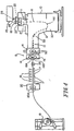
- the illustrated casting and rolling installation comprises a twin-roll caster denoted generally by 11 which produces thin cast steel strip 12 which passes into a transient path 10 across a guide table 13 to a pinch roll stand 14.
- thin cast strip 12 passes into and through hot rolling mill 15 comprised of back up rolls 16 and upper and lower work rolls 16A and 16B, where the thickness of the strip reduced.
- the strip 12, upon exiting the rolling mill 16, passes onto a run out table 17 where it may be forced cooled by water jets 18, and then through pinch roll stand 20 comprising a pair of pinch rolls 20A and to a coiler 19.
- Twin-roll caster 11 comprises a main machine frame 21 which supports a pair of laterally positioned casting rolls 22 having casting surfaces 22A and forming a nip 27 between them.
- Molten metal is supplied during a casting campaign from a ladle (not shown) to a tundish 23, through a refractory shroud 24 to a removable tundish 25 (also called distributor vessel or transition piece), and then through a metal delivery nozzle 26 (also called a core nozzle) between the casting rolls 22 above the nip 27.
- Removable tundish 25 is fitted with a lid 28. Molten steel is introduced into removable tundish 25 from tundish 23 via an outlet of shroud 24.
- the tundish 23 is fitted with a stopper rod and a slide gate valve (not shown) to selectively open and close the outlet of shroud 24 and effectively control the flow of molten metal from the tundish 23 to the caster.
- the molten metal flows from removable tundish 25 through an outlet and optionally to and through the delivery nozzle 26.
- Molten metal thus delivered to the casting rolls 22 forms a casting pool 30 above nip 27 supported by casting roll surfaces 22A.
- This casting pool is confined at the ends of the rolls by a pair of side dams or plates 28, which are applies to the ends of the rolls by a pair of thrusters (not shown) comprising hydraulic cylinder units connected to the side dams.
- the upper surface of the casting pool 30 (generally referred to as the "meniscus" level) may rise above the lower end of the delivery nozzle 26 so that the lower end of the delivery nozzle 26 is immersed within the casting pool.
- Casting rolls 22 are internally water cooled by coolant supply (not shown) and driven in counter rotational direction by drives (not shown) so that shells solidify on the moving casting roll surfaces and are brought together at the nip 27 to produce the thin cast strip 12, which is delivered downwardly from the nip between the casting rolls.
- the cast steel strip 12 passes within a sealed enclosure 10 to the guide table 13, which guides the strip to a pinch roll, stand 14 through which it exits sealed enclosure 10.
- the seal of the enclosure 10 may not be complete, but is appropriate to allow control of the atmosphere within the enclosure and access of oxygen to the cast strip within the enclosure as hereinafter described. After exiting the sealed enclosure 10, the strip may pass through further sealed enclosures (not shown) at the pinch roll stand 14.
- Enclosure 10 is formed by a number of separate wall sections which fit together at various seal connections to form a continuous enclosure wall. These sections comprise a first wall section 41 at the twin roll caster to enclose the casting rolls 22, and a wall enclosure 42 extending downwardly beneath first wall section 41 to form an opening that is in sealing engagement with the upper edges of a scrap box receptacle 40.
- a seal 43 between the scrap box receptacle 40 and the enclosure wall 42 may be formed by a knife and sand seal around the opening in enclosure wall 42, which can be established and broken by vertical movement of the scrap box receptacle 40 relative to enclosure wall 42.
- the upper edge of the scrap box receptacle 40 may be formed with an upwardly facing channel which is filled with sand and which receives a knife flange depending downwardly around the opening in enclosure wall 42.
- Seal 43 is formed by raising the scrap box receptacle 40 to cause the knife flange to penetrate the sand in the channel to establish the seal. This seal 43 can be broken by lowering the scrap box receptacle 40 from its operative position, preparatory to movement away from the caster to a scrap discharge position (not shown).
- Scrap box receptacle 40 is mounted on a carriage 45 fitted with wheels 46 which run on rails 47, whereby the scrap box receptacle can be moved to the scrap discharge position.
- Carriage 45 is fitted with a set of powered screw jacks 48 operable to lift the scrap box receptacle 40 from a lowered position, where it is spaced from the enclosure wall 42, to a raised position where the knife flange penetrates the sand to form seal 43 between the two.
- Sealed enclosure 10 further may have a third wall section disposed 61 about the guide table and connected to the frame of pinch roll stand 14, which includes a pair of pinch rolls 50.
- the third wall section disposed 61 of enclosure 10 is sealed by sliding seals 63.
- enclosure wall sections 41, 42 and 61 may be lined with fire brick.
- scrap box receptacle 40 may be lined either with fire brick or with a castable refractory lining.
- the complete enclosure 10 is sealed prior to a casting operation, thereby limiting access of oxygen to thin cast strip 12, as it passes from the casting rolls 22 to the pinch roll stand 14.
- the strip can take up all of the oxygen from enclosure 10 space by forming heavy scale on an initial section of the strip.
- the sealing enclosure 10 limits ingress of oxygen into the enclosure from the surrounding atmosphere to below the amount of oxygen that could be taken up by the strip.
- the oxygen content in the enclosure 10 will remain depleted so limiting the availability of oxygen for oxidation of the strip 12.
- the formation of scale is controlled without the need to continuously feed a reducing or non-oxidizing gas into the enclosure.
- a reducing or non-oxidizing gas may be fed through the enclosure walls.
- the enclosure 10 can be purged immediately prior to the commencement of casting so as to reduce the initial oxygen level within enclosure 10, thereby reducing the time period for the oxygen level to stabilize in the enclosure as a result of the interaction of the oxygen in oxidizing the strip passing through it.
- the enclosure 10 may conveniently be purged with, for example, nitrogen gas. It has been found that reduction of the initial oxygen content to levels of between 5% and 10% will limit the scaling of the strip at the exit from the enclosure 10 to about 10 microns to 17 microns even during the initial start-up phase.
- Apron 38 is then retracted back to its hanging position as shown in Figure 2 to allow the strip 12 to hang in a loop 36 beneath the caster as shown in Figures 1 and 2 before the strip passes onto the guide table 13.
- the guide table 13 comprises a series of strip support rolls 37 to support the strip before it passes to the pinch roll stand 14.
- the rolls 37 are disposed in an array extending from the pinch roll stand 14 backwardly beneath the caster and curve downwardly to smoothly receive and guide the strip from the loop 36.
- the twin-roll caster may be of a kind which is illustrated and described in detail in United States Patent No. 5,184,668 and 5,277,243 , or United States Patent No. 5,488,988 . Reference may be made to these patents for construction details, which are no part of the present invention.
- Pinch roll stand 14 comprises a pair of pinch rolls 50 reactive to tension applied by the hot rolling mill 15. Accordingly, the strip is able to hang in the loop 36 as it passes from the casting rolls 22 to the guide table 13 and into the pinch roll stand 14.
- the pinch rolls 50 thus provides a tension barrier between the freely hanging loop and tension on the strip in the downstream part of the processing line.
- the pinch rolls 50 also stabilize the position of the strip on the feed table 38, feeding the strip into hot rolling mill 15.
- pinch rolls 50 are convex in shape to grip the strip as much as possible across its width" and a pair of pneumatic or hydraulic cylinder units (not shown) are disposed one at each end of pinch rolls 50.
- the cylinder units 32 independently operable so as to vary the pressure applied to the two gripping locations, whereby to cause a differential in velocity imposed on the strip 12 at those locations and consequently to steer the strip. In this way, the pinch rolls 50 can be operated to steer it according the differential in the strip gripping intensity at the gripping locations spaced laterally of the strip.
- the thin cast strip 12 is delivered to the hot roll mill 15 comprised of upper work roll 16A and lower roll 16B.
- Adjacent the upper work roll 16A is header 70A supplying coolant to three rows of nozzles 71A and 72A.
- the row of nozzles 71A closest to the strip contains 24 nozzles capable of delivering, for example, 470 gpm of coolant at 100 psi from the header 70A.
- Nozzles 71A are not regulated during the casting campaign but cool the upper work roll 16A throughout the casting campaign.
- the remaining two rows of nozzles 72A have a row of 12 nozzles capable of delivering, for example, 235 gpm of coolant at 100 psi and a further row of 13 nozzles interleaved with the previous row capable of delivering, for example, 400 gpm at 100 psi from the header 70A.
- the nozzles 72A in the two rows are spaced so that the sprays from the nozzles do not interfere with each other so as to reduce the cooling efficiency of the sprays.
- Control of the coolant sprays 75 from nozzles 71A and the coolant sprays 76 from nozzles 72A may be manually controlled by upper header valve 73A or by a flow meter 73A that is preset by an operator to a desire flow rate.
- sprays 76 from nozzles 72A are individually controlled by individual control valves 74A located in each of at least three lateral zones across the work surface 77A of upper work roll 16A, two edge zones 78A and a central zone 79A.
- intermediate or quarter zones 80A may be provided to control for quarter buckles in particular; or any number of zones may be provided limited only by the geometry of the embodiment and the number nozzles 72A regulated by individual control valves 74A. It is understood that the individual control valves 74A can control more than one nozzle 72A in a given zone depending on the particular embodiment of the hot rolling mill.
- each nozzle 72A typically an individual control valve 74A is provided for each nozzle 72A to impart more flexibility and effectiveness in operation of the hot mill to control the shape of the work roll 16A and in turn the shape of the cast strip.
- the nozzles 72A may be positioned typically about 2 inches apart. In any case, the sprays from the nozzles 72A are set so that the spray spread do substantially overlap between zones across the work surface 77A of the work roll 16A. In this way, the controllable nozzles 72A are able to response to and effectively control shape defects anywhere across the entire strip 12.
- a swiper bar 81 is also provided to drain away the sprayed coolant from sprays 75 and 76 of nozzles 71A and 72A after the coolant impacts onto the work surface 77A, so that the coolant is inhibited from contacting the strip 12 where it could cause defects from localized cooling.
- header 70B supplies coolant to three rows of nozzles 71B and 72B.
- the row of nozzles 71B closest to the strip contains 24 nozzles capable of delivering, for example, 470 gpm of coolant at 100 psi from the header 70B.
- Nozzles 71B are not regulated during the casting campaign, but provide coolant to cool the lower work roll 16B throughout the casting campaign.
- the remaining two rows of nozzles 72B have a row of 12 nozzles capable of delivering, for example, 235 gpm of coolant at 100 psi and a further row of 13 nozzles interleaved with the previous row capable of delivering, for example, 400 gpm of coolant at 100 psi from the header 70B.
- the nozzles 72B in the two rows are spaced so that the sprays from the nozzles do not interfere with each other so as to reduce the cooling efficiency of the sprays.
- Manual control of the coolant sprays 75 from nozzles 71B and the coolant sprays 76 from nozzles 72B are manually controlled by lower header valve 73B.
- sprays 76 from nozzles 72B are individually controlled by individual control valves 74B located in each of at least three lateral zones across the work surface 77B of upper work roll 16B, two edge zones 78B and a central zone 79B.
- intermediate or quarter zones 80B may be provided, or any number of zones may of zones can be provided limited only by the number nozzles 72B regulated by individual control valves 74B.
- the individual control valves 74B can control more than one nozzle 72B in a given zone depending on the particular embodiment of the hot rolling mill.
- typically an individual control valve 74B is provided for each nozzle 72B to impart more flexibility and effectiveness in operation of the hot rolling mill to control strip shape.
- the nozzles 72B may be positioned typically about 2 inches apart. In any case, nozzles 72B are set with spray spreads from the nozzle do substantially overlap between zones across the work surface 77B of the work roll 16B. In this way, the controllable nozzles 72B are able to response to and control the shape of the work surface of the lower work roll 16B anywhere and in turn for shape defects anywhere in the strip 12.
- the work rolls 16A and 16B are maintained at a temperature at an acceptable range (e.g., below 250 °C). by the coolant sprays 75 and 76, while the strip 12 passing through the hot rolling mill is typically at about 1200°C. Most of the cooling of the work rolls is provided by sprays 75 from nozzles 71A and 71B nearest the strip, so that the coolant from nozzles 72A and 72B is available primarily to control the shape of the strip.
- the normal control action for the controllable nozzles 72A and 72B is to increase or decrease coolant spray flow (volume and/or velocity) to the work surfaces 77A and 77B of the work rolls 16A and 16B in areas of the strip exhibiting loose or tight shape.
- the normal operating mode may be to leave all individual control valves 74A on nozzles 72A on the upper header 70A adjacent in about the 40 to 60% open position.
- the normal operating mode may be to leave all individual control valves 74A on nozzles 72A on the upper header 70A adjacent in close position to start.
- the header 70B to the lower work roll 16B, an individual supply controlled by control valves 74B, is implemented for each of the twenty five nozzles 72B in the middle and lower bank (furthest from the strip 12) of nozzles 72B.
- a cast sequence was hot rolled in rolling mill 15 with newly ground work profiles in work rolls 16A and 16B. Initially a small operator side quarter buckle and drive side edge wave were observed during rolling. As a result, controllable nozzles 72A and 72B adjacent both the upper and lower work rolls in this area were opened in half turn increments in an attempt to eliminate the observed defects.
- Figure 8 shows the positions (in turns open) of each of the twenty five control valves 72B adjacent the lower work roll 16B; and
- Figure 9 shows the coolant flow through both nozzles 71A and 71B and 72A and 72B as a function of pressure.
- the dotted line is for nozzles 71A and 71B and 72A and 72B in the inner and center rows of nozzles, and the solid line is for nozzles 72A and B in the outer row of nozzles.
- the operator drive side quarter buckle and drive side edge wave were removed as a result of the coolant flow adjustment.
- Upper and lower work roll temperatures were again measured at the end of rolling and the results are presented in Figure 7 .
- variations in the shape in the strip can be sensed by a sensor device positioned at a downstream from the hot mill to sense the strip shape in individual zones across the strip, and configured to feed electrical signals indicative of the strip shape at the positions in the individual zones to a logic device of a controlled system such as a computer (not shown).
- the sensor device may be for example a sensor roll 29 such a 250-400 mm diameter Planicim ® reflector roll made by VAI CLECIM that senses localized tension in the strip across its width.
- the sensor device may be a laser or other optical device measuring distance such as that made by LASCON.
- the control system controls the flow of coolant through individual controllable nozzles 72A and 72B along the width of the work rolls 16A and 16B in response to the electrical signals from the sensor device.
- the controls are capable of controlling the flow of coolant through the nozzle spray in each zone independently such as to control the shape of the working surfaces of the work rolls 16A and 16B and in turn the shape of thin cast strip.
Landscapes
- Engineering & Computer Science (AREA)
- Mechanical Engineering (AREA)
- Metal Rolling (AREA)
- Continuous Casting (AREA)
- Control Of Metal Rolling (AREA)
Claims (19)
- Verfahren zum Herstellen eines gegossenen Dünnbandes mit einer kontrollierten Bandform durch Stranggießen, umfassend folgende Schritte:a. Bereitstellen einer Dünnbandgießanlage (11), die zwei Gießwalzen (22) hat, zwischen denen sich ein Spalt (27) befindet;b. Bereitstellen eines Metallzuführsystems (23-26), das in der Lage ist, einen Gießvorrat zwischen den Gießwalzen über dem Spalt mit seitlichen Begrenzungsvorrichtungen (28) benachbart den Enden des Spaltes zum Begrenzen des Gießvorrates auszubilden;c. Bereitstellen, benachbart der Dünnbandgießanlage, eines Warmwalzwerkes (15), das Arbeitswalzen (16A, 16B) mit Arbeitsflächen (77A, 77B) hat, die zwischen sich einen Spalt ausbilden, durch den ein warmes Band (12) gewalzt wird, wobei die Arbeitswalzen Arbeitswalzflächen haben, die sich auf ein beschriebenes Bandprofil über die Walzen beziehen;d. Einleiten geschmolzenen Stahls zwischen die beiden Gießwalzen, um einen Gießvorrat auszubilden, der auf Gießflächen der Gießwalzen gestützt wird, die von den seitlichen Begrenzungsvorrichtungen begrenzt sind;e. gegenläufiges Drehen der Gießwalzen, um erstarrte Metallumhüllungen auf den Oberflächen der Gießwalzen auszubilden, und ein Dünnband durch den Spalt zwischen den Gießwalzen aus den erstarrten Umhüllungen zu gießen; undf. Walzen des gegossenen Dünnbandes (12) zwischen den Arbeitswalzen (16A, 16B) des Warmwalzwerkes;
gekennzeichnet durchg. Sprühdüsen (71, 72), die in Intervallen entlang der Arbeitswalzen des Warmwalzwerkes in wenigstens drei seitlichen Zonen (78, 79, 80), einer zentralen Zone und zwei Kantenzonen, angeordnet und in der Lage sind, ein Kühlmittel in jeder Zone zu sprühen, wobei das Flussvolumen des Kühlmittels, das von der(den) Düse(n) in jeder Zone gesprüht wird, einzeln gesteuert werden kann; undh. mit Hilfe eines Steuersystems, das in der Lage ist, den Fluss des Kühlmittels aus wenigstens einigen der Sprühdüsen (71, 72) in jeder Zone auf die Arbeitsfläche, die besprüht wird, zu steuern, Variieren des Flusses des Kühlmittels zu wenigstens einer der Düsen (71, 72) in jeder Zone (78, 79, 80) derart, dass die Form der Arbeitsfläche wenigstens einer Arbeitswalze gesteuert und die Bildung lokaler Formfehler eingeschränkt wird, die Verformungen im Viertelbereich, lokale schalenförmige Verformungen, lokale Riefen und Kantenwellen beinhalten und in einer beliebigen Zone in dem gegossenen Dünnband auftreten, wobei der Fluss des Kühlmittels zu den Düsen variiert wird, um das Walzspaltprofil in einem Bereich eines beobachteten lokalen Fehlers einer Verformung oder infolge unzureichenden Drucks zu verstärken und/oder das Walzspaltprofil in einem Bereich eines beobachteten lokalen Fehlers einer Riefe oder infolge unzureichenden Drucks abzuschwächen, ohne örtliche Verformungen, Riefen oder Kantenwellen in dem Band zu verursachen. - Verfahren nach Anspruch 1, bei dem wenigstens fünf seitliche Zonen (78, 79, 80) vorgesehen sind, eine zentrale Zone (80), zwei Zwischenzonen (79) und zwei Kantenzonen (78).
- Verfahren nach Anspruch 1, bei dem die Anzahl von Zonen und Sprühdüsen gleich ist.
- Verfahren nach Anspruch 1, bei dem der Fluss des Kühlmittels aus jeder Düse (71, 72) individuell gesteuert wird.
- Verfahren nach Anspruch 1, umfassend folgende zusätzliche Schritte:i. Erfassen der Form des Bandes in jeder Zone stromabwärtig des Warmwalzwerkes;k. automatisches Variieren des Flusses des Kühlmittels zu wenigstens einer der Düsen (71, 72) in jeder Zone mit Hilfe eines Steuersystems, das durch die Bandform gesteuert wird, die in dem Band in jeder Zone stromabwärtig des Warmwalzwerkes erfasst wird.
- Verfahren nach Anspruch 1, bei dem die Sprühdüsen (71, 72) entlang der Arbeitsfläche beider Arbeitswalzen jenseits der Kanten des Bandes (12) angeordnet sind.
- Verfahren nach Anspruch 6, bei dem wenigstens fünf seitliche Zonen (78, 79, 80) vorgesehen sind, eine zentrale Zone (80) zwei Zwischenzonen (79) und zwei Kantenzonen (78).
- Verfahren nach Anspruch 6, bei dem die Anzahl der Zonen und Sprühdüsen gleich ist.
- Verfahren nach Anspruch 6, bei dem der Fluss des Kühlmittels aus jeder Düse individuell gesteuert wird.
- Verfahren nach Anspruch 6, umfassend folgende zusätzliche Schritte:i. Erfassen der Form des Bandes in jeder Zone stromabwärtig des Warmwalzwerkes;k. automatisches Variieren des Flusses des Kühlmittels zu wenigstens einer der Düsen in jeder Zone mit Hilfe eines Steuersystems, das durch die Bandform gesteuert wird, die in dem Band in jeder Zone stromabwärtig des Warmwalzwerkes erfasst wird.
- Dünnbandgießwerk zum Herstellen eines Bandes mit einer gesteuerten Bandform durch Stranggießen, enthaltend:a. eine Dünnbandgießanlage (11), die zwei Gießwalzen (22) hat, zwischen denen sich ein Spalt (27) befindet;b. ein Metallzuführsystem (23-26), das in der Lage ist, einen Gießvorrat zwischen den Gießwalzen über dem Spalt mit seitlichen Begrenzungsvorrichtungen (28) benachbart den Enden des Spaltes zum Begrenzen des Gießvorrates auszubilden;c. ein Warmwalzwerk (15) benachbart der Dünnbandgießanlage, das Arbeitswalzen (16A, 16B) mit Arbeitsflächen hat, die zwischen sich einen Spalt ausbilden, durch den warmes Band (12) gewalzt wird, wobei die Arbeitswalzen Arbeitswalzflächen haben, die sich auf ein beschriebenes Bandprofil beziehen, das zu walzen ist; undd. einen Antrieb, geeignet zum gegenläufigen Drehen der Gießwalzen, um erstarrte Metallumhüllungen auf den Oberflächen der Gießwalzen auszubilden, und ein Stahldünnband durch den Spalt zwischen den Gießwalzen aus den erstarrten Umhüllungen zu gießen;
dadurch gekennzeichnet, dasse. eine Vielzahl örtlicher Kühlvorrichtungen (71, 72) in Intervallen entlang der Arbeitsflächen (77) wenigstens einer Arbeitswalze des Warmwalzwerkes in wenigstens drei seitlichen Zonen (78, 79, 80), einer zentralen Zone und zwei Kantenzonen, angeordnet sind, die in der Lage sind, die Kühlung der Arbeitsfläche wenigstens einer der Arbeitswalzen lokal zu steuern, wobei die Kühlung in jeder Zone individuell gesteuert werden kann ; undf. und ein Steuersystem vorgesehen ist, das in der Lage ist, individuell die lokale Steuerung der Kühlung der Arbeitsfläche wenigstens einer Arbeitswalze des Warmwalzwerkes, das gekühlt wird, zu regulieren, so dass die Form der Arbeitsfläche der Arbeitswalze gesteuert und die Bildung lokaler Formfehler, die Verformungen im Viertelbereich, lokale schalenförmige Verformungen, lokale Riefen und Kantenwellen beinhalten, in einer beliebigen Zone vermieden wird. - Dünnbandgießwerk nach Anspruch 11, bei dem wenigstens fünf seitliche Zonen (77, 78, 79) vorgesehen sind, eine zentrale Zone (80), zwei Zwischenzonen (79) und zwei Kantenzonen (78).
- Dünnbandgießwerk nach Anspruch 11, bei der die Anzahl von Zonen und lokalen Kühlvorrichtungen (71, 72) gleich ist.
- Dünnbandgießwerk nach Anspruch 11, bei der jede lokale Kühlvorrichtung (71, 72) individuell gesteuert wird.
- Dünnbandgießwerk nach Anspruch 11, weiterhin enthaltend:g. Sensoren, die stromabwärtig des Warmwalzwerkes angeordnet und in der Lage sind, die Form des Bandes in jeder Zone über das Band zu erfassen; undh. ein Steuersystem, das in der Lage ist, den Fluss des Kühlmittels zu wenigstens einer der Düsen in jeder Zone in Erwiderung auf die Bandform automatisch zu variieren, die in dem Band in jeder Zone stromabwärtig des Warmwalzwerks erfasst wird.
- Dünnbandgießwerk nach Anspruch 15, bei dem die lokalen Kühlvorrichtungen (71, 72) entlang der Arbeitsfläche jenseits der Kanten des Bandes (12) angeordnet sind.
- Dünnbandgießwerk nach Anspruch 15, bei dem wenigstens fünf Zonen (78, 79, 80) vorgesehen sind, eine zentrale Zone (80) zwei Zwischenzonen (79) und zwei Kantenzonen (78).
- Dünnbandgießwerk nach Anspruch 15, bei dem die Anzahl der Zonen und der lokalen Kühlvorrichtungen (71, 72) gleich ist.
- Dünnbandgießwerk nach Anspruch 15, weiterhin enthaltend:g. Sensoren, die stromabwärtig des Warmwalzwerkes angeordnet und in der Lage sind, die Form des Bandes in jeder Zone über das Band zu erfassen; undh. ein Steuersystem, das in der Lage ist, die lokale(n) Kühlvorrichtung(en) in jeder Zone in Erwiderung auf die Bandform automatisch zu steuern, die in dem Band in jeder Zone stromabwärtig des Warmwalzwerkes erfasst wird.
Priority Applications (1)
| Application Number | Priority Date | Filing Date | Title |
|---|---|---|---|
| PL06701147T PL1877204T3 (pl) | 2005-01-20 | 2006-01-19 | Sposób i urządzenie do kontrolowania kształtu taśmy w walcarkach do walcowania na gorąco |
Applications Claiming Priority (2)
| Application Number | Priority Date | Filing Date | Title |
|---|---|---|---|
| US11/039,013 US7181822B2 (en) | 2005-01-20 | 2005-01-20 | Method and apparatus for controlling strip shape in hot rolling mills |
| PCT/AU2006/000065 WO2006076771A1 (en) | 2005-01-20 | 2006-01-19 | Method and apparatus for controlling strip shape in hot rolling mills |
Publications (3)
| Publication Number | Publication Date |
|---|---|
| EP1877204A1 EP1877204A1 (de) | 2008-01-16 |
| EP1877204A4 EP1877204A4 (de) | 2008-12-24 |
| EP1877204B1 true EP1877204B1 (de) | 2012-04-25 |
Family
ID=36682441
Family Applications (1)
| Application Number | Title | Priority Date | Filing Date |
|---|---|---|---|
| EP06701147A Expired - Lifetime EP1877204B1 (de) | 2005-01-20 | 2006-01-19 | Verfahren und vorrichtung zur bandformsteuerung in warmwalzwerken |
Country Status (10)
| Country | Link |
|---|---|
| US (1) | US7181822B2 (de) |
| EP (1) | EP1877204B1 (de) |
| JP (1) | JP4918500B2 (de) |
| KR (1) | KR101279923B1 (de) |
| CN (1) | CN101128271B (de) |
| AT (1) | ATE554866T1 (de) |
| AU (1) | AU2006207822B2 (de) |
| BR (1) | BRPI0606508B1 (de) |
| PL (1) | PL1877204T3 (de) |
| WO (1) | WO2006076771A1 (de) |
Families Citing this family (40)
| Publication number | Priority date | Publication date | Assignee | Title |
|---|---|---|---|---|
| KR100668698B1 (ko) * | 2005-11-08 | 2007-01-16 | 주식회사 포스코 | 연연속 열간 압연 설비의 압연유 공급 장치 및 그 방법 |
| JP4556856B2 (ja) * | 2005-12-02 | 2010-10-06 | 株式会社Ihi | 圧延装置 |
| US8562766B2 (en) | 2006-02-27 | 2013-10-22 | Nucor Corporation | Method for making a low surface roughness cast strip |
| US20070199627A1 (en) * | 2006-02-27 | 2007-08-30 | Blejde Walter N | Low surface roughness cast strip and method and apparatus for making the same |
| US7849722B2 (en) * | 2006-03-08 | 2010-12-14 | Nucor Corporation | Method and plant for integrated monitoring and control of strip flatness and strip profile |
| US8205474B2 (en) * | 2006-03-08 | 2012-06-26 | Nucor Corporation | Method and plant for integrated monitoring and control of strip flatness and strip profile |
| DE102007032485A1 (de) * | 2006-12-15 | 2008-06-19 | Sms Demag Ag | Verfahren und Schmiermittelauftragsvorrichtung zum Regeln der Planheit und/oder der Rauheit eines Metallbandes |
| CN100443206C (zh) * | 2006-12-22 | 2008-12-17 | 中冶南方工程技术有限公司 | 保证极薄板连轧过程中带钢稳定的乳化液喷射方法 |
| CN101011713B (zh) * | 2007-01-25 | 2010-05-19 | 鞍钢股份有限公司 | 一种改善热轧卷取夹送辊表面质量的润滑卷取方法 |
| ITRM20070150A1 (it) * | 2007-03-21 | 2008-09-22 | Danieli Off Mecc | Processo e impianto per la produzione di nastro metallico |
| US7806164B2 (en) * | 2007-04-26 | 2010-10-05 | Nucor Corporation | Method and system for tracking and positioning continuous cast slabs |
| FI20070622L (fi) * | 2007-08-17 | 2009-04-15 | Outokumpu Oy | Menetelmä ja laitteisto tasaisuuden kontrolloimiseksi ruostumatonta terästä olevan nauhan jäähdytyksessä |
| JP5428173B2 (ja) * | 2008-03-21 | 2014-02-26 | 株式会社Ihi | 圧延機及び圧延方法 |
| GB2466458B (en) * | 2008-12-19 | 2011-02-16 | Siemens Vai Metals Tech Ltd | Rolling mill temperature control |
| KR101140901B1 (ko) * | 2009-01-28 | 2012-05-03 | 현대제철 주식회사 | 부등변 부등후 앵글의 냉각방법 |
| GB2468713B (en) * | 2009-03-20 | 2011-02-16 | Siemens Vai Metals Tech Ltd | Edge flatness monitoring |
| KR101159905B1 (ko) * | 2009-06-26 | 2012-06-25 | 현대제철 주식회사 | 부등변 부등후 앵글의 냉각방법 |
| EP2527054A1 (de) | 2011-05-24 | 2012-11-28 | Siemens Aktiengesellschaft | Steuerverfahren für eine Walzstraße |
| EP2527053A1 (de) | 2011-05-24 | 2012-11-28 | Siemens Aktiengesellschaft | Steuerverfahren für eine Walzstraße |
| JP5742550B2 (ja) * | 2011-07-28 | 2015-07-01 | 新日鐵住金株式会社 | 連続鋳造による鋳片の製造方法および製造装置 |
| SK50222014A3 (sk) | 2011-11-17 | 2014-09-04 | Nucor Corporation | Spôsob kontinuálneho liatia tenkého oceľového pásu |
| CN102744261B (zh) * | 2012-08-08 | 2014-07-23 | 莱芜钢铁集团有限公司 | 防止加工液回流的方法及装置 |
| DE102012218353A1 (de) * | 2012-10-09 | 2014-04-10 | Siemens Ag | Breitenbeeinflussung eines bandförmigen Walzguts |
| DE102013219507A1 (de) * | 2013-05-03 | 2014-11-06 | Sms Siemag Aktiengesellschaft | Warmwalzwerk |
| US9156082B2 (en) | 2013-06-04 | 2015-10-13 | Nucor Corporation | Method of continuously casting thin strip |
| CN104889176B (zh) * | 2014-03-05 | 2017-05-24 | 上海梅山钢铁股份有限公司 | 一种镀锌板在轧制过程中边部浪形的控制方法及控制装置 |
| CN105363785A (zh) * | 2014-08-28 | 2016-03-02 | 张丹嫣 | 一种双轧辊轧机冷却系统 |
| CN104550236B (zh) * | 2015-01-07 | 2017-02-22 | 王乐 | 一种预防极薄带钢碎边浪缺陷冷轧工艺 |
| ES2821326T3 (es) * | 2015-09-21 | 2021-04-26 | Novelis Inc | Precalentamiento y control térmico de rodillos de trabajo en procedimientos de laminación de metales y sistema de control de los mismos |
| CN105710136B (zh) * | 2016-02-03 | 2018-03-06 | 首钢总公司 | 一种无取向硅钢生产控制方法及系统 |
| WO2017201059A1 (en) * | 2016-05-16 | 2017-11-23 | Golden Aluminum Company | System and method for adjusting continuous casting components |
| CN106735009B (zh) * | 2017-01-24 | 2020-05-19 | 湖南金镁科新材料有限公司 | 铸轧辊、铸轧系统和基于该铸轧辊的铸轧工艺 |
| EP3395463B2 (de) | 2017-04-26 | 2024-10-30 | Primetals Technologies Austria GmbH | Kühlung eines walzguts |
| DE102017214450B3 (de) * | 2017-08-18 | 2018-11-29 | Lechler Gmbh | Spritzapparat und Verfahren zum Kühlen eines metallischen Strangs in einer Stranggießmaschine |
| AU2019266299B2 (en) * | 2018-05-09 | 2025-01-02 | Nucor Corporation | Method for altering casting roll profile with the alteration of localized temperature |
| CN112789123B (zh) * | 2018-10-05 | 2024-03-22 | 纽科尔公司 | 使用单个厚度轮廓仪检测平整度缺陷 |
| CN110216153B (zh) * | 2019-06-11 | 2021-05-25 | 攀钢集团攀枝花钢钒有限公司 | 用于轧辊辊缝形状的控制方法及其轧机 |
| CN115502228A (zh) * | 2022-09-27 | 2022-12-23 | 张家港中美超薄带科技有限公司 | 一种改善薄带钢表面夹送辊辊印的装置及方法 |
| CN115582434B (zh) * | 2022-10-31 | 2025-08-15 | 中铝瑞闽股份有限公司 | 一种铝冷轧机板型分区冷却总流量控制及补偿方法 |
| EP4574288A1 (de) | 2023-12-20 | 2025-06-25 | Primetals Technologies Germany GmbH | Modellprädiktive einstellung der thermischen balligkeit einer walze eines walzgerüsts |
Family Cites Families (22)
| Publication number | Priority date | Publication date | Assignee | Title |
|---|---|---|---|---|
| US3334508A (en) * | 1964-11-09 | 1967-08-08 | American Metal Climax Inc | Method and apparatus for controlling flatness in sheet metal |
| US4272976A (en) * | 1979-06-05 | 1981-06-16 | Mesta Machine Company | Hot strip rolling mill stand |
| WO1984003231A1 (fr) | 1983-02-24 | 1984-08-30 | Linde Ag | Procede d'adsorption |
| JPS62142011A (ja) * | 1985-12-13 | 1987-06-25 | Ishikawajima Harima Heavy Ind Co Ltd | 板形状制御方法 |
| US5212975A (en) | 1991-05-13 | 1993-05-25 | International Rolling Mill Consultants, Inc. | Method and apparatus for cooling rolling mill rolls and flat rolled products |
| US6044895A (en) * | 1993-12-21 | 2000-04-04 | Siemens Aktiengesellschaft | Continuous casting and rolling system including control system |
| JP3088904B2 (ja) * | 1994-05-31 | 2000-09-18 | 新日本製鐵株式会社 | 熱間仕上圧延方法 |
| JPH0890033A (ja) | 1994-09-28 | 1996-04-09 | Sumitomo Light Metal Ind Ltd | 圧延機における形状制御方法および形状制御装置 |
| AUPN101495A0 (en) * | 1995-02-10 | 1995-03-09 | Bhp Steel (Jla) Pty Limited | Casting steel strip |
| DE59608495D1 (de) | 1995-11-20 | 2002-01-31 | Sms Demag Ag | Vorrichtung zur Beeinflussung des Profils von gewalztem Walzband |
| DE19613718C1 (de) * | 1996-03-28 | 1997-10-23 | Mannesmann Ag | Verfahren und Anlage zur Herstellung von warmgewalztem Stahlband |
| JPH09267106A (ja) | 1996-03-29 | 1997-10-14 | Kawasaki Steel Corp | 熱間圧延機の圧延ロール冷却装置 |
| JPH10249408A (ja) * | 1997-03-13 | 1998-09-22 | Nippon Steel Corp | ステンレス鋼板の製造装置 |
| JP3345340B2 (ja) | 1997-03-25 | 2002-11-18 | 川崎製鉄株式会社 | ロールクラウン制御方法 |
| JPH11129010A (ja) | 1997-10-31 | 1999-05-18 | Nippon Steel Corp | ロールプロフィル制御方法 |
| JP3495909B2 (ja) * | 1998-03-30 | 2004-02-09 | 株式会社東芝 | 圧延ロールのプロフィール制御装置 |
| JPH11319917A (ja) | 1998-05-08 | 1999-11-24 | Nippon Steel Corp | ロールプロフィル制御方法および制御装置 |
| JP2000167613A (ja) | 1998-12-03 | 2000-06-20 | Nippon Steel Corp | 板圧延機および板形状制御方法 |
| JP2001030002A (ja) | 1999-07-21 | 2001-02-06 | Kobe Steel Ltd | 圧延機のロール温度制御方法 |
| AUPQ436299A0 (en) * | 1999-12-01 | 1999-12-23 | Bhp Steel (Jla) Pty Limited | Casting steel strip |
| FR2803548B1 (fr) | 2000-01-10 | 2002-04-19 | Vai Clecim | Procede et dispositif de controle thermique du profil d'un cylindre dans un laminoir |
| JP2002192309A (ja) * | 2000-12-28 | 2002-07-10 | Ishikawajima Harima Heavy Ind Co Ltd | 薄鋼板製造設備及びその使用方法 |
-
2005
- 2005-01-20 US US11/039,013 patent/US7181822B2/en not_active Expired - Lifetime
-
2006
- 2006-01-19 EP EP06701147A patent/EP1877204B1/de not_active Expired - Lifetime
- 2006-01-19 PL PL06701147T patent/PL1877204T3/pl unknown
- 2006-01-19 JP JP2007551516A patent/JP4918500B2/ja not_active Expired - Fee Related
- 2006-01-19 WO PCT/AU2006/000065 patent/WO2006076771A1/en not_active Ceased
- 2006-01-19 CN CN2006800055972A patent/CN101128271B/zh not_active Expired - Lifetime
- 2006-01-19 KR KR1020077018435A patent/KR101279923B1/ko not_active Expired - Fee Related
- 2006-01-19 AT AT06701147T patent/ATE554866T1/de active
- 2006-01-19 AU AU2006207822A patent/AU2006207822B2/en not_active Ceased
- 2006-01-19 BR BRPI0606508-2A patent/BRPI0606508B1/pt active IP Right Grant
Also Published As
| Publication number | Publication date |
|---|---|
| BRPI0606508B1 (pt) | 2020-10-06 |
| KR101279923B1 (ko) | 2013-07-08 |
| AU2006207822B2 (en) | 2011-07-21 |
| KR20070103443A (ko) | 2007-10-23 |
| PL1877204T3 (pl) | 2012-11-30 |
| US20060156778A1 (en) | 2006-07-20 |
| WO2006076771A1 (en) | 2006-07-27 |
| JP2008531282A (ja) | 2008-08-14 |
| AU2006207822A1 (en) | 2006-07-27 |
| US7181822B2 (en) | 2007-02-27 |
| CN101128271B (zh) | 2010-08-25 |
| BRPI0606508A2 (pt) | 2009-06-30 |
| CN101128271A (zh) | 2008-02-20 |
| JP4918500B2 (ja) | 2012-04-18 |
| WO2006076771A8 (en) | 2007-12-06 |
| EP1877204A4 (de) | 2008-12-24 |
| EP1877204A1 (de) | 2008-01-16 |
| ATE554866T1 (de) | 2012-05-15 |
Similar Documents
| Publication | Publication Date | Title |
|---|---|---|
| EP1877204B1 (de) | Verfahren und vorrichtung zur bandformsteuerung in warmwalzwerken | |
| AU704312B2 (en) | Casting steel strip | |
| US6675869B2 (en) | Production of thin steel strip | |
| EP1989009B1 (de) | Verfahren zur herstellung eines gegossenen bands mit geringer oberflächenrauigkeit | |
| CA2221322C (en) | Non-contact heat absorbers for strip casting | |
| US8562766B2 (en) | Method for making a low surface roughness cast strip | |
| CA2389288A1 (en) | Production of thin steel strip | |
| EP2653242B1 (de) | Treibrollenvorrichtung und Verfahren zum Betrieb derselben | |
| US9156082B2 (en) | Method of continuously casting thin strip | |
| US20100108286A1 (en) | Strip casting apparatus with improved side dam force control | |
| US20130186586A1 (en) | Method of continuously casting thin strip | |
| AU772742B2 (en) | Production of thin steel strip |
Legal Events
| Date | Code | Title | Description |
|---|---|---|---|
| PUAI | Public reference made under article 153(3) epc to a published international application that has entered the european phase |
Free format text: ORIGINAL CODE: 0009012 |
|
| 17P | Request for examination filed |
Effective date: 20070703 |
|
| AK | Designated contracting states |
Kind code of ref document: A1 Designated state(s): AT BE BG CH CY CZ DE DK EE ES FI FR GB GR HU IE IS IT LI LT LU LV MC NL PL PT RO SE SI SK TR |
|
| AX | Request for extension of the european patent |
Extension state: AL BA HR MK YU |
|
| A4 | Supplementary search report drawn up and despatched |
Effective date: 20081120 |
|
| 17Q | First examination report despatched |
Effective date: 20090311 |
|
| GRAP | Despatch of communication of intention to grant a patent |
Free format text: ORIGINAL CODE: EPIDOSNIGR1 |
|
| GRAS | Grant fee paid |
Free format text: ORIGINAL CODE: EPIDOSNIGR3 |
|
| GRAA | (expected) grant |
Free format text: ORIGINAL CODE: 0009210 |
|
| AK | Designated contracting states |
Kind code of ref document: B1 Designated state(s): AT BE BG CH CY CZ DE DK EE ES FI FR GB GR HU IE IS IT LI LT LU LV MC NL PL PT RO SE SI SK TR |
|
| AX | Request for extension of the european patent |
Extension state: AL BA HR MK YU |
|
| REG | Reference to a national code |
Ref country code: GB Ref legal event code: FG4D |
|
| REG | Reference to a national code |
Ref country code: CH Ref legal event code: EP |
|
| REG | Reference to a national code |
Ref country code: AT Ref legal event code: REF Ref document number: 554866 Country of ref document: AT Kind code of ref document: T Effective date: 20120515 |
|
| REG | Reference to a national code |
Ref country code: IE Ref legal event code: FG4D |
|
| REG | Reference to a national code |
Ref country code: DE Ref legal event code: R096 Ref document number: 602006029051 Country of ref document: DE Effective date: 20120628 |
|
| REG | Reference to a national code |
Ref country code: NL Ref legal event code: VDEP Effective date: 20120425 |
|
| REG | Reference to a national code |
Ref country code: AT Ref legal event code: MK05 Ref document number: 554866 Country of ref document: AT Kind code of ref document: T Effective date: 20120425 |
|
| LTIE | Lt: invalidation of european patent or patent extension |
Effective date: 20120425 |
|
| PG25 | Lapsed in a contracting state [announced via postgrant information from national office to epo] |
Ref country code: LT Free format text: LAPSE BECAUSE OF FAILURE TO SUBMIT A TRANSLATION OF THE DESCRIPTION OR TO PAY THE FEE WITHIN THE PRESCRIBED TIME-LIMIT Effective date: 20120425 Ref country code: FI Free format text: LAPSE BECAUSE OF FAILURE TO SUBMIT A TRANSLATION OF THE DESCRIPTION OR TO PAY THE FEE WITHIN THE PRESCRIBED TIME-LIMIT Effective date: 20120425 Ref country code: SE Free format text: LAPSE BECAUSE OF FAILURE TO SUBMIT A TRANSLATION OF THE DESCRIPTION OR TO PAY THE FEE WITHIN THE PRESCRIBED TIME-LIMIT Effective date: 20120425 Ref country code: CY Free format text: LAPSE BECAUSE OF FAILURE TO SUBMIT A TRANSLATION OF THE DESCRIPTION OR TO PAY THE FEE WITHIN THE PRESCRIBED TIME-LIMIT Effective date: 20120425 Ref country code: IS Free format text: LAPSE BECAUSE OF FAILURE TO SUBMIT A TRANSLATION OF THE DESCRIPTION OR TO PAY THE FEE WITHIN THE PRESCRIBED TIME-LIMIT Effective date: 20120825 |
|
| PG25 | Lapsed in a contracting state [announced via postgrant information from national office to epo] |
Ref country code: LV Free format text: LAPSE BECAUSE OF FAILURE TO SUBMIT A TRANSLATION OF THE DESCRIPTION OR TO PAY THE FEE WITHIN THE PRESCRIBED TIME-LIMIT Effective date: 20120425 Ref country code: SI Free format text: LAPSE BECAUSE OF FAILURE TO SUBMIT A TRANSLATION OF THE DESCRIPTION OR TO PAY THE FEE WITHIN THE PRESCRIBED TIME-LIMIT Effective date: 20120425 Ref country code: PT Free format text: LAPSE BECAUSE OF FAILURE TO SUBMIT A TRANSLATION OF THE DESCRIPTION OR TO PAY THE FEE WITHIN THE PRESCRIBED TIME-LIMIT Effective date: 20120827 Ref country code: GR Free format text: LAPSE BECAUSE OF FAILURE TO SUBMIT A TRANSLATION OF THE DESCRIPTION OR TO PAY THE FEE WITHIN THE PRESCRIBED TIME-LIMIT Effective date: 20120726 |
|
| REG | Reference to a national code |
Ref country code: PL Ref legal event code: T3 |
|
| PG25 | Lapsed in a contracting state [announced via postgrant information from national office to epo] |
Ref country code: BE Free format text: LAPSE BECAUSE OF FAILURE TO SUBMIT A TRANSLATION OF THE DESCRIPTION OR TO PAY THE FEE WITHIN THE PRESCRIBED TIME-LIMIT Effective date: 20120425 |
|
| PG25 | Lapsed in a contracting state [announced via postgrant information from national office to epo] |
Ref country code: AT Free format text: LAPSE BECAUSE OF FAILURE TO SUBMIT A TRANSLATION OF THE DESCRIPTION OR TO PAY THE FEE WITHIN THE PRESCRIBED TIME-LIMIT Effective date: 20120425 Ref country code: EE Free format text: LAPSE BECAUSE OF FAILURE TO SUBMIT A TRANSLATION OF THE DESCRIPTION OR TO PAY THE FEE WITHIN THE PRESCRIBED TIME-LIMIT Effective date: 20120425 Ref country code: NL Free format text: LAPSE BECAUSE OF FAILURE TO SUBMIT A TRANSLATION OF THE DESCRIPTION OR TO PAY THE FEE WITHIN THE PRESCRIBED TIME-LIMIT Effective date: 20120425 Ref country code: CZ Free format text: LAPSE BECAUSE OF FAILURE TO SUBMIT A TRANSLATION OF THE DESCRIPTION OR TO PAY THE FEE WITHIN THE PRESCRIBED TIME-LIMIT Effective date: 20120425 Ref country code: RO Free format text: LAPSE BECAUSE OF FAILURE TO SUBMIT A TRANSLATION OF THE DESCRIPTION OR TO PAY THE FEE WITHIN THE PRESCRIBED TIME-LIMIT Effective date: 20120425 Ref country code: SK Free format text: LAPSE BECAUSE OF FAILURE TO SUBMIT A TRANSLATION OF THE DESCRIPTION OR TO PAY THE FEE WITHIN THE PRESCRIBED TIME-LIMIT Effective date: 20120425 Ref country code: DK Free format text: LAPSE BECAUSE OF FAILURE TO SUBMIT A TRANSLATION OF THE DESCRIPTION OR TO PAY THE FEE WITHIN THE PRESCRIBED TIME-LIMIT Effective date: 20120425 |
|
| PLBE | No opposition filed within time limit |
Free format text: ORIGINAL CODE: 0009261 |
|
| STAA | Information on the status of an ep patent application or granted ep patent |
Free format text: STATUS: NO OPPOSITION FILED WITHIN TIME LIMIT |
|
| 26N | No opposition filed |
Effective date: 20130128 |
|
| PG25 | Lapsed in a contracting state [announced via postgrant information from national office to epo] |
Ref country code: ES Free format text: LAPSE BECAUSE OF FAILURE TO SUBMIT A TRANSLATION OF THE DESCRIPTION OR TO PAY THE FEE WITHIN THE PRESCRIBED TIME-LIMIT Effective date: 20120805 |
|
| REG | Reference to a national code |
Ref country code: DE Ref legal event code: R097 Ref document number: 602006029051 Country of ref document: DE Effective date: 20130128 |
|
| PG25 | Lapsed in a contracting state [announced via postgrant information from national office to epo] |
Ref country code: BG Free format text: LAPSE BECAUSE OF FAILURE TO SUBMIT A TRANSLATION OF THE DESCRIPTION OR TO PAY THE FEE WITHIN THE PRESCRIBED TIME-LIMIT Effective date: 20120725 |
|
| PG25 | Lapsed in a contracting state [announced via postgrant information from national office to epo] |
Ref country code: MC Free format text: LAPSE BECAUSE OF NON-PAYMENT OF DUE FEES Effective date: 20130131 |
|
| REG | Reference to a national code |
Ref country code: CH Ref legal event code: PL |
|
| GBPC | Gb: european patent ceased through non-payment of renewal fee |
Effective date: 20130119 |
|
| REG | Reference to a national code |
Ref country code: IE Ref legal event code: MM4A |
|
| PG25 | Lapsed in a contracting state [announced via postgrant information from national office to epo] |
Ref country code: LI Free format text: LAPSE BECAUSE OF NON-PAYMENT OF DUE FEES Effective date: 20130131 Ref country code: CH Free format text: LAPSE BECAUSE OF NON-PAYMENT OF DUE FEES Effective date: 20130131 |
|
| PG25 | Lapsed in a contracting state [announced via postgrant information from national office to epo] |
Ref country code: GB Free format text: LAPSE BECAUSE OF NON-PAYMENT OF DUE FEES Effective date: 20130119 |
|
| PG25 | Lapsed in a contracting state [announced via postgrant information from national office to epo] |
Ref country code: IE Free format text: LAPSE BECAUSE OF NON-PAYMENT OF DUE FEES Effective date: 20130119 |
|
| REG | Reference to a national code |
Ref country code: FR Ref legal event code: PLFP Year of fee payment: 10 |
|
| PG25 | Lapsed in a contracting state [announced via postgrant information from national office to epo] |
Ref country code: HU Free format text: LAPSE BECAUSE OF FAILURE TO SUBMIT A TRANSLATION OF THE DESCRIPTION OR TO PAY THE FEE WITHIN THE PRESCRIBED TIME-LIMIT; INVALID AB INITIO Effective date: 20060119 Ref country code: LU Free format text: LAPSE BECAUSE OF NON-PAYMENT OF DUE FEES Effective date: 20130119 |
|
| REG | Reference to a national code |
Ref country code: FR Ref legal event code: PLFP Year of fee payment: 11 |
|
| REG | Reference to a national code |
Ref country code: FR Ref legal event code: PLFP Year of fee payment: 12 |
|
| REG | Reference to a national code |
Ref country code: FR Ref legal event code: PLFP Year of fee payment: 13 |
|
| PGFP | Annual fee paid to national office [announced via postgrant information from national office to epo] |
Ref country code: DE Payment date: 20240119 Year of fee payment: 19 |
|
| PGFP | Annual fee paid to national office [announced via postgrant information from national office to epo] |
Ref country code: PL Payment date: 20240111 Year of fee payment: 19 Ref country code: IT Payment date: 20240129 Year of fee payment: 19 Ref country code: FR Payment date: 20240124 Year of fee payment: 19 |
|
| PGFP | Annual fee paid to national office [announced via postgrant information from national office to epo] |
Ref country code: TR Payment date: 20250113 Year of fee payment: 20 |
|
| REG | Reference to a national code |
Ref country code: DE Ref legal event code: R119 Ref document number: 602006029051 Country of ref document: DE |
|
| PG25 | Lapsed in a contracting state [announced via postgrant information from national office to epo] |
Ref country code: DE Free format text: LAPSE BECAUSE OF NON-PAYMENT OF DUE FEES Effective date: 20250801 |
|
| PG25 | Lapsed in a contracting state [announced via postgrant information from national office to epo] |
Ref country code: FR Free format text: LAPSE BECAUSE OF NON-PAYMENT OF DUE FEES Effective date: 20250131 |
|
| PG25 | Lapsed in a contracting state [announced via postgrant information from national office to epo] |
Ref country code: IT Free format text: LAPSE BECAUSE OF NON-PAYMENT OF DUE FEES Effective date: 20250119 |