EP1896796B1 - Verfahren zum kombinieren von kontinuierlichen und diskontinuierlichen trägheitsinstrumentmessungen und trägheitsnavigationssystem damit - Google Patents
Verfahren zum kombinieren von kontinuierlichen und diskontinuierlichen trägheitsinstrumentmessungen und trägheitsnavigationssystem damit Download PDFInfo
- Publication number
- EP1896796B1 EP1896796B1 EP06773797A EP06773797A EP1896796B1 EP 1896796 B1 EP1896796 B1 EP 1896796B1 EP 06773797 A EP06773797 A EP 06773797A EP 06773797 A EP06773797 A EP 06773797A EP 1896796 B1 EP1896796 B1 EP 1896796B1
- Authority
- EP
- European Patent Office
- Prior art keywords
- parameter
- inertial
- inertial sensor
- atom
- navigation
- Prior art date
- Legal status (The legal status is an assumption and is not a legal conclusion. Google has not performed a legal analysis and makes no representation as to the accuracy of the status listed.)
- Expired - Lifetime
Links
Images

Classifications
-
- G—PHYSICS
- G01—MEASURING; TESTING
- G01C—MEASURING DISTANCES, LEVELS OR BEARINGS; SURVEYING; NAVIGATION; GYROSCOPIC INSTRUMENTS; PHOTOGRAMMETRY OR VIDEOGRAMMETRY
- G01C19/00—Gyroscopes; Turn-sensitive devices using vibrating masses; Turn-sensitive devices without moving masses; Measuring angular rate using gyroscopic effects
- G01C19/58—Turn-sensitive devices without moving masses
-
- G—PHYSICS
- G01—MEASURING; TESTING
- G01C—MEASURING DISTANCES, LEVELS OR BEARINGS; SURVEYING; NAVIGATION; GYROSCOPIC INSTRUMENTS; PHOTOGRAMMETRY OR VIDEOGRAMMETRY
- G01C21/00—Navigation; Navigational instruments not provided for in groups G01C1/00 - G01C19/00
- G01C21/10—Navigation; Navigational instruments not provided for in groups G01C1/00 - G01C19/00 by using measurements of speed or acceleration
- G01C21/12—Navigation; Navigational instruments not provided for in groups G01C1/00 - G01C19/00 by using measurements of speed or acceleration executed aboard the object being navigated; Dead reckoning
- G01C21/16—Navigation; Navigational instruments not provided for in groups G01C1/00 - G01C19/00 by using measurements of speed or acceleration executed aboard the object being navigated; Dead reckoning by integrating acceleration or speed, i.e. inertial navigation
- G01C21/166—Mechanical, construction or arrangement details of inertial navigation systems
-
- G—PHYSICS
- G01—MEASURING; TESTING
- G01B—MEASURING LENGTH, THICKNESS OR SIMILAR LINEAR DIMENSIONS; MEASURING ANGLES; MEASURING AREAS; MEASURING IRREGULARITIES OF SURFACES OR CONTOURS
- G01B9/00—Measuring instruments characterised by the use of optical techniques
- G01B9/02—Interferometers
- G01B9/02015—Interferometers characterised by the beam path configuration
-
- G—PHYSICS
- G01—MEASURING; TESTING
- G01B—MEASURING LENGTH, THICKNESS OR SIMILAR LINEAR DIMENSIONS; MEASURING ANGLES; MEASURING AREAS; MEASURING IRREGULARITIES OF SURFACES OR CONTOURS
- G01B2290/00—Aspects of interferometers not specifically covered by any group under G01B9/02
- G01B2290/55—Quantum effects
Definitions
- This invention relates generally to inertial navigation systems.
- This invention relates particularly to a navigation system in which continuous measurements made with a first system are corrected using measurements from a higher accuracy second system, which may function to produce discontinuous measurements.
- this invention relates to correction of measurements made by a conventional navigation system that includes gyroscopes and accelerometers by comparing them with measurements made with atom optic instruments.
- Mechanical inertial sensors include devices such as spinning rotor gyroscopes, pendulums and Coriolis force devices.
- Optical interferometric inertial sensors include Sagnac effect devices that are typically ring laser or fiber optic interferometers.
- Atom optic instruments use matter wave interferometry involving laser cooled atoms and molecules in applications such as accelerometers, gyroscopes, gravimeters and gradiometers.
- Such instruments use quantum mechanical interference of matter waves, or deBroglie waves, associated with particles of non-zero mass.
- the sensitivity of interferometric instruments depends inversely upon the wavelength of the interfering waves. Therefore, because the deBroglie wavelengths are much shorter than optical wavelengths, atom optic instruments have an inherent sensitivity that is greatly improved over that of instruments based on optical interferometry.
- atom optic is used because optical signals are used to control and manipulate matter, such as a beam of cesium atoms. In some cases, sensors of this type have limited bandwidth and noncontinuous, but periodic, outputs.
- a further complication is that the output of the atom optic instruments is sensitive not only to acceleration but to rotation as well. Separating the acceleration sensitivity from the rotational sensitivity can be complex.
- US-A-2004/102900 and US-A-2005/125141 describe inertial navigation systems using the combination of a signal output from inertial sensors with a signal output from a GPS receiver. Estimated parameter values are produced and processed by an adaptive filter to provide corrections to the estimated parameter values.
- This invention provides a method for combining the outputs of two types of inertial navigation instruments to improve accuracy while providing continuous navigation.
- the present invention takes advantage of the nature of the atom optic instrument output to provide an enhanced ability to navigate without forcing a direct extraction of acceleration and angular rate information while mitigating the effect of conventional inertial sensor drifts during the "down-time" of the atom optic instrument.
- the invention is based on the general concept that an atom optic instrument establishes a positional reference in inertial space using a "cloud" of ultra-cold atoms but does so only for a finite period of time. Should it be capable of doing so continuously and have an "infinite” case dimension, then it would be possible to determine position change from a starting position at any point in time simply by measuring the position change in nominally orthogonal directions. However, the instrument has finite case size and the atom "cloud” has a finite lifetime. Thus changes in position are determined across finite intervals with the result that the double-difference of these position changes is what is actually measured. Also, during the time required to prepare the atom "clouds" no measurements can be made.
- measurements are obtained only across finite, non-contiguous time intervals.
- An additional feature of the instrument is that measurements are taken in case-fixed axes, and the measurements obtained are a function of orientation at different times in the measurement cycle.
- Instantaneous velocity normally also a desired output from a navigation system is not readily available using such an instrument.
- the present invention makes use of the nature of the measurements which represent position changes across specific measurement periods as observed in the appropriate coordinate frame to enhance inertial navigation capability as compared to a direct extraction of acceleration and angular rate information.
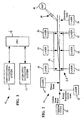
- FIG. 1 is a block diagram showing a conventional navigation system, a set of atom optic instruments and a central processing unit that may be included in the invention;
- FIG. 2 shows the basic structure of an atom optic interferometer that may be included in the set of atom optic instruments of FIG.1 ;
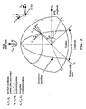
- FIG. 3 shows coordinate systems that may be used for inertial navigation
- FIG. 4 is a functional block diagram showing integration of measurements output from an atom optic instrument with a conventional inertial sensing instruments.
- the present invention is directed to an inertial navigation system 10 in which highly accurate inertial sensors, such as an atom optic instruments 12 are used to provide periodic corrections to a conventional navigation system 14 to provide a continuously operating navigation system having improved accuracy.
- highly accurate inertial sensors such as an atom optic instruments 12 are used to provide periodic corrections to a conventional navigation system 14 to provide a continuously operating navigation system having improved accuracy.
- the atom optic instruments 12 provides periodic, high accuracy inertial measurements to a central processing unit (CPU) 16.
- the CPU 16 also receives navigation information from the conventional navigation system 14.
- the CPU processes signals received from the atom optic instruments 12 and from the conventional navigation system 14 in a Kalman filter to provide a correction to data received from the conventional navigation system 14.
- Atom optic instruments are disclosed in U. S. Patent Nos. 5,274,232, issued December 28, 1993 to Chu et al. and 4,992,656 issued February 12, 1991 to Clauser .
- an atom optic instrument typically includes an evacuated chamber having a plurality of windows. Cooling laser beams are admitted into the chamber through a first group of the windows. The cooling laser beams converge on a target region within the cell and are included in a laser cooling system. As is known in the art a laser cooling system reduces the velocity, and hence the temperature of an atom, by reducing its momentum as the atom absorbs photons in Raman transitions. The cooling laser beams cooperate with a magnetic field to trap atoms, typically Cesium atoms, within the target region for a time of sufficient duration to permit measurements to be made.
- FIG. 2 illustrates an atom optic interferometer 18 that may be included in the set of atom optic instruments 12.
- the invention should not be understood to be limited to any particular high accuracy navigation system and should not be understood to be limited to the specific atom optic interferometer 18 structure shown in FIG. 2 .
- a Cesium oven 20 produces a beam of Cesium atoms that is collimated by two 1 mm diameter apertures (not shown) and then cooled using laser cooling techniques.
- atoms enter a magnetically shielded case 25 that encloses an interrogation region 26.
- Magnetic shielding may be provided by passing electric current through a pair of conducting coils (not shown).
- three pairs of counterpropagating laser beams are used to drive additional Raman transitions.
- the laser beams are oriented to be perpendicular to the atomic beam in a horizontal plane and are provided by lasers 28-33.
- the Cesium atoms enter the interrogation region 26 in the
- a first set of ⁇ /2 Raman pulses from the lasers 28 and 31 puts most of the Cesium atoms in a superposition of the
- This recoil momentum corresponds to a 7 mm/s velocity transverse to the initial velocity of the Cesium atoms, which causes these atoms to separate from atoms remaining in their initial states upon entering the interrogation region as the atoms continue their trajectories.
- the wave packets corresponding to the two atomic states separate by about 23 ⁇ m.
- the atoms pass through a pair of ⁇ Raman beams provided by the lasers 29 and 32, which interact with the Cesium atom states and exchange the two ground states and momenta, which reverses the direction of the atoms that were deflected by the ⁇ /2 Raman beam.
- the atom beams then combine after traveling another meter where a second pair of ⁇ /2 Raman pulses overlaps the two wave packets.
- a lens system 36 focuses the fluorescence resulting from this transition onto a photomultiplier tube, which produces a corresponding electrical signal.
- Dividing the input beam of Cesium atoms into two beams that are subsequently combined as described above produces a Mach-Zehnder interferometer, which is well-known in both bulk optics and fiber optics. Rotation of the atom optic interferometer about an axis perpendicular to the plane defined by the two paths followed by the wave packets produces phase shift between the wave packets in accordance with the Sagnac effect.
- the prior art is replete with examples of ring laser and fiber optic sensors that use the Sagnac effect to measure rotations.
- FIG. 3 shows a navigation coordinate system having orthogonal axes X N , Y N , Z N that are transported with a vehicle relative to the earth where X N , Y N are local-level at the wander angle ⁇ relative to the east and north geodetic axes and Z N is along the local vertical fixed in an object such as an aircraft or a missile.
- FIG. 3 also shows an earth-fixed coordinate system having orthogonal axes X E , Y E , Z E that are fixed relative to the earth.
- An inertial coordinate system has orthogonal axes X I , Y I , Z I that are fixed in inertial space.
- Inertial navigation typically involves transforming measurements made in one coordinate system such as the vehicle body coordinate system into one or more of the three coordinate systems shown.
- the atom optic instrument case 25 has an orthogonal reference set of axes denoted [ x C , y C , z C ].
- the origin of this reference frame is the case-fixed reference point referred to above.
- the point of release of the atom cloud during the measurement periods is assumed to be fixed in the atom optic instrument case reference axes and is denoted by the fixed "lever arm.”
- L L xc L yc L zc .
- the vector k is fixed in the case 25 of the atom optic instrument with coordinates [ k xc , k yc , k zc ] for all time indices i.
- the navigation coordinate system maintained by the conventional inertial navigation system can be defined to be coincident with the local East, North and Vertical [E, N, V] axes at the present position (latitude and longitude of the INS with respect to the earth.
- the vertical can be defined to be normal to the ellipsoidal model of the earth.
- the origin of this navigation coordinate system is a point with respect to which the measurements of force by the conventional accelerometers and angular rotation by the conventional gyros are referred. In general this origin will be separated from the case-fixed reference point of the atom optic instrument by a fixed lever arm that can be expressed in the case coordinate axes of the atom optic instrument or in an orthogonal reference set of axes defined by the conventional inertial instruments. These two orthogonal reference coordinate systems will be related to each other by a fixed transformation.
- the transformation between the coordinate axes defined by the INS sensors and the atom optic instrument case 25 is the identity matrix. It is further assumed that the origins of these two coordinate systems are identical such that the position of the reference point of the atom optic instrument will also be the reference point for navigation using the conventional INS measurements.
- the frame of reference for the trajectory of the atom cloud can be the reference navigation coordinates [X N , Y N , Z N ] defined in FIG. 3 above in which the trajectory of the reference point of the atom optic instrument is expressed or the atom optic case coordinate axes [x c ,y c ,z c ].
- the wander angle ⁇ can be set to zero such that the X N axis points east, E and the Y N axis points north, N.
- the trajectories of the atom cloud and the optical facet can be expressed in either reference frame using a transformation N T C between them.
- the transformation N T C is continuously computed by the INS using the difference of the conventional gyro measured angular rates ⁇ g with respect to inertial space measured along case coordinates, and the INS computed angular rate of the navigation coordinates with respect to inertial space, ⁇ Nc expressed in case coordinates.
- FIG. 4 shows how to develop an expression of the atom cloud trajectory in navigation coordinate axes.
- the gravity vector g N is fixed in the navigation coordinate axes along the local vertical axis, Z N except for gravity disturbances with respect to the earth. The gravity disturbance vector is ignored at this point but can be readily introduced into the mechanization later if it is known.
- the variable g N is defined to be the value of gravity along the local vertical at a current position of the vehicle transporting the INS.
- the gravity vector g N is the combination of the acceleration of gravity due to mass attraction and centripetal acceleration due to earth rotation ⁇ with respect to inertial space.
- V C V X V Y V Z
- V C / E V XN t , V YN t , V ZN t
- the relative velocity of the point of release of the atom cloud with respect to the origin (reference point) of the atom optic instrument case 25 with respect to the earth is expressed as a vector cross product of the lever arm between the two points L , and the relative angular rate of the case 25 with respect to the earth ( ⁇ g - ⁇ Nc ). This term is written as L x ( ⁇ g - ⁇ Nc ) as shown in FIG. 4 .
- the initial position of the atom cloud with respect to the earth is obtained from the initial position of the reference point of the atom optic instrument P C/E (0) N with respect to the earth in the navigation coordinate axes plus the lever arm L between the two positions expressed in the navigation coordinate axes.
- P AC / E ⁇ t N P AC / E ⁇ 0 N + T C N 0 ⁇ L C .
- g N represents acceleration with respect to inertial space expressed in the navigation coordinate axes
- a Coriolis correction C N is required to obtain the time derivative of velocity with respect to the earth with respect to the navigation coordinate axes in which the integration takes place.
- V AC / E ⁇ t N ⁇ g N + C N ⁇ d ⁇ + V AC / E ⁇ 0 N .
- the INS provides the navigation solution for the reference point of the atom optic instrument P C/E (t) N from its initial position P C/E (0) N at the start of the measurement period, 2T.
- FIG. 4 A block diagram depicting the information flow for this mechanization is shown in FIG. 4 .
- the means for correction of the high bandwidth conventional navigation solution obtained with conventional inertial instruments is also shown in FIG. 4 .
- the periodic discontinuous measurement of the phase difference provided by the atom optic instrument ⁇ AO Instrument is compared with an estimate of the phase difference computed using the conventional inertial navigation solution measurements ⁇ Estimated .
- the difference of these two measurements is the discrete observation that is processed by a Kalman filter to correct all error states modeled in the Kalman filter.
- These error states pertain to all significant errors in the conventional inertial navigation solution and the conventional inertial instruments and also all significant error states in the atom optic instrument measurements.
- the Kalman filter may provide corrections to the conventional inertial gyro and accelerometer biases, to attitude errors in N T C , to velocity errors, position errors, and other modeled error sources.
Landscapes
- Engineering & Computer Science (AREA)
- Radar, Positioning & Navigation (AREA)
- Remote Sensing (AREA)
- Physics & Mathematics (AREA)
- General Physics & Mathematics (AREA)
- Automation & Control Theory (AREA)
- Navigation (AREA)
Claims (4)
- Verfahren zur Kombination kontinuierlicher Signale, die von einem ersten Trägheitssensor (14) abgegeben werden, mit diskontinuierlichen Signalen, die von einem zweiten Trägheitssensor (12) abgegeben werden, mit den folgenden Schritten:Verwenden des ersten Trägheitssensors (14) zur Erfassung kontinuierlicher Daten bezüglich eines Navigations-Bezugsrahmens, der bezüglich des ersten Trägheitssensors (14) für einen bei der Trägheitsnavigation verwendeten Parameter festgelegt ist;Verarbeiten der kontinuierlichen Daten zur Erzeugung von Schätzwerten des Parameters;Anordnen des zweiten Trägheitssensors (12) derart, dass dieser diskontinuierliche Daten bezüglich eines Gehäuse-Bezugsrahmens erfasst, die den Parameter bezüglich eines Gehäuses (25) anzeigt, der den zweiten Trägheitssensor (12) enthält;Verarbeiten der diskontinuierlichen Daten zur Erzeugung von Messungen des Parameters zu ausgewählten Zeiten; undVerarbeiten der Schätzwerte des Parameters und der Messungen des Parameters zu ausgewählten Zeiten mit einem Kalman-Filter zur Lieferung von Korrekturen der Schätzwerte des Parameters zu den ausgewählten Zeiten.
- Verfahren nach Anspruch 1, das weiterhin den Schritt der Anordnung des zweiten Trägheitssensors (12) derart umfasst, dass dieser eine größere Genauigkeit als der erste Trägheitssensor (14) aufweist.
- Verfahren nach Anspruch 1, das weiterhin die folgenden Schritte umfasst:Bilden des zweiten Trägheitssensors (12) derart, dass dieser ein atomoptisches Instrument (18) umfasst, das zur Ausbildung eines Positionsbezuges im Trägheitsraum unter Verwendung einer Wolke von ultrakalten Atomen angeordnet ist, die sich in einem Gehäuse (25) für eine endliche Zeitperiode bewegen;Gewinnen von Positionsdaten in dem Navigationsrahmen für die Wolke von Atomen als eine Funktion der Zeit;Bestimmen eines Positionsvektors für die Atomwolke in dem Navigations-Bezugsrahmen zu einer Zeit, zu der die Atomwolke in das Gehäuse (25) freigesetzt wird;Bilden eines Skalarproduktes der Positionsdaten in dem Navigationsrahmen oder der Wolke von Atomen als eine Funktion der Zeit.
- Trägheitsnavigationssystem (10) mit:einer Zentralverarbeitungs-Einheit (16);einem ersten Trägheitssensor (14), der zur Lieferung eines kontinuierlichen, einen Parameter anzeigenden Signals an die Zentralverarbeitungs-Einheit (16) angeordnet ist, wobei die Zentralverarbeitungs-Einheit (16) zur Verarbeitung des kontinuierlichen Signals zur Gewinnung von Schätzwerten des Parameters angeordnet ist; undeinem zweiten Trägheitssensor (12), der zur Lieferung eines diskontinuierlichen, den Parameter anzeigenden Signals an die Zentralverarbeitungseinheit (16) angeordnet ist, wobei die Zentralverarbeitungseinheit (16) zur Verarbeitung des diskontinuierlichen Signals zur Gewinnung von Messungen des Parameters zu ausgewählten Zeiten angeordnet ist, wobei die Zentralverarbeitungseinheit (16) weiterhin zur Verarbeitung der Schätzwerte des Parameters und der Messungen des Parameters zu ausgewählten Zeiten mit einem Kalman-Filter angeordnet ist, um Korrekturen der Schätzwerte des Parameters zu den ausgewählten Zeiten zu liefern.
Applications Claiming Priority (2)
| Application Number | Priority Date | Filing Date | Title |
|---|---|---|---|
| US69295105P | 2005-06-22 | 2005-06-22 | |
| PCT/US2006/024368 WO2007002327A1 (en) | 2005-06-22 | 2006-06-21 | Method for combining continuous and discontinuous inertial instrument measurements and inertial navigation system using the same |
Publications (2)
| Publication Number | Publication Date |
|---|---|
| EP1896796A1 EP1896796A1 (de) | 2008-03-12 |
| EP1896796B1 true EP1896796B1 (de) | 2009-05-13 |
Family
ID=37072562
Family Applications (1)
| Application Number | Title | Priority Date | Filing Date |
|---|---|---|---|
| EP06773797A Expired - Lifetime EP1896796B1 (de) | 2005-06-22 | 2006-06-21 | Verfahren zum kombinieren von kontinuierlichen und diskontinuierlichen trägheitsinstrumentmessungen und trägheitsnavigationssystem damit |
Country Status (6)
| Country | Link |
|---|---|
| US (1) | US20210293543A1 (de) |
| EP (1) | EP1896796B1 (de) |
| JP (1) | JP5523702B2 (de) |
| AT (1) | ATE431544T1 (de) |
| DE (1) | DE602006006832D1 (de) |
| WO (1) | WO2007002327A1 (de) |
Cited By (1)
| Publication number | Priority date | Publication date | Assignee | Title |
|---|---|---|---|---|
| CN103256929A (zh) * | 2012-02-17 | 2013-08-21 | 霍尼韦尔国际公司 | 具有原子惯性传感器的常规惯性传感器的误差估计 |
Families Citing this family (17)
| Publication number | Priority date | Publication date | Assignee | Title |
|---|---|---|---|---|
| FR2928725B1 (fr) * | 2008-03-12 | 2010-04-09 | Centre Nat Rech Scient | Capteur interferometrique a atomes froids |
| CN102853832B (zh) * | 2011-06-29 | 2015-07-08 | 财团法人车辆研究测试中心 | 车辆动态惯性感测器学习校正方法及其装置 |
| US9030655B2 (en) * | 2012-06-27 | 2015-05-12 | Honeywell International Inc. | Closed loop atomic inertial sensor |
| US8860933B2 (en) * | 2012-07-12 | 2014-10-14 | Honeywell International Inc. | Multi-axis atomic inertial sensor system |
| US9134450B2 (en) | 2013-01-07 | 2015-09-15 | Muquans | Cold atom gravity gradiometer |
| KR101391764B1 (ko) | 2014-01-29 | 2014-05-07 | 국방과학연구소 | 관성항법장치와 토털스테이션 간의 축 일치 방법 |
| CN105571590B (zh) * | 2014-10-13 | 2018-07-20 | 北京自动化控制设备研究所 | 一种融合补偿方法 |
| WO2019073655A1 (ja) * | 2017-10-10 | 2019-04-18 | 国立大学法人東京工業大学 | マッハ-ツェンダー型原子干渉に基づくジャイロスコープ |
| AU2018348459A1 (en) * | 2017-10-10 | 2020-04-23 | Japan Aviation Electronics Industry, Limited | Atomic interferometric gyroscope |
| US20200318968A1 (en) * | 2017-10-10 | 2020-10-08 | Tokyo Institute Of Technology | Mach-zehnder type atomic interferometric gyroscope |
| CN108007457B (zh) * | 2017-11-22 | 2021-02-19 | 哈尔滨工业大学 | 一种基于细分时间片的监控导航系统异步数据融合方法 |
| JP6713643B2 (ja) | 2018-12-07 | 2020-06-24 | 日本航空電子工業株式会社 | 原子線コリメーション方法、原子線コリメーター、原子干渉計、原子ジャイロスコープ |
| JP7201172B2 (ja) * | 2019-03-12 | 2023-01-10 | 日本航空電子工業株式会社 | 原子干渉計の回折像検出方法、原子干渉計、原子ジャイロスコープ |
| CN114137625B (zh) * | 2021-11-24 | 2023-04-28 | 中国船舶重工集团公司第七0七研究所 | 一种基于两套惯导互观测的海洋垂线偏差测量方法 |
| CN114923485B (zh) * | 2022-06-23 | 2024-06-18 | 清华大学 | 闭环原子干涉惯性测量方法及装置 |
| CN115900693A (zh) * | 2022-09-19 | 2023-04-04 | 鞍钢集团矿业有限公司 | 基于惯性导航的爆破矿岩运动轨迹获取方法和系统 |
| CN116576888B (zh) * | 2023-05-22 | 2026-03-17 | 重庆邮电大学 | 基于大量程自准直仪的mems陀螺仪安装误差校准方法 |
Family Cites Families (7)
| Publication number | Priority date | Publication date | Assignee | Title |
|---|---|---|---|---|
| US4992656A (en) * | 1987-10-26 | 1991-02-12 | Clauser John F | Rotation, acceleration, and gravity sensors using quantum-mechanical matter-wave interferometry with neutral atoms and molecules |
| JPH03188317A (ja) * | 1989-12-19 | 1991-08-16 | Sumitomo Electric Ind Ltd | 方位検出装置 |
| US5274232A (en) * | 1992-04-14 | 1993-12-28 | Board Of Trustees, Leland Stanford Jr. University | Method and apparatus for manipulating atoms, ions or molecules and for measuring physical quantities using stimulated raman transitions |
| JPH06341848A (ja) * | 1993-05-31 | 1994-12-13 | Hitachi Ltd | ナビゲーション装置 |
| JP3367461B2 (ja) * | 1999-04-13 | 2003-01-14 | 日本電気株式会社 | 移動体姿勢角検出装置 |
| US6907347B2 (en) * | 2002-11-21 | 2005-06-14 | Ford Global Technologies, Llc | Systems and method for estimating speed and pitch sensor errors |
| US7248964B2 (en) * | 2003-12-05 | 2007-07-24 | Honeywell International Inc. | System and method for using multiple aiding sensors in a deeply integrated navigation system |
-
2006
- 2006-06-21 WO PCT/US2006/024368 patent/WO2007002327A1/en not_active Ceased
- 2006-06-21 US US12/086,022 patent/US20210293543A1/en not_active Abandoned
- 2006-06-21 AT AT06773797T patent/ATE431544T1/de not_active IP Right Cessation
- 2006-06-21 EP EP06773797A patent/EP1896796B1/de not_active Expired - Lifetime
- 2006-06-21 DE DE602006006832T patent/DE602006006832D1/de not_active Expired - Lifetime
- 2006-06-21 JP JP2008518403A patent/JP5523702B2/ja not_active Expired - Lifetime
Cited By (2)
| Publication number | Priority date | Publication date | Assignee | Title |
|---|---|---|---|---|
| CN103256929A (zh) * | 2012-02-17 | 2013-08-21 | 霍尼韦尔国际公司 | 具有原子惯性传感器的常规惯性传感器的误差估计 |
| EP2629053A3 (de) * | 2012-02-17 | 2014-12-31 | Honeywell International Inc. | Schätzung konventioneller Inertialsensorfehler mit atomaren Inertialsensoren |
Also Published As
| Publication number | Publication date |
|---|---|
| US20210293543A1 (en) | 2021-09-23 |
| WO2007002327A1 (en) | 2007-01-04 |
| JP5523702B2 (ja) | 2014-06-18 |
| DE602006006832D1 (de) | 2009-06-25 |
| ATE431544T1 (de) | 2009-05-15 |
| EP1896796A1 (de) | 2008-03-12 |
| JP2008544284A (ja) | 2008-12-04 |
Similar Documents
| Publication | Publication Date | Title |
|---|---|---|
| US20210293543A1 (en) | Apparatus and Method for Integrating Continuous and Discontinuous Inertial Instrument | |
| EP2629053B1 (de) | Schätzung konventioneller Inertialsensorfehler mit atomaren Inertialsensoren | |
| US9568316B2 (en) | Ring architecture for sequential operation of an atomic gyroscope | |
| Woodman | An introduction to inertial navigation | |
| Weston et al. | Modern inertial navigation technology and its application | |
| EP1642089B1 (de) | Verfahren und vorrichtung zum erhöhen der inertialnavigationsgenauigkeit mittels gemessener und gespeicherter schwerkraftsgradiente | |
| RU2395061C1 (ru) | Способ определения местоположения подвижных объектов и комплексированная навигационная система для его реализации | |
| US8768621B2 (en) | Signal processing module, navigation device with the signal processing module, vehicle provided with a navigation device and method of providing navigation data | |
| EP1604173B1 (de) | Verfahren zur messung der kraftabhängigen empfindlichkeit von gyroskopen | |
| CN106500693A (zh) | 一种基于自适应扩展卡尔曼滤波的ahrs算法 | |
| EP3123209B1 (de) | Absolutvektor-gravimeter und verfahren zur messung eines absoluten schwerkraftvektors | |
| Reddy et al. | Advanced navigation system for aircraft applications | |
| Tennstedt | Concept and evaluation of a hybridization scheme for atom interferometers and inertial measurement units | |
| Smith | Inertial navigation sensors | |
| Huddle | Trends in inertial systems technology for high accuracy AUV navigation | |
| CN121632108A (zh) | 基于多源数据同步融合的航空重磁矢量动态测量方法 | |
| RU2487318C1 (ru) | Бесплатформенная инерциальная курсовертикаль на чувствительных элементах средней точности | |
| Tennstedt et al. | Dedicated calculation strategy for atom interferometry sensors in inertial navigation | |
| JACKSON | Continuous calibration and alignment techniques for an all-attitude inertial platform | |
| Rice et al. | Submarine navigation applications of atom interferometry | |
| Krobka | The concept of accurate equations of errors and estimations of quantum limits of accuracy of strapdown inertial navigation systems based on laser gyros, fiber-optical gyros, and atom interferometers on de Broglie waves | |
| Hosseiniarani et al. | Performance evaluation of quantum accelerometers for space navigation | |
| Barreda Pupo | Characterization of errors and noises in MEMS inertial sensors using Allan variance method | |
| Zorn | GPS-aided all-accelerometer inertial navigation | |
| Tennstedt et al. | Impact of Uncertainties in Atom Interferometry on Strapdown Navigation Solutions |
Legal Events
| Date | Code | Title | Description |
|---|---|---|---|
| PUAI | Public reference made under article 153(3) epc to a published international application that has entered the european phase |
Free format text: ORIGINAL CODE: 0009012 |
|
| 17P | Request for examination filed |
Effective date: 20071224 |
|
| AK | Designated contracting states |
Kind code of ref document: A1 Designated state(s): AT BE BG CH CY CZ DE DK EE ES FI FR GB GR HU IE IS IT LI LT LU LV MC NL PL PT RO SE SI SK TR |
|
| DAX | Request for extension of the european patent (deleted) | ||
| RAP1 | Party data changed (applicant data changed or rights of an application transferred) |
Owner name: NORTHROP GRUMMAN GUIDANCE AND ELECTRONICS COMPANY, |
|
| DAX | Request for extension of the european patent (deleted) | ||
| GRAP | Despatch of communication of intention to grant a patent |
Free format text: ORIGINAL CODE: EPIDOSNIGR1 |
|
| GRAS | Grant fee paid |
Free format text: ORIGINAL CODE: EPIDOSNIGR3 |
|
| GRAA | (expected) grant |
Free format text: ORIGINAL CODE: 0009210 |
|
| AK | Designated contracting states |
Kind code of ref document: B1 Designated state(s): AT BE BG CH CY CZ DE DK EE ES FI FR GB GR HU IE IS IT LI LT LU LV MC NL PL PT RO SE SI SK TR |
|
| REG | Reference to a national code |
Ref country code: GB Ref legal event code: FG4D |
|
| REG | Reference to a national code |
Ref country code: CH Ref legal event code: EP |
|
| REG | Reference to a national code |
Ref country code: IE Ref legal event code: FG4D |
|
| REF | Corresponds to: |
Ref document number: 602006006832 Country of ref document: DE Date of ref document: 20090625 Kind code of ref document: P |
|
| REG | Reference to a national code |
Ref country code: DE Ref legal event code: R096 Ref document number: 602006006832 Country of ref document: DE Effective date: 20090625 |
|
| PG25 | Lapsed in a contracting state [announced via postgrant information from national office to epo] |
Ref country code: LT Free format text: LAPSE BECAUSE OF FAILURE TO SUBMIT A TRANSLATION OF THE DESCRIPTION OR TO PAY THE FEE WITHIN THE PRESCRIBED TIME-LIMIT Effective date: 20090513 Ref country code: AT Free format text: LAPSE BECAUSE OF FAILURE TO SUBMIT A TRANSLATION OF THE DESCRIPTION OR TO PAY THE FEE WITHIN THE PRESCRIBED TIME-LIMIT Effective date: 20090513 Ref country code: FI Free format text: LAPSE BECAUSE OF FAILURE TO SUBMIT A TRANSLATION OF THE DESCRIPTION OR TO PAY THE FEE WITHIN THE PRESCRIBED TIME-LIMIT Effective date: 20090513 Ref country code: ES Free format text: LAPSE BECAUSE OF FAILURE TO SUBMIT A TRANSLATION OF THE DESCRIPTION OR TO PAY THE FEE WITHIN THE PRESCRIBED TIME-LIMIT Effective date: 20090824 Ref country code: PT Free format text: LAPSE BECAUSE OF FAILURE TO SUBMIT A TRANSLATION OF THE DESCRIPTION OR TO PAY THE FEE WITHIN THE PRESCRIBED TIME-LIMIT Effective date: 20090913 |
|
| NLV1 | Nl: lapsed or annulled due to failure to fulfill the requirements of art. 29p and 29m of the patents act | ||
| PG25 | Lapsed in a contracting state [announced via postgrant information from national office to epo] |
Ref country code: IS Free format text: LAPSE BECAUSE OF FAILURE TO SUBMIT A TRANSLATION OF THE DESCRIPTION OR TO PAY THE FEE WITHIN THE PRESCRIBED TIME-LIMIT Effective date: 20090913 Ref country code: LV Free format text: LAPSE BECAUSE OF FAILURE TO SUBMIT A TRANSLATION OF THE DESCRIPTION OR TO PAY THE FEE WITHIN THE PRESCRIBED TIME-LIMIT Effective date: 20090513 Ref country code: SI Free format text: LAPSE BECAUSE OF FAILURE TO SUBMIT A TRANSLATION OF THE DESCRIPTION OR TO PAY THE FEE WITHIN THE PRESCRIBED TIME-LIMIT Effective date: 20090513 Ref country code: SE Free format text: LAPSE BECAUSE OF FAILURE TO SUBMIT A TRANSLATION OF THE DESCRIPTION OR TO PAY THE FEE WITHIN THE PRESCRIBED TIME-LIMIT Effective date: 20090813 Ref country code: NL Free format text: LAPSE BECAUSE OF FAILURE TO SUBMIT A TRANSLATION OF THE DESCRIPTION OR TO PAY THE FEE WITHIN THE PRESCRIBED TIME-LIMIT Effective date: 20090513 Ref country code: PL Free format text: LAPSE BECAUSE OF FAILURE TO SUBMIT A TRANSLATION OF THE DESCRIPTION OR TO PAY THE FEE WITHIN THE PRESCRIBED TIME-LIMIT Effective date: 20090513 |
|
| PG25 | Lapsed in a contracting state [announced via postgrant information from national office to epo] |
Ref country code: DK Free format text: LAPSE BECAUSE OF FAILURE TO SUBMIT A TRANSLATION OF THE DESCRIPTION OR TO PAY THE FEE WITHIN THE PRESCRIBED TIME-LIMIT Effective date: 20090513 Ref country code: CZ Free format text: LAPSE BECAUSE OF FAILURE TO SUBMIT A TRANSLATION OF THE DESCRIPTION OR TO PAY THE FEE WITHIN THE PRESCRIBED TIME-LIMIT Effective date: 20090513 Ref country code: MC Free format text: LAPSE BECAUSE OF NON-PAYMENT OF DUE FEES Effective date: 20090630 Ref country code: EE Free format text: LAPSE BECAUSE OF FAILURE TO SUBMIT A TRANSLATION OF THE DESCRIPTION OR TO PAY THE FEE WITHIN THE PRESCRIBED TIME-LIMIT Effective date: 20090513 |
|
| PG25 | Lapsed in a contracting state [announced via postgrant information from national office to epo] |
Ref country code: SK Free format text: LAPSE BECAUSE OF FAILURE TO SUBMIT A TRANSLATION OF THE DESCRIPTION OR TO PAY THE FEE WITHIN THE PRESCRIBED TIME-LIMIT Effective date: 20090513 Ref country code: BE Free format text: LAPSE BECAUSE OF FAILURE TO SUBMIT A TRANSLATION OF THE DESCRIPTION OR TO PAY THE FEE WITHIN THE PRESCRIBED TIME-LIMIT Effective date: 20090513 |
|
| PLBE | No opposition filed within time limit |
Free format text: ORIGINAL CODE: 0009261 |
|
| STAA | Information on the status of an ep patent application or granted ep patent |
Free format text: STATUS: NO OPPOSITION FILED WITHIN TIME LIMIT |
|
| PG25 | Lapsed in a contracting state [announced via postgrant information from national office to epo] |
Ref country code: BG Free format text: LAPSE BECAUSE OF FAILURE TO SUBMIT A TRANSLATION OF THE DESCRIPTION OR TO PAY THE FEE WITHIN THE PRESCRIBED TIME-LIMIT Effective date: 20090813 |
|
| REG | Reference to a national code |
Ref country code: IE Ref legal event code: MM4A |
|
| 26N | No opposition filed |
Effective date: 20100216 |
|
| PG25 | Lapsed in a contracting state [announced via postgrant information from national office to epo] |
Ref country code: IE Free format text: LAPSE BECAUSE OF NON-PAYMENT OF DUE FEES Effective date: 20090621 |
|
| REG | Reference to a national code |
Ref country code: DE Ref legal event code: R097 Ref document number: 602006006832 Country of ref document: DE Effective date: 20100216 |
|
| PG25 | Lapsed in a contracting state [announced via postgrant information from national office to epo] |
Ref country code: GR Free format text: LAPSE BECAUSE OF FAILURE TO SUBMIT A TRANSLATION OF THE DESCRIPTION OR TO PAY THE FEE WITHIN THE PRESCRIBED TIME-LIMIT Effective date: 20090814 |
|
| REG | Reference to a national code |
Ref country code: CH Ref legal event code: PL |
|
| PG25 | Lapsed in a contracting state [announced via postgrant information from national office to epo] |
Ref country code: RO Free format text: LAPSE BECAUSE OF FAILURE TO SUBMIT A TRANSLATION OF THE DESCRIPTION OR TO PAY THE FEE WITHIN THE PRESCRIBED TIME-LIMIT Effective date: 20090513 |
|
| PG25 | Lapsed in a contracting state [announced via postgrant information from national office to epo] |
Ref country code: IT Free format text: LAPSE BECAUSE OF FAILURE TO SUBMIT A TRANSLATION OF THE DESCRIPTION OR TO PAY THE FEE WITHIN THE PRESCRIBED TIME-LIMIT Effective date: 20090513 Ref country code: CH Free format text: LAPSE BECAUSE OF NON-PAYMENT OF DUE FEES Effective date: 20090630 Ref country code: LI Free format text: LAPSE BECAUSE OF NON-PAYMENT OF DUE FEES Effective date: 20090630 |
|
| PG25 | Lapsed in a contracting state [announced via postgrant information from national office to epo] |
Ref country code: LI Free format text: LAPSE BECAUSE OF NON-PAYMENT OF DUE FEES Effective date: 20100630 Ref country code: CH Free format text: LAPSE BECAUSE OF NON-PAYMENT OF DUE FEES Effective date: 20100630 Ref country code: LU Free format text: LAPSE BECAUSE OF NON-PAYMENT OF DUE FEES Effective date: 20090621 |
|
| PG25 | Lapsed in a contracting state [announced via postgrant information from national office to epo] |
Ref country code: HU Free format text: LAPSE BECAUSE OF FAILURE TO SUBMIT A TRANSLATION OF THE DESCRIPTION OR TO PAY THE FEE WITHIN THE PRESCRIBED TIME-LIMIT Effective date: 20091114 |
|
| PG25 | Lapsed in a contracting state [announced via postgrant information from national office to epo] |
Ref country code: TR Free format text: LAPSE BECAUSE OF FAILURE TO SUBMIT A TRANSLATION OF THE DESCRIPTION OR TO PAY THE FEE WITHIN THE PRESCRIBED TIME-LIMIT Effective date: 20090513 |
|
| PG25 | Lapsed in a contracting state [announced via postgrant information from national office to epo] |
Ref country code: CY Free format text: LAPSE BECAUSE OF FAILURE TO SUBMIT A TRANSLATION OF THE DESCRIPTION OR TO PAY THE FEE WITHIN THE PRESCRIBED TIME-LIMIT Effective date: 20090513 |
|
| REG | Reference to a national code |
Ref country code: FR Ref legal event code: PLFP Year of fee payment: 11 |
|
| REG | Reference to a national code |
Ref country code: FR Ref legal event code: PLFP Year of fee payment: 12 |
|
| REG | Reference to a national code |
Ref country code: FR Ref legal event code: PLFP Year of fee payment: 13 |
|
| P01 | Opt-out of the competence of the unified patent court (upc) registered |
Effective date: 20230607 |
|
| PGFP | Annual fee paid to national office [announced via postgrant information from national office to epo] |
Ref country code: DE Payment date: 20250618 Year of fee payment: 20 |
|
| PGFP | Annual fee paid to national office [announced via postgrant information from national office to epo] |
Ref country code: GB Payment date: 20250618 Year of fee payment: 20 |
|
| PGFP | Annual fee paid to national office [announced via postgrant information from national office to epo] |
Ref country code: FR Payment date: 20250620 Year of fee payment: 20 |
|
| REG | Reference to a national code |
Ref country code: DE Ref legal event code: R071 Ref document number: 602006006832 Country of ref document: DE |
|
| PG25 | Lapsed in a contracting state [announced via postgrant information from national office to epo] |
Ref country code: GB Free format text: LAPSE BECAUSE OF EXPIRATION OF PROTECTION Effective date: 20260620 |
|
| REG | Reference to a national code |
Ref country code: GB Ref legal event code: PE20 Expiry date: 20260620 |