EP1906418A1 - Dispositif de commande avec un dispositif de contrôle - Google Patents
Dispositif de commande avec un dispositif de contrôle Download PDFInfo
- Publication number
- EP1906418A1 EP1906418A1 EP06020449A EP06020449A EP1906418A1 EP 1906418 A1 EP1906418 A1 EP 1906418A1 EP 06020449 A EP06020449 A EP 06020449A EP 06020449 A EP06020449 A EP 06020449A EP 1906418 A1 EP1906418 A1 EP 1906418A1
- Authority
- EP
- European Patent Office
- Prior art keywords
- control device
- actuating
- switching element
- mounting plate
- command device
- Prior art date
- Legal status (The legal status is an assumption and is not a legal conclusion. Google has not performed a legal analysis and makes no representation as to the accuracy of the status listed.)
- Granted
Links
- 238000009434 installation Methods 0.000 claims description 8
- 238000012544 monitoring process Methods 0.000 description 7
- 230000006870 function Effects 0.000 description 6
- 238000012806 monitoring device Methods 0.000 description 3
- 238000003780 insertion Methods 0.000 description 2
- 230000037431 insertion Effects 0.000 description 2
- 238000000926 separation method Methods 0.000 description 2
- 230000000007 visual effect Effects 0.000 description 2
- 230000008878 coupling Effects 0.000 description 1
- 238000010168 coupling process Methods 0.000 description 1
- 238000005859 coupling reaction Methods 0.000 description 1
- 230000001419 dependent effect Effects 0.000 description 1
- 230000008021 deposition Effects 0.000 description 1
- 238000013461 design Methods 0.000 description 1
- 238000001514 detection method Methods 0.000 description 1
- 238000011161 development Methods 0.000 description 1
- 230000018109 developmental process Effects 0.000 description 1
- 238000011156 evaluation Methods 0.000 description 1
- 230000007257 malfunction Effects 0.000 description 1
- 230000007246 mechanism Effects 0.000 description 1
- 230000003287 optical effect Effects 0.000 description 1
- 230000009993 protective function Effects 0.000 description 1
- 238000009420 retrofitting Methods 0.000 description 1
- 230000011664 signaling Effects 0.000 description 1
Images


Classifications
-
- H—ELECTRICITY
- H01—ELECTRIC ELEMENTS
- H01H—ELECTRIC SWITCHES; RELAYS; SELECTORS; EMERGENCY PROTECTIVE DEVICES
- H01H3/00—Mechanisms for operating contacts
- H01H3/02—Operating parts, i.e. for operating driving mechanism by a mechanical force external to the switch
- H01H3/022—Emergency operating parts, e.g. for stop-switch in dangerous conditions
-
- H—ELECTRICITY
- H01—ELECTRIC ELEMENTS
- H01H—ELECTRIC SWITCHES; RELAYS; SELECTORS; EMERGENCY PROTECTIVE DEVICES
- H01H13/00—Switches having rectilinearly-movable operating part or parts adapted for pushing or pulling in one direction only, e.g. push-button switch
- H01H13/50—Switches having rectilinearly-movable operating part or parts adapted for pushing or pulling in one direction only, e.g. push-button switch having a single operating member
- H01H13/503—Stacked switches
Definitions
- the invention relates to a control device with control device, wherein the control device comprises an actuating element and a fastening element, wherein the fastening element is provided for attachment to a first mounting plate and / or to an operating unit mounted on the first mounting plate, wherein the actuating element for actuating one on a second Mounting plate mounted first switching element is provided, wherein the mounted on the first mounting plate operating unit is provided with proper assembly without control device for actuating the first switching element by means of an actuating plunger. Furthermore, the invention relates to a control device for a command device.
- the command device may be a command switch, for example an emergency stop switch, which has a pot-shaped or mushroom-shaped cap as an actuator.
- the cap or actuator is fixedly connected to the actuating tappet, e.g. screwed. If the command device is actuated, the actuating tappet of the command device is brought from the rest position to the actuated position.
- the actuating plunger inevitably interrupts the contacts of at least one NC switching element, so that the associated circuit is interrupted, for example, a connected electrical machine.
- openers and / or closer switching elements can be mounted, which are actuated together via the actuating plunger.
- command device and its control part usually work according to the principle of forced operation or forced opening.
- the switching state of the switching elements can also be interrogated by a monitoring device, for example by coupling in a bit pattern via the closed NC contacts of an NC switching element and continuously checking the received result.
- a monitoring device is, for example, the ASI-F monitoring device from Siemens. This device is also bus-capable, so that in the absence of the expected bit pattern via a bus data technically achievable plant parts can be brought into a safe state.
- the command device is also designed in two parts.
- the separability is required to attach the command device, for example, to a cabinet door, front panel or panel.
- an actuating unit for mounting through a relatively small hole in a cabinet door or the like out and connected by means of a fastening nut or a clamping ring with this.
- the actuating plunger on the actuator usually by means of a snap or screw, be attached.
- the voltage-carrying parts that are used in the switching elements can be safely installed or accommodated within the control cabinet.
- the command device is divided into an actuating unit and a switching unit, which can be installed separately, but must be brought together in a spatially precise manner for optimal operation.
- Out DE 103 48 884 is a command device is known in which a spatial assignment is monitored by a mounted on the actuator transponder and a corresponding reading unit on the device.
- a fuse element for a command device is known, which is a sealable additional part, wherein the sealable additional part is located behind the cabinet door or inside a housing and is unsuitable for a visual or mechanical control.
- the invention has for its object to provide a control device for a command device, which allows a safe and cost-effective manner, a function control of the command device.
- the invention is further based on the finding that transponder-based solutions are quite complex and therefore cost-intensive.
- the object of the invention is achieved with a command device of the type mentioned above, wherein at the proper assembly of the control device by means of the actuating plunger, at least a second switching element is actuated and at the same time the first switching element is actuated by means of the actuating element. Furthermore, the object is achieved by a control device according to claim 10.
- the control device which is provided for use in a command device, an actuating element and a fastening element.
- the operating unit which is often called simply actuator, on a first mounting plate mounted, wherein the fastening element of the control device, here depending on the position of the component to be controlled, on the mounting plate and / or on the attached actuator can be fastened.
- the components of the actuating unit which do not participate in the actuation movement of the actuator.
- the command device has at least one first switching element which is fastened on a second mounting plate.
- This first switching element optionally together with other switching elements forms the second part of the command device.
- the actuator transmits the actuating movement to the actuating tappet.
- the actuating tappet in turn is provided for actuating the first and a second and / or the optionally existing further switching elements.
- the first switching element is actuated permanently by means of the actuating element of the control device.
- the second or optionally existing further switching elements remain operable by the actuating plunger.
- the first switching element is assigned a new function, namely the function control of the installed command device.
- a mounting error of the actuating unit in the first mounting plate or the switching elements on the second mounting plate and an unwanted position of the mounting plates to each other are thus detectable by means of the first switching element.
- malfunctions that occur during use of the command device such as a deposition by shaking, detectable.
- control device can be used in conventional command devices, since an already existing in the command device switching element for position control in conjunction with the control device is used.
- the first switching element controls a circuit connected to the Detection of an error is used. This can be done for example by an optical signal, so that the user can immediately recognize whether the command device is ready for use or not functional.
- the first switching element is provided for opening and closing a control circuit, so that a multiple application is possible.
- control device for detecting the relative position of at least the second switching element to the operating unit, the function control of the command device and / or for installation control of the command device is provided.
- the control extends to the installation phase and the use phase of the command device.
- positions of components that are not part of the control device verifiable. This guarantees the fitter and the user optimal safety conditions.
- control device is designed in two parts, wherein a first part is a first fastening part and a second part is a second fastening part.
- the operating depth of the control device is variable, which, for example, the use in differently sized control devices is possible, or the dimensions of the housing can be taken into account by the distances of the switching elements of the actuator is variable.
- the first and / or the second mounting plate are each fastened to a first or second housing part or each form at least a first and / or a second housing part.
- it makes sense to install the command device directly into the housing, which saves components and material.
- it is with more complex devices makes sense to install the command device by means of at least one mounting plate, so that the housing choice remains flexible.
- FIG 1 and FIG 2 show an installed emergency stop switch 1 with a control device 9, wherein the emergency stop switch 1 is actuated in FIG 1 unactuated and in FIG.
- the control device 9 which has an actuating element 16 and a fastening element 17.
- the actuator 16 holds the switching element slider 11 in the actuated position.
- the associated first switching element 6 is thus provided for function or position control and indicates a proper mounting of the emergency stop switch 1 on.
- the actuating plunger 10 is connected to the actuator 2 directly, for example via a screw, so that via the actuator 2, a second Switching element 8 and a third switching element 7 via the switching element slide 13, 12 are actuated.
- the actuating tappet 10 is also provided for operating the switching element slider 11 of the first switching element 6, the switching state of the first switching element 6 is not changed during the actuating operation.
- the switching elements 6, 8, 7 are snapped or screwed in the lower housing part 4.
- the actuation of the switching element 6 by the actuator 16 of the control device 9 is also given only if a proper mounting of the switching units, which are usually installed as a block, the operating unit and the housing plates 4, 5 are present.
- the first housing part is designed as a housing upper part 5.
- the second housing part is designed as a lower housing part 4. It makes sense that the control device 9 is attached by means of the fastening element 17 on the guide 18, which belong to the non-movable elements of the emergency stop switch 1.
- the actuating unit is fastened to the upper housing part 5 by means of a fastening part 3, such as a ring nut.
- control device 9 may be part of the actuating device, the actuator 2, the fastening part 3, the upper housing part 5 or a separate part.
- the control device 9 is connected in accordance with the respective components mentioned and does not affect the positive actuation movement of the switching element slide 12, 13.
- the embodiment represents a particularly reliable and economical solution, since it is mechanical and manages without monitoring by an evaluation. Furthermore, a corresponding control device in other command devices, such as in push buttons, selectors or similar switches applicable. Furthermore, it is up to the user whether he wants to work with normally closed or normally open switching elements or a combination of both. This applies both to the first switching element 6, as well as for the second and third switching element 7,8.
- the control circuit which is switched by the first switching element 6 can also be used very variably.
- the corresponding signal can be implemented as desired in terms of tax, it being possible to use acoustic and / or visual alarms or even to shut down the system.
- a message to a control center is also easy to implement by means of the control circuit.
- a mechanical orientation or security against incorrect assembly of the modular control device or its installation can be used within a housing.
- FIG 3 shows the emergency stop switch 1 of FIG 1 in an assembled state.
- the actuating unit and the switching elements 6, 8, 7 are already installed on the upper housing part 5 or on the lower housing part 4. It can be seen that the proper installation, which also includes the proper connection of the housing parts 4, 5, the necessary spatial association between actuator unit and the switching elements 7, 8, 6 entails.
- control device 9 and the switching point of the first switching element 6 are tuned so that the signal of the first switching element 6 is generated before the actuator has moved so far from the switching elements 7, 8, that they no longer properly in an emergency, for example would be pressing.
- the signal of the mechanical switching element 6 can easily be processed by conventional controls, as they are common in simple machines or equipment.
- the first switching element 6 can be connected to other contacts of the controller as desired in parallel or in series to initiate the necessary measures (for example, stop, alarm) in the case of signaling.
- other types of mechanical contacts such as micro-switches
- the upper housing part 5 which is designed for example as a cabinet door and carries a plurality of command devices, all or more actuators monitored with a control device 9 and the associated monitoring switching element, thus ensuring that even with unilateral opening of the cabinet door an incorrect assignment of actuator units and the associated switching elements is detected.
- the circuit is reliably interrupted and remains interrupted if a positively-opening switching element 6 is used.
- the spatial separation is detectable, but also an incorrect or changed assignment of the switching elements to the associated operating units can be reconstructed, which would be detectable, for example, a warped cabinet door.
- control device 9 is provided as a separate part to keep the actuator unit in the event of unwanted detachment of the upper housing part 5 at least in the upper housing part 5, although the proper position is no longer given.
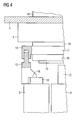
- FIG 4 shows a two-part running control device that can replace the control device 9 of the emergency stop switch 1 of FIG 1.
- the control device consists of two parts, wherein a first fastening part 14, the fastening element 17 and a second fastening part 15 has the actuating element 16. Both parts can be pushed into each other, with different connections for the two-part solution are conceivable.
- the first fastening part 14 and the second fastening part 15 are mutually adjustable, for example by an adjusting screw, which is not shown, wherein the distance of the two parts of the triggering time of the first switching element 6 in the event of detachment of the operating unit can be fixed. It is also conceivable that by a flexible length adjustment, the switching elements 6,7,8 can take a different operational relative position to the operating unit.
- a self-adjustment of the first and second fastening part 14, 15 to each other is provided.
- a latch provided with appropriate force during installation to determine the distance between the two parts.
- the restoring force which acts on the second fastening part 15 by the switching element slider 11, is insufficient to further introduce the second fastening part 15 into the first fastening part 14.
- other fastening mechanisms that allow insertion of the second fastening part 15 into the first fastening part 14, but prevent the removal of the first fastening part 14 from the second fastening part 15 after insertion, for example in connection with barbs.
- the invention relates to a control device with control device, wherein the control device comprises an actuating element and a fastening element.
- the command device is designed in two parts and has an actuating unit and switching elements. The required spatial allocation between actuator and switching elements should be monitored in a cost effective and safe way. For this purpose, with proper assembly of the control device by means of an actuator at least a second switching element operable and simultaneously actuates a first switching element by means of the actuating element of the control device.
Landscapes
- Switch Cases, Indication, And Locking (AREA)
- Push-Button Switches (AREA)
- Keying Circuit Devices (AREA)
- Power-Operated Mechanisms For Wings (AREA)
- Selective Calling Equipment (AREA)
- Massaging Devices (AREA)
- Vehicle Body Suspensions (AREA)
Priority Applications (6)
| Application Number | Priority Date | Filing Date | Title |
|---|---|---|---|
| ES06020449T ES2354826T3 (es) | 2006-09-28 | 2006-09-28 | Aparato de mando con dispositivo de control. |
| AT06020449T ATE493744T1 (de) | 2006-09-28 | 2006-09-28 | Befehlsgerät mit kontrollvorrichtung |
| DE502006008615T DE502006008615D1 (de) | 2006-09-28 | 2006-09-28 | Befehlsgerät mit Kontrollvorrichtung |
| EP06020449A EP1906418B1 (fr) | 2006-09-28 | 2006-09-28 | Dispositif de commande avec un dispositif de contrôle |
| CA2604373A CA2604373C (fr) | 2006-09-28 | 2007-09-26 | Unite de commande comportant un appareil de surveillance |
| US11/905,017 US7781687B2 (en) | 2006-09-28 | 2007-09-27 | Control unit with a monitoring apparatus |
Applications Claiming Priority (1)
| Application Number | Priority Date | Filing Date | Title |
|---|---|---|---|
| EP06020449A EP1906418B1 (fr) | 2006-09-28 | 2006-09-28 | Dispositif de commande avec un dispositif de contrôle |
Publications (2)
| Publication Number | Publication Date |
|---|---|
| EP1906418A1 true EP1906418A1 (fr) | 2008-04-02 |
| EP1906418B1 EP1906418B1 (fr) | 2010-12-29 |
Family
ID=37728224
Family Applications (1)
| Application Number | Title | Priority Date | Filing Date |
|---|---|---|---|
| EP06020449A Not-in-force EP1906418B1 (fr) | 2006-09-28 | 2006-09-28 | Dispositif de commande avec un dispositif de contrôle |
Country Status (6)
| Country | Link |
|---|---|
| US (1) | US7781687B2 (fr) |
| EP (1) | EP1906418B1 (fr) |
| AT (1) | ATE493744T1 (fr) |
| CA (1) | CA2604373C (fr) |
| DE (1) | DE502006008615D1 (fr) |
| ES (1) | ES2354826T3 (fr) |
Cited By (2)
| Publication number | Priority date | Publication date | Assignee | Title |
|---|---|---|---|---|
| WO2011163081A1 (fr) * | 2010-06-22 | 2011-12-29 | Schneider Electric USA, Inc. | Bloc de contact à interverrouillage intégré |
| WO2014202654A1 (fr) * | 2013-06-20 | 2014-12-24 | Eaton Electrical Ip Gmbh & Co. Kg | Interrupteur de sécurité actionnable par pression, à fonction de contrôle |
Families Citing this family (5)
| Publication number | Priority date | Publication date | Assignee | Title |
|---|---|---|---|---|
| DE102007056191A1 (de) * | 2007-11-21 | 2009-05-28 | Rafi Gmbh & Co. Kg | Not-Aus-Schaltvorrichtung |
| JP5095691B2 (ja) * | 2008-10-27 | 2012-12-12 | 富士電機機器制御株式会社 | 押しボタンスイッチ |
| USD924822S1 (en) | 2019-01-18 | 2021-07-13 | Eaton Intelligent Power Limited | Push button |
| CN109638573B (zh) * | 2019-01-30 | 2024-12-24 | 捍防(深圳)实业有限公司 | 用电隐患感知插座 |
| US11609130B2 (en) * | 2021-01-19 | 2023-03-21 | Uneo Inc. | Cantilever force sensor |
Citations (7)
| Publication number | Priority date | Publication date | Assignee | Title |
|---|---|---|---|---|
| DE4101493A1 (de) * | 1991-01-19 | 1992-07-23 | Schlegel Georg Gmbh & Co | Elektrischer schalter mit einer kontaktvorrichtung und einem stoessel |
| DE29517718U1 (de) * | 1995-11-08 | 1996-12-05 | Siemens AG, 80333 München | Vorrichtung zur Notabschaltung von elektrischen Betriebsmitteln |
| WO2000060621A1 (fr) * | 1999-04-01 | 2000-10-12 | Abb Ab | Commutateur de protection |
| DE10047998A1 (de) * | 1999-09-27 | 2001-03-29 | Allen Bradley Company L L C | Schaltkontaktmechanismus |
| DE20305818U1 (de) | 2003-04-08 | 2003-06-12 | Pilz GmbH & Co., 73760 Ostfildern | Notausschalter zum sicherheitsgerichteten Abschalten von elektrischen Einrichtungen |
| DE10348884A1 (de) | 2003-10-14 | 2005-05-25 | Pilz Gmbh & Co. Kg | Sicherheitsschalter, insbesondere Not-Aus-Schalter, zum sicheren Abschalten eines gefahrbringenden Gerätes |
| DE102005010661A1 (de) | 2005-03-08 | 2006-09-14 | Siemens Ag | Befehlsschalter, insbesondere NOT-AUS-Schalter |
Family Cites Families (7)
| Publication number | Priority date | Publication date | Assignee | Title |
|---|---|---|---|---|
| US3118026A (en) * | 1960-12-22 | 1964-01-14 | Gen Electric | Push button switch structure |
| US6376785B1 (en) * | 1999-09-27 | 2002-04-23 | Rockwell Automation Technologies, Inc. | Removable latch assembly for an electrical switch |
| US6987235B2 (en) * | 2003-06-06 | 2006-01-17 | Rockwell Automation Technologies, Inc. | Redundant switch having torsional compliance and arc-absorbant thermal mass |
| US7232965B2 (en) * | 2004-03-19 | 2007-06-19 | Square D Company | Linear motion compensator |
| US7309840B1 (en) * | 2005-07-23 | 2007-12-18 | Emily Lo | Emergency stopping safety device of paper shredder |
| EP1801827B1 (fr) * | 2005-12-20 | 2008-08-20 | Siemens Aktiengesellschaft | Dispositif avec un système de commande et un élément de commutation |
| US7488914B2 (en) * | 2006-08-03 | 2009-02-10 | Delta Systems, Inc. | Plunger switch |
-
2006
- 2006-09-28 ES ES06020449T patent/ES2354826T3/es active Active
- 2006-09-28 EP EP06020449A patent/EP1906418B1/fr not_active Not-in-force
- 2006-09-28 AT AT06020449T patent/ATE493744T1/de active
- 2006-09-28 DE DE502006008615T patent/DE502006008615D1/de active Active
-
2007
- 2007-09-26 CA CA2604373A patent/CA2604373C/fr not_active Expired - Fee Related
- 2007-09-27 US US11/905,017 patent/US7781687B2/en not_active Expired - Fee Related
Patent Citations (7)
| Publication number | Priority date | Publication date | Assignee | Title |
|---|---|---|---|---|
| DE4101493A1 (de) * | 1991-01-19 | 1992-07-23 | Schlegel Georg Gmbh & Co | Elektrischer schalter mit einer kontaktvorrichtung und einem stoessel |
| DE29517718U1 (de) * | 1995-11-08 | 1996-12-05 | Siemens AG, 80333 München | Vorrichtung zur Notabschaltung von elektrischen Betriebsmitteln |
| WO2000060621A1 (fr) * | 1999-04-01 | 2000-10-12 | Abb Ab | Commutateur de protection |
| DE10047998A1 (de) * | 1999-09-27 | 2001-03-29 | Allen Bradley Company L L C | Schaltkontaktmechanismus |
| DE20305818U1 (de) | 2003-04-08 | 2003-06-12 | Pilz GmbH & Co., 73760 Ostfildern | Notausschalter zum sicherheitsgerichteten Abschalten von elektrischen Einrichtungen |
| DE10348884A1 (de) | 2003-10-14 | 2005-05-25 | Pilz Gmbh & Co. Kg | Sicherheitsschalter, insbesondere Not-Aus-Schalter, zum sicheren Abschalten eines gefahrbringenden Gerätes |
| DE102005010661A1 (de) | 2005-03-08 | 2006-09-14 | Siemens Ag | Befehlsschalter, insbesondere NOT-AUS-Schalter |
Cited By (3)
| Publication number | Priority date | Publication date | Assignee | Title |
|---|---|---|---|---|
| WO2011163081A1 (fr) * | 2010-06-22 | 2011-12-29 | Schneider Electric USA, Inc. | Bloc de contact à interverrouillage intégré |
| WO2014202654A1 (fr) * | 2013-06-20 | 2014-12-24 | Eaton Electrical Ip Gmbh & Co. Kg | Interrupteur de sécurité actionnable par pression, à fonction de contrôle |
| US9589741B2 (en) | 2013-06-20 | 2017-03-07 | Eaton Electrical Ip Gmbh & Co. Kg | Pressure-actuated safety switch with monitoring function |
Also Published As
| Publication number | Publication date |
|---|---|
| US7781687B2 (en) | 2010-08-24 |
| US20090200145A1 (en) | 2009-08-13 |
| ATE493744T1 (de) | 2011-01-15 |
| ES2354826T3 (es) | 2011-03-18 |
| DE502006008615D1 (de) | 2011-02-10 |
| CA2604373A1 (fr) | 2008-03-28 |
| CA2604373C (fr) | 2012-02-21 |
| EP1906418B1 (fr) | 2010-12-29 |
Similar Documents
| Publication | Publication Date | Title |
|---|---|---|
| EP3011576B1 (fr) | Boutton-poussoir de securite avec dispositif de detection l'assemblage correct | |
| DE2030867B2 (de) | Elektrische Alarmbetatigungs vorrichtung | |
| EP1906418B1 (fr) | Dispositif de commande avec un dispositif de contrôle | |
| EP4080102A1 (fr) | Interrupteur de sécurité à gâchette | |
| EP1856706B1 (fr) | Interrupteur de commande, en particulier interrupteur d'urgence | |
| DE102008055685B4 (de) | Vorrichtung zum Überwachen des Zustandes einer Schutzeinrichtung einer Maschine | |
| EP2704273B1 (fr) | Dispositif de commande et de signalisation destiné à être monté dans l'orifice de montage d'une plaque de montage | |
| EP1964139B1 (fr) | Appareil de commande dote d'une surveillance des elements de commutation | |
| EP2413341B1 (fr) | Capteur de pression pour affichage signalétique mécanique | |
| DE102019216463A1 (de) | Türwächter | |
| EP4361491A1 (fr) | Module de surveillance de porte de protection | |
| EP2704272B1 (fr) | Dispositif de commande et de signalisation destine a etre monte dans l'orifice de montage d'une plaque de montage | |
| EP1460666B1 (fr) | Touche pour des procédés de commutation de sécurité | |
| DE3718339A1 (de) | Schluesselschalter bzw. schluesseltaster | |
| EP2284432B1 (fr) | Dispositif de surveillance d'un état d'un dispositif relevant de la sécurité | |
| DE202012008253U1 (de) | Befehls- und Meldegerät | |
| DE102009008537B3 (de) | Drucktaster | |
| EP2852014B1 (fr) | Appareil de commande et de signalisation doté d'un montage encastré en façade | |
| EP3171380B1 (fr) | Combinaison d'actionneur et dispositif de retenue pour des elements de commutation pour un appareil de communication et de commande | |
| DE102007001768B4 (de) | Sicherheitsschalter | |
| EP0109590A2 (fr) | Dispositif de sécurité de verrouillage de porte | |
| DE4002470C2 (de) | Befehlsgerät zum Einbau zwischen zwei parallelflächigen Gehäuseteilen | |
| EP0133923A1 (fr) | Dispositif d'alarme pour portes et fenêtres | |
| DE202012008252U1 (de) | Befehls- und Meldegerät | |
| EP3092656A1 (fr) | Actionneur comprenant un afficheur signalétique mécanique |
Legal Events
| Date | Code | Title | Description |
|---|---|---|---|
| PUAI | Public reference made under article 153(3) epc to a published international application that has entered the european phase |
Free format text: ORIGINAL CODE: 0009012 |
|
| AK | Designated contracting states |
Kind code of ref document: A1 Designated state(s): AT BE BG CH CY CZ DE DK EE ES FI FR GB GR HU IE IS IT LI LT LU LV MC NL PL PT RO SE SI SK TR |
|
| AX | Request for extension of the european patent |
Extension state: AL BA HR MK YU |
|
| 17P | Request for examination filed |
Effective date: 20080424 |
|
| 17Q | First examination report despatched |
Effective date: 20080604 |
|
| AKX | Designation fees paid |
Designated state(s): AT BE BG CH CY CZ DE DK EE ES FI FR GB GR HU IE IS IT LI LT LU LV MC NL PL PT RO SE SI SK TR |
|
| GRAP | Despatch of communication of intention to grant a patent |
Free format text: ORIGINAL CODE: EPIDOSNIGR1 |
|
| GRAS | Grant fee paid |
Free format text: ORIGINAL CODE: EPIDOSNIGR3 |
|
| GRAA | (expected) grant |
Free format text: ORIGINAL CODE: 0009210 |
|
| AK | Designated contracting states |
Kind code of ref document: B1 Designated state(s): AT BE BG CH CY CZ DE DK EE ES FI FR GB GR HU IE IS IT LI LT LU LV MC NL PL PT RO SE SI SK TR |
|
| REG | Reference to a national code |
Ref country code: GB Ref legal event code: FG4D Free format text: NOT ENGLISH |
|
| REG | Reference to a national code |
Ref country code: CH Ref legal event code: EP |
|
| REG | Reference to a national code |
Ref country code: IE Ref legal event code: FG4D Free format text: LANGUAGE OF EP DOCUMENT: GERMAN |
|
| REF | Corresponds to: |
Ref document number: 502006008615 Country of ref document: DE Date of ref document: 20110210 Kind code of ref document: P |
|
| REG | Reference to a national code |
Ref country code: DE Ref legal event code: R096 Ref document number: 502006008615 Country of ref document: DE Effective date: 20110210 |
|
| REG | Reference to a national code |
Ref country code: ES Ref legal event code: FG2A Effective date: 20110308 |
|
| REG | Reference to a national code |
Ref country code: NL Ref legal event code: VDEP Effective date: 20101229 |
|
| PG25 | Lapsed in a contracting state [announced via postgrant information from national office to epo] |
Ref country code: LT Free format text: LAPSE BECAUSE OF FAILURE TO SUBMIT A TRANSLATION OF THE DESCRIPTION OR TO PAY THE FEE WITHIN THE PRESCRIBED TIME-LIMIT Effective date: 20101229 |
|
| LTIE | Lt: invalidation of european patent or patent extension |
Effective date: 20101229 |
|
| PG25 | Lapsed in a contracting state [announced via postgrant information from national office to epo] |
Ref country code: SE Free format text: LAPSE BECAUSE OF FAILURE TO SUBMIT A TRANSLATION OF THE DESCRIPTION OR TO PAY THE FEE WITHIN THE PRESCRIBED TIME-LIMIT Effective date: 20101229 Ref country code: CY Free format text: LAPSE BECAUSE OF FAILURE TO SUBMIT A TRANSLATION OF THE DESCRIPTION OR TO PAY THE FEE WITHIN THE PRESCRIBED TIME-LIMIT Effective date: 20101229 Ref country code: SI Free format text: LAPSE BECAUSE OF FAILURE TO SUBMIT A TRANSLATION OF THE DESCRIPTION OR TO PAY THE FEE WITHIN THE PRESCRIBED TIME-LIMIT Effective date: 20101229 Ref country code: BG Free format text: LAPSE BECAUSE OF FAILURE TO SUBMIT A TRANSLATION OF THE DESCRIPTION OR TO PAY THE FEE WITHIN THE PRESCRIBED TIME-LIMIT Effective date: 20110329 Ref country code: LV Free format text: LAPSE BECAUSE OF FAILURE TO SUBMIT A TRANSLATION OF THE DESCRIPTION OR TO PAY THE FEE WITHIN THE PRESCRIBED TIME-LIMIT Effective date: 20101229 Ref country code: FI Free format text: LAPSE BECAUSE OF FAILURE TO SUBMIT A TRANSLATION OF THE DESCRIPTION OR TO PAY THE FEE WITHIN THE PRESCRIBED TIME-LIMIT Effective date: 20101229 |
|
| REG | Reference to a national code |
Ref country code: IE Ref legal event code: FD4D |
|
| PG25 | Lapsed in a contracting state [announced via postgrant information from national office to epo] |
Ref country code: PT Free format text: LAPSE BECAUSE OF FAILURE TO SUBMIT A TRANSLATION OF THE DESCRIPTION OR TO PAY THE FEE WITHIN THE PRESCRIBED TIME-LIMIT Effective date: 20110429 Ref country code: CZ Free format text: LAPSE BECAUSE OF FAILURE TO SUBMIT A TRANSLATION OF THE DESCRIPTION OR TO PAY THE FEE WITHIN THE PRESCRIBED TIME-LIMIT Effective date: 20101229 Ref country code: IS Free format text: LAPSE BECAUSE OF FAILURE TO SUBMIT A TRANSLATION OF THE DESCRIPTION OR TO PAY THE FEE WITHIN THE PRESCRIBED TIME-LIMIT Effective date: 20110429 Ref country code: EE Free format text: LAPSE BECAUSE OF FAILURE TO SUBMIT A TRANSLATION OF THE DESCRIPTION OR TO PAY THE FEE WITHIN THE PRESCRIBED TIME-LIMIT Effective date: 20101229 Ref country code: GR Free format text: LAPSE BECAUSE OF FAILURE TO SUBMIT A TRANSLATION OF THE DESCRIPTION OR TO PAY THE FEE WITHIN THE PRESCRIBED TIME-LIMIT Effective date: 20110330 |
|
| PG25 | Lapsed in a contracting state [announced via postgrant information from national office to epo] |
Ref country code: NL Free format text: LAPSE BECAUSE OF FAILURE TO SUBMIT A TRANSLATION OF THE DESCRIPTION OR TO PAY THE FEE WITHIN THE PRESCRIBED TIME-LIMIT Effective date: 20101229 Ref country code: SK Free format text: LAPSE BECAUSE OF FAILURE TO SUBMIT A TRANSLATION OF THE DESCRIPTION OR TO PAY THE FEE WITHIN THE PRESCRIBED TIME-LIMIT Effective date: 20101229 Ref country code: RO Free format text: LAPSE BECAUSE OF FAILURE TO SUBMIT A TRANSLATION OF THE DESCRIPTION OR TO PAY THE FEE WITHIN THE PRESCRIBED TIME-LIMIT Effective date: 20101229 Ref country code: PL Free format text: LAPSE BECAUSE OF FAILURE TO SUBMIT A TRANSLATION OF THE DESCRIPTION OR TO PAY THE FEE WITHIN THE PRESCRIBED TIME-LIMIT Effective date: 20101229 |
|
| PG25 | Lapsed in a contracting state [announced via postgrant information from national office to epo] |
Ref country code: DK Free format text: LAPSE BECAUSE OF FAILURE TO SUBMIT A TRANSLATION OF THE DESCRIPTION OR TO PAY THE FEE WITHIN THE PRESCRIBED TIME-LIMIT Effective date: 20101229 Ref country code: IE Free format text: LAPSE BECAUSE OF FAILURE TO SUBMIT A TRANSLATION OF THE DESCRIPTION OR TO PAY THE FEE WITHIN THE PRESCRIBED TIME-LIMIT Effective date: 20101229 |
|
| PLBE | No opposition filed within time limit |
Free format text: ORIGINAL CODE: 0009261 |
|
| STAA | Information on the status of an ep patent application or granted ep patent |
Free format text: STATUS: NO OPPOSITION FILED WITHIN TIME LIMIT |
|
| 26N | No opposition filed |
Effective date: 20110930 |
|
| REG | Reference to a national code |
Ref country code: DE Ref legal event code: R097 Ref document number: 502006008615 Country of ref document: DE Effective date: 20110930 |
|
| BERE | Be: lapsed |
Owner name: SIEMENS A.G. Effective date: 20110930 |
|
| PG25 | Lapsed in a contracting state [announced via postgrant information from national office to epo] |
Ref country code: MC Free format text: LAPSE BECAUSE OF NON-PAYMENT OF DUE FEES Effective date: 20110930 |
|
| REG | Reference to a national code |
Ref country code: CH Ref legal event code: PL |
|
| GBPC | Gb: european patent ceased through non-payment of renewal fee |
Effective date: 20110928 |
|
| PG25 | Lapsed in a contracting state [announced via postgrant information from national office to epo] |
Ref country code: BE Free format text: LAPSE BECAUSE OF NON-PAYMENT OF DUE FEES Effective date: 20110930 |
|
| PG25 | Lapsed in a contracting state [announced via postgrant information from national office to epo] |
Ref country code: CH Free format text: LAPSE BECAUSE OF NON-PAYMENT OF DUE FEES Effective date: 20110930 Ref country code: LI Free format text: LAPSE BECAUSE OF NON-PAYMENT OF DUE FEES Effective date: 20110930 |
|
| PG25 | Lapsed in a contracting state [announced via postgrant information from national office to epo] |
Ref country code: GB Free format text: LAPSE BECAUSE OF NON-PAYMENT OF DUE FEES Effective date: 20110928 |
|
| REG | Reference to a national code |
Ref country code: AT Ref legal event code: MM01 Ref document number: 493744 Country of ref document: AT Kind code of ref document: T Effective date: 20110928 |
|
| PG25 | Lapsed in a contracting state [announced via postgrant information from national office to epo] |
Ref country code: AT Free format text: LAPSE BECAUSE OF NON-PAYMENT OF DUE FEES Effective date: 20110928 |
|
| PG25 | Lapsed in a contracting state [announced via postgrant information from national office to epo] |
Ref country code: LU Free format text: LAPSE BECAUSE OF NON-PAYMENT OF DUE FEES Effective date: 20110928 |
|
| PG25 | Lapsed in a contracting state [announced via postgrant information from national office to epo] |
Ref country code: TR Free format text: LAPSE BECAUSE OF FAILURE TO SUBMIT A TRANSLATION OF THE DESCRIPTION OR TO PAY THE FEE WITHIN THE PRESCRIBED TIME-LIMIT Effective date: 20101229 |
|
| PG25 | Lapsed in a contracting state [announced via postgrant information from national office to epo] |
Ref country code: HU Free format text: LAPSE BECAUSE OF FAILURE TO SUBMIT A TRANSLATION OF THE DESCRIPTION OR TO PAY THE FEE WITHIN THE PRESCRIBED TIME-LIMIT Effective date: 20101229 |
|
| REG | Reference to a national code |
Ref country code: FR Ref legal event code: PLFP Year of fee payment: 11 |
|
| PGFP | Annual fee paid to national office [announced via postgrant information from national office to epo] |
Ref country code: FR Payment date: 20160914 Year of fee payment: 11 |
|
| PGFP | Annual fee paid to national office [announced via postgrant information from national office to epo] |
Ref country code: DE Payment date: 20161121 Year of fee payment: 11 |
|
| PGFP | Annual fee paid to national office [announced via postgrant information from national office to epo] |
Ref country code: IT Payment date: 20160928 Year of fee payment: 11 Ref country code: ES Payment date: 20161026 Year of fee payment: 11 |
|
| REG | Reference to a national code |
Ref country code: DE Ref legal event code: R119 Ref document number: 502006008615 Country of ref document: DE |
|
| REG | Reference to a national code |
Ref country code: FR Ref legal event code: ST Effective date: 20180531 |
|
| PG25 | Lapsed in a contracting state [announced via postgrant information from national office to epo] |
Ref country code: DE Free format text: LAPSE BECAUSE OF NON-PAYMENT OF DUE FEES Effective date: 20180404 |
|
| PG25 | Lapsed in a contracting state [announced via postgrant information from national office to epo] |
Ref country code: IT Free format text: LAPSE BECAUSE OF NON-PAYMENT OF DUE FEES Effective date: 20170928 Ref country code: FR Free format text: LAPSE BECAUSE OF NON-PAYMENT OF DUE FEES Effective date: 20171002 |
|
| REG | Reference to a national code |
Ref country code: ES Ref legal event code: FD2A Effective date: 20181017 |
|
| PG25 | Lapsed in a contracting state [announced via postgrant information from national office to epo] |
Ref country code: ES Free format text: LAPSE BECAUSE OF NON-PAYMENT OF DUE FEES Effective date: 20170929 |