EP1914089B1 - Lenkrolle mit hochfestem Achsträger - Google Patents
Lenkrolle mit hochfestem Achsträger Download PDFInfo
- Publication number
- EP1914089B1 EP1914089B1 EP07118122A EP07118122A EP1914089B1 EP 1914089 B1 EP1914089 B1 EP 1914089B1 EP 07118122 A EP07118122 A EP 07118122A EP 07118122 A EP07118122 A EP 07118122A EP 1914089 B1 EP1914089 B1 EP 1914089B1
- Authority
- EP
- European Patent Office
- Prior art keywords
- housing
- axle
- caster
- axle carrier
- opening
- Prior art date
- Legal status (The legal status is an assumption and is not a legal conclusion. Google has not performed a legal analysis and makes no representation as to the accuracy of the status listed.)
- Active
Links
Images
Classifications
-
- B—PERFORMING OPERATIONS; TRANSPORTING
- B60—VEHICLES IN GENERAL
- B60B—VEHICLE WHEELS; CASTORS; AXLES FOR WHEELS OR CASTORS; INCREASING WHEEL ADHESION
- B60B33/00—Castors in general ; Anti-clogging castors
- B60B33/0028—Construction of wheels; methods of assembling on axle
-
- B—PERFORMING OPERATIONS; TRANSPORTING
- B60—VEHICLES IN GENERAL
- B60B—VEHICLE WHEELS; CASTORS; AXLES FOR WHEELS OR CASTORS; INCREASING WHEEL ADHESION
- B60B33/00—Castors in general ; Anti-clogging castors
- B60B33/0002—Castors in general ; Anti-clogging castors assembling to the object, e.g. furniture
- B60B33/0005—Castors in general ; Anti-clogging castors assembling to the object, e.g. furniture characterised by mounting method
- B60B33/001—Castors in general ; Anti-clogging castors assembling to the object, e.g. furniture characterised by mounting method by snapping, clicking or latching in
-
- B—PERFORMING OPERATIONS; TRANSPORTING
- B60—VEHICLES IN GENERAL
- B60B—VEHICLE WHEELS; CASTORS; AXLES FOR WHEELS OR CASTORS; INCREASING WHEEL ADHESION
- B60B33/00—Castors in general ; Anti-clogging castors
- B60B33/0002—Castors in general ; Anti-clogging castors assembling to the object, e.g. furniture
- B60B33/0015—Castors in general ; Anti-clogging castors assembling to the object, e.g. furniture characterised by adaptations made to castor
- B60B33/0021—Castors in general ; Anti-clogging castors assembling to the object, e.g. furniture characterised by adaptations made to castor in the form of a mounting pin
-
- B—PERFORMING OPERATIONS; TRANSPORTING
- B60—VEHICLES IN GENERAL
- B60B—VEHICLE WHEELS; CASTORS; AXLES FOR WHEELS OR CASTORS; INCREASING WHEEL ADHESION
- B60B33/00—Castors in general ; Anti-clogging castors
- B60B33/0036—Castors in general ; Anti-clogging castors characterised by type of wheels
- B60B33/0042—Double or twin wheels
-
- B—PERFORMING OPERATIONS; TRANSPORTING
- B60—VEHICLES IN GENERAL
- B60B—VEHICLE WHEELS; CASTORS; AXLES FOR WHEELS OR CASTORS; INCREASING WHEEL ADHESION
- B60B33/00—Castors in general ; Anti-clogging castors
- B60B33/0047—Castors in general ; Anti-clogging castors characterised by details of the rolling axle
- B60B33/0049—Castors in general ; Anti-clogging castors characterised by details of the rolling axle the rolling axle being horizontal
-
- B—PERFORMING OPERATIONS; TRANSPORTING
- B60—VEHICLES IN GENERAL
- B60B—VEHICLE WHEELS; CASTORS; AXLES FOR WHEELS OR CASTORS; INCREASING WHEEL ADHESION
- B60B33/00—Castors in general ; Anti-clogging castors
- B60B33/0047—Castors in general ; Anti-clogging castors characterised by details of the rolling axle
- B60B33/0057—Castors in general ; Anti-clogging castors characterised by details of the rolling axle the rolling axle being offset from swivel axis
-
- B—PERFORMING OPERATIONS; TRANSPORTING
- B60—VEHICLES IN GENERAL
- B60B—VEHICLE WHEELS; CASTORS; AXLES FOR WHEELS OR CASTORS; INCREASING WHEEL ADHESION
- B60B33/00—Castors in general ; Anti-clogging castors
- B60B33/006—Castors in general ; Anti-clogging castors characterised by details of the swivel mechanism
- B60B33/0065—Castors in general ; Anti-clogging castors characterised by details of the swivel mechanism characterised by details of the swivel axis
- B60B33/0068—Castors in general ; Anti-clogging castors characterised by details of the swivel mechanism characterised by details of the swivel axis the swivel axis being vertical
-
- B—PERFORMING OPERATIONS; TRANSPORTING
- B60—VEHICLES IN GENERAL
- B60B—VEHICLE WHEELS; CASTORS; AXLES FOR WHEELS OR CASTORS; INCREASING WHEEL ADHESION
- B60B33/00—Castors in general ; Anti-clogging castors
- B60B33/006—Castors in general ; Anti-clogging castors characterised by details of the swivel mechanism
- B60B33/0065—Castors in general ; Anti-clogging castors characterised by details of the swivel mechanism characterised by details of the swivel axis
- B60B33/0073—Castors in general ; Anti-clogging castors characterised by details of the swivel mechanism characterised by details of the swivel axis the swivel axis being symmetrical to wheel or wheels
Definitions
- the invention relates to a castor, in particular a free-running castor, with twin wheels, with a housing having a substantially vertically oriented upper-side pin opening for receiving a pivot for connecting the roller with a piece of furniture or other object, and with a housing transversely to the pin opening passing, the wheels bearing axle bolt, wherein in the housing an axle with an opening for the axle bolt is arranged and wherein the axle carrier consists of a material having a higher strength than that of the housing.
- the axle In conventional roles, the axle is pressed directly into the roller housing. Since large forces are absorbed by the housing in the area of the axle bolt, for example impacts when driving over a threshold or hard seating of the furniture on a roller, the axle receptacle of the housing can be quickly deformed or damaged. For this reason, a high-quality, but also expensive plastic is used for the production of the housing.
- a generic role is from the WO2006 / 117128 A1 known.
- the axle is slidably disposed in the housing to allow a braked and an unrestrained position of the wheels.
- Other roles with a sliding axle, but not made of a material with higher strength than that of the housing, are from the DE 27 35 343 A1 , of the US 2005/108851 A1 , of the DE 299 21 992 U1 as well as the DE 76 38 720 U1 known.
- the object of the present invention is to develop an unchecked role of the type mentioned, despite high mechanical strength in the area of the axle allows cost-effective production.
- the invention is based primarily on the idea that the largest loads of the role occur in the area of the axle, but that far away parts of the housing are far less burdened and thus basically can consist of a less solid, but more cost-effective material. According to the invention it is therefore provided that the existing of a material with a higher strength than that of the housing axle carrier is pressed into the housing, glued or welded thereto.
- the axle carrier requires as a separate component substantially less material than the rest of the housing, so that for the axle a higher quality material can be used as for the housing.
- the required strength of the axle receiving area is thus achieved at a lower cost than if the entire housing were made of the stronger material.
- the axle can be completely enclosed by the remaining housing material, example, by appropriate arrangement of the axle carrier in an injection mold for the housing.
- the housing has an outwardly open, shaft-shaped axle carrier opening for receiving the axle carrier. The housing and the axle can then be made independently and assembled at any time.
- both the housing and the axle are made of a plastic material, the housing, for example, a polypropylene and the axle of a polyamide.
- the axle can also consist of a metal, preferably of a zinc or scarfrnetallleg ist.
- the axle carrier can have any desired cross-sectional shape, for example a rectangular or a round, but preferably has a substantially rectangular cross-section with two integrally formed ribs arranged transversely to the passage opening of the axle bolt.
- a levering of the housing under extreme load can be avoided if the axle support in an alternative embodiment has a substantially dumbbell-shaped cross-section, wherein the respective T-shaped end portions in corresponding undercuts of the axle support.
- the axle bolt is pressed into the passage opening of the axle carrier, wherein it can have a knurling or similar profiling on its recorded in the axle support lot to achieve a positive and a positive fit.
- a particularly secure fit of the wheels on the axle is given when the axle is provided on both sides of the housing with two spaced undercuts, with which beads on the inside of the tubular hub of the wheels are engaged.
- the hubs of the wheels can extend axially into the region of the wall portions delimiting the axle carrier opening.
- axle carrier opening is preferably arranged offset in the bottom side of the housing laterally relative to the pin opening.
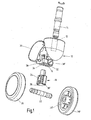
- the roller shown in the drawing consists essentially of a housing 10 with a pin opening 12 for receiving a pivot pin 14, by means of which the roller is rotatably mounted on a piece of furniture or the like, and with an Achsangeö réelle 16 for receiving an axle beam 18, from a pivot pin 22, which is pressed into a passage opening 24 of the axle carrier 18 and aligned transversely to the Achsangeö réelle 16, and two wheels 26, 26 'with tubular hubs 28, 28', which are plugged onto the free ends of the axle pin 22 and on this rotate.
- the wheels consist of a wheel body with sprayed running surfaces made of a material adapted to the purpose, such as a soft material for use on hard floors or a hard material for use on carpets o. The like.
- An arcuate roof 30 of the housing 10 covers the top of the Wheels 26, 26 '.
- the housing 10 In the region of the axle carrier opening 16, the housing 10 has recesses 32, which are penetrated by the axle carrier 18 and guide it. Transverse thereto, the housing has grooves 34 into which ribs 36, 36 'integrally formed on the axle carrier 18 engage. This measure also serves to better guide the axle beam 18 and increases the load capacity of the arrangement.
- At the lower end of the Achsismeö réelle 16 are two projections 38, 38 'laterally from the housing wall. These projections 38, 38 'form a lateral cover for the hubs and the overlying housing portion, so that an entry of dirt is prevented there. At the same time, they reinforce the housing 10 in the region of the axle carrier opening 16 such that the housing portion accommodating the axle carrier 18 can be made comparatively narrow.
- the hubs 28, 28 'of the wheels can be made particularly long and guided into the area of the recesses 32, whereby they can have a comparatively large receiving depth for the axle pin 22, which increases the stability and load-bearing capacity of the roller.
- the use of material for the production of the housing 10 can be significantly reduced while maintaining the required load capacity.
- the axle support 18 When mounting the roller, the axle support 18 is first pressed into the Achsangeö réelle 16 or inserted and fixed, so that the passage opening 24 is released for the axle 22 and between the axle 22 and the projections 38, 38 'sufficient clearance for the hubs of the wheels is available. Then the axle pin 22 is pressed centered in the passage opening 24. Finally, the wheels 26, 26 'with their tubular hubs 28, 28' pushed onto the axle bolt 22, wherein they engage with beads in undercuts or grooves in the axle 22. The insertion of the pivot pin 14 in the pin opening 12 can be done before or after the assembly of the axle beam, the axle bolt and the wheels.
- the invention relates to a castor, in particular free-running castor, with twin wheels 26, 26 ', with a housing 10 with a substantially vertically oriented, top-side spigot 12 for receiving a pivot pin 14 for connecting the role with a piece of furniture or a
- a castor in particular free-running castor, with twin wheels 26, 26 ', with a housing 10 with a substantially vertically oriented, top-side spigot 12 for receiving a pivot pin 14 for connecting the role with a piece of furniture or a
- an axle support 18 with a passage opening 24th arranged for the axle 22 is, wherein the axle support 18 is made of a material having a higher strength than that of the housing 10.
Landscapes
- Engineering & Computer Science (AREA)
- Mechanical Engineering (AREA)
- Handcart (AREA)
- Legs For Furniture In General (AREA)
- Electric Suction Cleaners (AREA)
- Transition And Organic Metals Composition Catalysts For Addition Polymerization (AREA)
Description
- Die Erfindung betrifft eine Lenkrolle, insbesondere eine freilaufende Lenkrolle, mit Zwillingsrädem, mit einem Gehäuse mit einer im Wesentlichen vertikal ausgerichteten, oberseitigen Zapfenöffnung zur Aufnahme eines Drehzapfens zur Verbindung der Rolle mit einem Möbelstück oder einem anderen Gegenstand, und mit einem das Gehäuse quer zur Zapfenöffnung durchsetzenden, die Räder tragenden Achsbolzen, wobei in dem Gehäuse ein Achsträger mit einer Durchtrittsöffnung für den Achsbolzen angeordnet ist und wobei der Achsträger aus einem Material mit einer höheren Festigkeit als die des Gehäuses besteht.
- Bei herkömmlichen Rollen ist der Achsbolzen direkt in das Rollengehäuse eingepresst. Da im Bereich des Achsbolzens große Kräfte von dem Gehäuse aufgenommen werden, beispielsweise Stöße beim Überfahren einer Schwelle oder beim harten Aufsetzen des Möbelstücks auf eine Rolle, kann die Achsaufnahme des Gehäuses schnell deformiert oder beschädigt werden. Aus diesem Grund wird ein hochwertiger, damit jedoch auch teurer Kunststoff für die Herstellung des Gehäuses verwendet.
- Eine gattungsgemäße Rolle ist aus der
WO2006/117128 A1 bekannt. Bei der dortigen Rolle ist der Achsträger jedoch verschiebbar in dem Gehäuse angeordnet, um eine gebremste und eine ungebremste Stellung der Räder zu ermöglichen. Weitere Rollen mit einem verschiebbaren Achsträger, der jedoch nicht aus einem Material mit höherer Festigkeit als die des Gehäuses besteht, sind aus derDE 27 35 343 A1 , derUS 2005/108851 A1 , derDE 299 21 992 U1 sowie derDE 76 38 720 U1 bekannt. - Ausgehend hiervon besteht die Aufgabe der vorliegenden Erfindung darin, eine ungebremste Rolle der eingangs genannten Art zu entwickeln, die trotz hoher mechanischer Festigkeit im Bereich der Achsaufnahme eine kostengünstige Herstellung ermöglicht.
- Zur Lösung dieser Aufgabe wird die in Patentanspruch 1 angegebene Merkmalskombination vorgeschlagen. Vorteilhafte Ausgestaltungen und Weiterbildungen der Erfindung ergeben sich aus den abhängigen Ansprüchen.
- Die Erfindung geht vor allem von dem Gedanken aus, dass die größten Belastungen der Rolle im Bereich der Achsaufnahme auftreten, dass davon entfernte Partien des Gehäuses jedoch weit weniger belastet werden und somit grundsätzlich aus einem zwar weniger festen, dafür aber kostengünstigeren Material bestehen können. Gemäß der Erfindung ist daher vorgesehen, dass der aus einem Material mit einer höheren Festigkeit als die des Gehäuses bestehende Achsträger in das Gehäuse eingepresst, eingeklebt oder mit diesem verschweißt ist. Der Achsträger erfordert als separates Bauteil wesentlich weniger Materialeinsatz als das übrige Gehäuse, so dass für den Achsträger ein höherwertiges Material verwendet werden kann als für das Gehäuse. Die erforderliche Festigkeit des Bereichs der Achsaufnahme wird so bei geringeren Kosten erreicht, als wenn das gesamte Gehäuse aus dem festeren Material hergestellt würde. Grundsätzlich kann der Achsträger vollständig von dem übrigen Gehäusematerial umschlossen sein, beispiels weise durch entsprechendes Anordnen des Achsträgers in einer Spritzgussform für das Gehäuse. In bevorzugter Ausgestaltung der Erfindung weist das Gehäuse jedoch eine nach außen offene, schachtförmige Achsträgeröffnung zur Aufnahme des Achsträgers auf. Das Gehäuse und der Achsträger können dann unabhängig voneinander hergestellt und zu einem beliebigen Zeitpunkt zusammengefügt werden.
- In weiter bevorzugter Ausgestaltung der Erfindung bestehen sowohl das Gehäuse als auch der Achsträger aus einem Kunststoffmaterial, das Gehäuse beispielsweise aus einem Polypropylen und der Achsträger aus einem Polyamid. Alternativ kann der Achsträger auch aus einem Metall, vorzugsweise aus einer Zink- oder Leichtrnetalllegierung bestehen.
- Grundsätzlich kann der Achsträger eine beliebige Querschnittsform aufweisen, beispielsweise eine rechteckige oder eine runde, bevorzugt weist er jedoch einen im Wesentlichen rechteckigen Querschnitt mit zwei quer zur Durchtrittsöffnung des Achsbolzens angeordneten, einstückig angeformten Rippen auf. Ein Aufhebeln des Gehäuses bei extremer Belastung kann vermieden werden, wenn der Achsträger in alternativer Ausgestaltung einen im Wesentlichen hantelförmigen Querschnitt aufweist, wobei die jeweils T-förmigen Endpartien in entsprechende Hinterschneidungen der Achsträgeröffnung.
- In weiter bevorzugter Ausgestaltung der Erfindung ist der Achsbolzen in die Durchtrittsöffnung des Achsträgers eingepresst, wobei er zum Erzielen eines Form- und Kraftschlusses eine Rändelung oder gleichartige Profilierung an seiner im Achsträger aufgenommenen Partie aufweisen kann. Ein besonders sicherer Sitz der Räder auf dem Achsbolzen ist dann gegeben, wenn der Achsbolzen auf beiden Seiten des Gehäuses mit zwei im Abstand voneinander angeordneten Hinterschneidungen versehen ist, mit denen Wülste auf der Innenseite der rohrförmigen Naben der Räder im Eingriff stehen. Die Naben der Räder können sich axial bis in den Bereich der die Achsträgeröffnung begrenzenden Wandpartien erstrecken.
- Zweckmäßig sind Ausnehmungen in den die Achsträgeröffnung begrenzenden Wandpartien des Gehäuses für den Durchtritt des Achsbolzens vorgesehen, wobei die Ausnehmungen größer sein sollten als der Querschnitt des Achsbolzens, so dass der Achsbolzen bei geringen Auslenkungen nicht in Kontakt mit der benachbarten Gehäusewandung tritt. Bevorzugt ist die Achsträgeröffnung lateral zu der Zapfenöffnung versetzt in der Unterseite des Gehäuses angeordnet.
- Im Folgenden wird die Erfindung anhand der in der Zeichnung in schematischer Weise dargestellten Ausführungsbeispiele näher erläutert. Es zeigt
- Fig. 1
- eine perspektivische Explosionsansicht einer freilaufenden Lenkrolle mit Zwillingsrädern und einem Achsträger zur Aufnahme des Achsbolzens.
- Die in der Zeichnung dargestellte Rolle besteht im Wesentlichen aus einem Gehäuse 10 mit einer Zapfenöffnung 12 zur Aufnahme eines Drehzapfens 14, mittels dessen die Rolle an einem Möbelstück oder dergleichen drehbar befestigt wird, und mit einer Achsträgeröffnung 16 zur Aufnahme eines Achsträgers 18, aus einem Achsbolzen 22, der in eine Durchtrittsöffnung 24 des Achsträgers 18 eingepresst und quer zu der Achsträgeröffnung 16 ausgerichtet ist, und aus zwei Rädern 26, 26' mit rohrförmigen Naben 28, 28', die auf die freien Enden des Achsbolzens 22 aufgesteckt sind und sich auf diesem drehen. Die Räder bestehen aus einem Radkörper mit aufgespritzten Laufflächen aus einem dem Einsatzzweck angepassten Material, beispielsweise einem weichen Material für den Einsatz auf harten Böden oder einem harten Material zum Einsatz auf Teppichböden o. dgl. Ein bogenförmiges Dach 30 des Gehäuses 10 überdeckt den oberen Bereich der Räder 26, 26'.
- Das Gehäuse 10 weist im Bereich der Achsträgeröffnung 16 Ausnehmungen 32 auf, die von dem Achsträger 18 durchsetzt werden und diesen führen. Quer dazu weist das Gehäuse Nuten 34 auf, in die an den Achsträger 18 angeformte Rippen 36, 36' eingreifen. Auch diese Maßnahme dient der besseren Führung des Achsträgers 18 und erhöht die Belastbarkeit der Anordnung. An dem unteren Ende der Achsträgeröffnung 16 stehen zwei Vorsprünge 38, 38' lateral von der Gehäusewandung ab. Diese Vorsprünge 38, 38' bilden eine laterale Abdeckung für die Naben und den darüber liegenden Gehäusebereich, so dass ein Eintreten von Verschmutzungen dorthin verhindert wird. Gleichzeitig verstärken sie das Gehäuse 10 im Bereich der Achsträgeröffnung 16 derart, dass die den Achsträger 18 aufnehmende Gehäusepartie vergleichsweise schmal ausgebildet werden kann. Hierdurch können die Naben 28, 28' der Räder besonders lang ausgebildet und bis in den Bereich der Ausnehmungen 32 geführt werden, wodurch sie eine vergleichsweise große Aufnahmetiefe für den Achsbolzen 22 aufweisen können, was die Stabilität und Tragfähigkeit der Rolle erhöht. Insgesamt kann durch diese Maßnahmen der Materialeinsatz für die Herstellung des Gehäuses 10 bei Einhaltung geforderter Belastbarkeitswerte erheblich vermindert werden.
- Bei der Montage der Rolle wird zunächst der Achsträger 18 in die Achsträgeröffnung 16 eingepresst oder eingesetzt und fixiert, so dass die Durchtrittsöffnung 24 für den Achsbolzen 22 freigegeben ist und zwischen dem Achsbolzen 22 und den Vorsprüngen 38, 38' hinreichend Freiraum für die Naben der Räder vorhanden ist. Dann wird der Achsbolzen 22 zentriert in die Durchtrittsöffnung 24 eingepresst. Schließlich werden die Räder 26, 26' mit ihren rohrförmigen Naben 28, 28' auf den Achsbolzen 22 aufgeschoben, wobei sie mit Wülsten in Hinterschneidungen oder Nuten im Achsbolzen 22 einrasten. Das Einsetzen des Drehzapfens 14 in die Zapfenöffnung 12 kann vor oder nach der Montage des Achsträgers, des Achsbolzens und der Räder erfolgen.
- Zusammenfassend ist folgendes festzuhalten: Die Erfindung betrifft eine Lenkrolle, insbesondere freilaufende Lenkrolle, mit Zwillingsrädern 26, 26', mit einem Gehäuse 10 mit einer im Wesentlichen vertikal ausgerichteten, oberseitigen Zapfenöffnung 12 zur Aufnahme eines Drehzapfens 14 zur Verbindung der Rolle mit einem Möbelstück oder einem anderen Gegenstand, und mit einem das Gehäuse quer zur Zapfenöffnung durchsetzenden, die Räder tragenden Achsbolzen 22. Um eine kostengünstige Herstellung bei hinreichender Belastbarkeit im Bereich der Achsaufnahme zu ermöglichen, wird gemäß der Erfindung vorgeschlagen, dass in dem Gehäuse ein Achsträger 18 mit einer Durchtrittsöffnung 24 für den Achsbolzen 22 angeordnet ist, wobei der Achsträger 18 aus einem Material mit einer höheren Festigkeit als die des Gehäuses 10 besteht.
Claims (12)
- Lenkrolle, insbesondere freilaufende Lenkrolle, mit Zwillingsrädern (26, 26'), mit einem Gehäuse (10) mit einer im Wesentlichen vertikal ausgerichteten, oberseitigen Zapfenöffnung (12) zur Aufnahme eines Drehzapfens (14) zur Verbindung der Rolle mit einem Möbelstück oder einem anderen Gegenstand, und mit einem das Gehäuse quer zur Zapfenöffnung durchsetzenden, die Räder tragenden Achsbolzen (22), wobei in dem Gehäuse (10) ein Achsträger (18) mit einer Durchtrittsöffnung (24) für den Achsbolzen (22) angeordnet ist und wobei der Achsträger (18) aus einem Material mit einer höheren Festigkeit als die des Gehäuses (10) besteht, dadurch gekennzeichnet, dass der Achsträger (18) in das Gehäuse (10) eingepresst, eingeklebt oder mit diesem verschweißt ist.
- Lenkrolle nach Anspruch 1, gekennzeichnet durch eine im Gehäuse (10) vorgesehene schachtförmige Achsträgeröffnung (16) zur Aufnahme des Achsträgers (18).
- Lenkrolle nach Anspruch 1 oder 2, dadurch gekennzeichnet, dass das Gehäuse (10) und der Achsträger (18) aus Kunststoffmaterial bestehen.
- Lenkrolle nach einem der Ansprüche 1 bis 3, dadurch gekennzeichnet, dass das Gehäuse (10) aus einem Polypropylen und der Achsträger (18) aus einem Polyamid besteht.
- Lenkrolle nach Anspruch 1 oder 2, dadurch gekennzeichnet, dass das Gehäuse (10) aus einem Kunststoff, vorzugsweise aus Polypropylen, und der Achsträger (18) aus einem Metall, vorzugsweise aus einer Zink- oder Leichtmetalllegierung, besteht.
- Lenkrolle nach einem der Ansprüche 1 bis 5, dadurch gekennzeichnet, dass der Achsträger (18) kraft-, stoff- und/oder formschlüssig in dem Gehäuse (10) angeordnet ist.
- Lenkrolle nach einem der Ansprüche 1 bis 6, dadurch gekennzeichnet, dass der Achsträger (18) einen im Wesentlichen rechteckigen Querschnitt mit zwei quer zur Durchtrittsöffnung (24) des Achsbolzens (22) angeordneten, einstückig angeformten Führungsrippen (36, 36') aufweist.
- Lenkrolle nach einem der Ansprüche 1 bis 7, dadurch gekennzeichnet, dass der Achsträger (18) einen im Wesentlichen hantelförmigen Querschnitt aufweist, wobei die jeweils T-förmigen Endpartien in entsprechende Hinterschneidungen der Achsträgeröffnung (16) eingreifen und ein Aufhebeln des Gehäuses (10) unter Belastung verhindern.
- Lenkrolle nach einem der Ansprüche 1 bis 8, dadurch gekennzeichnet, dass der Achsbolzen (22) in die Durchtrittsöffnung (24) des Achsträgers (18) eingepresst ist.
- Lenkrolle nach einem der Ansprüche 1 bis 9, dadurch gekennzeichnet, dass der Achsbolzen (22) auf beiden Seiten des Gehäuses (10) mit zwei im Abstand voneinander angeordneten Hinterschneidungen versehen ist, mit denen Wülste auf der Innenseite rohrförmiger Naben (28, 28') der Räder (26, 26') im Eingriff stehen.
- Lenkrolle nach einem der Ansprüche 1 bis 10, gekennzeichnet durch Ausnehmungen (32) in den die Achsträgeröffnung begrenzenden Wandpartien des Gehäuses (10) für den Durchtritt des Achsbolzens (22).
- Lenkrolle nach einem der Ansprüche 1 bis 11, dadurch gekennzeichnet, dass die Achsträgeröffnung (16) lateral zu der Zapfenöffnung (12) versetzt in der Unterseite des Gehäuses (10) angeordnet ist.
Applications Claiming Priority (1)
| Application Number | Priority Date | Filing Date | Title |
|---|---|---|---|
| DE102006049725A DE102006049725A1 (de) | 2006-10-21 | 2006-10-21 | Lenkrolle mit hochfestem Achsträger |
Publications (2)
| Publication Number | Publication Date |
|---|---|
| EP1914089A1 EP1914089A1 (de) | 2008-04-23 |
| EP1914089B1 true EP1914089B1 (de) | 2010-04-07 |
Family
ID=38981041
Family Applications (1)
| Application Number | Title | Priority Date | Filing Date |
|---|---|---|---|
| EP07118122A Active EP1914089B1 (de) | 2006-10-21 | 2007-10-09 | Lenkrolle mit hochfestem Achsträger |
Country Status (5)
| Country | Link |
|---|---|
| US (1) | US8151412B2 (de) |
| EP (1) | EP1914089B1 (de) |
| CN (1) | CN101219629B (de) |
| AT (1) | ATE463356T1 (de) |
| DE (2) | DE102006049725A1 (de) |
Families Citing this family (5)
| Publication number | Priority date | Publication date | Assignee | Title |
|---|---|---|---|---|
| CN102431580A (zh) * | 2011-09-13 | 2012-05-02 | 南车四方车辆有限公司 | 随行搬运装置 |
| USD731932S1 (en) * | 2013-08-20 | 2015-06-16 | Sistema Plastics Limited | Axle |
| USD845182S1 (en) * | 2016-06-27 | 2019-04-09 | Iseki & Co., Ltd. | Axle case for working vehicle |
| DE102016123080A1 (de) * | 2016-11-30 | 2018-05-30 | Gross + Froelich Gmbh & Co. Kg | Rolle mit Bremsvorrichtung |
| JP7482092B2 (ja) | 2021-09-02 | 2024-05-13 | 照男 竹中 | 双輪キャスター |
Family Cites Families (13)
| Publication number | Priority date | Publication date | Assignee | Title |
|---|---|---|---|---|
| US19369A (en) * | 1858-02-16 | Castes | ||
| US632166A (en) * | 1899-01-30 | 1899-08-29 | Edmund O Berninghaus | Caster. |
| US1385947A (en) * | 1920-07-27 | 1921-07-26 | Hamilton Caster & Mfg Co | Caster |
| US4120071A (en) * | 1976-05-17 | 1978-10-17 | Stewart-Warner Corporation | Dual wheel caster |
| DE7638720U1 (de) | 1976-12-10 | 1977-08-25 | Fa. Wilhelm Kuwertz, 5620 Velbert | Moebelrolle |
| DE2735343A1 (de) | 1977-08-05 | 1979-02-15 | Haefele Kg | Moebelrolle mit einer bremseinrichtung |
| DE7832768U1 (de) * | 1978-11-04 | 1979-02-22 | Fa. J.G. Hartan Kinderwagenwerk, 8625 Sonnefeld | Radaufhaengung |
| US4854008A (en) * | 1988-12-02 | 1989-08-08 | Jason Kuo | Detachable castor support for a baby carriage |
| US5276941A (en) * | 1992-06-03 | 1994-01-11 | Chen Li C | Device for mounting a pair of casters to a segment of a structure of a stroller |
| US6256835B1 (en) | 1999-12-02 | 2001-07-10 | Taiwan Golden Ball Industrial Co., Ltd. | Caster with a locking mechanism |
| US20020178540A1 (en) * | 2001-06-05 | 2002-12-05 | Holbrook Richard M. | Caster assembly having an interchangeable caster cap |
| FR2862569B1 (fr) | 2003-11-21 | 2006-02-17 | Bruandet Sa | Roulette pour meuble ou analogue |
| DE102005020438A1 (de) | 2005-04-29 | 2006-11-02 | Gross + Froelich Gmbh & Co. Kg | Lenkrolle mit Zwillingsrädern |
-
2006
- 2006-10-21 DE DE102006049725A patent/DE102006049725A1/de not_active Withdrawn
-
2007
- 2007-10-09 DE DE502007003383T patent/DE502007003383D1/de active Active
- 2007-10-09 EP EP07118122A patent/EP1914089B1/de active Active
- 2007-10-09 AT AT07118122T patent/ATE463356T1/de active
- 2007-10-19 US US11/975,719 patent/US8151412B2/en active Active
- 2007-10-19 CN CN200710300780.1A patent/CN101219629B/zh active Active
Also Published As
| Publication number | Publication date |
|---|---|
| ATE463356T1 (de) | 2010-04-15 |
| DE102006049725A1 (de) | 2008-04-30 |
| US20080141487A1 (en) | 2008-06-19 |
| CN101219629A (zh) | 2008-07-16 |
| CN101219629B (zh) | 2015-04-01 |
| US8151412B2 (en) | 2012-04-10 |
| EP1914089A1 (de) | 2008-04-23 |
| DE502007003383D1 (de) | 2010-05-20 |
Similar Documents
| Publication | Publication Date | Title |
|---|---|---|
| DE69022742T2 (de) | Gepäckträger. | |
| DE60015281T2 (de) | Selbstorientierende Zwillingslenkrolle mit koaxialem Räderpaar | |
| DE102009002671B4 (de) | Geschirrspülmaschine mit einem Geschirrkorb und Geschirrkorb | |
| EP1914089A1 (de) | Lenkrolle mit hochfestem Achsträger | |
| DE202008018256U1 (de) | Kette, insbesondere Förderkette für den Transport von Karosserieträgern oder Stückgut | |
| DE102015001092A1 (de) | Planenaufhängvorrichtung | |
| EP1874562B1 (de) | Lenkrolle mit zwillingsrädern | |
| EP3548302B1 (de) | Rolle mit bremsvorrichtung | |
| EP1713713A1 (de) | Rollvorrichtung fur ein defektes rad eines kraftfahrzeugs | |
| EP3395611A1 (de) | Verzurrschiene, laderaumfläche, fahrzeug | |
| DE20317367U1 (de) | Abdeckung für Gruben | |
| DE10115886A1 (de) | Stoßschutzelement für einen Transportwagen | |
| DE2746891C3 (de) | Lenkrolle für Sitzmöbel | |
| DE2324256A1 (de) | Rollen fuer rollenbahnen | |
| DE102006038261B3 (de) | Wagen, insbesondere Stationswagen | |
| DE202005019147U1 (de) | Ausziehführung für Schubladen u.dgl. aus dem Korpus eines Möbelstücks ausziehbarer Möbelteile | |
| DE202006012561U1 (de) | Wagen, insbesondere Stationswagen | |
| DE2834839C3 (de) | Lenkrolle für insbesondere Sitzmöbel | |
| DE1269007B (de) | Rollengehaeuse fuer Schiebetueren | |
| EP0968943B1 (de) | Auffahrschiene für Lasten, beispielsweise zum Beladen von Fahrzeugen | |
| DE2933951C2 (de) | ||
| DE19918236A1 (de) | Elastomeres Laufrad für Werkstückträger oder dergleichen | |
| DE1954141U (de) | Moebelfussrolle. | |
| DE202017104664U1 (de) | Aufbau einer Drahtkorb-Schublade | |
| DE202006009276U1 (de) | Fußrolle |
Legal Events
| Date | Code | Title | Description |
|---|---|---|---|
| PUAI | Public reference made under article 153(3) epc to a published international application that has entered the european phase |
Free format text: ORIGINAL CODE: 0009012 |
|
| AK | Designated contracting states |
Kind code of ref document: A1 Designated state(s): AT BE BG CH CY CZ DE DK EE ES FI FR GB GR HU IE IS IT LI LT LU LV MC MT NL PL PT RO SE SI SK TR |
|
| AX | Request for extension of the european patent |
Extension state: AL BA HR MK RS |
|
| 17P | Request for examination filed |
Effective date: 20080910 |
|
| 17Q | First examination report despatched |
Effective date: 20081009 |
|
| AKX | Designation fees paid |
Designated state(s): AT BE BG CH CY CZ DE DK EE ES FI FR GB GR HU IE IS IT LI LT LU LV MC MT NL PL PT RO SE SI SK TR |
|
| GRAP | Despatch of communication of intention to grant a patent |
Free format text: ORIGINAL CODE: EPIDOSNIGR1 |
|
| GRAS | Grant fee paid |
Free format text: ORIGINAL CODE: EPIDOSNIGR3 |
|
| GRAA | (expected) grant |
Free format text: ORIGINAL CODE: 0009210 |
|
| AK | Designated contracting states |
Kind code of ref document: B1 Designated state(s): AT BE BG CH CY CZ DE DK EE ES FI FR GB GR HU IE IS IT LI LT LU LV MC MT NL PL PT RO SE SI SK TR |
|
| REG | Reference to a national code |
Ref country code: GB Ref legal event code: FG4D Free format text: NOT ENGLISH |
|
| REG | Reference to a national code |
Ref country code: CH Ref legal event code: EP |
|
| REG | Reference to a national code |
Ref country code: IE Ref legal event code: FG4D Free format text: LANGUAGE OF EP DOCUMENT: GERMAN |
|
| REF | Corresponds to: |
Ref document number: 502007003383 Country of ref document: DE Date of ref document: 20100520 Kind code of ref document: P |
|
| REG | Reference to a national code |
Ref country code: NL Ref legal event code: T3 |
|
| REG | Reference to a national code |
Ref country code: SE Ref legal event code: TRGR |
|
| PG25 | Lapsed in a contracting state [announced via postgrant information from national office to epo] |
Ref country code: SI Free format text: LAPSE BECAUSE OF FAILURE TO SUBMIT A TRANSLATION OF THE DESCRIPTION OR TO PAY THE FEE WITHIN THE PRESCRIBED TIME-LIMIT Effective date: 20100407 |
|
| LTIE | Lt: invalidation of european patent or patent extension |
Effective date: 20100407 |
|
| REG | Reference to a national code |
Ref country code: IE Ref legal event code: FD4D |
|
| PG25 | Lapsed in a contracting state [announced via postgrant information from national office to epo] |
Ref country code: LT Free format text: LAPSE BECAUSE OF FAILURE TO SUBMIT A TRANSLATION OF THE DESCRIPTION OR TO PAY THE FEE WITHIN THE PRESCRIBED TIME-LIMIT Effective date: 20100407 Ref country code: ES Free format text: LAPSE BECAUSE OF FAILURE TO SUBMIT A TRANSLATION OF THE DESCRIPTION OR TO PAY THE FEE WITHIN THE PRESCRIBED TIME-LIMIT Effective date: 20100718 |
|
| PG25 | Lapsed in a contracting state [announced via postgrant information from national office to epo] |
Ref country code: LV Free format text: LAPSE BECAUSE OF FAILURE TO SUBMIT A TRANSLATION OF THE DESCRIPTION OR TO PAY THE FEE WITHIN THE PRESCRIBED TIME-LIMIT Effective date: 20100407 Ref country code: IS Free format text: LAPSE BECAUSE OF FAILURE TO SUBMIT A TRANSLATION OF THE DESCRIPTION OR TO PAY THE FEE WITHIN THE PRESCRIBED TIME-LIMIT Effective date: 20100807 Ref country code: FI Free format text: LAPSE BECAUSE OF FAILURE TO SUBMIT A TRANSLATION OF THE DESCRIPTION OR TO PAY THE FEE WITHIN THE PRESCRIBED TIME-LIMIT Effective date: 20100407 |
|
| PG25 | Lapsed in a contracting state [announced via postgrant information from national office to epo] |
Ref country code: CY Free format text: LAPSE BECAUSE OF FAILURE TO SUBMIT A TRANSLATION OF THE DESCRIPTION OR TO PAY THE FEE WITHIN THE PRESCRIBED TIME-LIMIT Effective date: 20100526 Ref country code: PL Free format text: LAPSE BECAUSE OF FAILURE TO SUBMIT A TRANSLATION OF THE DESCRIPTION OR TO PAY THE FEE WITHIN THE PRESCRIBED TIME-LIMIT Effective date: 20100407 |
|
| PG25 | Lapsed in a contracting state [announced via postgrant information from national office to epo] |
Ref country code: PT Free format text: LAPSE BECAUSE OF FAILURE TO SUBMIT A TRANSLATION OF THE DESCRIPTION OR TO PAY THE FEE WITHIN THE PRESCRIBED TIME-LIMIT Effective date: 20100809 Ref country code: DK Free format text: LAPSE BECAUSE OF FAILURE TO SUBMIT A TRANSLATION OF THE DESCRIPTION OR TO PAY THE FEE WITHIN THE PRESCRIBED TIME-LIMIT Effective date: 20100407 Ref country code: EE Free format text: LAPSE BECAUSE OF FAILURE TO SUBMIT A TRANSLATION OF THE DESCRIPTION OR TO PAY THE FEE WITHIN THE PRESCRIBED TIME-LIMIT Effective date: 20100407 Ref country code: IE Free format text: LAPSE BECAUSE OF FAILURE TO SUBMIT A TRANSLATION OF THE DESCRIPTION OR TO PAY THE FEE WITHIN THE PRESCRIBED TIME-LIMIT Effective date: 20100407 |
|
| PLBE | No opposition filed within time limit |
Free format text: ORIGINAL CODE: 0009261 |
|
| STAA | Information on the status of an ep patent application or granted ep patent |
Free format text: STATUS: NO OPPOSITION FILED WITHIN TIME LIMIT |
|
| PG25 | Lapsed in a contracting state [announced via postgrant information from national office to epo] |
Ref country code: SK Free format text: LAPSE BECAUSE OF FAILURE TO SUBMIT A TRANSLATION OF THE DESCRIPTION OR TO PAY THE FEE WITHIN THE PRESCRIBED TIME-LIMIT Effective date: 20100407 Ref country code: RO Free format text: LAPSE BECAUSE OF FAILURE TO SUBMIT A TRANSLATION OF THE DESCRIPTION OR TO PAY THE FEE WITHIN THE PRESCRIBED TIME-LIMIT Effective date: 20100407 |
|
| 26N | No opposition filed |
Effective date: 20110110 |
|
| PG25 | Lapsed in a contracting state [announced via postgrant information from national office to epo] |
Ref country code: GR Free format text: LAPSE BECAUSE OF FAILURE TO SUBMIT A TRANSLATION OF THE DESCRIPTION OR TO PAY THE FEE WITHIN THE PRESCRIBED TIME-LIMIT Effective date: 20100708 |
|
| BERE | Be: lapsed |
Owner name: GROSS + FROELICH GMBH&CO. K.G. Effective date: 20101031 |
|
| PG25 | Lapsed in a contracting state [announced via postgrant information from national office to epo] |
Ref country code: MC Free format text: LAPSE BECAUSE OF NON-PAYMENT OF DUE FEES Effective date: 20101031 |
|
| PG25 | Lapsed in a contracting state [announced via postgrant information from national office to epo] |
Ref country code: BE Free format text: LAPSE BECAUSE OF NON-PAYMENT OF DUE FEES Effective date: 20101031 |
|
| PG25 | Lapsed in a contracting state [announced via postgrant information from national office to epo] |
Ref country code: MT Free format text: LAPSE BECAUSE OF FAILURE TO SUBMIT A TRANSLATION OF THE DESCRIPTION OR TO PAY THE FEE WITHIN THE PRESCRIBED TIME-LIMIT Effective date: 20100407 Ref country code: IT Free format text: LAPSE BECAUSE OF NON-PAYMENT OF DUE FEES Effective date: 20101009 |
|
| PG25 | Lapsed in a contracting state [announced via postgrant information from national office to epo] |
Ref country code: HU Free format text: LAPSE BECAUSE OF FAILURE TO SUBMIT A TRANSLATION OF THE DESCRIPTION OR TO PAY THE FEE WITHIN THE PRESCRIBED TIME-LIMIT Effective date: 20101008 Ref country code: BG Free format text: LAPSE BECAUSE OF FAILURE TO SUBMIT A TRANSLATION OF THE DESCRIPTION OR TO PAY THE FEE WITHIN THE PRESCRIBED TIME-LIMIT Effective date: 20100407 Ref country code: LU Free format text: LAPSE BECAUSE OF NON-PAYMENT OF DUE FEES Effective date: 20101009 |
|
| PG25 | Lapsed in a contracting state [announced via postgrant information from national office to epo] |
Ref country code: TR Free format text: LAPSE BECAUSE OF FAILURE TO SUBMIT A TRANSLATION OF THE DESCRIPTION OR TO PAY THE FEE WITHIN THE PRESCRIBED TIME-LIMIT Effective date: 20100407 |
|
| PG25 | Lapsed in a contracting state [announced via postgrant information from national office to epo] |
Ref country code: BG Free format text: LAPSE BECAUSE OF FAILURE TO SUBMIT A TRANSLATION OF THE DESCRIPTION OR TO PAY THE FEE WITHIN THE PRESCRIBED TIME-LIMIT Effective date: 20100707 |
|
| REG | Reference to a national code |
Ref country code: AT Ref legal event code: MM01 Ref document number: 463356 Country of ref document: AT Kind code of ref document: T Effective date: 20121031 |
|
| PG25 | Lapsed in a contracting state [announced via postgrant information from national office to epo] |
Ref country code: AT Free format text: LAPSE BECAUSE OF NON-PAYMENT OF DUE FEES Effective date: 20121031 |
|
| REG | Reference to a national code |
Ref country code: FR Ref legal event code: PLFP Year of fee payment: 9 |
|
| REG | Reference to a national code |
Ref country code: FR Ref legal event code: PLFP Year of fee payment: 10 |
|
| REG | Reference to a national code |
Ref country code: FR Ref legal event code: PLFP Year of fee payment: 11 |
|
| REG | Reference to a national code |
Ref country code: FR Ref legal event code: PLFP Year of fee payment: 12 |
|
| REG | Reference to a national code |
Ref country code: CH Ref legal event code: U11 Free format text: ST27 STATUS EVENT CODE: U-0-0-U10-U11 (AS PROVIDED BY THE NATIONAL OFFICE) Effective date: 20251101 |
|
| PGFP | Annual fee paid to national office [announced via postgrant information from national office to epo] |
Ref country code: NL Payment date: 20251021 Year of fee payment: 19 |
|
| PGFP | Annual fee paid to national office [announced via postgrant information from national office to epo] |
Ref country code: DE Payment date: 20251021 Year of fee payment: 19 |
|
| PGFP | Annual fee paid to national office [announced via postgrant information from national office to epo] |
Ref country code: GB Payment date: 20251022 Year of fee payment: 19 |
|
| PGFP | Annual fee paid to national office [announced via postgrant information from national office to epo] |
Ref country code: IT Payment date: 20251022 Year of fee payment: 19 |
|
| PGFP | Annual fee paid to national office [announced via postgrant information from national office to epo] |
Ref country code: FR Payment date: 20251029 Year of fee payment: 19 |
|
| PGFP | Annual fee paid to national office [announced via postgrant information from national office to epo] |
Ref country code: CH Payment date: 20251101 Year of fee payment: 19 Ref country code: SE Payment date: 20251021 Year of fee payment: 19 |
|
| PGFP | Annual fee paid to national office [announced via postgrant information from national office to epo] |
Ref country code: CZ Payment date: 20250930 Year of fee payment: 19 |