EP1921387A2 - Appareil de cuisson - Google Patents
Appareil de cuisson Download PDFInfo
- Publication number
- EP1921387A2 EP1921387A2 EP07117870A EP07117870A EP1921387A2 EP 1921387 A2 EP1921387 A2 EP 1921387A2 EP 07117870 A EP07117870 A EP 07117870A EP 07117870 A EP07117870 A EP 07117870A EP 1921387 A2 EP1921387 A2 EP 1921387A2
- Authority
- EP
- European Patent Office
- Prior art keywords
- cooking chamber
- conduit
- steam
- air
- conduit means
- Prior art date
- Legal status (The legal status is an assumption and is not a legal conclusion. Google has not performed a legal analysis and makes no representation as to the accuracy of the status listed.)
- Withdrawn
Links
Images


Classifications
-
- F—MECHANICAL ENGINEERING; LIGHTING; HEATING; WEAPONS; BLASTING
- F24—HEATING; RANGES; VENTILATING
- F24C—DOMESTIC STOVES OR RANGES ; DETAILS OF DOMESTIC STOVES OR RANGES, OF GENERAL APPLICATION
- F24C15/00—Details
- F24C15/20—Removing cooking fumes
- F24C15/2007—Removing cooking fumes from oven cavities
-
- F—MECHANICAL ENGINEERING; LIGHTING; HEATING; WEAPONS; BLASTING
- F24—HEATING; RANGES; VENTILATING
- F24C—DOMESTIC STOVES OR RANGES ; DETAILS OF DOMESTIC STOVES OR RANGES, OF GENERAL APPLICATION
- F24C15/00—Details
- F24C15/32—Arrangements of ducts for hot gases, e.g. in or around baking ovens
- F24C15/322—Arrangements of ducts for hot gases, e.g. in or around baking ovens with forced circulation
- F24C15/327—Arrangements of ducts for hot gases, e.g. in or around baking ovens with forced circulation with air moisturising
Definitions
- the invention refers to a cooking apparatus for foods, in particular a combined or mixed convection and steam oven for professional use.
- Cooking apparatuses or combined ovens are known that enable foods to be cooked using hot air and water vapour, separately or in combination, depending on the type and features of the foods.
- Fan means is provided for circulating in a uniform manner the air or mixture of air and steam inside the cooking chamber.
- the fan means can also be used for nebulising water introduced into the cooking chamber, promoting the transformation thereof into steam.
- known ovens generally have a first suction conduit, which enables more or less dry air removed from the environment to enter, and a second ventilation or discharge conduit for the exit of the excess steam.
- one or more nozzles are provided, arranged for nebulising a quantity of water that is sufficient to cool and filter the exiting mixture of steam and air.
- the condensate that is created is collected and discharged from suitable drainage discharges made along the ventilation conduit.
- a known closing device On the suction conduit a known closing device is normally placed, for example a butterfly valve, which is drivable manually or automatically through a control device.
- the ventilation conduit is normally always left open so as to also perform a safety function against possible accidental overpressure or vacuums that may be generated in the cooking chamber.
- the end section of the suction conduit is normally positioned in zones of the cooking chamber where there is a vacuum, thus obtaining a greater flow of water coming from the exterior and thus promoting more effective and rapid evacuation of the steam.
- An object of the invention is to improve the apparatuses for cooking foods, in particular combined convection and steam ovens.
- Another object is to make an apparatus that enables steam to be evacuated effectively and rapidly during convection cooking and/or a large quantity of humidity to be obtained in steam cooking.
- a further object is to make a cooking apparatus having great energy efficiency in steam cooking, with simultaneous reduction of water consumption.
- Still another object is to make a robust and reliable apparatus that is unlikely to be subject to malfunctions and breakages.
- an apparatus for cooking foods comprising a cooking chamber, fan means for circulating air and/or steam inside said cooking chamber, first conduit means and second conduit means respectively for the entry into said cooking chamber of air removed from an external environment and for the exit from said cooking chamber of air and/or steam in a first operating condition of said apparatus, said first conduit means being so arranged as to enable the air and/or steam to exit said cooking chamber when a preset threshold pressure is reached inside the latter, in a second operating condition of said apparatus in which said second conduit means is shut.
- the invention it is possible to make a cooking apparatus, in particular a combined oven for convection and steam cooking of foods, that enables steam to be evacuated effectively and rapidly in the first operating condition and, vice versa, to obtain a great quantity of humidity in the cooking chamber in said second operating condition.
- This is possible due to the fact that the first conduit means is connected to the cooking chamber at a suction/vacuum zone of the fan means. This vacuum promotes the entry of external air and thus enables steam to be evacuated effectively and rapidly when the second conduit means is open.
- the first conduit means enables excess air and/or steam to exit said cooking chamber only when a preset threshold pressure is exceeded, which is necessary to overcome the vacuum generated by the rotating fan means. It is thus possible to ensure inside the cooking chamber a high percentage of steam and at the same time avoid dangerous pressure increases that could damage the apparatus.
- the first conduit means is, in fact, always open and there are no safety devices that could jam or break.
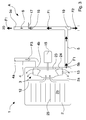
- an apparatus 1 for cooking foods in particular a combined convection and steam oven, comprising a cooking chamber 2 arranged for containing foods to be cooked on a plurality of shelves 25, fan means 3 suitable for circulating air and/or steam inside said cooking chamber 2, first conduit means 4 and second conduit means 5 that connect the inside of said cooking chamber 2 to an external environment 20 in which the apparatus is located.
- the first conduit means 4 enables air from the external environment 20 to enter said cooking chamber 2 whilst the second conduit means 5 enables the cooking chamber 2 to be ventilated, i.e. enables excess air and/or steam to exit therefrom.
- the first conduit means 4 comprises at least a first conduit provided with a first end 4a, communicating with the external environment 20, and with a second end 4b that leads inside the cooking chamber 2, at a rear disc 23 to which main blades 13 of the fan means 3 are fixed.
- the latter is housed in a ventilation gap 2a of the cooking chamber 2 that is separated from a cooking zone 2b by a separating wall 12.
- the dynamic effect due to the rotation of the fan means 3 creates an air vacuum in a zone adjacent to the second end 4b of the conduit 4, so as to suck air from outside inside the cooking chamber 2 through said first conduit 4. More precisely, locally in said zone a decrease in air pressure is determined, the value of which becomes less than that of the pressure in the external environment 20, enabling air to enter.
- This dynamic suction/vacuum effect can be further increased by using a series of auxiliary blades 24 fixed to the rear disc 23 of the fan means 3, on a side opposite the main blades 13.
- the second conduit means 5 comprises at least a second conduit provided with respective first end 5a, communicating with the external environment 20, and a respective second end 5b that leads inside the cooking chamber 2, at the ventilation gap 2a, in a zone outside the zone occupied by the fan means 3.
- valve means 6 suitable for closing or opening said conduit to prevent or enable a mixture of air and steam to exit.
- the valve means 6 comprises, for example, a butterfly valve of known type, driven, for example, by an actuator of known type and not illustrated in the Figures.
- the apparatus 1 comprises condensing means 10 suitable for condensing and/or filtering steam exiting the cooking chamber 2 through the first conduit 4 in a second operating condition B of the cooking apparatus 1, in which the valve means 6 is shut and prevents the mixture of air and steam exiting through the second conduit 5 ( Figure 2).
- the condensing means 10 comprises a boxed casing 11 divided internally into a first cavity 11a and a second cavity 11b, partially separated by a baffle 14.
- the respective first end 4a of the first conduit 4 leads inside the first cavity 11a, whilst the second cavity 11b is directly connected to the external environment 20 by means of a connecting opening 11c.
- Injecting means 7 is fixed to the boxed casing 11 and arranged for spraying and nebulising a jet of water 8 inside the second cavity 11b in order to condense and/or filter the mixture of air and steam exiting the cooking chamber 2 through the first conduit 4.
- Draining means 9 is provided on the bottom of the second cavity 11b to collect and discharge the condensate that forms during operation.
- the baffle 14 prevents splashes and/or drops of water introduced by the injecting means 7 from finishing inside the first conduit 4 and, therefore, the cooking chamber 2. Further, the end 4a of the conduit 4 is located at a higher level than the bottom of the casing 11, so as to prevent possible standing water on the bottom from flowing inside the cooking chamber 2.
- further injecting means 17 suitable for spraying and nebulising a further jet of water 18 that is necessary for condensing and/or filtering the steam exiting the cooking chamber 2 in the first operating condition A of the apparatus 1.
- Further draining means 19 is provided for collecting and discharging the condensate.
- the operation of the cooking apparatus 1 provides in the first operating condition A for the valve means 6 being arranged in an open position to enable the excess air and steam to exit through the second conduit 5 and in this manner reduce the percentage of humidity inside the cooking chamber 2 during cooking of food.
- the exiting flow of air and steam is indicated by the arrows F1 in Figure 1.
- the flow of sucked air is a function of the vacuum created by the fan means 3 and of the pressure difference existing between the inside of the cooking chamber 2 and the external environment 20. This flow can possibly be varied and adjusted by acting on the rotation speed of the fan means 3 i.e. motor means 15 assigned to the driving thereof.
- valve means 6 In the second operating condition B of the cooking apparatus 1, the valve means 6 is arranged in a shut position so as to prevent the air and steam exiting from the cooking chamber 2. The excess steam inside the latter can thus exit only through the first conduit 4, which is in flow connection with the external environment 20.
- the flow of steam is indicated by the arrows F4 in Figure 2.
- the excess steam can exit only when inside the cooking chamber 2 a threshold pressure is exceeded such as to overcome the vacuum generated by the fan means 3. More precisely, to this threshold pressure in the cooking chamber 2 there corresponds pressure at the second end 4b above the pressure of the external environment 20. This enables a high percentage of steam to be maintained inside the cooking chamber 2 and dangerous increases in pressure to be avoided at the same time.
- the injecting means 7 is activated and sprays a nebulised jet of water to enable the exiting steam to be condensed (arrow F5 of Figure 2).
- the valve means 6 can be opened manually or automatically by means of a control unit of the apparatus 1, which control unit is not illustrated, that controls the temperature and/or pressure and/or humidity level inside the cooking chamber 2.
- the apparatus 1 can be provided with sensors, such as thermometers, gauges, humidity gauges, located inside the cooking chamber 2 and connected to the control unit.
- temperature sensors can be provided that are arranged inside the conduit 4 or in one of the two cavities of the condensing device 10 so as to identify the moment at which the pressure in the cooking chamber exceeds the set threshold and the excess steam starts to exit through the conduit 4.
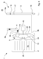
- FIGs 3 and 4 there is illustrated a second embodiment of a cooking apparatus 1a according to the invention.
- the cooking apparatus 1a is devoid of the condensing means 10 and of the corresponding injecting means 7, so that the end 4a of the conduit 4 leads directly into the environment outside the apparatus 1a.
- the operation of the apparatus 1a is completely similar to the operation of the apparatus 1 illustrated in Figures 1 and 2, with the sole difference that the flow of incoming air shown by the arrow F3 enters directly from the external environment inside the conduit 4.
- the flow of steam F4 exits directly into the external environment through the conduit 4 without undergoing any condensation or cooling.
Landscapes
- Engineering & Computer Science (AREA)
- Chemical & Material Sciences (AREA)
- Combustion & Propulsion (AREA)
- Mechanical Engineering (AREA)
- General Engineering & Computer Science (AREA)
- Cookers (AREA)
- Commercial Cooking Devices (AREA)
Applications Claiming Priority (1)
| Application Number | Priority Date | Filing Date | Title |
|---|---|---|---|
| IT000354A ITMO20060354A1 (it) | 2006-11-03 | 2006-11-03 | Apparato di cottura |
Publications (2)
| Publication Number | Publication Date |
|---|---|
| EP1921387A2 true EP1921387A2 (fr) | 2008-05-14 |
| EP1921387A3 EP1921387A3 (fr) | 2012-08-29 |
Family
ID=38983507
Family Applications (1)
| Application Number | Title | Priority Date | Filing Date |
|---|---|---|---|
| EP07117870A Withdrawn EP1921387A3 (fr) | 2006-11-03 | 2007-10-04 | Appareil de cuisson |
Country Status (4)
| Country | Link |
|---|---|
| US (1) | US20080105138A1 (fr) |
| EP (1) | EP1921387A3 (fr) |
| CN (1) | CN101172019B (fr) |
| IT (1) | ITMO20060354A1 (fr) |
Cited By (5)
| Publication number | Priority date | Publication date | Assignee | Title |
|---|---|---|---|---|
| WO2010100149A3 (fr) * | 2009-03-06 | 2010-11-18 | Eloma Gmbh | Combinaison d'appareils de cuisson |
| CN101991350A (zh) * | 2010-11-18 | 2011-03-30 | 深圳市嘉兰图设计有限公司 | 一种双重加热蒸具 |
| ITPD20130231A1 (it) * | 2013-08-08 | 2015-02-09 | Unox Spa | Forno con dispositivo di immissione di aria ed estrazione di aria e/o vapore dalla camera di cottura del forno, in particolare per il controllo dell'umidita' in detta camera di cottura |
| EP2468102B1 (fr) * | 2010-12-23 | 2019-04-03 | Miele & Cie. KG | Appareil de cuisson |
| EP3715725A1 (fr) * | 2019-03-29 | 2020-09-30 | Vestel Beyaz Esya Sanayi Ve Ticaret A.S. | Dispositif de cuisson et procédé de fonctionnement du dispositif de cuisson |
Families Citing this family (22)
| Publication number | Priority date | Publication date | Assignee | Title |
|---|---|---|---|---|
| EP2338390A1 (fr) * | 2009-12-28 | 2011-06-29 | Koninklijke Philips Electronics N.V. | Contrôle de la puissance pendant la diminuation de température d'une application de vapeur |
| IT1402113B1 (it) * | 2010-10-08 | 2013-08-28 | Giorik Spa | Forno per la cottura a vapore di alimenti |
| EP2697569B1 (fr) * | 2011-04-15 | 2017-07-12 | BSH Hausgeräte GmbH | Appareil de cuisson à la vapeur, en particulier four à vapeur |
| US9423150B2 (en) * | 2013-03-15 | 2016-08-23 | Accutemp Products, Inc. | Steam cooker |
| US9423139B2 (en) * | 2013-04-01 | 2016-08-23 | Convotherm Elektrogeraete Gmbh | Condensation management system and method |
| WO2016093481A1 (fr) * | 2014-12-10 | 2016-06-16 | 주식회사 효신테크 | Four de combinaison comprenant une fonction fumée intégrée |
| KR101530048B1 (ko) * | 2014-12-10 | 2015-06-22 | 주식회사 효신테크 | 내장형 훈연 기능을 포함한 콤비 오븐 |
| KR101531350B1 (ko) * | 2014-12-10 | 2015-06-24 | 주식회사 효신테크 | 열 손실을 줄여 열 효율을 높인 조리용 콤비 오븐 |
| US10143205B2 (en) * | 2015-01-26 | 2018-12-04 | Guy E. Buller-Colthurst | Air stream manipulation within a thermal processing oven |
| TWI649053B (zh) * | 2015-06-25 | 2019-02-01 | 華小玲 | Cooking system |
| RU2719850C2 (ru) | 2015-09-24 | 2020-04-23 | Киёми ЙОСИМУРА | Устройство для приготовления пищи |
| BR112018008687B1 (pt) | 2015-10-30 | 2022-06-14 | Koninklijke Philips N.V. | Fritadeira à base de ar, e método de preparação de ingredientes alimentícios em uma fritadeira à base de ar |
| DE102016215650A1 (de) * | 2016-08-19 | 2018-02-22 | BSH Hausgeräte GmbH | Haushaltsgargerät |
| CN106377173A (zh) * | 2016-11-08 | 2017-02-08 | 英联斯特(广州)餐饮设备有限公司 | 一种具有喷雾功能的电焗炉 |
| CN113647800B (zh) * | 2017-05-25 | 2022-07-15 | 三星电子株式会社 | 蒸汽烹调器 |
| CN108013737B (zh) * | 2018-01-24 | 2023-07-14 | 广东格匠实业有限公司 | 一种蒸汽冷凝装置以及蒸汽锅 |
| US10986843B2 (en) * | 2018-02-05 | 2021-04-27 | Alto-Shaam, Inc. | Combination drain system for multizone oven |
| US12253264B2 (en) * | 2018-02-05 | 2025-03-18 | Alto-Shaam, Inc. | Steam generation and drain system for modular oven |
| CN110367838B (zh) * | 2018-04-13 | 2022-04-05 | 九阳股份有限公司 | 一种节能烹饪器具 |
| CN112869583B (zh) * | 2018-10-23 | 2022-07-29 | 贵阳高新惠诚食品有限公司 | 一种带有搅拌功能的食物烘烤机 |
| US11339974B2 (en) * | 2019-03-21 | 2022-05-24 | Bsh Home Appliances Corporation | Multifunctional steam cooking appliance with active air inlet |
| DE102019210395A1 (de) * | 2019-07-15 | 2021-01-21 | BSH Hausgeräte GmbH | Gargerätevorrichtung |
Family Cites Families (24)
| Publication number | Priority date | Publication date | Assignee | Title |
|---|---|---|---|---|
| US3744474A (en) * | 1971-03-01 | 1973-07-10 | Beatrice Foods Co | Steam cooking apparatus and method |
| FR2516351B1 (fr) * | 1981-11-13 | 1987-01-16 | Dumont Sa | Four a combustion par convection d'air, notamment pour boulangeries-patisseries |
| DE3215812A1 (de) * | 1982-04-28 | 1983-11-03 | Convotherm-Elektrogeräte GmbH, 8190 Wolfratshausen | Vorrichtung zur waermebehandlung von substanzen, insbesondere nahrungsmitteln |
| GB8324514D0 (en) * | 1983-09-13 | 1983-10-12 | Baker Perkins Holdings Plc | Tunnel ovens |
| US4648377A (en) * | 1986-05-01 | 1987-03-10 | Hobart Corporation | Gas convection oven and heat exchanger therefor |
| IT1234689B (it) * | 1989-03-21 | 1992-05-26 | Zanussi Grandi Impianti Spa | Forno di cottura a convezione forzata |
| US4963091A (en) * | 1989-10-23 | 1990-10-16 | Surface Combustion, Inc. | Method and apparatus for effecting convective heat transfer in a cylindrical, industrial heat treat furnace |
| IT1253156B (it) * | 1991-10-29 | 1995-07-10 | Dispositivo di sicurezza contro la sovrappressione nel boiler ed il risucchio in camera, particolarmente nelle apparecchiature per la cottura dei cibi. | |
| FR2754334B1 (fr) * | 1996-10-07 | 1998-12-18 | Bourgeois Prod Coop | Four a vapeur et convexion forcee |
| EP0926449B2 (fr) * | 1997-12-23 | 2003-05-21 | eloma GmbH Grossküchentechnik | Procédé pour déshumidifier un espace à cuire d'un dispositif pour cuire à la vapeur et dispositif approprié |
| ATE276490T1 (de) * | 1998-12-30 | 2004-10-15 | Menu System Ag | Verfahren und einrichtung zur zubereitung von speisen. |
| DE29914472U1 (de) * | 1999-08-23 | 1999-12-09 | AEG Hausgeräte GmbH, 90429 Nürnberg | Garofen mit Außengebläse zum Gasauslaß |
| DE19955820A1 (de) * | 1999-11-19 | 2001-06-07 | Rational Ag | Gargerät mit druckfestem Garraum und Drucklufterzeugereinheit |
| DE10037905C2 (de) * | 2000-08-03 | 2002-10-31 | Rational Ag | Garraum mit Über- und/oder Unterdruck |
| FR2818359B1 (fr) * | 2000-12-15 | 2004-05-14 | Thirode Grandes Cuisines Poligny | Dispositif de four et procede de commande d'un four |
| ES2204822T3 (es) * | 2001-02-28 | 2004-05-01 | Angelo Po Grandi Cucine S.P.A. | Camara de coccion que tiene un dispositivo para la deshumidificacion en un aparato para coccion de alimentos. |
| CN1416771A (zh) * | 2001-11-08 | 2003-05-14 | 卢振涛 | 一种饮水机散热装置 |
| KR100419208B1 (ko) * | 2002-05-27 | 2004-02-21 | 삼성전자주식회사 | 벽걸이형 전자렌지 |
| DE10245773C1 (de) * | 2002-09-26 | 2003-12-04 | Wiesheu Gmbh | Vorrichtung zur Wärmebehandlung von Lebensmitteln |
| DE10351476B4 (de) * | 2003-11-04 | 2008-09-25 | Rational Ag | Gargerät zur verbesserten Frischluftzufuhr |
| GB0518186D0 (en) * | 2005-09-07 | 2005-10-12 | Fylde Thermal Engineering Ltd | Tunnel oven |
| JP4106382B2 (ja) * | 2006-05-25 | 2008-06-25 | シャープ株式会社 | 加熱調理器 |
| ITMO20060306A1 (it) * | 2006-09-28 | 2008-03-29 | Angelo Po Grandi Cucine Spa | Dispositivo nebulizzatore per forni |
| ITMO20070200A1 (it) * | 2007-06-13 | 2008-12-14 | Angelo Grandi Cucine Societa P | Apparato di cottura ed affumicatura |
-
2006
- 2006-11-03 IT IT000354A patent/ITMO20060354A1/it unknown
-
2007
- 2007-10-04 EP EP07117870A patent/EP1921387A3/fr not_active Withdrawn
- 2007-10-10 US US11/907,264 patent/US20080105138A1/en not_active Abandoned
- 2007-10-19 CN CN2007101818722A patent/CN101172019B/zh not_active Expired - Fee Related
Cited By (5)
| Publication number | Priority date | Publication date | Assignee | Title |
|---|---|---|---|---|
| WO2010100149A3 (fr) * | 2009-03-06 | 2010-11-18 | Eloma Gmbh | Combinaison d'appareils de cuisson |
| CN101991350A (zh) * | 2010-11-18 | 2011-03-30 | 深圳市嘉兰图设计有限公司 | 一种双重加热蒸具 |
| EP2468102B1 (fr) * | 2010-12-23 | 2019-04-03 | Miele & Cie. KG | Appareil de cuisson |
| ITPD20130231A1 (it) * | 2013-08-08 | 2015-02-09 | Unox Spa | Forno con dispositivo di immissione di aria ed estrazione di aria e/o vapore dalla camera di cottura del forno, in particolare per il controllo dell'umidita' in detta camera di cottura |
| EP3715725A1 (fr) * | 2019-03-29 | 2020-09-30 | Vestel Beyaz Esya Sanayi Ve Ticaret A.S. | Dispositif de cuisson et procédé de fonctionnement du dispositif de cuisson |
Also Published As
| Publication number | Publication date |
|---|---|
| ITMO20060354A1 (it) | 2008-05-04 |
| US20080105138A1 (en) | 2008-05-08 |
| CN101172019A (zh) | 2008-05-07 |
| EP1921387A3 (fr) | 2012-08-29 |
| CN101172019B (zh) | 2013-03-27 |
Similar Documents
| Publication | Publication Date | Title |
|---|---|---|
| EP1921387A2 (fr) | Appareil de cuisson | |
| KR102800035B1 (ko) | 조리 제품 가열용 장치 | |
| RU2401960C2 (ru) | Нагревательная печь | |
| JPH02279114A (ja) | 調理装置 | |
| US10401036B2 (en) | Humidity flushing system | |
| CN110115517B (zh) | 用于多区烤箱的组合排放系统 | |
| EP2005831A2 (fr) | Appareil de cuisson et de fumage | |
| US20140291312A1 (en) | Condensation management system and method | |
| JPH08501243A (ja) | 蒸気室付き高性能調理オーブン | |
| JP2005525524A (ja) | コンビネーションオーブン用の湿度制御システム | |
| CN111685577B (zh) | 烹饪器具及其控制方法、控制装置和计算机可读存储介质 | |
| EP1669676B1 (fr) | Four a vapeur | |
| EP1975516B1 (fr) | Four de cuisson et son procédé de fonctionnement | |
| CN118338820A (zh) | 具有能水平移出的蒸汽处理抽屉的家用烹饪器具 | |
| KR20110012038U (ko) | 보조 흡입구가 구비된 주방용 레인지 후드 장치 | |
| EP1767869A2 (fr) | Appareil de cuisson | |
| EP2519776B1 (fr) | Four avec conduit de ventilation | |
| WO2020229941A1 (fr) | Appareil et procédé pour optimiser la distribution de chaleur à l'intérieur d'un four pour cuire des aliments et four comprenant ledit appareil | |
| EP3059504A1 (fr) | Four de cuisine | |
| EP3431884B1 (fr) | Four de cuisson pour aliments | |
| CN219069915U (zh) | 一种蒸烤箱的排湿风道系统 | |
| JP2003227612A (ja) | スチームオーブン | |
| JP4737048B2 (ja) | 排風還流式穀物乾燥機 | |
| WO2019042667A1 (fr) | Four comprenant un système d'évacuation de vapeur | |
| CN212186137U (zh) | 一种蒸箱 |
Legal Events
| Date | Code | Title | Description |
|---|---|---|---|
| PUAI | Public reference made under article 153(3) epc to a published international application that has entered the european phase |
Free format text: ORIGINAL CODE: 0009012 |
|
| AK | Designated contracting states |
Kind code of ref document: A2 Designated state(s): AT BE BG CH CY CZ DE DK EE ES FI FR GB GR HU IE IS IT LI LT LU LV MC MT NL PL PT RO SE SI SK TR |
|
| AX | Request for extension of the european patent |
Extension state: AL BA HR MK RS |
|
| PUAL | Search report despatched |
Free format text: ORIGINAL CODE: 0009013 |
|
| AK | Designated contracting states |
Kind code of ref document: A3 Designated state(s): AT BE BG CH CY CZ DE DK EE ES FI FR GB GR HU IE IS IT LI LT LU LV MC MT NL PL PT RO SE SI SK TR |
|
| AX | Request for extension of the european patent |
Extension state: AL BA HR MK RS |
|
| RIC1 | Information provided on ipc code assigned before grant |
Ipc: F24C 15/20 20060101AFI20120726BHEP |
|
| AKY | No designation fees paid | ||
| REG | Reference to a national code |
Ref country code: DE Ref legal event code: R108 |
|
| REG | Reference to a national code |
Ref country code: DE Ref legal event code: R108 Effective date: 20130508 |
|
| STAA | Information on the status of an ep patent application or granted ep patent |
Free format text: STATUS: THE APPLICATION IS DEEMED TO BE WITHDRAWN |
|
| 18D | Application deemed to be withdrawn |
Effective date: 20130301 |