EP1925351A1 - Élément de filtration pour un plateau filtrant de presse - Google Patents
Élément de filtration pour un plateau filtrant de presse Download PDFInfo
- Publication number
- EP1925351A1 EP1925351A1 EP06023831A EP06023831A EP1925351A1 EP 1925351 A1 EP1925351 A1 EP 1925351A1 EP 06023831 A EP06023831 A EP 06023831A EP 06023831 A EP06023831 A EP 06023831A EP 1925351 A1 EP1925351 A1 EP 1925351A1
- Authority
- EP
- European Patent Office
- Prior art keywords
- filter
- flange
- passage
- filter element
- element according
- Prior art date
- Legal status (The legal status is an assumption and is not a legal conclusion. Google has not performed a legal analysis and makes no representation as to the accuracy of the status listed.)
- Granted
Links
Images


Classifications
-
- B—PERFORMING OPERATIONS; TRANSPORTING
- B01—PHYSICAL OR CHEMICAL PROCESSES OR APPARATUS IN GENERAL
- B01D—SEPARATION
- B01D25/00—Filters formed by clamping together several filtering elements or parts of such elements
- B01D25/001—Making filtering elements not provided for elsewhere
-
- B—PERFORMING OPERATIONS; TRANSPORTING
- B01—PHYSICAL OR CHEMICAL PROCESSES OR APPARATUS IN GENERAL
- B01D—SEPARATION
- B01D25/00—Filters formed by clamping together several filtering elements or parts of such elements
- B01D25/12—Filter presses, i.e. of the plate or plate and frame type
- B01D25/176—Filter presses, i.e. of the plate or plate and frame type attaching the filter element to the filter press plates, e.g. around the central feed hole in the plates
-
- B—PERFORMING OPERATIONS; TRANSPORTING
- B01—PHYSICAL OR CHEMICAL PROCESSES OR APPARATUS IN GENERAL
- B01D—SEPARATION
- B01D2201/00—Details relating to filtering apparatus
- B01D2201/40—Special measures for connecting different parts of the filter
- B01D2201/4084—Snap or Seeger ring connecting means
Definitions
- the invention relates to a filter element for a filter press plate, with two filter areas and a passage for passing a liquid to be filtered, through which the two filter areas are interconnected.
- Filter press plates for plate filter presses are known. Such filter press plates have a generally centrally disposed flow opening, which serves to pass the liquid to be filtered. In the plate filter press several filter press plates are arranged side by side and pressed so that the flow openings are aligned and form a channel, is fed through the liquid to be filtered in the filter.
- the filter areas in the region of the flow opening is for example from the US 6,932,906 B2 a flexible passage tube known.
- the known passage tube at its opposite end faces, the known passage tube in each case has a flange, on which a filter area is arranged.
- the object of the invention is to provide a filter element for a filter press plate, which can be particularly easily mounted on a filter press plate with high reliability and efficiency.
- a filter element is characterized in that the passage is modularly formed with at least two separate flange elements, wherein each of the flange has a passage opening for the liquid to be filtered and wherein on the flange each one of the two filter areas is arranged, and that Connecting means are provided, with which the two flange elements are connected to each other at aligned through holes.
- a basic idea of the invention can be seen to form the passage in several parts with at least two separate elements, wherein each element has one of the two Filter areas is attached.
- the elements are connected to one another via connecting means.
- the connecting means are suitably designed so that they allow a connection of the two flange elements without the use of tools.
- the connecting means are designed so that a connection between the two flange elements by relative movement of the flange elements to each other, in particular by compression and / or rotation can be produced.
- the connecting means may be provided, for example, for a non-positive and / or a positive connection.
- the connecting means have a connecting tube on which the two flange elements are arranged.
- the passage is formed with a further element, the connecting tube, on which on the one hand the first flange element and on the other hand the second flange element is fastened, so that the two flange elements are connected to one another via the connecting tube.
- the connection means may provide elements for a direct connection between have the two flange elements.
- a connecting tube can in particular serve to compensate for diameter and / or thickness differences of the filter press plate.
- a connecting pipe allows the filter element to be easily adapted to different panel thicknesses.
- the connecting means can be designed such that the flange elements can be fastened to one another at different distances from the connecting tube.
- a plurality of latching devices can be provided on the outside of the connecting tube and / or on the flange elements, which hold the flange elements at different distances from one another on the connecting tube.
- at least one stop in particular a stop ring, is provided on the connecting tube, which limits a relative movement of at least one flange element with respect to the connecting tube.
- the connecting tube may also have a variable length to compensate for different thicknesses in the filter press plate.
- the connecting pipe can for example have a flexible material and / or bellows-shaped.
- the connecting means are formed so that the two flange elements, in particular in a defined rotational position, rotatably connected to each other.
- This allows a directed assembly of the two filter areas, in which they are arranged from the beginning without angular offset in their desired position in which they cover the filter press plate as well as possible.
- the connecting means suitably at least one positioning element.
- the positioning element can be, for example, an axially extending projection and / or an axially extending groove which is provided on one of the flange elements and / or on the connecting tube and which engages with a corresponding element on the adjacent flange element and / or on the adjacent connecting tube Intervention is.
- Such an additional positioning element is particularly advantageous if the connecting means have such a snap closure, which would basically allow a rotation of the two flange elements against each other.
- the two flange elements are rotatable relative to each other.
- the flange elements are arranged radially on the outside of the connecting pipe. According to this embodiment, the flange elements are pushed over the connecting tube.
- a passageway through the passage may be formed in this case by an inner wall of the connecting pipe, that is, the inner wall of the connecting pipe is in contact with the liquid flowing through the passage. The inner walls of the flange lie against the connecting pipe.
- the through-channel is formed both by the inner wall of the connecting tube and by the inner walls of the flange.
- the inner walls of the flange elements are at least partially aligned with the inner wall of the connecting tube. According to this embodiment are in the cross section of the passage channel at the transition from the channel region, the is formed by the flange, is given to the channel region, which is formed by the connecting pipe, no cracks, so that the flow resistance is particularly low.
- the connecting means may for example have a screw cap or a bayonet lock, which can be brought by rotation in a secured position and can be solved by counter rotation.
- the connecting means have at least one snap closure.
- the snap closure can be formed, for example, for a connection of the flange elements with one another or, if appropriate, for a connection of the flange elements to the connecting tube.
- the snap closure comprises at least one deformable and / or movable profile element which is received in a corresponding recess.
- at least one annular profile element can be provided.
- the snap element and in particular the corresponding recess may be formed segment-like.
- a plurality of segment-like profile elements and / or depressions are provided at the handling of the passage.
- a plurality of profile elements and / or depressions may be provided axially offset one above the other, preferably in one segment. It can also be provided several segments.
- annular Snap elements or recesses may be provided, which rotate around the entire circumference.
- the profile element of the snap closure is bendable formed as Biegeschnappelement.
- the snap closure may have at least one radially acting bending snap element. This may in particular be understood as meaning such an element which can be moved by bending radially with respect to the passage channel formed in the passage. In principle, tangentially acting snap elements are also conceivable.
- the connecting means in particular the snap closure element, are designed such that a non-destructive release of the connection between the two flange elements is possible. This can be done by choosing a suitable angle on the snap element. As a result, a particularly simple disassembly of the filter element is made possible by the filter press plate.
- the passage may also be formed at least partially resilient.
- a further preferred embodiment of the invention is that the snap closure has a plurality of, in particular axially offset, profile elements, which are preferably arranged radially inwardly on at least one of the flange elements and / or radially outside of the connecting tube.
- Such an embodiment makes it possible to fix the flange element at a plurality of axial positions. This in turn makes it possible to adjust the length of the passage to the thickness of the filter press plate.
- the latching closure has at least one profile element arranged on the front side on the connecting tube, which preferably protrudes through one of the flange elements.
- the profile element protrudes in the axial direction on the connecting pipe.
- a radial passage may in particular be understood to mean a passage through the wall of the passage transversely to the longitudinal direction of the passage.
- at least one sealing element can be provided between the flange elements with one another and / or between the flange elements and the connecting tube.
- the effectiveness of the filter element can be further increased by providing a sealing element, in particular a sealing ring, between at least one of the flange elements and the connecting tube.
- a sealing element in particular a sealing ring
- transitions between the flange element and connecting tube can be sealed and an undesired flow through the wall of the multipart passage can be prevented.
- the sealing element is suitably designed as an elastomeric seal and is preferably provided in the connecting region between adjacent elements.
- the sealing element can be sprayed on the flange. This is particularly advantageous if the flange element has further elastomeric regions in addition to the sealing element.
- the sealing element can also be accommodated, for example, in a corresponding groove on the flange element or on the connecting tube.
- a particularly long service life can be given by at least one filter area being connected to the passage, in particular the flange element, via a preferably ring-like adapter element.
- the adapter element may be formed flat and / or as a cloth, for example as a fabric and / or film.
- the filter area is not directly connected to the passage. Rather, the filter area is attached to an adapter element, which in turn is in turn connected to the passage.
- the adapter element is preferably made of a different material compared to the adjacent region of the passageway. But it can also be provided an integrated design, in which the filter areas are directly connected to the flange elements, for which in particular a material connection can be provided.
- At least one of the two filter areas or optionally the adapter element with the passage cohesively connected, in particular welded and / or glued, is.
- a connection can be generated in particular by laser welding and / or ultrasonic welding.
- material of the passage penetrates the filter area or the adapter element.
- a particularly reliable connection between the passage and the filter area is given by the fact that at least one retaining mandrel is provided at the passage at least one filter area and / or adapter element for piercing the filter area or the adapter element.
- This retaining pin is a positive connection between the filter area or adapter element and passage made.
- the retaining mandrel is tapered and in particular is conical. As a result, the piercing of the filter area is facilitated during manufacture.
- the retaining mandrel is suitably dimensioned so that it penetrates the tissue, but not damaged.
- the diameter of the retaining pin is smaller than the mesh size of the fabric.
- the mandrel can also be dimensioned so that it widens the mesh of the tissue that it penetrates.
- a particularly easy to produce and at the same time reliable attachment of a filter area at the passage is given by the fact that at least one of the flange is in two parts, in particular with a retaining ring and a fixing ring, and that in particular one of the two filter areas and / or the adapter element between the two parts is received and attached to the flange.
- the flange element extends in the region of the attachment on both flat sides of the filter region or of the adapter element, so that the fastening means are protected by the flange element.
- the retaining ring and the fixing ring on the retaining mandrel preferably cohesively, be connected.
- the economy can be increased according to the invention characterized in that the two flange elements are designed to be identical. In this case, only one type of flange element has to be stored.
- the passage has a plurality of wall thickness tapers for increasing flexibility.
- the Wall thickness tapers may be provided in a tubular portion and / or in a radial portion of the passage. Additionally or alternatively, cuts may also be provided for the wall thickness tapers.
- the wall thickness tapers suitably extend in the axial direction of the passage.
- a filter region may, in particular, be understood as meaning a filter cloth, for example a filter fabric, a filter fabric and / or a filter membrane.
- the two filter areas can be separate, but in principle also connected, in particular in one piece, be formed. Due to the modular construction of the passage, it is not necessary to pass through a filter area through the flow opening of the filter press plate during assembly of the filter element. Thus, for example, it may be provided to beat a coherent filter cloth around a filter press plate, so that this filter cloth forms a filter region on both sides of the filter press plate, wherein the two filter regions are additionally connected to one another via the passage.
- the passage is made of a plastic, in particular of a thermoplastic.
- the passage according to the invention can also be referred to as barrel neck.
- a filter element can be characterized in that the passage has two end-side flange regions on which the filter regions are arranged and an intermediate middle region, wherein the passage in at least one of the flange regions has a higher flexibility than in the middle region.
- the passage in the flange portions which hold the passage in the filter press plate and which are cross-sectionally larger than the central region, more flexible than in the central region, which serves for the passage of the liquid to be filtered.
- a flexibility is thus specifically provided in the areas that need to be deformed during installation or removal of the passage in or out of the filter press plate, whereas in areas where no deformation is required, less flexibility is given.
- an easy to install and disassemble filter element is provided, which can be used with high reliability even at high operating pressures.
- a preferred embodiment of the invention is that the passage in the flange area has a different material than in the middle area.
- the different flexibility is provided by a different material composition.
- the passage may have, for example in the middle region, a tubular element, on the end face of which in the flange region a plurality of tabs are provided, which can each be angled over a film hinge to form a flange.
- the film hinge makes it possible to arrange the tabs when passing through the filter press plate so that they lie within the cross section of the tubular element and in any case does not hinder the movement of the tubular element through the filter press plate.
- the tabs After pushing through the passage of the tabs can be angled, whereby the cross-section is widened so much that a retraction of the passage through the filter press plate is no longer possible.
- these can be connected, for example, to one of the filter areas and / or fixed by a securing ring.
- the filter areas are each provided with at least one hole, wherein the filter areas are secured in the region of the hole at the passage.
- the holes of the filter areas are arranged in alignment with the passage openings of the flange elements.
- Another aspect of the invention lies in a method for filtering a liquid, in which the liquid is passed through the filter areas of a filter element according to the invention.
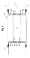
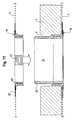
- a first embodiment of a filter element according to the invention is shown in Figures 1 to 3.
- the filter element has two filter areas formed as a filter, flat, approximately parallel filter areas 5, 5 ', which are each provided with a hole. In the area of its hole edge, the two filter areas 5, 5 'are fastened to a tubular passage 1.
- a passageway 11 is formed, which extends through the passage 1 and the filter areas 5, 5 'and which serves for the passage of liquid during operation of a filter plate press.
- the detailed structure of the passage 1 is shown in particular in FIGS. 1 and 3.
- the passage 1 has two separate flange elements 10, 10 ', wherein the filter region 5 is arranged on the flange element 10 and the filter region 5' on the flange element 10 '.
- the two flange elements 10, 10 ' are of identical construction. Due to the identical design, only the flange 10 will be described in more detail below.
- the flange 10 is formed in two parts and has a retaining ring 15 and a disc-like fixing ring 16.
- the retaining ring 15 consists of an axially extending, approximately sleeve-shaped pipe section 18, to which the front side a radially extending, annular disc-like flange portion 19 connects.
- the fixing ring 16 also extends radially and lies flat against the flange portion 19 of the retaining ring 15. Between the fixing ring 16 and the flange portion 19 of the retaining ring 15 of the filter portion 5 is received and secured by a seam 13 on the retaining ring 15 and the fixing ring 16.
- a connecting tube 20 is provided which connects the two flange elements 10, 10'.
- the connecting tube 20 and the flange elements 10, 10 ' are formed with the same inner cross section, so that no cross-sectional changes occur in the passage 11 at the transition between the connecting tube 20 and the flange elements 10, 10'.
- a profile element 30 is provided on the front side of the connecting tube 20, which protrudes axially on the connecting tube 20.
- a corresponding profile element 40 protrudes axially from the end face on the pipe section 18 of the flange element 10.
- a snap closure is formed on a step 71, which fixes the flange element 10 to the through-channel 20.
- Analogously designed profile elements 30 'and 40' are provided on the opposite end face of the connecting tube 20 and on the second flange element 10 '.
- a sealing ring 23 is provided in the region of the profile elements 30 and 40.
- An analogously formed sealing ring 23 ' is arranged between the connecting tube 20 and the second flange element 10'.
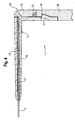
- FIG. 4 A further embodiment of a filter element according to the invention with a differently executed passage 1 is shown in broken longitudinal sectional view in Fig. 4.
- a profile element 31 designed as a radially acting bending snap element is provided on the sleeve-like tube section 18 of the retaining ring 15, which is used to connect flange element 10 and connecting tube 20 into a corresponding recess 41 in FIG the radially outer wall of the connecting tube 20 engages.
- the retaining ring 15 has in its pipe section 18 and in its flange 19 different rigid materials.
- a comparatively rigid, less flexible material is used in the pipe section 18, in particular in its areas in which the holding function is produced to the connecting pipe 20, a comparatively rigid, less flexible material is used in the pipe section 18, in particular in its areas in which the holding function is produced to the connecting pipe 20, a comparatively rigid, less flexible material is used in the pipe section 18, in particular in its areas in which the holding function is produced to the connecting pipe 20, a comparatively rigid, less flexible material is used.
- a comparatively flexible, deformable and less rigid material is used in particular, an elastomer can be used here.
- a sealing ring 23 is provided, which may consist of the same material as the flange portion 19th
- a plurality of holding thorns 17 are provided in the flange portion 19 of the holding ring 15, which penetrate the flat filter area 5 and thus hold in a form-fitting manner. At their tips, the mandrels 17 are welded cohesively to the fixing ring 16. The fixing ring 16 thus secures the filter area 5 at the thorns 17th
- the fixing ring 16 has a material of high flexibility.
- the fixing ring 16 and / or the retaining ring 15 in the region of the flange portion 19 may be made of a thermoplastic elastomer. This makes it possible to partially transform the passage 1 during disassembly of the filter element.
- polypropylene with a glass fiber reinforcement can be used as the material for the rigid pipe section 18.
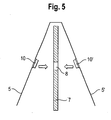
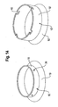
- FIG. 5 Another embodiment of a filter element according to the invention when mounted on a filter press plate 7 is shown in Fig. 5. As can be seen from FIG. 5, the two filter regions 5, 5 'can be provided on a one-piece filter cloth wrapped around the filter press plate 7.
- the filter element is mounted with separate flange elements 10, 10 '.
- the two flange elements 10, 10 ' are brought into contact with one another at a throughflow opening 8 of the filter press plate 7 and joined together to form the passage by means of connection means (not shown in FIG. 5).
- FIG. 6 Another embodiment of a filter element according to the invention for a filter press plate 7 is shown in different assembly stages in Figures 6 to 11.
- FIG. 6 shows a flange element 10 of the passage 1 in a partially sectioned, perspective view
- FIG. 7 shows the flange element 10 from FIG. 6 in a longitudinal section.
- a flat, annular adapter element 50 is arranged on the flange element 10.
- This adapter element 50 is made of a different material compared to the flange element 10 and projects radially beyond the flange element 10.
- holes 51 are provided in the adapter element 50. Through these holes 51, the flange member 10 passes through, whereby a positive connection between the flange 10 and adapter member 50 is given.
- the flange element 10 together with the adapter element 50 can be produced in particular in a two-stage injection molding process.
- the flange element 10 can be produced in the second stage, wherein material of the flange element 10 penetrates the holes 51 of the adapter element 50 produced in the first step.
- the adapter element 50 may consist of a material which has a particularly good compatibility with the filter region 5 to be attached.
- the adapter element 50 may comprise, for example, a fabric, a needle felt, a non-woven fabric, paper made using small thermoplastic fibers, heat and pressure, a film and / or a strong, non-fibrous film material, and may, for example, be plastic , Rubber and / or resin to increase the quality of the connection with the filter area 5.
- the adapter element 50 is suitably flexible.
- FIG. 8 shows a further method step in the production of a filter element according to the invention.
- the filter region 5 is arranged on the adapter element 50 and connected thereto.
- ultrasonic, hot gas, Schuelement- and / or microwave welding can be used.
- FIGS. 9 and 10 The further method for assembling the filter element is shown in FIGS. 9 and 10.
- a connecting tube 20 is provided.
- profile elements 42 are arranged on the inner circumferential surface of the flange 10 .
- These profile elements 42 are grouped in several segments 61 on the lateral surface of the flange 10.
- segments 61 are preferably a plurality of profile elements 42 ladder-like and arranged with axial offset one above the other.
- To the profile elements 42 corresponding profile elements 32 are arranged on the outer lateral surface of the connecting tube 20.
- These profile elements 32 are arranged in segments, wherein also in each segment preferably a plurality of profile elements ladder-like and can be arranged with axial offset one above the other.
- a single profile element 32 or 42 can also be provided in each segment.
- the profile elements 32 and 42 form a snap closure, which allows insertion of the connecting tube 20 in the direction of arrow in the flange 10, a subsequent withdrawal against the arrow direction, however, blocks.
- the wall thickness of the connecting tube 20 in the region of the at least one profile element 32 and / or the wall thickness of the flange element 10 in the region of the at least one profile element 42 can be reduced.
- a positioning element 63 designed as an axial web is provided on the flange element 10. This engages when pushed together in a not shown corresponding axial groove on the connecting tube 20 and thereby ensures a defined rotational position of the flange member 10 with respect to the connecting tube 20 safely.
- a stop ring 33 which limits the axial insertion of the connecting tube 20 into the flange element 10, is also provided on the outside of the connecting tube 20.
- FIGS. 9 and 10 moreover show, on the side of the abutment 33 facing away from the profile elements 32 on the lateral surface of the connecting tube 20 there are a large number of others axially offset profile elements 32 'provided.
- These further profile elements 32 ' correspond to profile elements 42' in the second flange element 10 'shown in FIG. 11.
- the corresponding profile elements 32 ', 42' allow an axial plugging of the flange element 10 'in the direction of the arrow shown in FIG. 11 and block an opposite movement.
- the profile elements 32 ', 42' are suitably formed analogous to the profile elements 32, 42 and grouped in particular in segments.
- flange 10 ' is a, not shown, and designed as an axial web positioning provided which engages when pushed together in a not shown corresponding axial groove in the connecting tube 20 and thereby ensures a defined rotational position of the flange 10' with respect to the connecting tube 20.
- the first flange element 10, together with the connecting tube 20 is carried through the flow opening 8 in the filter press plate 7, the filter area 5 coming into contact with the filter press plate 7.
- the flange 10 ' is placed on the filter tube 5 side facing away from the filter press plate 7 on the connecting tube 20, wherein the filter area 5' on the filter press plate 7 comes to rest and the two flange 10, 10 'with the connecting tube 20 to the finished passage 1 are joined together.
- the profile elements 32, 32 ', 42, 42' prevent subsequent removal of the flange 10, 10 'from the connecting pipe 20.
- the connecting pipe 20 for example Cut off, be shortened.
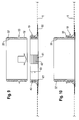
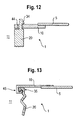
- FIG. 12 Another embodiment of a filter element according to the invention is shown in Fig. 12 in partial longitudinal section.
- a disc-like flange 10 is provided.
- a recess 44 is arranged in this disc-like flange 10.
- a hook-like profile element 34 of the closure device which is arranged on the front side of the connecting tube 20. This hook-like profile element 34 holds the flange element 10 on the connecting tube 20.
- FIG. 13 Another embodiment of a filter element according to the invention is shown in Fig. 13 in partial longitudinal section view.
- the flange 10 is formed approximately disc-like.
- a U-shaped profile element 35 is provided on the front side of the connecting tube 20.
- a corresponding U-shaped profile element 45 is arranged radially inwardly on the annular disk-like flange element 10.
- the connecting tube 20 is provided variable in length.
- this is made of a flexible material and executed bellows. Due to the variable length, the filter element can be adapted to different filter plate thicknesses.
- FIG. 14 A further embodiment of a passage for a filter element according to the invention prior to assembly of the two flange elements 10, 10 'is shown in FIG. 14.
- a bayonet closure is provided for connecting the two flange elements 10, 10 '.
- the connecting means on cylindrical profile elements 36 which radially on the pipe section 18 of the flange 10 protrude.
- On the front side of the pipe section 18 'of the second flange 10' corresponding receptacles 46 are provided for the profile elements 36.
- These receptacles 46 are formed as L-shaped cuts in the pipe section 18 'and allow a fixation of the flange 10 on the flange 10' by axial insertion of the flange 10 in the flange 10 'and subsequent relative rotation.
- the flange portions of the flange elements 10 and 10 ' are identified by the reference numerals 19 and 19'.
- the pipe section 18 or 18 'of the flange elements 10, 10' may be made of stainless steel, for example.
- a bicomponent plastic in particular a TPE plastic, is provided for the flange elements 10, 10 ', in particular for their pipe sections 18 and 18'.
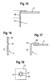
- FIG. 15 A further exemplary embodiment of a filter element according to the invention is shown in a partial sectional view in FIG. 15.
- the passage 1 has a flange region 80, on which the filter region 5 is arranged, and a sleeve-like middle region 81, which adjoins the flange region 80.
- the passage 1 is made in the flange portion 80 with a more flexible material than in the center portion 81, so that the flange portion 80 can be deformed.
- FIG. 16 shows in a sectional partial view the passage 1 of the filter element before the attachment of the filter area 5 and FIG. 17 after attachment of the filter area 5.
- FIG. 18 shows a plan view of the filter element after attachment of the filter area 5.
- lugs 90 are provided on the front side of the tubular passage 1, which surrounds the through-channel 11, which are articulated on the passage 1 via a respective film hinge 91.
- the tabs 90 can be brought into the aligned position shown in FIG. 16, in which they do not hinder the passage of the passage 1. If the passage 1 is pushed through the flow opening, the tabs 90, as shown in Figures 17 and 18, can be folded and connected to the filter area 5.
Landscapes
- Chemical & Material Sciences (AREA)
- Chemical Kinetics & Catalysis (AREA)
- Filtration Of Liquid (AREA)
- Lubrication Details And Ventilation Of Internal Combustion Engines (AREA)
Priority Applications (6)
| Application Number | Priority Date | Filing Date | Title |
|---|---|---|---|
| EP06023831A EP1925351B1 (fr) | 2006-11-16 | 2006-11-16 | Élément de filtration pour un plateau filtrant de presse |
| ES06023831T ES2324113T3 (es) | 2006-11-16 | 2006-11-16 | Elemento de filtro para una placa de filtro-prensa. |
| AT06023831T ATE428477T1 (de) | 2006-11-16 | 2006-11-16 | Filterelement für eine filterpressenplatte |
| DE502006003479T DE502006003479D1 (de) | 2006-11-16 | 2006-11-16 | Filterelement für eine Filterpressenplatte |
| US11/766,885 US20080017592A1 (en) | 2006-06-26 | 2007-06-22 | Filter element for a filter press plate |
| PCT/EP2007/007587 WO2008058583A2 (fr) | 2006-11-16 | 2007-08-30 | Élément filtre pour une plaque de filtre-presse |
Applications Claiming Priority (1)
| Application Number | Priority Date | Filing Date | Title |
|---|---|---|---|
| EP06023831A EP1925351B1 (fr) | 2006-11-16 | 2006-11-16 | Élément de filtration pour un plateau filtrant de presse |
Publications (2)
| Publication Number | Publication Date |
|---|---|
| EP1925351A1 true EP1925351A1 (fr) | 2008-05-28 |
| EP1925351B1 EP1925351B1 (fr) | 2009-04-15 |
Family
ID=38006717
Family Applications (1)
| Application Number | Title | Priority Date | Filing Date |
|---|---|---|---|
| EP06023831A Not-in-force EP1925351B1 (fr) | 2006-06-26 | 2006-11-16 | Élément de filtration pour un plateau filtrant de presse |
Country Status (5)
| Country | Link |
|---|---|
| EP (1) | EP1925351B1 (fr) |
| AT (1) | ATE428477T1 (fr) |
| DE (1) | DE502006003479D1 (fr) |
| ES (1) | ES2324113T3 (fr) |
| WO (1) | WO2008058583A2 (fr) |
Cited By (5)
| Publication number | Priority date | Publication date | Assignee | Title |
|---|---|---|---|---|
| EP2156873A1 (fr) | 2008-08-12 | 2010-02-24 | Sefar AG | Élément de filtre, anneau de fixation et procédé de filtrage |
| ITMS20090003A1 (it) * | 2009-04-08 | 2010-10-09 | Stefano Tongiani | Sistema di bloccaggio a cremagliera per filtropressaad azione combinata |
| EP2682171A4 (fr) * | 2011-02-28 | 2014-12-10 | Fairtech Invest Ltd | Élément de liaison pour élément de filtration de filtre-presse et filtre-presse comprenant un élément de liaison |
| TWI498145B (zh) * | 2010-06-16 | 2015-09-01 | Ishigaki Mech Ind | Filter cloth in the filter cloth hanging device and filter press |
| EP3482809A1 (fr) | 2017-11-14 | 2019-05-15 | Sefar AG | Élément de filtre et son procédé de fabrication |
Families Citing this family (1)
| Publication number | Priority date | Publication date | Assignee | Title |
|---|---|---|---|---|
| ES2383567B1 (es) * | 2009-08-06 | 2013-05-16 | Filtros Industriales, S.L. | Collarín para telas de filtración de un filtro prensa, y su correspondiente procedimiento de montaje. |
Citations (4)
| Publication number | Priority date | Publication date | Assignee | Title |
|---|---|---|---|---|
| GB2088231A (en) | 1980-12-02 | 1982-06-09 | P & S Filtration Ltd | Improvements in filter cloths for filter presses |
| WO1995007743A1 (fr) | 1993-09-14 | 1995-03-23 | Scapa Group Plc | Fixation d'element filtrant pour filtres-presses |
| WO2001089657A1 (fr) | 2000-05-23 | 2001-11-29 | Madison Filter Limited | Fixation d'element de filtration pour filtre-presse |
| DE10156199C1 (de) | 2001-11-15 | 2002-11-21 | Lenser Filtration Gmbh & Co | Filterelement, insbesondere Kammerfilterplatte für eine Filterpresse |
-
2006
- 2006-11-16 AT AT06023831T patent/ATE428477T1/de not_active IP Right Cessation
- 2006-11-16 DE DE502006003479T patent/DE502006003479D1/de active Active
- 2006-11-16 EP EP06023831A patent/EP1925351B1/fr not_active Not-in-force
- 2006-11-16 ES ES06023831T patent/ES2324113T3/es active Active
-
2007
- 2007-08-30 WO PCT/EP2007/007587 patent/WO2008058583A2/fr not_active Ceased
Patent Citations (5)
| Publication number | Priority date | Publication date | Assignee | Title |
|---|---|---|---|---|
| GB2088231A (en) | 1980-12-02 | 1982-06-09 | P & S Filtration Ltd | Improvements in filter cloths for filter presses |
| WO1995007743A1 (fr) | 1993-09-14 | 1995-03-23 | Scapa Group Plc | Fixation d'element filtrant pour filtres-presses |
| WO2001089657A1 (fr) | 2000-05-23 | 2001-11-29 | Madison Filter Limited | Fixation d'element de filtration pour filtre-presse |
| US6932906B2 (en) | 2000-05-23 | 2005-08-23 | Madison Filter Limited | Filter element fixation for filter presses |
| DE10156199C1 (de) | 2001-11-15 | 2002-11-21 | Lenser Filtration Gmbh & Co | Filterelement, insbesondere Kammerfilterplatte für eine Filterpresse |
Cited By (6)
| Publication number | Priority date | Publication date | Assignee | Title |
|---|---|---|---|---|
| EP2156873A1 (fr) | 2008-08-12 | 2010-02-24 | Sefar AG | Élément de filtre, anneau de fixation et procédé de filtrage |
| US8197685B2 (en) | 2008-08-12 | 2012-06-12 | Sefar Ag | Filter element, securing ring and method for filtering |
| ITMS20090003A1 (it) * | 2009-04-08 | 2010-10-09 | Stefano Tongiani | Sistema di bloccaggio a cremagliera per filtropressaad azione combinata |
| TWI498145B (zh) * | 2010-06-16 | 2015-09-01 | Ishigaki Mech Ind | Filter cloth in the filter cloth hanging device and filter press |
| EP2682171A4 (fr) * | 2011-02-28 | 2014-12-10 | Fairtech Invest Ltd | Élément de liaison pour élément de filtration de filtre-presse et filtre-presse comprenant un élément de liaison |
| EP3482809A1 (fr) | 2017-11-14 | 2019-05-15 | Sefar AG | Élément de filtre et son procédé de fabrication |
Also Published As
| Publication number | Publication date |
|---|---|
| ATE428477T1 (de) | 2009-05-15 |
| ES2324113T3 (es) | 2009-07-30 |
| EP1925351B1 (fr) | 2009-04-15 |
| WO2008058583A3 (fr) | 2008-11-27 |
| WO2008058583A2 (fr) | 2008-05-22 |
| DE502006003479D1 (de) | 2009-05-28 |
Similar Documents
| Publication | Publication Date | Title |
|---|---|---|
| DE69016032T2 (de) | Schlauch. | |
| EP3134670B1 (fr) | Module connecteur | |
| EP3173675B1 (fr) | Raccord de tuyau | |
| EP0737803A1 (fr) | Collecteur d'échappement, en particulier pour un moteur à combustion interne d'un véhicule à moteur, et procédé pour sa fabrication | |
| DE2517826C2 (de) | Dichte Wanddurchführung für Kabel, Rohrleitungen oder dergleichen | |
| WO2008058583A2 (fr) | Élément filtre pour une plaque de filtre-presse | |
| EP3988196A1 (fr) | Élément filtrant avec outil de démontage | |
| EP3218972B1 (fr) | Dispositif en forme de tube ondulé pour la réception de conduites et procédé de fabrication d'un tel dispositif en forme de tube ondulé | |
| WO1998005403A1 (fr) | Tuyau central encliquete | |
| EP2446980B1 (fr) | Tuyau d'échafaudage et procédé destiné au traitement d'extrémités de tuyaux | |
| DE102007037734A1 (de) | Luftströmungskanal aus einem Kunststoffschaum, insbesondere für ein Fahrzeug | |
| DE102009053683B4 (de) | Filterelement mit Mittelrohr | |
| EP3803180B1 (fr) | Dispositif de raccordement pour un ensemble de tuyaux souples | |
| EP2817549B1 (fr) | Raccord d'assemblage de pièces cylindriques | |
| EP3270479A1 (fr) | Dispositif de réticulation | |
| EP1944536A2 (fr) | Manchon de compression pour un emmanchement de tuyaux | |
| EP4108948B1 (fr) | Procédé de liaison de deux composants, en particulier d'un moteur avec un engrenage, ainsi que module doté d'une liaison entre le moteur et l'engrenage | |
| EP2915973A1 (fr) | Agencement trémie-tube | |
| DE102021209274A1 (de) | Gehäusewandung und Herstellungsverfahren | |
| EP3584487B1 (fr) | Système de gaz d'échappement avec bride tubulaire | |
| EP1507996A1 (fr) | Collier d'attache pour tuyaux | |
| EP2024054B1 (fr) | Unité filtre | |
| EP0108722A1 (fr) | Manchon pour tuyaux | |
| EP2982894B1 (fr) | Dispositif de serrage de tuyau | |
| EP2442000A1 (fr) | Dispositif de liaison pour deux conduites se chevauchant par section |
Legal Events
| Date | Code | Title | Description |
|---|---|---|---|
| PUAI | Public reference made under article 153(3) epc to a published international application that has entered the european phase |
Free format text: ORIGINAL CODE: 0009012 |
|
| AK | Designated contracting states |
Kind code of ref document: A1 Designated state(s): AT BE BG CH CY CZ DE DK EE ES FI FR GB GR HU IE IS IT LI LT LU LV MC NL PL PT RO SE SI SK TR |
|
| AX | Request for extension of the european patent |
Extension state: AL BA HR MK RS |
|
| 17P | Request for examination filed |
Effective date: 20080901 |
|
| GRAP | Despatch of communication of intention to grant a patent |
Free format text: ORIGINAL CODE: EPIDOSNIGR1 |
|
| AKX | Designation fees paid |
Designated state(s): AT BE BG CH CY CZ DE DK EE ES FI FR GB GR HU IE IS IT LI LT LU LV MC NL PL PT RO SE SI SK TR |
|
| GRAS | Grant fee paid |
Free format text: ORIGINAL CODE: EPIDOSNIGR3 |
|
| GRAA | (expected) grant |
Free format text: ORIGINAL CODE: 0009210 |
|
| AK | Designated contracting states |
Kind code of ref document: B1 Designated state(s): AT BE BG CH CY CZ DE DK EE ES FI FR GB GR HU IE IS IT LI LT LU LV MC NL PL PT RO SE SI SK TR |
|
| REG | Reference to a national code |
Ref country code: GB Ref legal event code: FG4D Free format text: NOT ENGLISH Ref country code: CH Ref legal event code: EP |
|
| REG | Reference to a national code |
Ref country code: IE Ref legal event code: FG4D |
|
| REF | Corresponds to: |
Ref document number: 502006003479 Country of ref document: DE Date of ref document: 20090528 Kind code of ref document: P |
|
| REG | Reference to a national code |
Ref country code: ES Ref legal event code: FG2A Ref document number: 2324113 Country of ref document: ES Kind code of ref document: T3 |
|
| NLV1 | Nl: lapsed or annulled due to failure to fulfill the requirements of art. 29p and 29m of the patents act | ||
| PG25 | Lapsed in a contracting state [announced via postgrant information from national office to epo] |
Ref country code: FI Free format text: LAPSE BECAUSE OF FAILURE TO SUBMIT A TRANSLATION OF THE DESCRIPTION OR TO PAY THE FEE WITHIN THE PRESCRIBED TIME-LIMIT Effective date: 20090415 Ref country code: LT Free format text: LAPSE BECAUSE OF FAILURE TO SUBMIT A TRANSLATION OF THE DESCRIPTION OR TO PAY THE FEE WITHIN THE PRESCRIBED TIME-LIMIT Effective date: 20090415 Ref country code: PT Free format text: LAPSE BECAUSE OF FAILURE TO SUBMIT A TRANSLATION OF THE DESCRIPTION OR TO PAY THE FEE WITHIN THE PRESCRIBED TIME-LIMIT Effective date: 20090915 |
|
| PG25 | Lapsed in a contracting state [announced via postgrant information from national office to epo] |
Ref country code: LV Free format text: LAPSE BECAUSE OF FAILURE TO SUBMIT A TRANSLATION OF THE DESCRIPTION OR TO PAY THE FEE WITHIN THE PRESCRIBED TIME-LIMIT Effective date: 20090415 Ref country code: SI Free format text: LAPSE BECAUSE OF FAILURE TO SUBMIT A TRANSLATION OF THE DESCRIPTION OR TO PAY THE FEE WITHIN THE PRESCRIBED TIME-LIMIT Effective date: 20090415 Ref country code: PL Free format text: LAPSE BECAUSE OF FAILURE TO SUBMIT A TRANSLATION OF THE DESCRIPTION OR TO PAY THE FEE WITHIN THE PRESCRIBED TIME-LIMIT Effective date: 20090415 Ref country code: SE Free format text: LAPSE BECAUSE OF FAILURE TO SUBMIT A TRANSLATION OF THE DESCRIPTION OR TO PAY THE FEE WITHIN THE PRESCRIBED TIME-LIMIT Effective date: 20090715 Ref country code: NL Free format text: LAPSE BECAUSE OF FAILURE TO SUBMIT A TRANSLATION OF THE DESCRIPTION OR TO PAY THE FEE WITHIN THE PRESCRIBED TIME-LIMIT Effective date: 20090415 Ref country code: IS Free format text: LAPSE BECAUSE OF FAILURE TO SUBMIT A TRANSLATION OF THE DESCRIPTION OR TO PAY THE FEE WITHIN THE PRESCRIBED TIME-LIMIT Effective date: 20090815 |
|
| REG | Reference to a national code |
Ref country code: IE Ref legal event code: FD4D |
|
| PLBI | Opposition filed |
Free format text: ORIGINAL CODE: 0009260 |
|
| PG25 | Lapsed in a contracting state [announced via postgrant information from national office to epo] |
Ref country code: EE Free format text: LAPSE BECAUSE OF FAILURE TO SUBMIT A TRANSLATION OF THE DESCRIPTION OR TO PAY THE FEE WITHIN THE PRESCRIBED TIME-LIMIT Effective date: 20090415 Ref country code: RO Free format text: LAPSE BECAUSE OF FAILURE TO SUBMIT A TRANSLATION OF THE DESCRIPTION OR TO PAY THE FEE WITHIN THE PRESCRIBED TIME-LIMIT Effective date: 20090415 Ref country code: IE Free format text: LAPSE BECAUSE OF FAILURE TO SUBMIT A TRANSLATION OF THE DESCRIPTION OR TO PAY THE FEE WITHIN THE PRESCRIBED TIME-LIMIT Effective date: 20090415 Ref country code: CZ Free format text: LAPSE BECAUSE OF FAILURE TO SUBMIT A TRANSLATION OF THE DESCRIPTION OR TO PAY THE FEE WITHIN THE PRESCRIBED TIME-LIMIT Effective date: 20090415 Ref country code: DK Free format text: LAPSE BECAUSE OF FAILURE TO SUBMIT A TRANSLATION OF THE DESCRIPTION OR TO PAY THE FEE WITHIN THE PRESCRIBED TIME-LIMIT Effective date: 20090415 |
|
| PLAX | Notice of opposition and request to file observation + time limit sent |
Free format text: ORIGINAL CODE: EPIDOSNOBS2 |
|
| 26 | Opposition filed |
Opponent name: CLEAR EDGE FILTRATION GROUP LTD Effective date: 20100114 |
|
| PG25 | Lapsed in a contracting state [announced via postgrant information from national office to epo] |
Ref country code: SK Free format text: LAPSE BECAUSE OF FAILURE TO SUBMIT A TRANSLATION OF THE DESCRIPTION OR TO PAY THE FEE WITHIN THE PRESCRIBED TIME-LIMIT Effective date: 20090415 |
|
| PG25 | Lapsed in a contracting state [announced via postgrant information from national office to epo] |
Ref country code: BG Free format text: LAPSE BECAUSE OF FAILURE TO SUBMIT A TRANSLATION OF THE DESCRIPTION OR TO PAY THE FEE WITHIN THE PRESCRIBED TIME-LIMIT Effective date: 20090715 |
|
| PLBB | Reply of patent proprietor to notice(s) of opposition received |
Free format text: ORIGINAL CODE: EPIDOSNOBS3 |
|
| PG25 | Lapsed in a contracting state [announced via postgrant information from national office to epo] |
Ref country code: MC Free format text: LAPSE BECAUSE OF NON-PAYMENT OF DUE FEES Effective date: 20091130 |
|
| PLAB | Opposition data, opponent's data or that of the opponent's representative modified |
Free format text: ORIGINAL CODE: 0009299OPPO |
|
| R26 | Opposition filed (corrected) |
Opponent name: CLEAR EDGE FILTRATION GROUP LTD Effective date: 20100114 |
|
| PG25 | Lapsed in a contracting state [announced via postgrant information from national office to epo] |
Ref country code: GR Free format text: LAPSE BECAUSE OF FAILURE TO SUBMIT A TRANSLATION OF THE DESCRIPTION OR TO PAY THE FEE WITHIN THE PRESCRIBED TIME-LIMIT Effective date: 20090716 |
|
| PG25 | Lapsed in a contracting state [announced via postgrant information from national office to epo] |
Ref country code: AT Free format text: LAPSE BECAUSE OF NON-PAYMENT OF DUE FEES Effective date: 20091116 |
|
| PGFP | Annual fee paid to national office [announced via postgrant information from national office to epo] |
Ref country code: IT Payment date: 20101119 Year of fee payment: 5 Ref country code: GB Payment date: 20101110 Year of fee payment: 5 Ref country code: BE Payment date: 20101028 Year of fee payment: 5 |
|
| PG25 | Lapsed in a contracting state [announced via postgrant information from national office to epo] |
Ref country code: LU Free format text: LAPSE BECAUSE OF NON-PAYMENT OF DUE FEES Effective date: 20091116 |
|
| PG25 | Lapsed in a contracting state [announced via postgrant information from national office to epo] |
Ref country code: HU Free format text: LAPSE BECAUSE OF FAILURE TO SUBMIT A TRANSLATION OF THE DESCRIPTION OR TO PAY THE FEE WITHIN THE PRESCRIBED TIME-LIMIT Effective date: 20091016 |
|
| PGFP | Annual fee paid to national office [announced via postgrant information from national office to epo] |
Ref country code: ES Payment date: 20101015 Year of fee payment: 5 |
|
| REG | Reference to a national code |
Ref country code: CH Ref legal event code: PL |
|
| PG25 | Lapsed in a contracting state [announced via postgrant information from national office to epo] |
Ref country code: LI Free format text: LAPSE BECAUSE OF NON-PAYMENT OF DUE FEES Effective date: 20101130 Ref country code: CH Free format text: LAPSE BECAUSE OF NON-PAYMENT OF DUE FEES Effective date: 20101130 |
|
| PG25 | Lapsed in a contracting state [announced via postgrant information from national office to epo] |
Ref country code: TR Free format text: LAPSE BECAUSE OF FAILURE TO SUBMIT A TRANSLATION OF THE DESCRIPTION OR TO PAY THE FEE WITHIN THE PRESCRIBED TIME-LIMIT Effective date: 20090415 |
|
| PG25 | Lapsed in a contracting state [announced via postgrant information from national office to epo] |
Ref country code: CY Free format text: LAPSE BECAUSE OF FAILURE TO SUBMIT A TRANSLATION OF THE DESCRIPTION OR TO PAY THE FEE WITHIN THE PRESCRIBED TIME-LIMIT Effective date: 20090415 |
|
| BERE | Be: lapsed |
Owner name: SEFAR A.G. Effective date: 20111130 |
|
| GBPC | Gb: european patent ceased through non-payment of renewal fee |
Effective date: 20111116 |
|
| PG25 | Lapsed in a contracting state [announced via postgrant information from national office to epo] |
Ref country code: IT Free format text: LAPSE BECAUSE OF NON-PAYMENT OF DUE FEES Effective date: 20111116 Ref country code: BE Free format text: LAPSE BECAUSE OF NON-PAYMENT OF DUE FEES Effective date: 20111130 |
|
| PG25 | Lapsed in a contracting state [announced via postgrant information from national office to epo] |
Ref country code: GB Free format text: LAPSE BECAUSE OF NON-PAYMENT OF DUE FEES Effective date: 20111116 |
|
| PLCK | Communication despatched that opposition was rejected |
Free format text: ORIGINAL CODE: EPIDOSNREJ1 |
|
| PLBN | Opposition rejected |
Free format text: ORIGINAL CODE: 0009273 |
|
| STAA | Information on the status of an ep patent application or granted ep patent |
Free format text: STATUS: OPPOSITION REJECTED |
|
| 27O | Opposition rejected |
Effective date: 20121211 |
|
| REG | Reference to a national code |
Ref country code: DE Ref legal event code: R100 Ref document number: 502006003479 Country of ref document: DE Effective date: 20121211 |
|
| REG | Reference to a national code |
Ref country code: ES Ref legal event code: FD2A Effective date: 20131021 |
|
| PG25 | Lapsed in a contracting state [announced via postgrant information from national office to epo] |
Ref country code: ES Free format text: LAPSE BECAUSE OF NON-PAYMENT OF DUE FEES Effective date: 20111117 |
|
| REG | Reference to a national code |
Ref country code: FR Ref legal event code: PLFP Year of fee payment: 10 |
|
| REG | Reference to a national code |
Ref country code: FR Ref legal event code: PLFP Year of fee payment: 11 |
|
| REG | Reference to a national code |
Ref country code: FR Ref legal event code: PLFP Year of fee payment: 12 |
|
| REG | Reference to a national code |
Ref country code: DE Ref legal event code: R082 Ref document number: 502006003479 Country of ref document: DE Representative=s name: WUNDERLICH & HEIM PATENTANWAELTE PARTNERSCHAFT, DE |
|
| PGFP | Annual fee paid to national office [announced via postgrant information from national office to epo] |
Ref country code: DE Payment date: 20181127 Year of fee payment: 13 |
|
| PGFP | Annual fee paid to national office [announced via postgrant information from national office to epo] |
Ref country code: FR Payment date: 20181127 Year of fee payment: 13 |
|
| REG | Reference to a national code |
Ref country code: DE Ref legal event code: R119 Ref document number: 502006003479 Country of ref document: DE |
|
| PG25 | Lapsed in a contracting state [announced via postgrant information from national office to epo] |
Ref country code: FR Free format text: LAPSE BECAUSE OF NON-PAYMENT OF DUE FEES Effective date: 20191130 Ref country code: DE Free format text: LAPSE BECAUSE OF NON-PAYMENT OF DUE FEES Effective date: 20200603 |