EP1930247A1 - Entlüftungsventil und kompressionsbeutel mit dem entlüftungsventil - Google Patents
Entlüftungsventil und kompressionsbeutel mit dem entlüftungsventil Download PDFInfo
- Publication number
- EP1930247A1 EP1930247A1 EP20050776971 EP05776971A EP1930247A1 EP 1930247 A1 EP1930247 A1 EP 1930247A1 EP 20050776971 EP20050776971 EP 20050776971 EP 05776971 A EP05776971 A EP 05776971A EP 1930247 A1 EP1930247 A1 EP 1930247A1
- Authority
- EP
- European Patent Office
- Prior art keywords
- section
- valve
- films
- air passage
- deaeration
- Prior art date
- Legal status (The legal status is an assumption and is not a legal conclusion. Google has not performed a legal analysis and makes no representation as to the accuracy of the status listed.)
- Withdrawn
Links
- 230000006835 compression Effects 0.000 title claims description 60
- 238000007906 compression Methods 0.000 title claims description 60
- 229920003002 synthetic resin Polymers 0.000 claims abstract description 9
- 239000000057 synthetic resin Substances 0.000 claims abstract description 9
- 238000003860 storage Methods 0.000 claims description 40
- 239000011248 coating agent Substances 0.000 claims description 10
- 238000000576 coating method Methods 0.000 claims description 10
- 239000007788 liquid Substances 0.000 claims description 9
- XUIMIQQOPSSXEZ-UHFFFAOYSA-N Silicon Chemical compound [Si] XUIMIQQOPSSXEZ-UHFFFAOYSA-N 0.000 claims description 5
- 239000003921 oil Substances 0.000 claims description 5
- 229910052710 silicon Inorganic materials 0.000 claims description 5
- 239000010703 silicon Substances 0.000 claims description 5
- 238000009434 installation Methods 0.000 claims description 3
- 230000000694 effects Effects 0.000 description 9
- 238000006073 displacement reaction Methods 0.000 description 8
- 238000007789 sealing Methods 0.000 description 6
- 230000037303 wrinkles Effects 0.000 description 4
- 230000014509 gene expression Effects 0.000 description 3
- 239000007789 gas Substances 0.000 description 2
- 238000004519 manufacturing process Methods 0.000 description 2
- 238000002844 melting Methods 0.000 description 2
- 230000008018 melting Effects 0.000 description 2
- 230000002265 prevention Effects 0.000 description 2
- 238000010521 absorption reaction Methods 0.000 description 1
- 238000005452 bending Methods 0.000 description 1
- 230000009286 beneficial effect Effects 0.000 description 1
- 210000000988 bone and bone Anatomy 0.000 description 1
- 239000012530 fluid Substances 0.000 description 1
- 230000004927 fusion Effects 0.000 description 1
- 238000007646 gravure printing Methods 0.000 description 1
- 239000000463 material Substances 0.000 description 1
- 238000010422 painting Methods 0.000 description 1
- 230000003014 reinforcing effect Effects 0.000 description 1
- 238000005096 rolling process Methods 0.000 description 1
- 238000005507 spraying Methods 0.000 description 1
- 230000000087 stabilizing effect Effects 0.000 description 1
- XLYOFNOQVPJJNP-UHFFFAOYSA-N water Substances O XLYOFNOQVPJJNP-UHFFFAOYSA-N 0.000 description 1
Images


Classifications
-
- B—PERFORMING OPERATIONS; TRANSPORTING
- B65—CONVEYING; PACKING; STORING; HANDLING THIN OR FILAMENTARY MATERIAL
- B65D—CONTAINERS FOR STORAGE OR TRANSPORT OF ARTICLES OR MATERIALS, e.g. BAGS, BARRELS, BOTTLES, BOXES, CANS, CARTONS, CRATES, DRUMS, JARS, TANKS, HOPPERS, FORWARDING CONTAINERS; ACCESSORIES, CLOSURES, OR FITTINGS THEREFOR; PACKAGING ELEMENTS; PACKAGES
- B65D31/00—Bags or like containers made of paper and having structural provision for thickness of contents
- B65D31/14—Valve bags, i.e. with valves for filling
-
- B—PERFORMING OPERATIONS; TRANSPORTING
- B65—CONVEYING; PACKING; STORING; HANDLING THIN OR FILAMENTARY MATERIAL
- B65D—CONTAINERS FOR STORAGE OR TRANSPORT OF ARTICLES OR MATERIALS, e.g. BAGS, BARRELS, BOTTLES, BOXES, CANS, CARTONS, CRATES, DRUMS, JARS, TANKS, HOPPERS, FORWARDING CONTAINERS; ACCESSORIES, CLOSURES, OR FITTINGS THEREFOR; PACKAGING ELEMENTS; PACKAGES
- B65D77/00—Packages formed by enclosing articles or materials in preformed containers, e.g. boxes, cartons, sacks or bags
- B65D77/22—Details
- B65D77/225—Pressure relief-valves incorporated in a container wall, e.g. valves comprising at least one elastic element
-
- B—PERFORMING OPERATIONS; TRANSPORTING
- B65—CONVEYING; PACKING; STORING; HANDLING THIN OR FILAMENTARY MATERIAL
- B65D—CONTAINERS FOR STORAGE OR TRANSPORT OF ARTICLES OR MATERIALS, e.g. BAGS, BARRELS, BOTTLES, BOXES, CANS, CARTONS, CRATES, DRUMS, JARS, TANKS, HOPPERS, FORWARDING CONTAINERS; ACCESSORIES, CLOSURES, OR FITTINGS THEREFOR; PACKAGING ELEMENTS; PACKAGES
- B65D2205/00—Venting means
-
- Y—GENERAL TAGGING OF NEW TECHNOLOGICAL DEVELOPMENTS; GENERAL TAGGING OF CROSS-SECTIONAL TECHNOLOGIES SPANNING OVER SEVERAL SECTIONS OF THE IPC; TECHNICAL SUBJECTS COVERED BY FORMER USPC CROSS-REFERENCE ART COLLECTIONS [XRACs] AND DIGESTS
- Y10—TECHNICAL SUBJECTS COVERED BY FORMER USPC
- Y10T—TECHNICAL SUBJECTS COVERED BY FORMER US CLASSIFICATION
- Y10T137/00—Fluid handling
- Y10T137/7722—Line condition change responsive valves
- Y10T137/7837—Direct response valves [i.e., check valve type]
- Y10T137/7879—Resilient material valve
- Y10T137/7888—With valve member flexing about securement
Definitions
- the present invention relates to a deaeration valve using two valve films made of synthetic resin, which is able to pass an airflow in one direction, and to a compression bag equipped with this deaeration valve.
- Patent Reference No. 1 JP utility model application laid-open No. H06-697
- compression bags are known in which an item for storage which is bulky as a result of containing air, such as clothing, bedding or the like, is contained, and then compressed by expelling the air contained therein, in such a manner that the item can be stored in a compact fashion.
- the compression bag is provided with an opening for introducing and removing the item for storage, and this opening can be closed to seal off the interior of the bag hermetically, by means of a zip fastener or the like.
- Many compression bags are provided with deaeration valves having an air passage for expelling air from the interior of the bag.
- deaeration valves having a composition in which two valve films made of synthetic resin are superimposed on each other.
- rectangular valve films are used, and an air passage is provided by seal sections formed by bonding the longitudinal side edges of the valve films together, and air is allowed to pass through the two valve films from an inlet to an outlet, and the air passage is closable by the two valve films that closely contact together.
- This deaeration valve has a simple structure, but there are drawbacks in slackening of the valve films and inverse flow of air.
- One of the reasons for this slackening is thought to be local instability in the tension of the valve films which occurs as a result of the fixed positional relation between the films in the aforementioned seal sections.
- the patent reference No. 1 proposes bending of the air passage.
- this deaeration valve makes it less liable for inverse flow to occur, it does not resolve the aforementioned problem, namely, the fact that the valve films are fixed together in the seal sections, thereby producing local instabilities in the tension of the valve films.
- a first aspect of the present invention provides a deaeration valve 1 comprising two films 11, 12 of synthetic resin that are placed one on the other and bonded at parts thereof together.
- An air passage 2 is formed that allows to pass air through the valve films from an inlet 2a to an outlet 2b and closable by means of the valve films 11, 12 that closely contact together.
- the air passage 2 is defined by two seal sections 21, 22, which are formed by bonding the valve films 11, 12 together.
- the inlet 2a of the air passage 2 is defined by the straight line linking respective upward flow side end sections 21a, 221a of the seal sections 21, 22, while the outlet 2b of the air passage 2 is defined by the straight line linking respective downward flow side end sections 21b, 223b of the seal sections 21, 22. At least one of the downward flow side end sections 21b, 223b of the seal sections 21, 22 and the downward flow side edges 11b, 12b of the valve films 11, 12 are separated.
- a passage extension section 31 is provided on the downward flow side of the air passage 2, and is defined by the outlet 2b of the air passage 2, the line of extension 21c, 223c of the seal section 21, 22 on the downward flow side from the downward flow side end section 21b, 223b of at least one of the seal sections 21, 22, and the downward flow side edges 11b, 12b of the valve films 11, 12.
- the valve films 11, 12 are not bonded together at the lines of extension 21c, 223c.
- a second aspect of the present invention according to claim 2 provides the deaeration valve 1 according to claim 1, which further comprises a non-sealed section 3 comprising a passage extension section 31 and a free section 32.
- the free section 32 is adjacent to the passage extension section 31 or to the air passage 2 and the passage extension section 31.
- the passage extension section 31 and the free section 32 are bounded by the line of extension 21c, 223c that defines the passage extension section 31.
- the portions of valve film 11, 12 constituting the passage extension section 31 and the free section 32 form a single body.
- a third aspect of the present invention according to claim 3 provides the deaeration valve according to claim 1 or 2, wherein the dimension L2b between the respective end sections of the first side seal section 21 and the second side seal section 22 at the outlet of the air passage 2 is smaller than the dimension L2a between the respective end sections at the inlet of the air passage 2.
- a fourth aspect of the present invention according to claim 4 provides the deaeration valve according to claim 3, wherein the first side seal section 21 has a linear form, and the second side seal section 22 comprises three sections that are an introduction section 221, an intermediate section 222, and an expulsion section 223.
- the intermediate section 222 connects between the introduction section 221 and the expulsion section 223.
- the intermediate section 222 is formed closer to the first side seal section 21 than the introduction section 221, and the expulsion section 223 is formed closer to the first side seal section 21 than the intermediate section 222.
- the inlet 2a of the air passage 2 is defined by the upward flow side end section 221a of the introduction section 221 and the upward flow side end section 21a of the first side seal section 21, while the outlet 2b of the air passage 2 is formed by the downward flow side end section 223b of the introduction section 223 and the downward flow side end section 21b of the first side seal section 21.
- the downward flow side end section 223b of the second side seal section 22 is formed further towards the upward flow side than the downward flow side end section 21b of the first side seal section 21.
- the free section 32 being formed adjacent to the air passage 2 and the passage extension section 31 is provided.
- a fifth aspect of the present invention according to claim 5 provides the deaeration valve according to any one of claims 1 to 4, wherein, in the air passage 2, the upward flow side edge 11a, 12a of the valve films 11, 12 that are placed one on the other, and the upward flow side edge 12a, 11a of the other of the valve films 12, 11 are disposed at least respectively in staggered positions towards the upward flow side and the downward flow side.
- a sixth aspect of the present invention according to claim 6 provides the deaeration valve according to any one of claims 1 to 5, wherein an inert liquid 4 such as silicon oil is disposed on at least part of the inner surfaces of the valve films 11, 12 in the air passage 2.
- an inert liquid 4 such as silicon oil
- a seventh aspect of the present invention according to claim 7 provides a compression bag equipped with a deaeration valve.
- a compression bag 5 it is formed with at least two bag films 51, 52 of synthetic resin that are placed one on the other and bonded at parts thereof together.
- the compression bag comprises a storage section 62 provided with an opening 61, and a deaeration opening 63 for removing air in the storage section 62 other than the opening 61.
- the storage section 62 is able to contain an item for storage.
- the respective bag films 51, 52 have a rectangular shape in a plan view.
- the opening 61 is provided in the upper part of the compression bag 5 and is hermetically closable by a closing means 61a, while the deaeration opening 63 is provided in the lower part of the compression bag 5.
- a deaeration valve 1 according to any one of claims 1 to 6 is installed between the storage section 62 and the deaeration opening 63 with the inlet side of the air passage 2 towards the top and the outlet side towards the bottom.
- the installation of the deaeration valve 1 is achieved by forming a unifying seal section 64 where the valve films 11, 12 and the bag films 51, 52 are bonded together. Except through the air passage 2, air is prevented from flowing between the storage section 62 and the deaeration opening 63.
- a heat resistant coating 7 is disposed on at least part of the inner surfaces of the valve films 11, 12 in the air passage 2, and the part is taken in a portion that coincides with the unifying seal section 64.
- An eighth aspect of the present invention according to claim 8 provides the compression bag equipped with a deaeration valve according to claim 7, wherein elongate films are used for the valve films 11, 12 and a plurality of the deaeration valves 1 are disposed parallel in the lengthwise direction of the valve films 11, 12 in such a manner that the air passages 2 and free sections 32 are respectively adjacent.
- a ninth aspect of the present invention according to claim 9 provides the compression bag equipped with a deaeration valve according to claim 7 or 8, wherein the storage section 62 comprises an item storage portion 62a and an air introduction portion 62b, and the portions 62a, 62b are bounded by a valve protection seal 67.
- the valve protection seal 67 is formed by bonding the bag films 51, 52 together. Air is allowed to pass between the item storage section 62a and the air introduction portion 62b.
- Fig. 1 is a plan view showing a deaeration valve according to the present embodiment
- Fig. 6 is a plan view showing a compression bag equipped with the deaeration valve of the present embodiment.
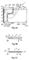
- the expressions “upward flow” and “downward flow” in the following description are based on the direction of the air flow when the air passage is open as shown in Fig. 1(B) , and expressions indicating up, down, left and right relate to the positional situation shown in Fig. 1(A) and Fig. 6 . Further, in expressions relating to "front” and “rear”, “front” indicates the upper side in the state shown in Figs. 1(B) and 1(C) , and “rear” indicates the lower side in these drawings.
- the deaeration valve 1 As shown in Fig. 1(A) , the deaeration valve 1 according to the present embodiment is open with respect to air flow f1 in one direction from the upper side to the lower side (see Fig. 1(B) ), and it is closed with respect to air flow f2 in the other direction from the lower side to the upper side (see Fig. 1(C) ).
- This deaeration valve 1 is principally attached to a compression bag 5 such as that shown in Fig. 6 , and is used in order to remove air in the storage section 62 of the compression bag 5. Equipping of this deaeration valve 1 is not limited to a compression bag as in the present embodiment, and it may also be applied to a bag that is used to be filled with gases such as air. Further, the deaeration valve 1 may also be used as a check valve for general fluids such as gases other than air and liquids such as water.
- the deaeration valve 1 comprises two valve films 11 and 12 of synthetic resin that are placed one on the other.
- these valve films 11 and 12 desirably, at least the surfaces forming the inner faces of the air passage 2 have weak contact property, thereby making the valve films 11 and 12 readily contact together.
- the valve films 11 and 12 used in the present embodiment have a rectangular shape as shown in Fig. 1 , but they may also have another shape.
- an air passage 2 is provided where air allows to pass through the valve films 11 and 12 from an inlet 2a to an outlet 2b, and it is closable by the valve films 11 and 12 that closely contact together.
- This air passage 2 is defined by the two seal sections 21, 22 formed by bonding the valve films 11 and 12 together.
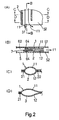
- the air passage 2 is constituted by the two valve films 11 and 12, but as shown in Fig. 5 , a structure may also be adopted in which an intermediate film 13 is disposed between the two valve films 11 and 12, wherein the base end side of the intermediate film 13 is bonded to the rear side valve film 12, as shown in Fig. 5(B) , and the front end side thereof is movable inside the air passage 2 and able to make a close contact to the front side valve film 11, as shown in Fig. 5(C) .
- the air passage 2 may have a structure to be closable by the intermediate film 13 and the front side valve film 11 that closely contact together, in addition to the close contact between the valve films 11 and 12 described above.
- the downward flow side edge of the intermediate film 13 is positioned further toward the upward flow side than the downward flow side edges 11b and 12b of the valve films 11 and 12, but it is also possible for the positions of the respective edges 11b, 12b and 13b to be aligned with each other.
- the opposing faces of the rear side valve film 12 and the intermediate film 13, which are separated except the base end section when the air passage 2 is closed, do not have a weak contact property in order to make the films 12 and 13 less liable to closely contact together.
- the aforementioned seal sections 21 and 22 comprise a first side seal section 21 which has a linear shape extending in the up/down direction in the figure, following the left-hand edge of the valve films 11, 12 in the figure, and a second side seal section 22 which is formed towards the right-hand side from the first side seal section 21 in the figure, and which extends in the up/down direction in the figure, but is formed in a bent fashion.
- the second side seal 22 in the present embodiment comprises three sections; an introduction section 221, an intermediate section 222 and an expulsion section 223, from the top downwards in the drawings.
- the introduction section 221 is disposed toward the inlet side of the air passage 2
- the expulsion section 223 is disposed toward the outlet side of the air passage 2.
- the upward flow side end 221a of the introduction section 221 and the upward flow side end 21a of the first side seal section 21 form the inlet 2a of the air passage.
- the inlet 2a is defined by the straight line which links the respective end sections 221a and 21a.
- the downward flow side end 223b of the expulsion section 223 and the downward flow side end 21b of the first side seal section 21 form the outlet 2b of the air passage.
- the outlet 2b is defined by the straight line which links the respective end sections 223b and 21b.
- the intermediate section 222 is connected between the introduction section 221 and the expulsion section 223.
- the intermediate section 222 is formed more closely to the first side seal section 21 than the introduction section 221
- the expulsion section 223 is formed more closely to the first side seal section 21 than the intermediate section 222.
- the dimension L2b between the respective end sections of the first side seal section 21 and the second side seal section 22 on the outlet side of the air passage is smaller than the dimension L2a between the respective end sections on the inlet side.
- the width of the air passage 2 in the present embodiment narrows toward the downward flow side.
- each of the introduction section 221, the intermediate section 222 and the expulsion section 223 is formed by straight lines, and as shown in Fig. 1 , the introduction section 221 and the expulsion section 223 are formed in parallel with the first side seal section 21.
- the mode of the seal sections 21 and 22 is not limited to that shown in the present embodiment, and it may be modified in various ways.
- first side seal section 21 is formed in a straight line and the second side seal section 22 is curved, but as shown in Fig. 7(D) , it is also possible to form both of the seal sections 21 and 22 in curved lines, in a laterally symmetrical configuration.
- a non-sealed section 3 is formed outside the air passage 2.
- This non-sealed section 3 consists of a passage extension section 31 and a free section 32.
- the passage extension section 31 is a portion located on the downward flow side from the outlet 2b of the air passage 2, and air that has passed through the air passage 2 continues to pass through this section.
- the free section 32 is a section in which the valve films 11 and 12 are closed by a unifying seal 64 formed when installing the valve on the compression bag 5, as shown in Fig. 6 , for example, and air does not pass through this section as it does through the air passage 2.
- the air flow into the air passage extension section 31 from the air passage 2 may pass through the free section 32.
- the passage extension section 31 in the deaeration valve 1 is a triangular-shaped portion defined by three lines; the outlet 2b, namely, the line linking the downward flow side end 21b [changed from 21a ] of the first side seal section 21 and the downward flow side end 223b of the expulsion section 223 of the second side seal section 22, the downward flow side edges 11b and 12b of the valve films 11 and 12, and the line of extension 223c of the second side seal 22 on the downward flow side of the expulsion section 223 of the second side seal 22 (indicated by a broken line).
- the valve films 11 and 12 can closely contact together in this passage extension section 31, as the valve films 11 and 12 in the air
- the first side seal 21 serves as a bone for the valve films 11 and 12 and prevents the valve films 11 and 12 from curling in the passage extension section 31, and hence there is no obstacle to close contact of the valve films 11 and 12 in the passage extension section 31.
- Figs. 7(A), 7(C) and 7(H) it is also possible to separate the downward flow side edges 11b and 12b of the valve films 11 and 12 from the downward flow side end 21a of the first side seal section 21, in such a manner that the respective seal sections 21 and 22, and the downward flow side edges 11b and 12b of the valve films 11 and 12 are not connected.
- the free section 32 is adjacent to both the air passage 2 and the passage extension section 21.
- the portion to the left-hand side of the downward flow side line of extension 223c of the expulsion section 223 of the second side seal 22 forms the passage extension section 31, while the portion to the right-hand side forms the free section 32.
- the passage extension section 31 and the free section 32 are connected, and distortion of the valve films 11 and 12 in the passage extension section 31 can be absorbed in the free section 32. Therefore, at least in the passage extension section 31, the tension of the valve films can be stabilized, consequently eliminating slackening or wrinkles, and the valve films 11 and 12 can be made reliably to closely contact together. Inverse flow of the air in the air passage 2 can be effectively prevented by locating the portion where the valve films 11 and 12 closely contact together in this way adjacent to the downward flow side of the air passage 2.
- the unifying seal 64 formed in installation to the compression bag 5, or for the seals formed separately from this in the free section 32 in order to prevent passage of air between the valve films 11 and 12, to be formed from the upward flow side edges 11a and 12a of the valve films 11 and 12 in the free section 32, up to the downward flow side end 223b of the expulsion section 223 of the second side seal 22, and a gap must be provided between these seals and the downward side edges 11b and 12b of the valve films 11 and 12.
- the non-sealed section 3 is a square portion defined by the four lines; the outlet 2b, namely, the line linking the downward flow side end 21a of the first side seal section 21 and the downward flow side end 223b of the second side seal section 22, the downward flow side edges 11b and 12b of the valve films 11 and 12, the downward flow side line of extension 21c of the first side seal 21 and the downward flow side line of extension 223c of the second side seal 22.
- the width of the air passage 2 is narrowed toward the downwards flow side, and the lateral dimension of the free section 32 is greater in the figure than the lateral dimension of the passage extension section 31 in Fig. 1(A) . More specifically, in the present embodiment, the lateral dimension of the passage extension section 31 is 10 mm in the figure, whereas the lateral dimension of the free section 32 is 70 mm in the figure.
- the free section 32 is formed larger than the passage extension section 31 in this way, the above-described absorption of distortion in the free section 32 is performed more effectively.
- Fig. 6 explained will be a state where a deaeration valve 1 is installed to the compression bag 5 described below.
- the cross-sectional views in Fig. 2 to Fig. 4 exaggerate the size in the vertical direction of the figure, compared to an actual size.
- the opening 61 is closed by the closing means 61a, and pressure is applied from outside the bag by rolling up the storage section 62 or doing like this.
- the air inside the storage section 62 forms an air flow f1 and passes through the air passage 2 of the deaeration valve 1, being expelled to the exterior of the bag.
- the valve films 11 and 12 are pushed forcibly apart as shown in Fig. 2(B) of an end view along B - B.
- the air flow f1 as shown by the arrow in Fig. 2(A) , also flows to the free section 32.
- FIG. 2(C) shows a sectional view along C - C in the lateral direction of the air passage 2 of the deaeration valve 1 in this case
- Fig. 2(D) shows a sectional view along D - D in the lateral direction of the passage extension section 31 and the free section 32 of the deaeration valve 1 in this case.
- FIGs. 3(A) and 3(B) show a momentary state when the aforementioned deaeration action has ended and the air flow f1 has ceased to pass through the air passage 2.
- the interior of the storage section 62 of the compression bag 5 assumes a state of negative pressure due to the expulsion of the air therein. Consequently, as shown in Fig. 3(B) of a sectional view along E - E, a force X acts on the valve films 11 and 12 so as to pull them towards the storage section 62, and hence the valve films 11 and 12 closely contact together. This close contact of the valve films 11 and 12 occurs within a very short period of time, and hence there is virtually no inverse flow of air through the air passage 2 during the movement of the valve films 11 and 12.
- Figs. 4(A) to 4(D) show the cases where the valve films 11 and 12 described above closely contact together, and the air passage 2 is closed.
- Fig. 4(B) of a sectional view along F - F the valve films 11 and 12 normally closely contact to each other, thus closing the air passage 2 completely, but as shown in Fig. 4(C) of a sectional view along G - G in the lateral direction of the air passage 2 of the deaeration valve 1, a gap Y may occasionally arise between the valve films 11 and 12 due to slackening of the valve films 11 and 12. This is because the valve films 11 and 12 are fixed by the first side seal section 21 and the second side seal section 22, and hence relative displacement between the valve films 11 and 12 is restricted.
- the second side seal section 22 is not present, and therefore the valve films 11 and 12 are able to move in the direction of arrow Z, as shown in Fig. 4(D) of a sectional view along H - H in the lateral direction of the air passage 2 of the deaeration valve 1. Consequently, it is possible to absorb any displacement between the valve films 11 and 12 in the free section 32, and therefore, no gaps Y such as that in Fig. 4(C) occur, and the valve films 11 and 12 can be made reliably to closely contact together in the passage extension section 31.
- valve films 11 and 12 closely contact together due to a force X that pulls them towards the storage section 62, but in addition to this, the intermediate film 13 and the front side valve film 11 closely contact together, as shown in Fig. 5(C) , due to the aforementioned force X (in order to aid understanding, the valve films 11 and 12 are depicted in a separated fashion in Fig. 5(C) ).
- a pocket-shaped space 2c may be provided between each of the valve films 11 and 12 and the intermediate film 13, but even in this case, the air flow f2 heading to flow inversely from the outlet 2b to the inlet 2a of the air passage 2 remains in this pocket-shaped space 2c and does not pass through the air passage 2.
- the dimension of the inlet 2a of the air passage 2 is large, since the air is guided smoothly into the air passage 2. Contrary to this, it is desirable that the dimension of the outlet 2b of the air passage 2 is small, since distortion is not liable to occur in the valve films 11 and 12. And, it is desirable that the dimension of the air passage 2 from the inlet 2a to the outlet 2b is large in order to ensure that the valve films 11 and 12 closely contact together in a reliable fashion.
- the dimensions of the respective sections of the deaeration valve 1 will be determined by taking things into consideration, because balancing the dimensions with the size of the compression bag 5 to which the valve is applied, or ensuring a large storage section 62 in the compression bag 5 are functionally required.
- the lateral dimension between the introduction section 221 and the first side seal section 21 in the vicinity of the inlet 2a of the air passage 2 is taken to be 20 mm - 60 mm. In the present embodiment, it is set as 30 mm. Further, desirably, the lateral dimension between the expulsion section 223 and the first side seal section 21 in the vicinity of the outlet 2b of the air passage 2 is taken to be 5 mm - 30 mm. In the present embodiment, it is set as 10 mm. Desirably, the dimension of the deaeration valve 1 in the vertical direction in the figure is 30 mm - 100 mm.
- the dimension falls on the upward flow side edge 12a and the downward flow side edge 12b of the rear side valve film, and is taken as 45 mm.
- the distance between the first side seal section 21 and the second side seal section 22 can be set freely, it is possible to design a deaeration valve 1 capable of passing the optimum amount of air through the air passage 2 in accordance with the size of the compression bag 5 to which the deaeration valve 1 is installed.
- the dimension of the deaeration valve 1 in the lateral direction in the figure is taken as 80 mm, and the free section 32 has a dimension sufficiently larger than the passage extension section 31, but depending on the circumstances, it is also possible to make the right-hand ends of the valve films 11 and 12 in the figure coincide with the introduction section 221 of the second side seal section 22, as shown in Fig. 7(G) , in such a manner that the free section 32 is formed solely between the expulsion section 223 of the second side seal section 22 and the right-hand ends of the valve films 11 and 12 in the figure.
- the upward flow side edge 11a of the front side valve film 11 and the upward flow side edge 12a of the rear side valve film 12, both of the valve films being placed one on the other, are disposed in staggered positions, displaced towards the upward flow side and the downward flow side.
- the upward flow side edge 11a of the front side valve film 11 is disposed towards the downward flow side.
- the aforementioned displacement is desirably set within the range of 1 mm to 10 mm, and more desirably, 3 mm to 5 mm. This displacement is not essential in the present invention, but is desirably to be provided. Also, this displacement may be called "step difference".
- the displacement between the edges 11a and 12a is provided in order to avoid the inlet 2a of the air passage 2 from being sealed due to dislocation of the unifying seal section 64 that is a heat seal formed between the deaeration valve 1 and each of the bag films 51 and 52 when bonding the deaeration valve 1 onto the bag films 51 and 52 as described hereinafter. Further, it also serves to make the valve films 11 and 12 readily open up during deaeration, in such a manner that the air flow f1 can be smoothly introduced to the air passage 2 during deaeration. In the present embodiment, as shown in Fig.
- the dimension of the valve films 11 and 12 in the vertical direction in the figure is the same in the sections where the air passage 2 is formed and the other sections of the films, but it is effective as long as a displacement as described above exists in the section where the air passage 2 is formed.
- An inert liquid 4 such as silicon oil, is at least partly disposed between the inner surfaces of the valve films 11 and 12.
- This liquid 4 due to its viscosity, has effects of reinforcing close contact between the valve films 11 and 12 when the air passage 2 is sealed.
- the viscosity of the liquid 4 has a low viscosity, since it is difficult to open up the air passage 2 if the viscosity is too high. However, even it is low, needed is the viscosity of a level that does not allow the liquid to leak out from the air passage 2.
- This compression bag 5 is formed with at least two bag films 51 and 52, which are made of synthetic resin and placed one on the other, by partly bonding the films together.
- the compression bag 5, as shown in Fig. 6 has a storage section 62 that includes an opening 61 and is able to contain an item such as clothing, and a deaeration opening 63 for removing air in the storage section 62 other than the opening 61.
- the opening 61 in the compression bag 5 according to the present embodiment, can be hermetically closed by a closing device, such as a fastener 61a, which closes by way of interlocking a recessed strip with a projecting zip.
- the deaeration openings 63 are provided on the lower side of the compression bag 5 in the figure.
- the opening 61 and the deaeration openings 63 can be positioned freely as long as they do not affect in the status where the deaeration valve 1 is attached, as described hereinafter.
- the number of deaeration openings 63 in the compression bag 5 according to the present embodiment, three deaeration openings 63 are provided, but this number may be varied.
- the bag films 51 and 52 according to the present embodiment have a rectangular shape in a plan view, but they may be also formed in a circular shape, a polygonal shape, or other forms variously.
- the aforementioned deaeration valve 1 is, between the storage section 62 and a deaeration opening 63, attached with the inlet side of the air passage 2 towards the top and the outlet side towards the bottom. In the present embodiment, it is positioned within a range of 60 mm from the bottom of the compression bag 5.
- the deaeration valve 1 is attached through forming an integral seal section 64 in which the valve films 11 and 12, and the bag films 51 and 52 are bonded together. Except the air passage 2, air does not flow between the storage section 62 and the deaeration opening 63 by forming this unifying seal section 64.
- elongate films are used as valve films 11 and 12, and a plurality of deaeration valves 1 are disposed parallel in the lengthwise direction of these valve films, in such a manner that air passages 2 and free sections 32 are respectively adjacent, as shown in Fig. 6 . Consequently, combined with similarly elongate bag films 51 and 52, compression bags 2 [ should be 5 ] can be continuously manufactured, resulting in enhancement of productive efficiency. Moreover, when a plurality of deaeration valves 1 are aligned in this fashion, the number of air passages 2 per compression bag 5 can be readily increased as the compression bag 5 becomes larger, especially extending the lateral dimension, and hence it is not difficult in deaeration with a large-size compression bags 5.
- Aforementioned unifying seal section 64 is formed by heat sealing. Therefore, a heat resistant coating 7 is provided at least on part of the inner surfaces of the valve films 11 and 12 in the air passage 2 of the deaeration valve 1, further coinciding with the unifying seal section, more specifically, as shown in Fig. 1(B) , in the vicinity of the inlet 2a of the air passage 2, in order that the air passage 2 is not closed off due to melting of the valve films 11 and 12 under the effects of the heat applied during heat sealing.
- heat resistant means a property whereby the material degenerates, by fusion, or the like, due to heat of the heat sealing operation, without affecting surrounding members, such as valve films 11 and 12.
- a heat resistant coating 7 is provided on the surface of the valve film 11 or the intermediate film 13 facing onto the space which is formed when the valve is opened and where the air flow f1 passes, specifically, on the surface adjacent to the inlet 2a of the air passage 2, as shown in Fig. 5(B) .
- the storage section 62 comprises an item storage portion 62a where an item is actually contained, and an air introduction portion 62b which lies between the item storage portion 62a and the deaeration valve 1, wherein valve protection seals 67 are formed at the boundary between these portions 62a and 62b.
- the valve protection seals 67 are intermittently formed by bonding the bag films 51 and 52 together. The interval at which the valve protection seals 67 are formed may be such that air is allowed to pass between the portions 62a and 62b and the seals do not affect the introduction of air into the air passages 2.
- each valve protection seal 67 is 10 mm in the left/right direction in the figure, and the interval between the valve protection seals 67 is 25 mm.
- the form of the valve protection seals 67 can be modified variously, however, it is desirable they have a form, for example, such as a circular form, which makes less resistance when air passes between the portions 62a and 62b.
- valve protection seals 67 Forming of the valve protection seals 67 in this way enables the item such as clothing contained in the item storage portion 62a to be prevented from being sucked into the air passages 2 by the air flows f1. And, even when stuffing of the item into the item storage portion 62a makes the bag films 51 and 52 curve, portions of the bag films 51 and 52, namely, the downward flow side films 51a and 52a situated in the air introduction portion 62b, do not follow the curving, achieving a non-deformed state. Consequently, it is possible for the deaeration valves 1 to maintain a flat state without being affected by the stuffed item, resulting in opening and closing the air passages 2 reliably. However, it is not essential to form these valve protection seals 67, and they may be omitted.
- a long film rolled up in the form of a roll is used for the valve films 11 and 12 according to the present embodiment. Specifically, a film having a width of 45 mm and a length of 1000 m is used.
- a heat resistant coating 7 is coated by means of gravure printing or the like onto part of the surface of the rear side valve film 12 facing the front side valve film 11, specifically, in the vicinity of the position where the inlet 2a of the air passage 2 is to be formed. The width dimension of the front side valve film 11 is then reduced by approximately 5 mm.
- This dimensional difference forms the above-described displacement of the edges 11a and 12a.
- Either of the valve films 11 and 12 is coated with silicon oil 4 onto the surface of the portion where an air passage 2 is to be formed. This coating operation may be performed by painting with a brush or the like, or by spraying.
- the two valve films 11 and 12 are then placed one on the other, and a first side seal section 21 and a second side seal section 22 are formed by heat sealing the films, as illustrated in Fig. 1(A) .
- the first side seal section 21 is formed throughout the whole width of the valve films 11 and 12 in this operation.
- the downward flow side end section 223b of the second side seal section 22 does not coincide with the downward flow side edges 11b and 12b of the valve films 11 and 12, thus providing a gap.
- This gap is the line of extension 223c of the seal section 22, which forms the boundary between the passage extension section 31 and the free section 32 described above.
- the deaeration valve 1 formed, as shown in Fig. 1(A) , in this way is sandwiched between the bag films 51 and 52, and the unifying seal section 64 is formed, thereby unifying the valve and the bag films.
- Side seal sections 65 are then formed on the perimeter edges of the bag films 51 and 52, except the portions where the opening 61 and the deaeration opening 63 are to be formed.
- a fastener 61a of a closing means is attached.
- a slider 8 is provided to aide opening and closing of the zip fastener 61a.
- the side seal sections 65 are not formed at the portion where the heat resistant coating 7 overlaps, thus heat sealing is ineffective, and hence air may leak.
- inner seal sections 66 are further formed to the inner side from the side seal sections 65 formed on the right and left-hand edges of the compression bag 5 in the figure.
- the deaeration valve 1 is sure to be bonded to the bag films 51 and 52 at the side seal section 65 and/or inner seal section 66, except the portion such as the free section 32 where the heat resistant coating 7 is provided.
- the deaeration valve 1 is not fixed to the bag films 51 and 52 at any positions other than the unifying seal section 64, the side seal sections 65 and the inner seal sections 66. Therefore, as described above, the free section 32 is hardly disturbed in absorbing distortion of the valve films 11 and 12 in the passage extension section 31.
- the present invention has the following beneficial effects.
- distortion in the valve films 11 and 12 in the passage extension section 31 can be eliminated, and therefore, at least in this passage extension section 31, the tension of the valve films can be stabilized, and the valve films 11 and 12 can be reliably made to closely contact together without slackening or wrinkles. Since the reliable portion of close contact like this between the valve films 11 and 12 is located adjacent to the outlet 2b of the air passage 2, it is possible to effectively prevent inverse flow of air in the air passage 2. Consequently, a deaeration valve that is capable of effective prevention of inverse air flow in spite of a simple structure is provided.
- a free section 32 which is a section adjacent to the passage extension section 31, or adjacent to the air passage 2 and the passage extension section 31, is formed, and the parts of the valve films 11 and 12 forming the passage extension section 31 and the free section 32 form a single body. Therefore, distortion of the valve films 11 and 12 in the 131 can be absorbed in the free section 32, whereby the tension in the valve films can be stabilized, at least in this passage extension section 31, and the valve films 11 and 12 can be reliably made to closely contact together without slackening or wrinkles.
- the dimension L2b between the respective end sections of the first side seal section 21 and the second side seal section 22 on the outlet side of the air passage 2 is made smaller than the dimension L2a between the respective end sections on the inlet side, and therefore it is possible to form the free section 32 to a larger size than the passage extension section 31, and a deaeration valve in which distortion is absorbed more effectively in the free section 32 is provided.
- the upward flow side edge 11a, 12a of the valve film 11, 12 on one side and the upward flow side edge 12a, 11a of the valve film 12, 11 on the other side are disposed in staggered positions, towards the upward flow side and the downward flow side respectively, and therefore, it is possible to prevent the inlet 2a of the air passage 2 from being bonded and closed off, when the deaeration valve 1 is bonded onto the bag films 51 and 52 that form the compression bag 5. Further, this also has the action of facilitating opening of the valve films 11 and 12 during deaeration, in such a manner that the air flow f1 is smoothly introduced into the air passage 2 during deaeration.
- an inert liquid 4 such as silicon oil is provided on at least part of the inner surfaces of the valve films 11 and 12 in the air passage 2, and therefore close contact between the valve films 11 and 12 with the air passage 2 closed can be reinforced by the viscosity of the liquid 4.
- a compression bag equipped with a deaeration valve capable of stabilizing tension of the valve films 11 and 12 and effective prevention of inverse air flow in spite of a simple structure, and since a heat resistant coating 7 is provided on at least part of the inner surfaces of the valve films 11 and 12 in the air passage 2 of the deaeration valve 1, then it is possible to provide a compression bag equipped with a deaeration valve in which the air passage 2 is not closed off as a result of melting of the valve films 11 and 12 due to the effects of heat during heat sealing for forming the compression bag 1.
- long films are used for the valve films 11 and 12, and a plurality of the aforementioned deaeration valves 1 are arranged in the lengthwise direction of the valve films 11 and 12 in such a manner that the respective air passages 2 and free sections 32 are adjacent, and therefore, combined with similarly elongate bag films 51 and 52, it is possible to continuously manufacture compression bags 2, resulting in enhancement of productive efficiency.
- valve protection seals 67 are formed at the boundary between an item storage portion 62a and an air introduction portion 62b, and therefore it is possible to provide a compression bag equipped with a deaeration valve capable of preventing the item such as clothing contained in the item storage portion 62a from being sucked into the air passage 2. Further, even when the bag films 51 and 52 are caused to curve when an item is stuffed into the item storage portion 62a, the portions of the bag films 51 and 52 located in the air introduction portion 62b do not curve accordingly, and can be maintained in a non-deformed state.
Landscapes
- Engineering & Computer Science (AREA)
- Mechanical Engineering (AREA)
- Bag Frames (AREA)
- Self-Closing Valves And Venting Or Aerating Valves (AREA)
- Check Valves (AREA)
Applications Claiming Priority (1)
| Application Number | Priority Date | Filing Date | Title |
|---|---|---|---|
| PCT/JP2005/016089 WO2007029292A1 (ja) | 2005-09-02 | 2005-09-02 | 脱気弁及びこの脱気弁を備えた圧縮袋 |
Publications (1)
| Publication Number | Publication Date |
|---|---|
| EP1930247A1 true EP1930247A1 (de) | 2008-06-11 |
Family
ID=37835429
Family Applications (1)
| Application Number | Title | Priority Date | Filing Date |
|---|---|---|---|
| EP20050776971 Withdrawn EP1930247A1 (de) | 2005-09-02 | 2005-09-02 | Entlüftungsventil und kompressionsbeutel mit dem entlüftungsventil |
Country Status (5)
| Country | Link |
|---|---|
| US (1) | US7708464B2 (de) |
| EP (1) | EP1930247A1 (de) |
| JP (1) | JP4792035B2 (de) |
| CN (1) | CN1934382B (de) |
| WO (1) | WO2007029292A1 (de) |
Cited By (2)
| Publication number | Priority date | Publication date | Assignee | Title |
|---|---|---|---|---|
| EP2103540A3 (de) * | 2008-03-21 | 2011-03-02 | Chieh Hua Liao | Entlüftbarer Aufbewahrungsbeutel mit mehreren Luftaustrittslöchern |
| TWI413608B (zh) * | 2011-06-08 | 2013-11-01 | Yaw Shin Liao | Can be a number of gas filling structure |
Families Citing this family (17)
| Publication number | Priority date | Publication date | Assignee | Title |
|---|---|---|---|---|
| US8419278B2 (en) * | 2005-09-02 | 2013-04-16 | Mikio Tanaka | Check valve and compression bag and air cushion bag equipped therewith |
| ITMI20070175U1 (it) * | 2006-05-13 | 2007-11-14 | Haver & Boecker Ohg | Confezione |
| US8328421B2 (en) * | 2008-01-30 | 2012-12-11 | S.C. Johnson & Son, Inc. | Push-down compressible pouch with one-way valves on sides |
| JP4436925B1 (ja) * | 2009-10-30 | 2010-03-24 | 株式会社アシスト | 逆止弁及び密封袋、及び逆止弁と密封袋の製造方法 |
| KR101228514B1 (ko) * | 2010-03-08 | 2013-02-01 | 미키오 다나카 | 역지밸브 및 그 역지밸브를 구비한 압축주머니 및 에어완충주머니 |
| US8961014B2 (en) * | 2010-10-22 | 2015-02-24 | S.C. Johnson & Son, Inc. | Compressible pouch with multiple collapsible channels across bottom |
| CN102406271B (zh) * | 2011-11-02 | 2016-05-25 | 周艳春 | 具有双袋组合单向气阀的通风鞋 |
| CN105662011A (zh) * | 2012-03-06 | 2016-06-15 | 上海艾尔贝包装科技发展有限公司 | 一种充气垫 |
| CN102689743B (zh) * | 2012-03-06 | 2015-08-26 | 上海艾尔贝包装科技发展有限公司 | 自粘膜止回阀和空气包装装置 |
| US9725066B2 (en) * | 2013-05-04 | 2017-08-08 | Shanghai Air-Paq Composite Material Co., Ltd | Air bag packaging arrangement and self-adhesive checking valve |
| CN104783559B (zh) * | 2014-01-19 | 2018-06-19 | 上海艾尔贝包装科技发展有限公司 | 一种充气垫及其制造方法 |
| CN206068499U (zh) * | 2015-05-22 | 2017-04-05 | 聂会平 | 空气缓冲体的充气装置 |
| JP6664901B2 (ja) * | 2015-08-04 | 2020-03-13 | 株式会社ヤマモン | 弁構造と収納袋及びフィルム弁 |
| US10266330B2 (en) | 2017-02-14 | 2019-04-23 | Misumaru Sangyo Co., Ltd. | Compression bag and deflation valve for use therewith |
| JP6986268B2 (ja) * | 2018-04-26 | 2021-12-22 | 株式会社ヤマモン | フィルム弁及び収納袋 |
| CN109027334B (zh) * | 2018-06-27 | 2022-09-06 | 上海鹏型精密模具科技有限公司 | 一种防水透气塞 |
| CN109502162B (zh) * | 2018-11-21 | 2024-09-06 | 广东太力科技集团股份有限公司 | 一种用于真空压缩袋上的单向排气通道 |
Family Cites Families (20)
| Publication number | Priority date | Publication date | Assignee | Title |
|---|---|---|---|---|
| US2799314A (en) * | 1951-09-07 | 1957-07-16 | Dreyer Andre | Leak-proof containers for liquids |
| US2800269A (en) * | 1954-03-09 | 1957-07-23 | Milprint Inc | Valved bag |
| GB1016122A (en) * | 1963-02-15 | 1966-01-05 | Mogens Wilsbech | A method of forming a cross bottom at the end of a flat tubular blank of heat sealable material and bag having a cross bottom so made |
| US3263903A (en) * | 1964-05-21 | 1966-08-02 | Waller Lindquist Inc | Valved container |
| US3806025A (en) * | 1970-10-19 | 1974-04-23 | T Marshall | Stemming bag |
| JPS58112955A (ja) * | 1981-12-12 | 1983-07-05 | 高浦 潔 | 逆止弁つき袋体 |
| US4834554A (en) * | 1987-11-16 | 1989-05-30 | J. C. Brock Corp. | Plastic bag with integral venting structure |
| GB2213126B (en) * | 1987-12-04 | 1991-11-20 | S P Chemical Kabushiki Kaisha | Water holders |
| JPH06697Y2 (ja) | 1990-03-14 | 1994-01-05 | 株式会社柏原製袋 | 逆止弁 |
| JP3229729B2 (ja) * | 1993-09-21 | 2001-11-19 | ニコノス株式会社 | 逆止弁構造付き封入体およびその製造方法 |
| US5540500A (en) * | 1994-04-25 | 1996-07-30 | Nichimen Corporation | Compressive sealed bag for compressible articles such as clothing and the same |
| KR100371671B1 (ko) * | 1994-05-17 | 2003-05-17 | 이데미쓰세끼유가가꾸가부시끼가이샤 | 스냅이부착된자루 |
| JPH09290840A (ja) * | 1996-04-24 | 1997-11-11 | Seisan Nipponsha Kk | 逆止弁付合成樹脂製袋体 |
| JP2880128B2 (ja) * | 1996-05-23 | 1999-04-05 | 錦商事株式会社 | 逆止弁 |
| JPH10706A (ja) * | 1996-06-14 | 1998-01-06 | Seisan Nipponsha Kk | 逆止弁付合成樹脂製袋体の製造方法 |
| JP3563024B2 (ja) * | 2000-10-12 | 2004-09-08 | 株式会社柏原製袋 | 圧縮袋 |
| JP2002193273A (ja) * | 2000-12-22 | 2002-07-10 | R:Kk | 圧縮収納袋 |
| CN2466063Y (zh) * | 2001-03-06 | 2001-12-19 | 陈莉嘉 | 自密封薄膜袋 |
| EP1535851A4 (de) * | 2002-09-04 | 2009-04-29 | Ishizaki Shizai Kk | Druckaufnahmebeutel mit r ckschlagventilfunktion |
| JP3677515B1 (ja) * | 2004-01-10 | 2005-08-03 | 株式会社アール | 圧縮袋の製造方法及び圧縮袋及び空気通路の構造 |
-
2005
- 2005-09-02 WO PCT/JP2005/016089 patent/WO2007029292A1/ja not_active Ceased
- 2005-09-02 JP JP2007534195A patent/JP4792035B2/ja not_active Expired - Fee Related
- 2005-09-02 EP EP20050776971 patent/EP1930247A1/de not_active Withdrawn
- 2005-09-02 CN CN2005800088153A patent/CN1934382B/zh not_active Expired - Fee Related
- 2005-09-02 US US10/571,899 patent/US7708464B2/en active Active
Non-Patent Citations (1)
| Title |
|---|
| See references of WO2007029292A1 * |
Cited By (2)
| Publication number | Priority date | Publication date | Assignee | Title |
|---|---|---|---|---|
| EP2103540A3 (de) * | 2008-03-21 | 2011-03-02 | Chieh Hua Liao | Entlüftbarer Aufbewahrungsbeutel mit mehreren Luftaustrittslöchern |
| TWI413608B (zh) * | 2011-06-08 | 2013-11-01 | Yaw Shin Liao | Can be a number of gas filling structure |
Also Published As
| Publication number | Publication date |
|---|---|
| JPWO2007029292A1 (ja) | 2009-03-12 |
| JP4792035B2 (ja) | 2011-10-12 |
| CN1934382B (zh) | 2011-05-04 |
| WO2007029292A1 (ja) | 2007-03-15 |
| US7708464B2 (en) | 2010-05-04 |
| US20080253698A1 (en) | 2008-10-16 |
| CN1934382A (zh) | 2007-03-21 |
Similar Documents
| Publication | Publication Date | Title |
|---|---|---|
| EP1930247A1 (de) | Entlüftungsventil und kompressionsbeutel mit dem entlüftungsventil | |
| US8419278B2 (en) | Check valve and compression bag and air cushion bag equipped therewith | |
| EP3258147B1 (de) | Rückschlagventile | |
| US8404115B2 (en) | Sealed filter element | |
| US20100291852A1 (en) | Outflow valve for an aircraft | |
| CA2562665A1 (en) | Ventable interlocking closure strip | |
| JP2009532278A5 (de) | ||
| CN111439484A (zh) | 气柱袋及其缓冲气柱用气道 | |
| KR102178798B1 (ko) | 다이어프램 밸브 | |
| CN105078268B (zh) | 一种蒸汽口密封圈及其安装结构 | |
| DE202006016789U1 (de) | Anschlussstück für einen Staubfilterbeutel sowie mit einem solchen Anschlussstück ausgestatteter Staubfilterbeutel | |
| WO2012090337A1 (ja) | 逆止弁及びこれを備えた収納体 | |
| ITMI20072079A1 (it) | Valvola con una zona di tenuta in vetro metallico | |
| CN109477542A (zh) | 液压阻尼支承 | |
| US11105434B2 (en) | Flow rib in valves | |
| CN101978199A (zh) | 最大压力液压阀 | |
| DE202010014870U1 (de) | Strömungskanal für ein Klimagerät | |
| DE10023455C2 (de) | Druckventil für einen Verdichter | |
| EP4617491A1 (de) | Mikropumpe mit verbesserten ventilen | |
| CN107228191B (zh) | 传动系统控制板和传动控制系统 | |
| CN111664248A (zh) | 一种桥式吸砂机渠道往复式密封装置 | |
| DE102012103455A1 (de) | Ventil- und Felgenbandanordnung | |
| CN2761934Y (zh) | 单向止回电磁阀 | |
| CN209430022U (zh) | 铝合金窗的排水结构 | |
| CN100427312C (zh) | 事务机及其喷墨卡匣密闭装置 |
Legal Events
| Date | Code | Title | Description |
|---|---|---|---|
| PUAI | Public reference made under article 153(3) epc to a published international application that has entered the european phase |
Free format text: ORIGINAL CODE: 0009012 |
|
| 17P | Request for examination filed |
Effective date: 20080401 |
|
| AK | Designated contracting states |
Kind code of ref document: A1 Designated state(s): DE FR GB |
|
| RBV | Designated contracting states (corrected) |
Designated state(s): DE FR GB |
|
| STAA | Information on the status of an ep patent application or granted ep patent |
Free format text: STATUS: THE APPLICATION HAS BEEN WITHDRAWN |
|
| 18W | Application withdrawn |
Effective date: 20090910 |