EP1948497B1 - Lenkeinrichtung - Google Patents
Lenkeinrichtung Download PDFInfo
- Publication number
- EP1948497B1 EP1948497B1 EP05813650.8A EP05813650A EP1948497B1 EP 1948497 B1 EP1948497 B1 EP 1948497B1 EP 05813650 A EP05813650 A EP 05813650A EP 1948497 B1 EP1948497 B1 EP 1948497B1
- Authority
- EP
- European Patent Office
- Prior art keywords
- steering
- steering device
- support structure
- crown
- handgrips
- Prior art date
- Legal status (The legal status is an assumption and is not a legal conclusion. Google has not performed a legal analysis and makes no representation as to the accuracy of the status listed.)
- Expired - Lifetime
Links
Images




Classifications
-
- B—PERFORMING OPERATIONS; TRANSPORTING
- B62—LAND VEHICLES FOR TRAVELLING OTHERWISE THAN ON RAILS
- B62D—MOTOR VEHICLES; TRAILERS
- B62D1/00—Steering controls, i.e. means for initiating a change of direction of the vehicle
- B62D1/02—Steering controls, i.e. means for initiating a change of direction of the vehicle vehicle-mounted
- B62D1/04—Hand wheels
- B62D1/06—Rims, e.g. with heating means; Rim covers
-
- B—PERFORMING OPERATIONS; TRANSPORTING
- B62—LAND VEHICLES FOR TRAVELLING OTHERWISE THAN ON RAILS
- B62D—MOTOR VEHICLES; TRAILERS
- B62D1/00—Steering controls, i.e. means for initiating a change of direction of the vehicle
- B62D1/02—Steering controls, i.e. means for initiating a change of direction of the vehicle vehicle-mounted
- B62D1/04—Hand wheels
-
- Y—GENERAL TAGGING OF NEW TECHNOLOGICAL DEVELOPMENTS; GENERAL TAGGING OF CROSS-SECTIONAL TECHNOLOGIES SPANNING OVER SEVERAL SECTIONS OF THE IPC; TECHNICAL SUBJECTS COVERED BY FORMER USPC CROSS-REFERENCE ART COLLECTIONS [XRACs] AND DIGESTS
- Y10—TECHNICAL SUBJECTS COVERED BY FORMER USPC
- Y10T—TECHNICAL SUBJECTS COVERED BY FORMER US CLASSIFICATION
- Y10T74/00—Machine element or mechanism
- Y10T74/20—Control lever and linkage systems
- Y10T74/20576—Elements
- Y10T74/20732—Handles
- Y10T74/20834—Hand wheels
- Y10T74/20864—Handles
Definitions
- the invention discloses a steering device particularly usable, but not exclusively, for motor vehicles and the following description has been made referring to this field of application only with the purpose to make the description easier.
- the device is usable also for trolley vehicles, farm machinery, public works vehicles, motor boats, amphibious vehicles, and the like or for any vehicle allowing a movement even if not rectilinear.
- the steering control has always been transmitted from a steering device, usually known as a "steering wheel” fixed on a central hub and connected, by means of a steering column, to steering mechanisms controlling the directioning position of the front wheels.
- a steering device usually known as a "steering wheel” fixed on a central hub and connected, by means of a steering column, to steering mechanisms controlling the directioning position of the front wheels.
- the steering wheels have been modified and improved in design, ergonomics, adjustment etc.
- steering wheels which are adjustable in height and inclination, made of different materials, stronger and, at the same time, of lighter weight, steering wheels that are able to absorb shocks, thanks to modification to the steering column, or more simply, equipped with instantaneously inflatable cushions (called airbags) to protect the driver in case of collision.
- airbags instantaneously inflatable cushions
- the shape of the steering wheels has changed, in some cases, as for example in "Formula One", in which steering wheels of semicircular shaped and extractable from the driver have been used, to satisfy more restrictive space needs, during the driving and upon getting in and out of the vehicle.
- the steering control is applied by the driver of the vehicle to the steering wheel; safety rules and highway code require the driver to hold the steering wheel with both hands, while driving, in order to have a better control of the vehicle.
- driving conditions for example in reverse motion, or in U-turn, it is uncomfortable to keep both hands onto the steering wheel; during reverse motion, the position of the driver is unnatural in comparison with the normal driving position, the driver being partially or totally turned backwards, thereby he tends to detach one hand from the steering wheel.
- US-A-3 312 123 describes a tiltable steering assembly for a motor vehicle, comprising fixed support means, a first pair of essentially parallel shafts rotatably mounted in the fixed support means, a second pair of essentially parallel shafts each pivotally secured to one of the first pair of shafts, vehicle operator grip means fixed to each of the second shafts for rotation thereof and therewith, means pivotally secured to the first support means and rotatably supporting the second shafts whereby tilting movement of the second support means relative to the first support means effects a simultaneous tilting movement of the second shafts, and torque transfer means interconnecting the first shafts to each other and adapted to be connected to a teering shaft of the vehicle to thereby provide simultaneously rotation of all the shafts upon rotation of one of the shafts.
- US-A-3 176 537 describes a vehicle steering system comprising support means, a console device providing a rest for the arms and hands of an individual operator, means mounting the console device on the support means, an instrument of vehicle control unrelated to the steering function mounted on the console device, a steering shaft extending to the console device, and manually manipulated steering means mounted on the console device and being manipulable under operator finger action while the operator's arms and hands are at rest on said console device, the steering means being operably connected to the steering shaft.
- JP 11 342849 A describes a steering handle for vehicle comprising a handle main body fixed to a steering shaft and a pair of grips supported rotatable around the axial lines which are extended parallel with the steering shaft at both the left end and the tight end of the handle main body.
- a brake lever is provided to the right side grip. The steering handle can be rotated 180° to the left direction and the right direction respectively.
- JP 2004 175217 A describes a steering input device comprising an arm which is turned around a rotational axis at a centre portion. Grips are relatively rotatably held on both end portions of the arm and the rotation portions of the grips are defined by link members, respectively. Grip angle is set to be equal or greater than 30° and smaller or equal to 60°, the grip angle being an angle between the grips and straight lines parallel to the central line.
- JP 062122865 describes, a steering handle for automobile according to the preamble of claim 1 comprising a steering arm which provided at its central part with a boss. A taper serration is cut at the central part of the boss. The serration is fitted in a steering shaft to secure the boss to the shaft.
- the arm is provided at both ends with annular parts and a handling is engaged with the annular part.
- the handle is formed with an outer ring part, fitted in the annular part, and a grip part.
- US1714155 describes a steering wheel comprising a frame adapted for attachment to a steering column, consisting of two lobes placed on opposite sides of the steering column, a hand hold located within each lobe rotatably, each hand hold having a grip thereon for the hand.
- US2737060 describes a steering device comprising a hub, transverse members extending laterally from said hub terminating in annular grip rings at the outer ends thereof, ad annular inwardly facing channel shaped ball race formed in the inner periphery of the hand grip rings, a pair of oppositely disposed T-shaped metal arms each having the head thereof curved to conform to the radius of the ball race and having a plurality of ball retained notches therein, a ball in each of the notches, top and bottom hand grip elements covering the stems of the T-shaped metal arms and the hand grip elements together to form an integral hand grip freely turnably in each annular hand grip ring.
- the purpose of the present invention is to provide a steering device having structural and functional features to overcome the above described drawbacks.
- a particular purpose of the present invention is thus to guarantee greater driving safety, to reduce the effort needed for the steering control and to reduce the stress on the arms and the shoulders during the steering.
- a steering device comprising: a support structure in turn comprising a central hole for the fixing onto a steering column , the support structure being rotatable together with the steering column to operate steering mechanisms, and two mobile handgrips connected to the support structure and placed in distal positions with respect to the central hole, wherein the two mobile handgrips are simultaneously and freely rotatable, in a range from 0° to 360°, around an axis substantially orthogonal to the lying and rotating plane of the support structure so as to manually impart a rotating motion, around the steering column axis, to the support structure, characterized in that each mobile handgrip has a first end rotatably associated to the support structure and a free second end suitable for being gripped by a hand.
- the device comprises two mobile handgrips, fastened to said support structure in symmetrical positions with respect to the mid-plane of the support structure, said handgrips being shaped for the normal grip by the two hands of the driver.
- Figure 9 is a plan view of an adjustable spoke usable with a staring device of the preceding figures.
- a steering device can be in a position that we define as "central”, namely that allows the motion of the vehicle in a rectilinear direction, or in a position that we will define as “rotated”, namely reached through a steering control.
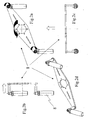
- the steering device comprises a support structure 2 integrally built by two spokes 3a and 3b with a central hole 4, for the fastening on a steering column (not shown in the figure); all is shown in detail in Figures 1a, 1c and 1d .
- the central hole 4 fits the steering column, permitting the fixing of the support structure 2 to the steering column itself; the latter is responsible of the transmission of the rotation of the steering device 1 to mechanisms controlling the change of the motion direction of the vehicle, by operating on directional members, such as wheels, tracks, rudders or the like.
- Two pivots 6a, 6b are fastened at the ends of the spokes 3a, 3b, in distal positions with respect to the central hole 4, each pivot being rotatable around an axis perpendicular to the plane of the related spoke.
- a handgrip 7a, 7b is secured at the free end of each pivot, it being substantially shaped as a twist grip, lying on a plane substantially perpendicular to the axis of the respective pivot 6a, 6b and consequently substantially parallel to the plane of the support structure 2.
- the support structure 2 and the twist grips 7 are mechanically connected by means of the pivots 6a, 6b, but are not tied to each other in their respective rotations, being able to rotate on two parallel planes respectively around the steering column and the axes of the pivots 6a, 6b, and being fixed to the support structure in symmetrical positions with respect to the mid-plane A-A.
- the twist grips 7, although following the rotation of the support structure 2 around the column, are also themselves rotatable around the axes of the pivots 6a, 6b, by an angle different from the angle of the rotation of the support structure 2 around the axis of the steering column, as well therewith.
- the two twist grips 7, being not tied in their respective rotations around the axes of the pivots 6a, 6b, can also be rotated by angles of amplitude different from each other.
- the torsion angle of the arms used for the steering control has amplitude of the same angle ⁇ ; as the arms reach the limit of their torsion capacity, they get asynchronously detached from the steering wheel to take the initial position again and complete the steering control action.
- the torsion angle of the arms used for the steering control is near zero.
- the twist grips 7 can be rotated in an opposite direction with respect to the rotation of the support structure 2, thus balancing the torsion of the arms around the column, i.e. since the rotation of the support structure and the torsion of the arms are equal and opposite, the resultant force is zero.
- the steering control is mainly applied by means of the forearms, carrying out a work of negligible entity. Consequently, the steering is more convenient and also quicker both in everyday driving and in the particular case of driving under non conventional conditions, such as rallies, road races, track races or the like, where the steering readyness is a critical factor and the advantage of the use of the steering device according to the invention is even more evident.
- the present invention allows the extraction of the twist grips 7 from the support structure 2, when the vehicle is stopped, to prevent an unauthorised use of the vehicle.
- the support structure 2 may comprise more than one spokes; as an alternative, it can also be designed without the spokes 3, for example shaped as a disk extending from the central hole 4 for the fastening to the steering column.
- the spokes 3 can be of the type shown in figure 9 ; in this case the angle between them is adjustable, because the spokes fit the hub or the steering column, by means of seats 120, in a position determined beforehand and not variable during the driving.
- the angle or the number of spokes complies with the particular safety and comfort requirements for the driver.
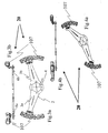
- handgrips consist of two crown segments of a normal steering wheel, possibly having imprints for the abutment of the fingers.
- the steering device 20 can thus be grasped in a more comfortable way in comparison with the basic embodiment.
- a third embodiment of the present invention is shown in two different operating positions, in which in order to, to identify parts equal or similar to those in the group of Figures 1a - 1d , the same reference numbers already used will be used, and to indicate modified parts, reference numbers increased by 200 will be used.
- handgrips are made of two reversed "cow horns" 207 possibly having imprints for the abutment of the fingers.
- the pivot 6a, 6b is preferably fixed in an adjustable position within a slot 210 of it's the corresponding spoke 3a, 3b; as an alternative, the slot can be formed on the handgrip 207; this permits the placing of the handgrips following the shape of one of the two slots and considering the particular needs of the driver.
- the said slots can be present also in the other embodiments of the present invention.
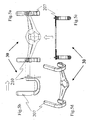
- a steering device 40 is shown, in different views, in a central position with handgrips 307 of the reversed "cow horns" type; in this embodiment, the steering device 40 has two crown segments, the first one 11 upwardly and the second on 12 downwardly.
- the two segments are fixed to the hub by means of respective spokes 13 and 14 and rotate therewith owing to a steering control applied to the steering device 40.
- the driver can take advantage of the shape of a traditional steering wheel for abutting his hands during long rectilinear ways.
- the handgrips can be made with the shapes of the previous embodiments, in particular that of figure 5 , thus maintaining the shape of the traditional steering wheel.
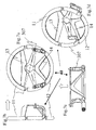
- FIGs 8a -8d a steering device 50 is shown, in different views, in a central position with handgrips 307 of the reversed "cow horns" type; in this embodiment, the steering device 50 is provided with a lower segment of crown 112.
- the segment is fixed to the hub by means of a spoke 114 and rotates therewith upon a steering control is applied to the steering device 50.
- a very important feature of the present invention is that, as shown in Figures 8a-8d , it is possible to omit, at least partially or also totally, the crown of the traditional steering wheel, thus preventing to place the airbag for the driver not necessary on the steering wheel, but also on the dashboard in front of the driving position, namely using the same arrangement that, for example, is provided for the passenger.
- Such a positioning of the airbag leads to the insertion, also after the purchase of a vehicle, of the steering device that is easy adaptable, by merely modifying or changing the hub assembled in the current production.
- the visibility of the instrument system can be notably improved, to the advantage of the driving safety and comfort.
- the configuration of the steering device can be flat or of cup-shaped type, or of any other known type.
Landscapes
- Engineering & Computer Science (AREA)
- Chemical & Material Sciences (AREA)
- Combustion & Propulsion (AREA)
- Transportation (AREA)
- Mechanical Engineering (AREA)
- Steering Controls (AREA)
- Air Bags (AREA)
- Mechanical Control Devices (AREA)
Claims (14)
- Lenkvorrichtung (1, 20, 30, 40, 50) umfassend:- eine Stützkonstruktion (2), welche wiederum ein zentrales Loch (4) zum Anbringen auf einer Lenksäule umfasst, wobei die Stützkonstruktion (2) gemeinsam mit der Lenksäule drehbar ist, um Lenkmechanismen zu steuern;- zwei bewegbare Handgriffe (7, 107, 207, 307), welche mit der Stützkonstruktion (2) verbunden sind und in distalen Positionen bezüglich des zentralen Lochs (4) angeordnet sind,wobei die zwei bewegbare Handgriffe (7, 107, 207, 307) gleichzeitig und frei, in einem Bereich von 0° bis 360°, um eine Achse, welche im Wesentlichen orthogonal zu der liegenden und sich drehenden Ebene der Stützkonstruktion (2) ist, drehbar sind, um die Stützkonstruktion (2) manuell in eine Drehbewegung um die Achse der Lenksäule zu versetzen,
dadurch gekennzeichnet, dass jeder der zwei bewegbaren Handgriffe (7, 107, 207, 307) ein erstes Ende, welches drehbar mit der Stützkonstruktion (2) verbunden ist, und gegenüberliegend zu dem ersten Ende ein freies zweites Ende aufweist, welche von einer Hand greifbar sind. - Lenkvorrichtung (1, 20, 30, 40, 50) nach Anspruch 1, wobei die zwei bewegbaren Handgriffe (7, 107, 207, 307) mittels Drehpunkten (6a, 6b) drehbar mit der Stützkonstruktion (2) verbunden sind, welche an entsprechenden Speichen (3a, 3b) der Stützkonstruktion (2) befestigt sind und jeder der Drehpunkte (6a, 6b) um seine Achse drehbar ist.
- Lenkvorrichtung (1, 20, 30, 40, 50) nach Anspruch 2, wobei die Speichen (3a, 3b) annehmbar mit der Stützkonstruktion (2) verbunden sind.
- Lenkvorrichtung (1, 20, 30, 40, 50) nach Anspruch 2, wobei jede Speiche (3a, 3b) auf der Lenksäule montiert ist und Befestigungsflächen (120) zum Einstellen eines Winkels zwischen den Speichen (3a, 3b) aufweist.
- Lenkvorrichtung (1, 20, 30, 40, 50) nach Anspruch 2, wobei die Drehpunkte (6a, 6b) an einer verstellbaren Position in Schlitzen (210) befestigt sind.
- Lenkvorrichtung (1, 20, 30, 40, 50) nach Anspruch 5, wobei die Schlitze (210) auf den Speichen (3a, 3b) ausgebildet sind.
- Lenkvorrichtung (1, 20, 30, 40, 50) nach Anspruch 5, wobei die Schlitze (210) auf den bewegbaren Handgriffen (7, 107, 207, 307) ausgebildet sind.
- Lenkvorrichtung (1, 20, 30, 40, 50) nach einem der vorhergehenden Ansprüche, wobei die bewegbaren Handgriffe (7, 107, 207, 307) an der Stützkonstruktion (2) in symmetrischen Positionen bezüglich einer Mittelebene (A-A) der Stützkonstruktion (2) befestigt sind, wobei die zwei bewegbaren Handgriffe (7, 107, 207, 307) für den normalen Griff von den zwei Händen des Fahrers geformt sind.
- Lenkvorrichtung (1) nach Anspruch 8, wobei die zwei bewegbaren Handgriffe (7, 107, 207, 307) Drehgriffe (7) sind.
- Lenkvorrichtung (20) nach Anspruch 8, wobei die zwei bewegbaren Handgriffe (7, 107, 207, 307) Kranzsegmente (107) sind.
- Lenkvorrichtung (30) nach Anspruch 8, wobei die zwei bewegbaren Handgriffe (7, 107, 207, 307) büffelhornartig (207) sind.
- Lenkvorrichtung (40) nach einem der Ansprüche 8 bis 11, ferner umfassend ein oberes Kranzsegment (11) und ein unteres Kranzsegment (12) befestigt an der Lenksäule mittels entsprechend weiterer Speichen (13, 14), wobei das obere Kranzsegment (11) und das untere Kranzsegment (12) gemeinsam mit der Stützkonstruktion (2) drehbar sind, wenn eine Lenkbetätigung an der Lenkvorrichtung (40) erfolgt.
- Lenkvorrichtung (50) nach einem der Ansprüche 8 bis 11, umfassend ein unteres Kranzsegment (112) befestigt an der Lenksäule mittels einer noch weiteren Speiche (114), wobei das untere Kranzsegment (112) gemeinsam mit der Stützkonstruktion (2) drehbar ist, wenn eine Lenkbetätigung an der Lenkvorrichtung (50) vorgenommen wird, wobei das untere Kranzsegment (112) dazu ausgebildet ist, einen Teil des Armaturenbretts zugänglich zu machen.
- Lenkvorrichtung (1, 20, 30, 40, 50) nach Anspruch 1, wobei die zwei bewegbaren Handgriffe (7, 107, 207, 307) mit handbetätigten Mitteln zusammengebaut werden.
Applications Claiming Priority (1)
| Application Number | Priority Date | Filing Date | Title |
|---|---|---|---|
| PCT/IT2005/000597 WO2007043072A1 (en) | 2005-10-12 | 2005-10-12 | Steering device |
Publications (2)
| Publication Number | Publication Date |
|---|---|
| EP1948497A1 EP1948497A1 (de) | 2008-07-30 |
| EP1948497B1 true EP1948497B1 (de) | 2013-07-03 |
Family
ID=35583425
Family Applications (1)
| Application Number | Title | Priority Date | Filing Date |
|---|---|---|---|
| EP05813650.8A Expired - Lifetime EP1948497B1 (de) | 2005-10-12 | 2005-10-12 | Lenkeinrichtung |
Country Status (7)
| Country | Link |
|---|---|
| US (1) | US9168943B2 (de) |
| EP (1) | EP1948497B1 (de) |
| JP (1) | JP5087001B2 (de) |
| CN (1) | CN101287636B (de) |
| CA (1) | CA2625246C (de) |
| ES (1) | ES2426995T3 (de) |
| WO (1) | WO2007043072A1 (de) |
Families Citing this family (15)
| Publication number | Priority date | Publication date | Assignee | Title |
|---|---|---|---|---|
| ITBO20070595A1 (it) * | 2007-08-29 | 2009-02-28 | Ferrari Spa | Airbag frontale per un veicolo stradale |
| CN105197092A (zh) * | 2015-09-07 | 2015-12-30 | 芜湖仅一机械有限公司 | 方向盘 |
| JP6581868B2 (ja) * | 2015-09-30 | 2019-09-25 | 株式会社Subaru | 車両用操舵ハンドル |
| JP6300383B2 (ja) * | 2016-06-23 | 2018-03-28 | 本田技研工業株式会社 | 車両用ステアリングホイール |
| EP3292035B1 (de) * | 2016-07-05 | 2018-09-05 | Yoav Netzer | Kompakte lenkung |
| JP2018144741A (ja) * | 2017-03-08 | 2018-09-20 | ヤマハモーターパワープロダクツ株式会社 | 車両 |
| DE102018128135A1 (de) * | 2018-11-09 | 2020-05-14 | Bayerische Motoren Werke Aktiengesellschaft | Lenkhandhabe eines Fahrzeugs |
| CN110186477B (zh) * | 2018-11-13 | 2024-03-22 | 襄阳达安汽车检测中心有限公司 | 方向盘力角计校准装置辅助夹具 |
| JP6778300B2 (ja) * | 2019-07-12 | 2020-10-28 | 株式会社Subaru | 車両用操舵ハンドル |
| JP2021140492A (ja) * | 2020-03-05 | 2021-09-16 | 株式会社東海理化電機製作所 | 操作装置 |
| JP7019851B1 (ja) | 2021-03-09 | 2022-02-15 | 丸山 徹 | 自動車の乗員操作部材 |
| JP7567695B2 (ja) * | 2021-07-07 | 2024-10-16 | 株式会社豊田自動織機 | ハンドル及び産業車両 |
| US12589793B1 (en) | 2022-10-09 | 2026-03-31 | Hostile Industries, LLC | Vehicle steering actuation device |
| US11912330B1 (en) * | 2022-12-20 | 2024-02-27 | GM Global Technology Operations LLC | Modular steering wheel assembly for a vehicle |
| WO2026027987A1 (en) | 2024-08-02 | 2026-02-05 | Nardi-Personal S.P.A. | Handle device for a steering wheel and steering wheel equipped with such a handle device |
Citations (1)
| Publication number | Priority date | Publication date | Assignee | Title |
|---|---|---|---|---|
| JP2004352124A (ja) * | 2003-05-29 | 2004-12-16 | Honda Motor Co Ltd | 車両用ステアリングハンドル構造 |
Family Cites Families (38)
| Publication number | Priority date | Publication date | Assignee | Title |
|---|---|---|---|---|
| US601792A (en) * | 1898-04-05 | Douglas gardner and edward bertrand hartley | ||
| US566068A (en) * | 1896-08-18 | Adjustable handle for bicycles | ||
| US586307A (en) * | 1897-07-13 | Adjustable handle-bar for bicycles | ||
| US578180A (en) * | 1897-03-02 | Handle-bar for cycles | ||
| US570560A (en) * | 1896-11-03 | Handle-bar for bicycles | ||
| US601613A (en) * | 1898-03-29 | Bicycle | ||
| US231609A (en) * | 1880-08-24 | Velocipede | ||
| US613673A (en) * | 1898-11-08 | Adjustable handle-bar for bicycles | ||
| US641118A (en) * | 1899-08-12 | 1900-01-09 | Edward B Weed | Handle-bar. |
| US1448332A (en) * | 1920-02-03 | 1923-03-13 | Frank E Caralun | Attachment for throttle levers |
| US1714155A (en) | 1928-03-12 | 1929-05-21 | William E Binkley | Auto steering wheel |
| US1866111A (en) * | 1930-04-25 | 1932-07-05 | Winfield S Jones | Steering wheel handle |
| US2507600A (en) * | 1947-09-17 | 1950-05-16 | Republic Aviat Corp | Dual aircraft control assembly |
| US2737060A (en) | 1954-12-28 | 1956-03-06 | Alfred R Russell | Steering devices |
| US3176537A (en) | 1961-09-14 | 1965-04-06 | Gen Motors Corp | Steering mechanism |
| US3196709A (en) * | 1962-09-18 | 1965-07-27 | Richard A Bickford | Steering control with swivel handle |
| US3282124A (en) * | 1963-11-22 | 1966-11-01 | Gen Motors Corp | Steering control arrangement |
| US3312123A (en) * | 1965-03-11 | 1967-04-04 | Ford Motor Co | Vehicle steering control |
| JPS5324015Y2 (de) * | 1972-06-02 | 1978-06-21 | ||
| JPS541696Y2 (de) * | 1973-09-27 | 1979-01-25 | ||
| US3941009A (en) * | 1974-07-18 | 1976-03-02 | George Seward Brown | Shift lever handle |
| JPS57147160U (de) * | 1981-03-10 | 1982-09-16 | ||
| JPS59104864U (ja) * | 1982-12-29 | 1984-07-14 | 山口 芳孝 | 旋回ノブを備えた車両のステアリングホイ−ル |
| US4624470A (en) * | 1985-09-20 | 1986-11-25 | Love W Gregory | Motorcycle steering mechanism |
| JPS62122865A (ja) | 1985-11-25 | 1987-06-04 | Yoshio Hamaoka | 自動車用ステアリングハンドル |
| US5133224A (en) * | 1991-08-29 | 1992-07-28 | Prins Steven P | Handlebars with biaxial adjustment |
| CN1146962A (zh) * | 1995-10-05 | 1997-04-09 | 崔汉平 | 同步转动双方向盘 |
| JPH1148985A (ja) * | 1997-08-08 | 1999-02-23 | Honda Motor Co Ltd | 車両用ステアリングハンドル |
| JPH11227613A (ja) * | 1998-02-12 | 1999-08-24 | Toyota Autom Loom Works Ltd | ステアリングホイール |
| JPH11342849A (ja) | 1998-06-02 | 1999-12-14 | Honda Motor Co Ltd | 車両用ステアリングハンドル |
| JPH11342819A (ja) * | 1998-06-02 | 1999-12-14 | Honda Motor Co Ltd | エアバッグ装置 |
| US6343526B2 (en) * | 1998-09-04 | 2002-02-05 | David Reicks | Tractor steering wheel grip |
| JP2003220955A (ja) * | 2002-01-30 | 2003-08-05 | Nippon Yusoki Co Ltd | 車輌用ステアリング装置 |
| JP3901066B2 (ja) * | 2002-09-05 | 2007-04-04 | トヨタ自動車株式会社 | 車両用ステアリングハンドル |
| JP4222010B2 (ja) * | 2002-11-27 | 2009-02-12 | トヨタ自動車株式会社 | 操舵装置 |
| CN2645998Y (zh) * | 2003-09-10 | 2004-10-06 | 邢鸿有 | 手柄方向盘 |
| JP4193664B2 (ja) * | 2003-10-01 | 2008-12-10 | トヨタ自動車株式会社 | 操舵入力装置 |
| JP4554230B2 (ja) * | 2004-02-13 | 2010-09-29 | 本田技研工業株式会社 | 操舵装置 |
-
2005
- 2005-10-12 EP EP05813650.8A patent/EP1948497B1/de not_active Expired - Lifetime
- 2005-10-12 WO PCT/IT2005/000597 patent/WO2007043072A1/en not_active Ceased
- 2005-10-12 US US12/089,583 patent/US9168943B2/en active Active
- 2005-10-12 CN CN2005800518274A patent/CN101287636B/zh not_active Expired - Lifetime
- 2005-10-12 ES ES05813650T patent/ES2426995T3/es not_active Expired - Lifetime
- 2005-10-12 CA CA2625246A patent/CA2625246C/en not_active Expired - Lifetime
- 2005-10-12 JP JP2008535196A patent/JP5087001B2/ja not_active Expired - Lifetime
Patent Citations (1)
| Publication number | Priority date | Publication date | Assignee | Title |
|---|---|---|---|---|
| JP2004352124A (ja) * | 2003-05-29 | 2004-12-16 | Honda Motor Co Ltd | 車両用ステアリングハンドル構造 |
Also Published As
| Publication number | Publication date |
|---|---|
| CN101287636A (zh) | 2008-10-15 |
| US9168943B2 (en) | 2015-10-27 |
| JP5087001B2 (ja) | 2012-11-28 |
| CA2625246C (en) | 2014-07-08 |
| US20080257103A1 (en) | 2008-10-23 |
| EP1948497A1 (de) | 2008-07-30 |
| CA2625246A1 (en) | 2007-04-19 |
| CN101287636B (zh) | 2011-02-02 |
| WO2007043072A1 (en) | 2007-04-19 |
| JP2009511345A (ja) | 2009-03-19 |
| ES2426995T3 (es) | 2013-10-28 |
| HK1121112A1 (en) | 2009-04-17 |
Similar Documents
| Publication | Publication Date | Title |
|---|---|---|
| EP1948497B1 (de) | Lenkeinrichtung | |
| US6494287B2 (en) | Steering device with measured value transmitter | |
| JP7693739B2 (ja) | 自動車を運転手が能動的に制御するためのステアリング装置 | |
| JP6963612B2 (ja) | 可変なステアリング比を有する2つのステアリング用前輪とステアリング用ハンドルバーを備えるモータサイクル | |
| WO1988009279A1 (en) | Automobile steering control | |
| JPS6255263A (ja) | 自動車のステアリング装置 | |
| HK1121112B (en) | Steering device | |
| US20030131681A1 (en) | Steering wheel of vehicle | |
| US6062102A (en) | Steering mechanism | |
| JP4648259B2 (ja) | 車両運転装置 | |
| JP7019851B1 (ja) | 自動車の乗員操作部材 | |
| JP3901066B2 (ja) | 車両用ステアリングハンドル | |
| JP2007045412A (ja) | 車両用ステアリングハンドル | |
| US5493935A (en) | User supporting steering wheel | |
| CN101098809A (zh) | 用于机动车辆的方向盘 | |
| JP2009184369A (ja) | 操舵装置の操作子 | |
| JP2026002144A (ja) | シフト装置 | |
| JP4405278B2 (ja) | 車両用操舵装置 | |
| JP2007045413A (ja) | 車両用ステアリングハンドル | |
| JPS6219484Y2 (de) | ||
| KR100534916B1 (ko) | 자동차의 조향핸들 구조 | |
| JP2025168914A (ja) | シフト装置 | |
| KR19980029795U (ko) | 자동차용 조향핸들 | |
| JP2005161985A (ja) | 車両用位置調整式ステアリング装置 | |
| KR19980054414U (ko) | 자동차용 조향핸들의 텔레스코픽구조 |
Legal Events
| Date | Code | Title | Description |
|---|---|---|---|
| PUAI | Public reference made under article 153(3) epc to a published international application that has entered the european phase |
Free format text: ORIGINAL CODE: 0009012 |
|
| 17P | Request for examination filed |
Effective date: 20080508 |
|
| AK | Designated contracting states |
Kind code of ref document: A1 Designated state(s): DE ES FR GB IT |
|
| 17Q | First examination report despatched |
Effective date: 20080808 |
|
| RBV | Designated contracting states (corrected) |
Designated state(s): DE ES FR GB IT |
|
| REG | Reference to a national code |
Ref country code: HK Ref legal event code: DE Ref document number: 1121112 Country of ref document: HK |
|
| DAX | Request for extension of the european patent (deleted) | ||
| REG | Reference to a national code |
Ref country code: DE Ref legal event code: R079 Ref document number: 602005040289 Country of ref document: DE Free format text: PREVIOUS MAIN CLASS: B62D0001040000 Ipc: B62D0001060000 |
|
| GRAP | Despatch of communication of intention to grant a patent |
Free format text: ORIGINAL CODE: EPIDOSNIGR1 |
|
| RIC1 | Information provided on ipc code assigned before grant |
Ipc: B62D 1/06 20060101AFI20130114BHEP |
|
| GRAS | Grant fee paid |
Free format text: ORIGINAL CODE: EPIDOSNIGR3 |
|
| GRAA | (expected) grant |
Free format text: ORIGINAL CODE: 0009210 |
|
| AK | Designated contracting states |
Kind code of ref document: B1 Designated state(s): DE ES FR GB IT |
|
| REG | Reference to a national code |
Ref country code: GB Ref legal event code: FG4D |
|
| REG | Reference to a national code |
Ref country code: DE Ref legal event code: R096 Ref document number: 602005040289 Country of ref document: DE Effective date: 20130829 |
|
| REG | Reference to a national code |
Ref country code: ES Ref legal event code: FG2A Ref document number: 2426995 Country of ref document: ES Kind code of ref document: T3 Effective date: 20131028 |
|
| REG | Reference to a national code |
Ref country code: HK Ref legal event code: GR Ref document number: 1121112 Country of ref document: HK |
|
| PLBE | No opposition filed within time limit |
Free format text: ORIGINAL CODE: 0009261 |
|
| STAA | Information on the status of an ep patent application or granted ep patent |
Free format text: STATUS: NO OPPOSITION FILED WITHIN TIME LIMIT |
|
| 26N | No opposition filed |
Effective date: 20140404 |
|
| REG | Reference to a national code |
Ref country code: DE Ref legal event code: R097 Ref document number: 602005040289 Country of ref document: DE Effective date: 20140404 |
|
| REG | Reference to a national code |
Ref country code: FR Ref legal event code: PLFP Year of fee payment: 11 |
|
| REG | Reference to a national code |
Ref country code: FR Ref legal event code: PLFP Year of fee payment: 12 |
|
| REG | Reference to a national code |
Ref country code: FR Ref legal event code: PLFP Year of fee payment: 13 |
|
| REG | Reference to a national code |
Ref country code: FR Ref legal event code: PLFP Year of fee payment: 14 |
|
| PGFP | Annual fee paid to national office [announced via postgrant information from national office to epo] |
Ref country code: DE Payment date: 20241021 Year of fee payment: 20 |
|
| PGFP | Annual fee paid to national office [announced via postgrant information from national office to epo] |
Ref country code: GB Payment date: 20241022 Year of fee payment: 20 |
|
| PGFP | Annual fee paid to national office [announced via postgrant information from national office to epo] |
Ref country code: FR Payment date: 20241021 Year of fee payment: 20 |
|
| PGFP | Annual fee paid to national office [announced via postgrant information from national office to epo] |
Ref country code: ES Payment date: 20241127 Year of fee payment: 20 Ref country code: IT Payment date: 20241021 Year of fee payment: 20 |
|
| REG | Reference to a national code |
Ref country code: DE Ref legal event code: R071 Ref document number: 602005040289 Country of ref document: DE |
|
| REG | Reference to a national code |
Ref country code: ES Ref legal event code: FD2A Effective date: 20251024 |
|
| REG | Reference to a national code |
Ref country code: GB Ref legal event code: PE20 Expiry date: 20251011 |
|
| PG25 | Lapsed in a contracting state [announced via postgrant information from national office to epo] |
Ref country code: ES Free format text: LAPSE BECAUSE OF EXPIRATION OF PROTECTION Effective date: 20251013 |