EP1948505B1 - Systeme de freinage d'avion - Google Patents
Systeme de freinage d'avion Download PDFInfo
- Publication number
- EP1948505B1 EP1948505B1 EP06808499A EP06808499A EP1948505B1 EP 1948505 B1 EP1948505 B1 EP 1948505B1 EP 06808499 A EP06808499 A EP 06808499A EP 06808499 A EP06808499 A EP 06808499A EP 1948505 B1 EP1948505 B1 EP 1948505B1
- Authority
- EP
- European Patent Office
- Prior art keywords
- aircraft
- bogie
- landing gear
- wheel
- turning
- Prior art date
- Legal status (The legal status is an assumption and is not a legal conclusion. Google has not performed a legal analysis and makes no representation as to the accuracy of the status listed.)
- Active
Links
Images


Classifications
-
- B—PERFORMING OPERATIONS; TRANSPORTING
- B64—AIRCRAFT; AVIATION; COSMONAUTICS
- B64C—AEROPLANES; HELICOPTERS
- B64C25/00—Alighting gear
- B64C25/32—Alighting gear characterised by elements which contact the ground or similar surface
- B64C25/42—Arrangement or adaptation of brakes
- B64C25/44—Actuating mechanisms
- B64C25/48—Actuating mechanisms differentially operated for steering purposes
-
- B—PERFORMING OPERATIONS; TRANSPORTING
- B60—VEHICLES IN GENERAL
- B60T—VEHICLE BRAKE CONTROL SYSTEMS OR PARTS THEREOF; BRAKE CONTROL SYSTEMS OR PARTS THEREOF, IN GENERAL; ARRANGEMENT OF BRAKING ELEMENTS ON VEHICLES IN GENERAL; PORTABLE DEVICES FOR PREVENTING UNWANTED MOVEMENT OF VEHICLES; VEHICLE MODIFICATIONS TO FACILITATE COOLING OF BRAKES
- B60T8/00—Arrangements for adjusting wheel-braking force to meet varying vehicular or ground-surface conditions, e.g. limiting or varying distribution of braking force
Definitions
- the present invention relates to aircraft and in particular to a method of manoeuvring an aircraft on the ground.
- US 1,573,100 describes an aircraft and a means of steering the aircraft on the ground.
- the aircraft comprises a front axle carrying two wheels.
- the wheels may be selectively braked to retard the wheel on the side it is desired to turn the aircraft.
- the braked pivot turn is typically effected by turning the aircraft nose wheel, applying differential engine thrust and applying the brakes to all the wheels of one of the landing gear, broadly speaking around which, the aircraft turns.
- the present invention seeks to provide a method of braked pivot turning an aircraft which generates lower torsion loads in the landing gear structure and/or mitigates at least some of the above-mentioned problems.
- the present invention provides a method of braked pivot turning an aircraft on the ground, the aircraft comprising a fuselage and two landing gear assemblies, the landing gear assemblies being located either side of the fuselage and each landing gear comprising a bogie with a plurality of wheels mounted thereon, at least one wheel being located on a first side of the bogie and at least one wheel being located on a second side of the bogie, the method including the steps of:
- a braked pivot turn in accordance with embodiments of the present invention may generate lower torsion loads in the landing gear than one in which all wheels on the landing gear are braked. It is thought that during a pivot turn according to embodiments of the present invention a primary torque is generated in the landing gear assembly by the turning motion of the aircraft and the scrubbing of the tyres on the ground. In addition however, it is thought that a secondary torque is generated in the landing gear assembly due to the differential braking force applied to either side of the bogie. By applying a greater braking force to the first side of the bogie of the landing gear assembly than to the second side in accordance with embodiments of the invention, the secondary torque is generated in the opposite direction to the primary torque. The net torque to which the landing gear is subjected is thereby reduced.
- the aircraft is usually symmetrical about its centre line and thus usually includes at least two landing gear assemblies, each located to one respective side of the fuselage.
- the aircraft may include more than two landing gear assemblies.
- the landing gear assembly may comprise a leg and the secondary torque in the leg may be in the opposite direction to the primary torque, the net torque in the leg thereby being reduced.
- the leg may be connected at a location offset from the first side of the bogie.
- the leg may be connected to the bogie at a location between the first and second sides. The location may be mid-way between the first and second sides.
- the landing gear may be to one side of the fuselage, but at a spanwise location inside the widest point of the fuselage, but preferably the landing gear is located at a spanwise location outside the widest point on the fuselage.
- the thrust may be a differential thrust suitable for turning the aircraft.
- the differential thrust may include a forward thrust (i.e. a thrust that urges the aircraft to move forward) on one side of the aircraft.
- the differential thrust may include a reverse thrust on one side of the aircraft.
- the differential thrust may be a combination of forward and reverse thrust.
- the differential thrust may comprise a net forward thrust.
- the thrust is preferably generated by at least one engine on the aircraft.
- the net thrust may act through a centre of thrust spaced apart from the centre line of the fuselage.
- the spanwise spacing of the centre of thrust from the centre-line of the fuselage may be greater than the spanwise spacing of the landing gear from the centre-line of the fuselage.
- the net thrust may, of course, act very close to, or substantially along, the centre line of the fuselage. This may occur, for example, on an aircraft having a rear fuselage nacelle (RFN) configuration.
- RFN rear fuselage nacelle
- the centre of turning is located outside the landing gear assembly (i.e. the spanwise spacing of the centre of turning from the centre line of the fuselage, is greater than the spanwise spacing of the landing gear assembly from the centre line of the fuselage).
- a greater braking force may be applied to one or more wheels on the first side of the bogie than the second side of the bogie.
- all wheels on the first side of the bogie are fully braked and all wheels on the second side of the bogie are free to rotate.
- brakes may be applied to fewer wheels on the second side of the bogie than the first side of the bogie. At least one more wheel may be braked on the first side of the bogie than on the second side.
- the aircraft may be travelling at low speed during the manoeuvre. Preferably the aircraft is travelling at less than 40knts. More preferably the aircraft is travelling at less than 20knts. The aircraft may be travelling at less than 10knts. As the aircraft tends to rotate about a given point, the speed at different points on the aircraft varies in dependence on their distance from the centre of turning. It will be understood that reference herein to the speed of the aircraft during the manoeuvre, refers to the speed of a point in the fore of the aircraft and more preferably to the speed of a point along the centre line of the aircraft which lies on a landing gear supporting a nose wheel on the aircraft.
- the aircraft may further comprise a nose wheel. It will be understood that turning the nose wheel at an angle to the centre line of the fuselage, may improve the turning circle of the aircraft and/or reduce stresses in the aircraft landing gear and particularly the nose landing gear.
- the aircraft may of course, comprise a plurality of nose wheels, and references to the nose wheel shall be interpreted accordingly.
- the method according to embodiments of the present invention may further include the step of turning the nose wheel at an angle to the centre-line of the aircraft fuselage.
- the angle is preferably greater than 30 degrees. More preferably the angle is greater than 45 degrees. More preferably the angle is greater than 60 degrees.
- the nose wheel may be turned either towards or away from the direction of aircraft turning. Typically the nose wheel would be turned in the direction of the aircraft turn, such that the wheel is driven forward during the pivot turn manoeuvre.
- the method may further comprise the steps of:
- the method may further comprise the steps of:
- embodiments of the present invention may be arranged to apply a greater braking force to the first side of the bogie of the landing gear assembly than to the second side, under only certain conditions.
- a greater braking force may be applied to the first side of the bogie of the landing gear assembly than to the second side when the angle of the nose wheel to the centre line of the fuselage is greater than a threshold.
- the threshold may be predetermined.
- the method may include the step of apportioning the braking force to either side of the bogie.
- the step of apportioning the braking force may be fully automated.
- the method may include the step of receiving a signal relating to the application of brakes to the wheels of the aircraft landing gear (for example when the pilot applies the landing gear brakes) and applying the braking force according to the invention in dependence on this signal.
- Embodiments of the present invention may thereby provide a method which selectively controls the braking of wheels on an aircraft landing gear during an aircraft braked pivot turn, with a relatively low input from the aircraft pilot.
- Embodiments of the present invention may also provide a brake control system for performing at least one step of the method described herein.
- the brake control system is arranged to brake at least one wheel on the landing gear assembly in accordance with the invention.
- the brake control system may be arranged to brake at least one wheel on the landing gear assembly in accordance with the invention in dependence on a signal, or more preferably a plurality of signals.
- the brake control system may be arranged to brake at least one wheel on the landing gear when the speed of the aircraft is below a threshold value and the angle of the nose wheel is above a threshold value, the threshold values being determined by a signal or signals, received by the brake control system.
- an aircraft comprising a fuselage and two landing gear assemblies, the landing assemblies being located either side of the fuselage and each comprising a bogie, with a plurality of wheels mounted thereon, at least one wheel being located on a first side of the bogie and at least one wheel being located on a second side of the bogie, the aircraft further comprising a brake control system for selectively braking wheels on the landing gear assembly that is located closer to the centre of turning of the aircraft during a braked pivot turn, wherein the brake control system is arranged to effect, via the braking of at least one wheel, a greater braking force on the first side of the bogie than on the second side, the first side being located closer to the centre of turning of the aircraft than the second side.
- the brake control system may comprise a brake input receiver for receiving a signal relating to the application of brakes to the wheels of the aircraft landing gear, wherein the brake control system is arranged to effect the braking force in dependence on the signal received by the brake input receiver.
- the brake input receiver may receive the signal when the pilot applies the landing gear brakes.
- Embodiments of the present invention may thereby provide a brake control system which selectively controls the braking of wheels on an aircraft landing gear during an aircraft braked pivot turn, with a relatively low input from the aircraft pilot.
- the brake control system preferably further comprises a first receiver for receiving a signal relating to an aircraft parameter.
- the brake control system may comprise a plurality of receivers for receiving a signal or signals relating to a plurality of aircraft parameters.
- An aircraft parameter may, for example, be the speed of the aircraft.
- An aircraft parameter may be the angle of the nose wheel to the centre line of the aircraft fuselage.
- the brake control system may be arranged to effect, via the braking of at least one wheel, and in dependence on the signal or signals received by at least one receiver, and more preferably in further dependence on the signal received by the brake input receiver, a greater braking force on the first side of a bogie of the landing gear assembly than on the second side.
- the brake control system may further comprise a database for storing an aircraft parameter reference threshold.
- the brake control system may be arranged to compare the value of the aircraft parameter to the aircraft parameter reference threshold, and may be arranged to effect the braking of at least one wheel in dependence on the comparison of the aircraft parameter to the aircraft parameter reference threshold.
- Embodiments of the present invention may therefore provide a method and a brake control system which selectively controls the braking of wheels on an aircraft landing gear during a braked pivot turn, with a relatively low input from the aircraft pilot.
- the method and brake control system may selectively control the braking of wheels on an aircraft landing gear during a braked pivot turn if the aircraft parameter(s) are outside certain thresholds. For example if the aircraft pilot attempts to manoeuvre the aircraft on the ground with the nose wheel at an angle of 70 degrees and with all wheels on a landing gear assembly (preferably the landing gear assembly on the inside of the turn) braked, the brake control system may selectively control the braking of wheels on an aircraft landing gear in accordance with the invention, such that the secondary torque is in the opposite direction to the primary torque.
- a method of braked pivot turning an aircraft on the ground comprising a fuselage, two landing gear assemblies, the landing gear assemblies being located either side of the fuselage and each comprising a bogie with a plurality of wheels mounted thereon, at least one wheel being located on an inner side of the bogie and at least one wheel being located on an outer side of the bogie, the method including the steps of:
- the present invention is of greater application to larger aircraft.
- the aircraft is preferably heavier than 50 tonnes dry weight, and more preferably heavier than 200 tonnes dry weight.
- the aircraft is preferably of a size equivalent to an aircraft designed to carry more than 75 passengers, and more preferably more than 200 passengers.
- Embodiments of the present invention may equally apply to other types of tight turns, such as a Jacobs manoeuvre.
- FIGs 1a to 1d show a plan view of an aircraft 1 performing a braked pivot turn on a narrow runway 2.
- the aircraft comprises a fuselage 3 and wings 5, and four engines 7.
- Two landing gear assemblies 9, 10 are located under the wings 5 and either side of the fuselage 3.
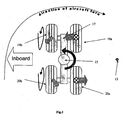
- Each landing year assembly comprises (referring to Figure 3 ) a leg 15, bogie 17 connected in its centre thereto and two pairs of wheels 19, 20 mounted on the bogie.
- Two wheels 19a, 20a are located on a first side of the bogie and two wheels 19b, 20b are located on a second side of the bogie.
- the aircraft 1 also comprises a nose wheel 11 located at the front of the fuselage.
- the aircraft 1 has reached the end of the narrow runway 2 and must therefore perform a tight right-hand turn.
- the engines are on ground idle and are producing only a small amount of forward thrust (shown by the arrows 7' in Figures 1a to 1d ).
- the forward speed of the aircraft is approximately five knots.
- the pilot performs three steps. First the nose wheel 11 is turned to one side. Then the pilot applies the brakes to the wheels of one of the landing gear 9 as indicated by the crossed-circle in Figure 1b and 1c . Finally a thrust is generated suitable for turning the aircraft.
- the forward thrust 7" of the left outermost engine is increased above idle.
- the net effect of the engine thrusts is a net thrust (not shown). The net thrust acts through a centre of thrust (not shown) spaced apart from the centre line of the fuselage, and close to the left-hand outermost engine.
- the aircraft thus turns in a relatively small turning circle about a centre of turning 13 located close to the landing gear 9 on which brakes are applied.
- the landing gear travels, initially in a forward motion, in a tight circle 14 (the movement of the landing gear has been exaggerated for the sake of clarity).
- the pilot reduces the outermost engine thrust to idle, straightens up the nose wheel and releases the brakes on the landing gear 9.
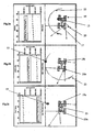
- Figure 2 comprises images from a computer simulation, showing the loads in a landing gear assembly during three different braked pivot turns.
- the graphical displays show the torque in a landing gear leg in a time period of 30 to 80 seconds during the three different braked pivot turns.
- Figure 2a shows a manoeuvre in which all four wheels on the bogie are braked
- Figure 2b shows a manoeuvre in which only the wheels on the side of the bogie further from the centre of turning are braked
- Figure 2c shows a manoeuvre in which only the wheels on the side of the bogie closer to the centre of turning are braked.
- the arrow 23 indicates both the direction and magnitude of forces on the wheels and landing gear leg. The longer the arrow, the greater the magnitude of the force.
- the loads shown on the landing gear assembly are those occurring during a braked pivot manoeuvre in which all four wheels 19, 20 on the bogie 17 are braked.
- the wheels 19, 20 are subjected to considerable frictional loading through scrubbing of the tyres on the runway.
- the frictional force on each wheel is acting in a different direction, but the combined affect of the scrubbing is to generate a primary torque 23 in the landing gear leg.
- the torque is approximately 2.5x10 8 Nmm throughout the time period measured.
- the loads shown on the landing gear are those occurring during a braked pivot manoeuvre in which only the wheels on the side of the bogie 17 that is further from the centre of turning 13 are braked.
- the braked wheels are still subjected to considerable frictional loading due to the tyres 19b, 20b scrubbing on the runway.
- This frictional loading generates a primary torque (not shown) in the landing gear leg 15.
- the net torque 23 in the leg 15 is approximately 3.2x10 8 Nmm throughout the time period measured however. This is significantly higher than that in Figure 2a . It is thought that the increase in torque is due to a secondary torque caused by the differential braking force on the bogie, the secondary torque acting in the same direction as the above-mentioned primary torque.
- Figure 2c shows the loads in a landing gear assembly during a braked pivot manoeuvre in which only the wheels 19a, 20a on the side of the bogie 17 that is closer to the centre of turning 13 are braked (i.e. in accordance with the method of embodiments of the present invention).
- the braked wheels 19a, 20a are subjected to considerable frictional loading due to the tyres scrubbing on the runway 2.
- This frictional loading generates a primary torque in the landing gear.
- the net torque 23 in the leg is approximately 0.5x10 8 Nmm throughout the time period measured however. This is significantly lower than that in Figures 2a (and 2b ). It is thought that the decrease in torque is due to a secondary torque caused by the differential braking force on the bogie, the secondary torque acting in the opposite direction as the primary torque.
- Figure 3 shows a plan view of a bogie 17 on the aircraft 1 performing a braked pivot turn according to a first embodiment of the present invention.
- the aircraft 1 includes a brake control system (not shown) which allows each wheel 19a, 19b, 20a, 20b to be individually braked.
- the aircraft is provided with a brake control system comprising a control unit, a ground speed receiver and a nose wheel angle receiver.
- the brake control system also comprises a brake input receiver which receives a signal when the pilot attempts to apply the brakes to the wheels of the landing gear.
- the control unit is arranged to receive signals relating to the aircraft speed and the nose wheel angle via the ground speed receiver and a nose wheel angle receiver.
- the control unit is also arranged to compare the signal received from the ground speed receiver and the signal received from the nose wheel indicator, to parameter reference thresholds stored in a database within the brake control system.
- the aircraft speed is below the threshold value of 20 knots
- the nose wheel angle is greater than the threshold value of 60 degrees from the centre of the fuselage.
- the brake input receiver receives a signal due to the pilot applying the brake.
- the control unit compares the signals from the receivers to the parameter reference thresholds. In this particular embodiment, the speed and nose wheel angle are outside their respective thresholds.
- the brake control unit therefore effects application of the brakes to only the wheels on the side of the bogie closer to the centre of turning. The torque in the landing gear leg is thereby maintained at an acceptable level such that relatively little fatigue damage occurs.
- Each landing gear need not comprise four wheels.
- the landing gear may comprise two wheels (in which case the term 'bogie' will be understood to mean the structure at one end of the landing gear leg that is common to both wheels, for example the axle).
- the landing gear may comprise 6 or more wheels.
- the steps performed to effect the braked pivot turn need not be made in the order described above. A Jacobs manoeuvre may be effected, rather than the braked pivot turn described in respect of the first embodiment.
Landscapes
- Engineering & Computer Science (AREA)
- Mechanical Engineering (AREA)
- Aviation & Aerospace Engineering (AREA)
- Transportation (AREA)
- Regulating Braking Force (AREA)
- Braking Arrangements (AREA)
- Braking Systems And Boosters (AREA)
- Valves And Accessory Devices For Braking Systems (AREA)
- Retarders (AREA)
Claims (12)
- Procédé de rotation, par pivotement freiné, d'un aéronef (1) au sol, l'aéronef (1) comprenant un fuselage (3) et deux ensembles de train d'atterrissage (9, 10), les ensembles de train d'atterrissage étant situés de chaque côté du fuselage (3) et chaque ensemble de train d'atterrissage comprenant un bogie (17) muni d'une pluralité de roues (19, 20) montées sur lui, au moins une roue (19a, 20a) étant située sur un premier côté du bogie et au moins une roue (19b, 20b) étant située sur un deuxième côté du bogie,
dans lequel le procédé comprend les étapes consistant à :(i) appliquer une poussée appropriée pour déplacer l'aéronef, et(ii) freiner au moins une roue, sur l'ensemble de train d'atterrissage (9) qui est située plus près du centre de giration (13) de l'aéronef, dans lequel, via le freinage d'au moins une roue, une force de freinage plus grande est appliquée au premier côté du bogie (17) qu'au deuxième côté, le premier côté étant situé plus près du centre de giration (13) de l'aéronef que le deuxième côté. - Procédé selon la revendication 1, dans lequel le premier côté est le côté extérieur du bogie (17), et le deuxième côté est le côté intérieur du bogie (17).
- Procédé selon la revendication 1 ou 2, dans lequel la poussée est une poussée différentielle, appropriée pour faire tourner l'aéronef (1).
- Procédé selon l'une quelconque des revendications précédentes, dans lequel au moins une roue de plus est freinée sur le premier côté du bogie (17) que sur le deuxième côté.
- Procédé selon l'une quelconque des revendications précédentes, dans lequel l'aéronef se déplace à une vitesse inférieure à 20 noeuds.
- Procédé selon l'une quelconque des revendications précédentes, l'aéronef (1) comprenant en outre une roue de train d'atterrissage avant (11), dans lequel le procédé comprend en outre l'étape de rotation de la roue de train d'atterrissage avant (11), à un angle supérieur à 45° par rapport à l'axe central du fuselage d'aéronef.
- Procédé selon l'une quelconque des revendications précédentes, comprenant en outre les étapes consistant à :(i) recevoir un premier signal concernant un paramètre d'aéronef, et(ii) appliquer la force de freinage en fonction du signal.
- Procédé selon la revendication 7, comprenant en outre les étapes consistant à :(i) comparer la valeur du paramètre d'aéronef à un seuil de référence de paramètre d'aéronef, et(ii) appliquer la force de freinage, si la valeur du paramètre est hors du seuil de référence.
- Procédé selon l'une quelconque des revendications précédentes, dans lequel le poids à sec de l'aéronef est supérieur à 50 tonnes.
- Aéronef (1), comprenant un fuselage (3) et deux ensemble de train d'atterrissage (9, 10), les ensembles de train d'atterrissage étant situés de chaque côté du fuselage (3) et chaque ensemble de train d'atterrissage comprenant un bogie (17), muni d'une pluralité de roues montées sur lui, au moins une roue (19a, 20a) étant située sur un premier côté du bogie et au moins une roue (19b, 20b) étant située sur un deuxième côté du bogie, l'aéronef comprenant en outre un système de commande de frein, pour freiner sélectivement des roues, situées sur l'ensemble de train d'atterrissage se trouvant plus près du centre de giration (13) de l'aéronef durant une rotation par pivotement freiné caractérisé en ce que le système de commande de frein est agencé pour appliquer, par le biais d'un freinage d'une roue, au premier côté d'un bogie, une force de freinage plus grande qu'au deuxième côté, le premier côté étant situé plus près du centre de giration de l'aéronef que le deuxième côté.
- Aéronef selon la revendication 10. comprenant en outre un récepteur d'entrée de frein, pour recevoir un signal concernant l'application des freins aux roues du train d'atterrissage de l'aéronef, dans lequel le système de commande de frein est agencé pour exercer la force de freinage en fonction du signal reçu par le récepteur d'entrée de frein.
- Aéronef selon la revendication 10 ou 11, comprenant en outre un premier récepteur, pour recevoir un signal concernant un paramètre d'aéronef, et une base de données, pour stocker un seuil de référence de paramètre d'aéronef,
dans lequel le système de commande de frein est agencé pour comparer la valeur du paramètre d'aéronef au seuil de référence de paramètre d'aéronef, et le système de commande de frein est agencé pour effectuer le freinage d'au moins une roue, en fonction de la comparaison du paramètre d'aéronef au seuil de référence de paramètre d'aéronef.
Applications Claiming Priority (2)
| Application Number | Priority Date | Filing Date | Title |
|---|---|---|---|
| GBGB0523069.3A GB0523069D0 (en) | 2005-11-11 | 2005-11-11 | Aircraft braking system |
| PCT/GB2006/004206 WO2007054715A1 (fr) | 2005-11-11 | 2006-11-10 | Systeme de freinage d'avion |
Publications (2)
| Publication Number | Publication Date |
|---|---|
| EP1948505A1 EP1948505A1 (fr) | 2008-07-30 |
| EP1948505B1 true EP1948505B1 (fr) | 2009-09-02 |
Family
ID=35516803
Family Applications (1)
| Application Number | Title | Priority Date | Filing Date |
|---|---|---|---|
| EP06808499A Active EP1948505B1 (fr) | 2005-11-11 | 2006-11-10 | Systeme de freinage d'avion |
Country Status (11)
| Country | Link |
|---|---|
| US (1) | US8376273B2 (fr) |
| EP (1) | EP1948505B1 (fr) |
| JP (1) | JP5126610B2 (fr) |
| CN (1) | CN101304919B (fr) |
| AT (1) | ATE441574T1 (fr) |
| BR (1) | BRPI0618518A2 (fr) |
| CA (1) | CA2629140C (fr) |
| DE (1) | DE602006008975D1 (fr) |
| GB (1) | GB0523069D0 (fr) |
| RU (1) | RU2416549C2 (fr) |
| WO (1) | WO2007054715A1 (fr) |
Families Citing this family (14)
| Publication number | Priority date | Publication date | Assignee | Title |
|---|---|---|---|---|
| FR2918639B1 (fr) * | 2007-07-09 | 2010-01-08 | Airbus France | Systeme de freinage differentiel. |
| DE102008011791B4 (de) * | 2008-02-29 | 2013-09-19 | Airbus Operations Gmbh | Integriertes multifunktionales Radantriebssystem für Luftfahrzeuge |
| FR2965074B1 (fr) * | 2010-09-21 | 2012-08-31 | Messier Bugatti | Procede de gestion d'un mouvement au sol d'un aeronef. |
| FR2982822B1 (fr) * | 2011-11-22 | 2014-08-01 | Messier Bugatti Dowty | Procede de gestion du freinage d'un aeronef permettant de limiter son tangage |
| GB201220616D0 (en) * | 2012-11-16 | 2013-01-02 | Airbus Operations Ltd | Aircraft landing gear longitudinal force control |
| GB2528317A (en) * | 2014-07-18 | 2016-01-20 | Airbus Operations Sas | Differential braking of aircraft landing gear wheels |
| GB2533179B (en) * | 2014-12-10 | 2020-08-26 | Airbus Operations Ltd | Control method and apparatus for an aircraft when taxiing |
| CN104773306B (zh) * | 2015-04-07 | 2017-02-01 | 中国直升机设计研究所 | 一种主起落架三向加载试验装置 |
| CN105083542B (zh) * | 2015-07-20 | 2017-04-12 | 西安航空制动科技有限公司 | 一种采用差动刹车控制飞机最小半径极限转弯的方法 |
| FR3089494B1 (fr) * | 2018-12-05 | 2022-04-08 | Safran Landing Systems | Procédé d’asservissement en vitesse d’un dispositif d’entraînement en rotation des roues d’un aéronef |
| GB2583706A (en) * | 2019-04-23 | 2020-11-11 | Airbus Operations Ltd | Aircraft braking system |
| US11390380B2 (en) * | 2019-10-10 | 2022-07-19 | The Boeing Company | System and method for alleviating structural loads on a pivoting main landing gear of an aircraft in a pivot turn maneuver |
| GB2603773A (en) * | 2021-02-11 | 2022-08-17 | Airbus Operations Ltd | An aircraft brake control system |
| CN114313234B (zh) * | 2022-02-10 | 2024-05-07 | 中国商用飞机有限责任公司 | 多轮起落架转向系统及其控制方法 |
Family Cites Families (131)
| Publication number | Priority date | Publication date | Assignee | Title |
|---|---|---|---|---|
| US1573100A (en) * | 1922-06-08 | 1926-02-16 | America The Bank Of | Means for guiding aeroplanes on the ground |
| US1622145A (en) | 1923-12-12 | 1927-03-22 | Gen Motors Res Corp | Generator-regulating apparatus |
| US1931282A (en) | 1932-03-12 | 1933-10-17 | Boykow Johann Maria | Automatic steering device |
| US2128044A (en) | 1935-10-26 | 1938-08-23 | Westinghouse Electric & Mfg Co | Dynamo-electric machine |
| US2149634A (en) | 1936-09-10 | 1939-03-07 | Jr Edmund O Schweitzer | Transformer fault indicating means |
| GB481946A (en) * | 1936-09-21 | 1938-03-21 | Bendix Ltd | Improvements in or relating to the control of aircraft brakes |
| US2355026A (en) | 1943-10-09 | 1944-08-01 | Gen Aircraft Corp | Airplane |
| US2475461A (en) | 1945-02-12 | 1949-07-05 | Lear Inc | Electric remote-control system |
| US2564320A (en) | 1948-12-17 | 1951-08-14 | Keefe And Merritt Company O | Permanent magnet type electric generator |
| GB711832A (en) | 1949-02-11 | 1954-07-14 | Electro Hydraulics Ltd | Improvements in steering means for aircraft landing gear |
| US2767368A (en) | 1950-12-21 | 1956-10-16 | Kober William | Dynamoelectric control |
| US2794609A (en) * | 1953-11-30 | 1957-06-04 | Lockheed Aircraft Corp | Multiple brake system for aircraft |
| US2911168A (en) * | 1955-10-25 | 1959-11-03 | William J Moreland | Differentially controlled twin wheel landing gear |
| US2914359A (en) | 1955-12-01 | 1959-11-24 | Gordon W Yarber | Anti-skid brake control system |
| US2891742A (en) | 1956-05-29 | 1959-06-23 | Sperry Rand Corp | Flight control system for aircraft |
| US3017145A (en) | 1958-09-04 | 1962-01-16 | Gordon W Yarber | Control system for vehicle wheel brake |
| US2998538A (en) | 1959-03-06 | 1961-08-29 | Sarl Auxilec | Continuously variable speed drive system |
| GB902155A (en) | 1961-01-19 | 1962-07-25 | Brevets Aero Mecaniques | Improvements in and relating to electro-magnetic brakes |
| US3292021A (en) | 1963-04-22 | 1966-12-13 | Avco Corp | Superconductive device |
| US3310976A (en) | 1963-10-17 | 1967-03-28 | Bussell Bertram | Aircraft weight and center of gravity apparatus |
| US3344325A (en) | 1965-05-04 | 1967-09-26 | Honeywell Inc | Step motor including permanent magnet rotor and sectioned stator |
| US3396325A (en) | 1965-07-21 | 1968-08-06 | Ralph E. Hopkins | Voltage control of permanent magnet generators |
| DE1273334B (de) | 1967-01-05 | 1968-07-18 | Licentia Gmbh | Antrieb fuer ein Flugzeug-Fahrwerksrad |
| DE1273335B (de) | 1967-01-05 | 1968-07-18 | Lloyd Dynamowerke G M B H | Antrieb fuer ein Flugzeug-Fahrwerksrad |
| US3622977A (en) | 1968-03-30 | 1971-11-23 | Hisato Wakamatsu | Slip warning system for automotive vehicles |
| US3466518A (en) | 1968-04-24 | 1969-09-09 | Ncr Co | Rotary stepping motors and control systems therefor |
| US3671788A (en) | 1970-11-30 | 1972-06-20 | Gen Lab Associates Inc | Regulatable alternator |
| FR2274158A1 (fr) | 1974-06-07 | 1976-01-02 | Anvar | Perfectionnements aux machines electriques tournantes a bobinage supraconducteur |
| US4008868A (en) * | 1975-12-18 | 1977-02-22 | The United States Of America As Represented By The Secretary Of The Navy | Aircraft steering and braking system |
| US4223255A (en) | 1977-10-28 | 1980-09-16 | Goldman Gary S | Electric wheel |
| FR2478020A1 (fr) * | 1980-03-11 | 1981-09-18 | Aerospatiale | Procede et dispositif pour le freinage d'aeronefs a large voie roulant sur le sol |
| US4488053A (en) | 1981-02-17 | 1984-12-11 | Lockheed Corporation | Electric constant speed/variable speed drive/generator assembly |
| JPS57146164A (en) | 1981-03-05 | 1982-09-09 | Secoh Giken Inc | Speed detecting device for disk type motor |
| US4585085A (en) | 1981-08-20 | 1986-04-29 | Handel Peter H | Electric wheel-drive for motor vehicles, in particular for nondestructive hybridization of automobiles |
| US4482961A (en) * | 1981-09-18 | 1984-11-13 | The Boeing Company | Automatic control system for directional control of an aircraft during landing rollout |
| FR2522602A1 (fr) | 1982-03-05 | 1983-09-09 | Messier Hispano Sa | Dispositif pour la commande d'un systeme de freinage de vehicule notamment d'un aeronef |
| US4567391A (en) | 1982-08-20 | 1986-01-28 | Octa, Inc. | Permanent magnet disc rotor machine |
| JPS59181956A (ja) | 1983-03-31 | 1984-10-16 | Oopack Kk | 無刷子直流回転電機 |
| US4659040A (en) | 1983-05-12 | 1987-04-21 | Sinclair Graham R | Aircraft undercarriage assemblies |
| US4562399A (en) | 1983-06-14 | 1985-12-31 | Kollmorgen Technologies Corporation | Brushless DC tachometer |
| US4642539A (en) | 1985-06-10 | 1987-02-10 | Northern Magnetics, Inc. | Torque motor with unlimited angular excursion |
| US4687158A (en) | 1985-07-15 | 1987-08-18 | Lockheed Corporation | Jump strut landing gear apparatus and system |
| JPS62265023A (ja) | 1986-05-12 | 1987-11-17 | Isuzu Motors Ltd | 車輪駆動装置 |
| US6398162B1 (en) | 1988-02-16 | 2002-06-04 | Dunlop Limited | Aircraft braking systems |
| US4885526A (en) | 1988-03-18 | 1989-12-05 | Electro Erg Limited | Compensation circuit for electrical generators |
| US4923056A (en) * | 1989-02-21 | 1990-05-08 | Aircraft Braking Systems Corporation | Method of increasing the service life of aircraft carbon disk brakes |
| US5182958A (en) | 1989-11-04 | 1993-02-02 | Black James W | Non-linear propulsion and energy conversion system |
| US6604708B1 (en) * | 1989-12-26 | 2003-08-12 | The Boeing Company | Carbon brake wear for aircraft |
| JPH03295796A (ja) | 1990-04-16 | 1991-12-26 | Mitsubishi Heavy Ind Ltd | 飛行機用着陸装置 |
| US5097140A (en) | 1991-05-07 | 1992-03-17 | Chrysler Corporation | Alternator starter |
| US5175462A (en) | 1991-08-30 | 1992-12-29 | Fuji Xerox Co., Ltd. | Toroidal coil motor |
| US5207304A (en) | 1991-12-03 | 1993-05-04 | The Regents Of The University Of California | Inductive energization system and method for vehicles |
| RU2023630C1 (ru) | 1992-06-30 | 1994-11-30 | Белла Николаевна Комарова | Система автоматического управления курсовым положением самолета |
| FR2701435B1 (fr) | 1993-02-15 | 1995-03-31 | Smh Management Services Ag | Véhicule automobile à traction électrique comprenant un dispositif de récupération d'énergie. |
| EP0686106B1 (fr) * | 1993-03-06 | 1998-11-18 | Dunlop Limited | Fonctionnement selectif sequentiel de freins d'avions |
| AU687847B2 (en) | 1993-06-14 | 1998-03-05 | Ecoair Corp. | Hybrid alternator with voltage regulator |
| US5397975A (en) | 1993-06-14 | 1995-03-14 | Ecoair Corp. | Hybrid alternator |
| US5998307A (en) | 1993-08-04 | 1999-12-07 | Borg-Warner Autotive, Inc. | Fibrous lining material comprising a primary layer having less fibrillated aramid fibers and synthetic graphite and a secondary layer comprising carbon particles |
| GB9320661D0 (en) | 1993-10-07 | 1993-11-24 | Lucas Ind Public Limited | Electric vehicle having abs |
| US5704568A (en) * | 1994-03-09 | 1998-01-06 | The Boeing Company | Airplane pirouette steering system |
| US5669470A (en) | 1994-05-05 | 1997-09-23 | H. R. Ross Industries, Inc. | Roadway-powered electric vehicle system |
| JP3515628B2 (ja) | 1995-04-14 | 2004-04-05 | 株式会社明電舎 | 電気自動車の駆動機構 |
| JP3687804B2 (ja) | 1995-12-22 | 2005-08-24 | 日立金属株式会社 | 回転機用磁石回転子 |
| JPH09275673A (ja) | 1996-03-28 | 1997-10-21 | Tai-Haa Yan | 共通構造を有する三層電気機械構造を備えた組合せ 電力駆動装置 |
| US6149100A (en) * | 1996-04-10 | 2000-11-21 | The Boeing Company | Aircraft landing gear having axle to brake plate integration |
| US5721473A (en) | 1996-04-18 | 1998-02-24 | Devries; Leroy Milo | Electric motorized vehicular wheel with adjuncts |
| GB9612231D0 (en) | 1996-06-12 | 1996-08-14 | Harris Michael A | Variable transmission apparatus |
| US5944147A (en) | 1996-06-28 | 1999-08-31 | Alliedsignal Inc. | Integrated aircraft wheel, brake and axle |
| US6411002B1 (en) | 1996-12-11 | 2002-06-25 | Smith Technology Development | Axial field electric machine |
| US6132016A (en) | 1997-05-02 | 2000-10-17 | Hydro-Aire, Inc. | System and method for adaptive brake application and initial skid detection |
| US6220676B1 (en) | 1997-05-09 | 2001-04-24 | The B. F. Goodrich Company | Antiskid control of multi-wheel vehicles using coupled and decoupled Kalman filtering incorporating pitch weight transfer |
| JP3767103B2 (ja) | 1997-07-16 | 2006-04-19 | 日産自動車株式会社 | 電気自動車の制御装置 |
| JP3096447B2 (ja) | 1997-09-17 | 2000-10-10 | 本田技研工業株式会社 | ハイブリッド車両の制御装置 |
| EP1019883B1 (fr) | 1997-10-06 | 2002-02-27 | Siemens Aktiengesellschaft | Procede et dispositif de guidage a assistance automatique d'aeronefs vers un emplacement de stationnement |
| US6064135A (en) | 1998-04-07 | 2000-05-16 | David H. Rush | Electromechanical machine and armature structure therefor |
| US6118202A (en) | 1998-05-11 | 2000-09-12 | Active Power, Inc. | High-efficiency inductor-alternator |
| JP3410022B2 (ja) | 1998-05-20 | 2003-05-26 | 本田技研工業株式会社 | ハイブリッド車両の制御装置 |
| EP1759915A3 (fr) | 1998-07-21 | 2007-03-14 | TOKYO R&D CO., LTD. | Véhicule hybride et procédé de gestion du déplacement du véhicule |
| GB9817757D0 (en) | 1998-08-15 | 1998-10-14 | Dunlop Ltd | Breaking system |
| JP3622529B2 (ja) | 1998-09-11 | 2005-02-23 | トヨタ自動車株式会社 | 動力出力装置、およびそれを搭載したハイブリッド車両並びに原動機の動作点制御方法 |
| JP3525218B2 (ja) | 1998-09-18 | 2004-05-10 | 本田技研工業株式会社 | ハイブリッド車両の回生制御装置 |
| US6766874B2 (en) | 1998-09-29 | 2004-07-27 | Hitachi, Ltd. | System for driving hybrid vehicle, method thereof and electric power supply system therefor |
| EP1147593A4 (fr) | 1998-12-22 | 2005-08-17 | Rush Holdings Inc | Machine a armature et a entrefer en forme de coupelle |
| US6046518A (en) | 1999-01-21 | 2000-04-04 | Williams; Malcolm R. | Axial gap electrical machine |
| US6513885B1 (en) * | 1999-05-14 | 2003-02-04 | Hydro-Aire, Inc. | Dual redundant active/active brake-by-wire architecture |
| US6402259B2 (en) | 1999-07-14 | 2002-06-11 | Goodrich Corporation | Electromechanical braking system with power distribution and redundancy |
| US6885920B2 (en) | 1999-07-30 | 2005-04-26 | Oshkosh Truck Corporation | Control system and method for electric vehicle |
| US6633106B1 (en) | 1999-09-30 | 2003-10-14 | Dwight W. Swett | Axial gap motor-generator for high speed operation |
| DE60027840T2 (de) | 1999-11-18 | 2006-12-28 | Denso Corp., Kariya | Rotierende elektrische Maschine für Fahrzeuge |
| JP2001238303A (ja) | 2000-02-24 | 2001-08-31 | Mitsubishi Motors Corp | ハイブリッド電気自動車の回生制御装置 |
| US6493618B2 (en) | 2000-03-15 | 2002-12-10 | Toyota Jidosha Kabushiki Kaisha | Vehicle control using multiple sensors |
| JP3366899B2 (ja) | 2000-06-13 | 2003-01-14 | 東海旅客鉄道株式会社 | 回生ブレーキ |
| RU2213408C2 (ru) | 2000-06-26 | 2003-09-27 | Общество с ограниченной ответственностью Научно-Производственное Предприятие "ТЕХНОКРАТ" | Торцевой наборный электромотор |
| US6573675B2 (en) | 2000-12-27 | 2003-06-03 | Transportation Techniques Llc | Method and apparatus for adaptive energy control of hybrid electric vehicle propulsion |
| JP3638586B2 (ja) | 2001-04-16 | 2005-04-13 | 株式会社ブリヂストン | インホイールモータの取付方法及びインホイールモータシステム |
| US6659400B2 (en) | 2001-05-23 | 2003-12-09 | Hydro-Aire, Inc. | Optimal control design for aircraft antiskid brake control systems |
| US6910844B2 (en) | 2001-07-01 | 2005-06-28 | William B. Trescott | Self-loading vehicle for shipping containers |
| US6450448B1 (en) | 2001-08-17 | 2002-09-17 | Toshimi Suzuki | Airplane wheel unit |
| US6484072B1 (en) | 2001-09-28 | 2002-11-19 | The United States Of America As Represented By The Secretary Of The Navy | Embedded terrain awareness warning system for aircraft |
| JP3712652B2 (ja) | 2001-09-28 | 2005-11-02 | ジヤトコ株式会社 | パラレルハイブリッド車両 |
| CN1285154C (zh) | 2001-11-29 | 2006-11-15 | 雅马哈发动机株式会社 | 轴隙式旋转电机 |
| US6768932B2 (en) | 2001-12-07 | 2004-07-27 | General Motors Corporation | Wheel motor system |
| JP2003189409A (ja) | 2001-12-21 | 2003-07-04 | Toyota Motor Corp | 電動機搭載車両 |
| JP3616847B2 (ja) | 2001-12-25 | 2005-02-02 | 川崎重工業株式会社 | 陸上移動体の回生制動装置 |
| US6671588B2 (en) | 2001-12-27 | 2003-12-30 | Toyota Jidosha Kabushiki Kaisha | System and method for controlling traveling direction of aircraft |
| US7248006B2 (en) | 2002-07-01 | 2007-07-24 | Xidem, Inc. | Electronically controlled electric motor |
| US20040263099A1 (en) | 2002-07-31 | 2004-12-30 | Maslov Boris A | Electric propulsion system |
| US20040040756A1 (en) | 2002-09-03 | 2004-03-04 | Abdulareef Nmngani | Gyroscopically stabilized vehicle |
| JP4151384B2 (ja) | 2002-11-07 | 2008-09-17 | 日産自動車株式会社 | 燃料電池システム |
| FR2850926B1 (fr) | 2003-02-07 | 2007-03-16 | Messier Bugatti | Frein electromecanique a dispositif de parc |
| US20040155468A1 (en) | 2003-02-12 | 2004-08-12 | Tai-Her Yang | Series and parallel combined dual power drive system |
| JP2004248432A (ja) | 2003-02-14 | 2004-09-02 | Toyota Motor Corp | 駆動装置およびこれを備える自動車 |
| US7411371B2 (en) | 2003-02-28 | 2008-08-12 | Arizona Public Service Company | Battery charger and method of charging a battery |
| US6758440B1 (en) | 2003-03-21 | 2004-07-06 | Curtiss-Wright Electro-Mechanical Corporation | Electromagnetic aircraft arrestor system |
| US20040212259A1 (en) | 2003-04-24 | 2004-10-28 | Gould Len Charles | Wheel motor |
| US7262536B2 (en) | 2003-08-11 | 2007-08-28 | General Motors Corporation | Gearless wheel motor drive system |
| US6851649B1 (en) * | 2003-08-14 | 2005-02-08 | The Boeing Company | Methods and systems for controlling wheel brakes on aircraft and other vehicles |
| JP4111903B2 (ja) | 2003-10-20 | 2008-07-02 | 東海旅客鉄道株式会社 | 飛翔体発射装置および飛翔体発射方法 |
| US7510058B2 (en) | 2003-11-25 | 2009-03-31 | Honeywell International Inc. | Electric park brake mechanism and method of operating an electric brake to perform a park brake function |
| US7237748B2 (en) | 2003-12-15 | 2007-07-03 | Delos Aerospace, Llc | Landing gear method and apparatus for braking and maneuvering |
| WO2005079461A2 (fr) | 2004-02-17 | 2005-09-01 | Pneuvolt, Inc. | Systeme de vehicule pour recapturer l'energie cinetique |
| JP2005253126A (ja) | 2004-03-01 | 2005-09-15 | Nissan Motor Co Ltd | ハイブリッド車両の制動力制御装置および該制御装置を搭載した車両 |
| FR2869015B1 (fr) | 2004-04-16 | 2006-06-30 | Airbus France Sas | Procede et dispositif pour la conduite et le freinage d'un aeronef roulant sur le sol. |
| JP3968785B2 (ja) | 2004-05-18 | 2007-08-29 | セイコーエプソン株式会社 | 駆動回生制御システム |
| US7281684B2 (en) * | 2005-02-23 | 2007-10-16 | The Boeing Company | Systems and methods for braking aircraft, including braking intermediate main gears and differential braking |
| FR2887222B1 (fr) * | 2005-06-15 | 2007-08-10 | Airbus France Sas | Procede et dispositif pour la conduite d'un aeronef roulant sur le sol |
| US7975960B2 (en) * | 2005-08-29 | 2011-07-12 | Borealis Technical Limited | Nosewheel control apparatus |
| US7410224B2 (en) * | 2006-01-19 | 2008-08-12 | Hydro-Aire, Inc. | Method and system to increase electric brake clamping force accuracy |
| US8016366B2 (en) * | 2006-06-02 | 2011-09-13 | Goodrich Corporation | Differential brake control and weighted average wheel speed for brake control system |
| FR2918639B1 (fr) * | 2007-07-09 | 2010-01-08 | Airbus France | Systeme de freinage differentiel. |
| US9216720B2 (en) * | 2009-04-30 | 2015-12-22 | Goodrich Corporation | Differential emergency/park electric brake system |
-
2005
- 2005-11-11 GB GBGB0523069.3A patent/GB0523069D0/en not_active Ceased
-
2006
- 2006-11-10 EP EP06808499A patent/EP1948505B1/fr active Active
- 2006-11-10 JP JP2008539500A patent/JP5126610B2/ja not_active Expired - Fee Related
- 2006-11-10 RU RU2008123217/11A patent/RU2416549C2/ru not_active IP Right Cessation
- 2006-11-10 DE DE602006008975T patent/DE602006008975D1/de active Active
- 2006-11-10 AT AT06808499T patent/ATE441574T1/de not_active IP Right Cessation
- 2006-11-10 US US12/091,494 patent/US8376273B2/en not_active Expired - Fee Related
- 2006-11-10 WO PCT/GB2006/004206 patent/WO2007054715A1/fr not_active Ceased
- 2006-11-10 BR BRPI0618518-5A patent/BRPI0618518A2/pt not_active IP Right Cessation
- 2006-11-10 CA CA2629140A patent/CA2629140C/fr not_active Expired - Fee Related
- 2006-11-10 CN CN2006800421273A patent/CN101304919B/zh not_active Expired - Fee Related
Also Published As
| Publication number | Publication date |
|---|---|
| US8376273B2 (en) | 2013-02-19 |
| JP5126610B2 (ja) | 2013-01-23 |
| RU2008123217A (ru) | 2009-12-20 |
| CN101304919A (zh) | 2008-11-12 |
| CA2629140C (fr) | 2015-01-27 |
| EP1948505A1 (fr) | 2008-07-30 |
| DE602006008975D1 (de) | 2009-10-15 |
| JP2009515751A (ja) | 2009-04-16 |
| ATE441574T1 (de) | 2009-09-15 |
| CA2629140A1 (fr) | 2007-05-18 |
| CN101304919B (zh) | 2010-05-19 |
| BRPI0618518A2 (pt) | 2011-09-06 |
| WO2007054715A1 (fr) | 2007-05-18 |
| RU2416549C2 (ru) | 2011-04-20 |
| GB0523069D0 (en) | 2005-12-21 |
| US20080283660A1 (en) | 2008-11-20 |
Similar Documents
| Publication | Publication Date | Title |
|---|---|---|
| EP1948505B1 (fr) | Systeme de freinage d'avion | |
| CN102869573B (zh) | 飞机牵引车及使用该飞机牵引车抓取和拉拽飞机的方法 | |
| US7300020B2 (en) | Systems and methods for braking aircraft, including braking intermediate main gears and differential braking | |
| CN111483588B (zh) | 飞行器起落架轮的差动制动 | |
| CN111114761B (zh) | 飞行器起落架纵向力控制 | |
| WO2009135472A2 (fr) | Dispositif au sol destiné aux processus de décollage, d'atterrissage et de roulage d'avions | |
| CN103419941B (zh) | 侧向控制改进法和设备、侧控和电动飞行控制系统及飞机 | |
| US4638962A (en) | Jumbo aircraft, in particular of high-wing monoplane design | |
| US20170355452A1 (en) | Aircraft landing gear, aircraft carrying such and methods | |
| US7963481B2 (en) | Method and device for supporting the take-off rotation of an aircraft | |
| EP2516267B1 (fr) | Dispositif de commande pour avions | |
| JP2009515751A5 (fr) | ||
| US8340838B2 (en) | Differential braking system | |
| US11535365B2 (en) | Aircraft landing with elevator down force assistance during braking | |
| US12172619B2 (en) | Brake control system | |
| US2696957A (en) | Landing and launching system for aircraft | |
| RU2733666C1 (ru) | Способ автоматического формирования вспомогательных сигналов на наземном участке движения самолета | |
| Jenkins et al. | Tricycle Landing Gear Design-Part 1 |
Legal Events
| Date | Code | Title | Description |
|---|---|---|---|
| PUAI | Public reference made under article 153(3) epc to a published international application that has entered the european phase |
Free format text: ORIGINAL CODE: 0009012 |
|
| 17P | Request for examination filed |
Effective date: 20080611 |
|
| AK | Designated contracting states |
Kind code of ref document: A1 Designated state(s): AT BE BG CH CY CZ DE DK EE ES FI FR GB GR HU IE IS IT LI LT LU LV MC NL PL PT RO SE SI SK TR |
|
| 17Q | First examination report despatched |
Effective date: 20080911 |
|
| GRAP | Despatch of communication of intention to grant a patent |
Free format text: ORIGINAL CODE: EPIDOSNIGR1 |
|
| GRAS | Grant fee paid |
Free format text: ORIGINAL CODE: EPIDOSNIGR3 |
|
| GRAA | (expected) grant |
Free format text: ORIGINAL CODE: 0009210 |
|
| AK | Designated contracting states |
Kind code of ref document: B1 Designated state(s): AT BE BG CH CY CZ DE DK EE ES FI FR GB GR HU IE IS IT LI LT LU LV MC NL PL PT RO SE SI SK TR |
|
| REG | Reference to a national code |
Ref country code: CH Ref legal event code: EP |
|
| REG | Reference to a national code |
Ref country code: IE Ref legal event code: FG4D |
|
| REF | Corresponds to: |
Ref document number: 602006008975 Country of ref document: DE Date of ref document: 20091015 Kind code of ref document: P |
|
| PG25 | Lapsed in a contracting state [announced via postgrant information from national office to epo] |
Ref country code: SE Free format text: LAPSE BECAUSE OF FAILURE TO SUBMIT A TRANSLATION OF THE DESCRIPTION OR TO PAY THE FEE WITHIN THE PRESCRIBED TIME-LIMIT Effective date: 20090902 Ref country code: LT Free format text: LAPSE BECAUSE OF FAILURE TO SUBMIT A TRANSLATION OF THE DESCRIPTION OR TO PAY THE FEE WITHIN THE PRESCRIBED TIME-LIMIT Effective date: 20090902 Ref country code: FI Free format text: LAPSE BECAUSE OF FAILURE TO SUBMIT A TRANSLATION OF THE DESCRIPTION OR TO PAY THE FEE WITHIN THE PRESCRIBED TIME-LIMIT Effective date: 20090902 |
|
| NLV1 | Nl: lapsed or annulled due to failure to fulfill the requirements of art. 29p and 29m of the patents act | ||
| LTIE | Lt: invalidation of european patent or patent extension |
Effective date: 20090902 |
|
| PG25 | Lapsed in a contracting state [announced via postgrant information from national office to epo] |
Ref country code: LV Free format text: LAPSE BECAUSE OF FAILURE TO SUBMIT A TRANSLATION OF THE DESCRIPTION OR TO PAY THE FEE WITHIN THE PRESCRIBED TIME-LIMIT Effective date: 20090902 Ref country code: NL Free format text: LAPSE BECAUSE OF FAILURE TO SUBMIT A TRANSLATION OF THE DESCRIPTION OR TO PAY THE FEE WITHIN THE PRESCRIBED TIME-LIMIT Effective date: 20090902 Ref country code: PL Free format text: LAPSE BECAUSE OF FAILURE TO SUBMIT A TRANSLATION OF THE DESCRIPTION OR TO PAY THE FEE WITHIN THE PRESCRIBED TIME-LIMIT Effective date: 20090902 Ref country code: SI Free format text: LAPSE BECAUSE OF FAILURE TO SUBMIT A TRANSLATION OF THE DESCRIPTION OR TO PAY THE FEE WITHIN THE PRESCRIBED TIME-LIMIT Effective date: 20090902 |
|
| PG25 | Lapsed in a contracting state [announced via postgrant information from national office to epo] |
Ref country code: CY Free format text: LAPSE BECAUSE OF FAILURE TO SUBMIT A TRANSLATION OF THE DESCRIPTION OR TO PAY THE FEE WITHIN THE PRESCRIBED TIME-LIMIT Effective date: 20090902 |
|
| PG25 | Lapsed in a contracting state [announced via postgrant information from national office to epo] |
Ref country code: PT Free format text: LAPSE BECAUSE OF FAILURE TO SUBMIT A TRANSLATION OF THE DESCRIPTION OR TO PAY THE FEE WITHIN THE PRESCRIBED TIME-LIMIT Effective date: 20100104 Ref country code: CZ Free format text: LAPSE BECAUSE OF FAILURE TO SUBMIT A TRANSLATION OF THE DESCRIPTION OR TO PAY THE FEE WITHIN THE PRESCRIBED TIME-LIMIT Effective date: 20090902 Ref country code: IS Free format text: LAPSE BECAUSE OF FAILURE TO SUBMIT A TRANSLATION OF THE DESCRIPTION OR TO PAY THE FEE WITHIN THE PRESCRIBED TIME-LIMIT Effective date: 20100102 Ref country code: ES Free format text: LAPSE BECAUSE OF FAILURE TO SUBMIT A TRANSLATION OF THE DESCRIPTION OR TO PAY THE FEE WITHIN THE PRESCRIBED TIME-LIMIT Effective date: 20091213 Ref country code: EE Free format text: LAPSE BECAUSE OF FAILURE TO SUBMIT A TRANSLATION OF THE DESCRIPTION OR TO PAY THE FEE WITHIN THE PRESCRIBED TIME-LIMIT Effective date: 20090902 Ref country code: RO Free format text: LAPSE BECAUSE OF FAILURE TO SUBMIT A TRANSLATION OF THE DESCRIPTION OR TO PAY THE FEE WITHIN THE PRESCRIBED TIME-LIMIT Effective date: 20090902 |
|
| PG25 | Lapsed in a contracting state [announced via postgrant information from national office to epo] |
Ref country code: SK Free format text: LAPSE BECAUSE OF FAILURE TO SUBMIT A TRANSLATION OF THE DESCRIPTION OR TO PAY THE FEE WITHIN THE PRESCRIBED TIME-LIMIT Effective date: 20090902 |
|
| PG25 | Lapsed in a contracting state [announced via postgrant information from national office to epo] |
Ref country code: AT Free format text: LAPSE BECAUSE OF FAILURE TO SUBMIT A TRANSLATION OF THE DESCRIPTION OR TO PAY THE FEE WITHIN THE PRESCRIBED TIME-LIMIT Effective date: 20090902 Ref country code: BE Free format text: LAPSE BECAUSE OF FAILURE TO SUBMIT A TRANSLATION OF THE DESCRIPTION OR TO PAY THE FEE WITHIN THE PRESCRIBED TIME-LIMIT Effective date: 20090902 Ref country code: MC Free format text: LAPSE BECAUSE OF NON-PAYMENT OF DUE FEES Effective date: 20091130 |
|
| RAP2 | Party data changed (patent owner data changed or rights of a patent transferred) |
Owner name: AIRBUS OPERATIONS LIMITED |
|
| PLBE | No opposition filed within time limit |
Free format text: ORIGINAL CODE: 0009261 |
|
| STAA | Information on the status of an ep patent application or granted ep patent |
Free format text: STATUS: NO OPPOSITION FILED WITHIN TIME LIMIT |
|
| PG25 | Lapsed in a contracting state [announced via postgrant information from national office to epo] |
Ref country code: DK Free format text: LAPSE BECAUSE OF FAILURE TO SUBMIT A TRANSLATION OF THE DESCRIPTION OR TO PAY THE FEE WITHIN THE PRESCRIBED TIME-LIMIT Effective date: 20090902 |
|
| 26N | No opposition filed |
Effective date: 20100603 |
|
| PG25 | Lapsed in a contracting state [announced via postgrant information from national office to epo] |
Ref country code: IE Free format text: LAPSE BECAUSE OF NON-PAYMENT OF DUE FEES Effective date: 20091110 Ref country code: GR Free format text: LAPSE BECAUSE OF FAILURE TO SUBMIT A TRANSLATION OF THE DESCRIPTION OR TO PAY THE FEE WITHIN THE PRESCRIBED TIME-LIMIT Effective date: 20091203 |
|
| PG25 | Lapsed in a contracting state [announced via postgrant information from national office to epo] |
Ref country code: BG Free format text: LAPSE BECAUSE OF FAILURE TO SUBMIT A TRANSLATION OF THE DESCRIPTION OR TO PAY THE FEE WITHIN THE PRESCRIBED TIME-LIMIT Effective date: 20091130 |
|
| PG25 | Lapsed in a contracting state [announced via postgrant information from national office to epo] |
Ref country code: LU Free format text: LAPSE BECAUSE OF NON-PAYMENT OF DUE FEES Effective date: 20091110 |
|
| PG25 | Lapsed in a contracting state [announced via postgrant information from national office to epo] |
Ref country code: HU Free format text: LAPSE BECAUSE OF FAILURE TO SUBMIT A TRANSLATION OF THE DESCRIPTION OR TO PAY THE FEE WITHIN THE PRESCRIBED TIME-LIMIT Effective date: 20100303 |
|
| REG | Reference to a national code |
Ref country code: CH Ref legal event code: PL |
|
| PG25 | Lapsed in a contracting state [announced via postgrant information from national office to epo] |
Ref country code: LI Free format text: LAPSE BECAUSE OF NON-PAYMENT OF DUE FEES Effective date: 20101130 Ref country code: CH Free format text: LAPSE BECAUSE OF NON-PAYMENT OF DUE FEES Effective date: 20101130 |
|
| PG25 | Lapsed in a contracting state [announced via postgrant information from national office to epo] |
Ref country code: TR Free format text: LAPSE BECAUSE OF FAILURE TO SUBMIT A TRANSLATION OF THE DESCRIPTION OR TO PAY THE FEE WITHIN THE PRESCRIBED TIME-LIMIT Effective date: 20090902 |
|
| PGFP | Annual fee paid to national office [announced via postgrant information from national office to epo] |
Ref country code: IT Payment date: 20091130 Year of fee payment: 4 |
|
| REG | Reference to a national code |
Ref country code: FR Ref legal event code: PLFP Year of fee payment: 10 |
|
| REG | Reference to a national code |
Ref country code: FR Ref legal event code: PLFP Year of fee payment: 11 |
|
| REG | Reference to a national code |
Ref country code: FR Ref legal event code: PLFP Year of fee payment: 12 |
|
| PGFP | Annual fee paid to national office [announced via postgrant information from national office to epo] |
Ref country code: DE Payment date: 20191121 Year of fee payment: 14 |
|
| PGFP | Annual fee paid to national office [announced via postgrant information from national office to epo] |
Ref country code: FR Payment date: 20191120 Year of fee payment: 14 |
|
| PGFP | Annual fee paid to national office [announced via postgrant information from national office to epo] |
Ref country code: GB Payment date: 20191120 Year of fee payment: 14 |
|
| REG | Reference to a national code |
Ref country code: DE Ref legal event code: R119 Ref document number: 602006008975 Country of ref document: DE |
|
| GBPC | Gb: european patent ceased through non-payment of renewal fee |
Effective date: 20201110 |
|
| PG25 | Lapsed in a contracting state [announced via postgrant information from national office to epo] |
Ref country code: FR Free format text: LAPSE BECAUSE OF NON-PAYMENT OF DUE FEES Effective date: 20201130 |
|
| PG25 | Lapsed in a contracting state [announced via postgrant information from national office to epo] |
Ref country code: DE Free format text: LAPSE BECAUSE OF NON-PAYMENT OF DUE FEES Effective date: 20210601 Ref country code: GB Free format text: LAPSE BECAUSE OF NON-PAYMENT OF DUE FEES Effective date: 20201110 |