EP1973756B1 - Zentrales spannsystem für gleitschutzvorrichtungen und gleitschutzvorrichtung damit - Google Patents
Zentrales spannsystem für gleitschutzvorrichtungen und gleitschutzvorrichtung damit Download PDFInfo
- Publication number
- EP1973756B1 EP1973756B1 EP06830857A EP06830857A EP1973756B1 EP 1973756 B1 EP1973756 B1 EP 1973756B1 EP 06830857 A EP06830857 A EP 06830857A EP 06830857 A EP06830857 A EP 06830857A EP 1973756 B1 EP1973756 B1 EP 1973756B1
- Authority
- EP
- European Patent Office
- Prior art keywords
- straps
- surface contact
- tightening system
- tightening
- contact members
- Prior art date
- Legal status (The legal status is an assumption and is not a legal conclusion. Google has not performed a legal analysis and makes no representation as to the accuracy of the status listed.)
- Not-in-force
Links
- 210000003813 thumb Anatomy 0.000 claims description 12
- 238000009434 installation Methods 0.000 claims description 10
- 238000009826 distribution Methods 0.000 claims description 3
- 230000007246 mechanism Effects 0.000 description 4
- VYPSYNLAJGMNEJ-UHFFFAOYSA-N Silicium dioxide Chemical compound O=[Si]=O VYPSYNLAJGMNEJ-UHFFFAOYSA-N 0.000 description 2
- 238000004519 manufacturing process Methods 0.000 description 2
- 239000002861 polymer material Substances 0.000 description 2
- 240000004752 Laburnum anagyroides Species 0.000 description 1
- 229910000831 Steel Inorganic materials 0.000 description 1
- 230000002159 abnormal effect Effects 0.000 description 1
- 238000005299 abrasion Methods 0.000 description 1
- 230000003044 adaptive effect Effects 0.000 description 1
- 230000002411 adverse Effects 0.000 description 1
- 238000005452 bending Methods 0.000 description 1
- 239000003795 chemical substances by application Substances 0.000 description 1
- 230000001419 dependent effect Effects 0.000 description 1
- 229920005570 flexible polymer Polymers 0.000 description 1
- 238000001746 injection moulding Methods 0.000 description 1
- 230000001788 irregular Effects 0.000 description 1
- 239000000463 material Substances 0.000 description 1
- 238000000034 method Methods 0.000 description 1
- 239000002245 particle Substances 0.000 description 1
- 230000002093 peripheral effect Effects 0.000 description 1
- 229920000642 polymer Polymers 0.000 description 1
- 229920002635 polyurethane Polymers 0.000 description 1
- 239000004814 polyurethane Substances 0.000 description 1
- 238000004904 shortening Methods 0.000 description 1
- HBMJWWWQQXIZIP-UHFFFAOYSA-N silicon carbide Chemical compound [Si+]#[C-] HBMJWWWQQXIZIP-UHFFFAOYSA-N 0.000 description 1
- 229910010271 silicon carbide Inorganic materials 0.000 description 1
- 239000000377 silicon dioxide Substances 0.000 description 1
- 239000010959 steel Substances 0.000 description 1
Images




Classifications
-
- B—PERFORMING OPERATIONS; TRANSPORTING
- B60—VEHICLES IN GENERAL
- B60C—VEHICLE TYRES; TYRE INFLATION; TYRE CHANGING; CONNECTING VALVES TO INFLATABLE ELASTIC BODIES IN GENERAL; DEVICES OR ARRANGEMENTS RELATED TO TYRES
- B60C27/00—Non-skid devices temporarily attachable to resilient tyres or resiliently-tyred wheels
- B60C27/02—Non-skid devices temporarily attachable to resilient tyres or resiliently-tyred wheels extending over restricted arcuate part of tread
-
- A—HUMAN NECESSITIES
- A44—HABERDASHERY; JEWELLERY
- A44B—BUTTONS, PINS, BUCKLES, SLIDE FASTENERS, OR THE LIKE
- A44B11/00—Buckles; Similar fasteners for interconnecting straps or the like, e.g. for safety belts
- A44B11/02—Buckles; Similar fasteners for interconnecting straps or the like, e.g. for safety belts frictionally engaging surface of straps
- A44B11/06—Buckles; Similar fasteners for interconnecting straps or the like, e.g. for safety belts frictionally engaging surface of straps with clamping devices
-
- B—PERFORMING OPERATIONS; TRANSPORTING
- B60—VEHICLES IN GENERAL
- B60C—VEHICLE TYRES; TYRE INFLATION; TYRE CHANGING; CONNECTING VALVES TO INFLATABLE ELASTIC BODIES IN GENERAL; DEVICES OR ARRANGEMENTS RELATED TO TYRES
- B60C27/00—Non-skid devices temporarily attachable to resilient tyres or resiliently-tyred wheels
- B60C27/003—Mounting aids, e.g. auxiliary tensioning tools, slotted ramps
-
- B—PERFORMING OPERATIONS; TRANSPORTING
- B60—VEHICLES IN GENERAL
- B60C—VEHICLE TYRES; TYRE INFLATION; TYRE CHANGING; CONNECTING VALVES TO INFLATABLE ELASTIC BODIES IN GENERAL; DEVICES OR ARRANGEMENTS RELATED TO TYRES
- B60C27/00—Non-skid devices temporarily attachable to resilient tyres or resiliently-tyred wheels
- B60C27/02—Non-skid devices temporarily attachable to resilient tyres or resiliently-tyred wheels extending over restricted arcuate part of tread
- B60C27/0238—Non-skid devices temporarily attachable to resilient tyres or resiliently-tyred wheels extending over restricted arcuate part of tread provided with tensioning means
- B60C27/0246—Resilient pretension
-
- B—PERFORMING OPERATIONS; TRANSPORTING
- B60—VEHICLES IN GENERAL
- B60C—VEHICLE TYRES; TYRE INFLATION; TYRE CHANGING; CONNECTING VALVES TO INFLATABLE ELASTIC BODIES IN GENERAL; DEVICES OR ARRANGEMENTS RELATED TO TYRES
- B60C27/00—Non-skid devices temporarily attachable to resilient tyres or resiliently-tyred wheels
- B60C27/02—Non-skid devices temporarily attachable to resilient tyres or resiliently-tyred wheels extending over restricted arcuate part of tread
- B60C27/0261—Non-skid devices temporarily attachable to resilient tyres or resiliently-tyred wheels extending over restricted arcuate part of tread provided with fastening means
-
- B—PERFORMING OPERATIONS; TRANSPORTING
- B60—VEHICLES IN GENERAL
- B60C—VEHICLE TYRES; TYRE INFLATION; TYRE CHANGING; CONNECTING VALVES TO INFLATABLE ELASTIC BODIES IN GENERAL; DEVICES OR ARRANGEMENTS RELATED TO TYRES
- B60C27/00—Non-skid devices temporarily attachable to resilient tyres or resiliently-tyred wheels
- B60C27/06—Non-skid devices temporarily attachable to resilient tyres or resiliently-tyred wheels extending over the complete circumference of the tread, e.g. made of chains or cables
- B60C27/10—Non-skid devices temporarily attachable to resilient tyres or resiliently-tyred wheels extending over the complete circumference of the tread, e.g. made of chains or cables having tensioning means
-
- Y—GENERAL TAGGING OF NEW TECHNOLOGICAL DEVELOPMENTS; GENERAL TAGGING OF CROSS-SECTIONAL TECHNOLOGIES SPANNING OVER SEVERAL SECTIONS OF THE IPC; TECHNICAL SUBJECTS COVERED BY FORMER USPC CROSS-REFERENCE ART COLLECTIONS [XRACs] AND DIGESTS
- Y10—TECHNICAL SUBJECTS COVERED BY FORMER USPC
- Y10T—TECHNICAL SUBJECTS COVERED BY FORMER US CLASSIFICATION
- Y10T24/00—Buckles, buttons, clasps, etc.
- Y10T24/21—Strap tighteners
- Y10T24/2143—Strap-attached folding lever
- Y10T24/2149—Tire antiskid strap tightener
-
- Y—GENERAL TAGGING OF NEW TECHNOLOGICAL DEVELOPMENTS; GENERAL TAGGING OF CROSS-SECTIONAL TECHNOLOGIES SPANNING OVER SEVERAL SECTIONS OF THE IPC; TECHNICAL SUBJECTS COVERED BY FORMER USPC CROSS-REFERENCE ART COLLECTIONS [XRACs] AND DIGESTS
- Y10—TECHNICAL SUBJECTS COVERED BY FORMER USPC
- Y10T—TECHNICAL SUBJECTS COVERED BY FORMER US CLASSIFICATION
- Y10T24/00—Buckles, buttons, clasps, etc.
- Y10T24/45—Separable-fastener or required component thereof [e.g., projection and cavity to complete interlock]
- Y10T24/45005—Separable-fastener or required component thereof [e.g., projection and cavity to complete interlock] with third detached member completing interlock [e.g., hook type]
- Y10T24/45031—Separable-fastener or required component thereof [e.g., projection and cavity to complete interlock] with third detached member completing interlock [e.g., hook type] for tire chain, strap, etc. [e.g., rotatable or sliding spring gate]
Definitions
- the present invention relates to a central tightening system of straps for use in anti-skid and traction enhancement devices.
- the central tightening system proposed by the present invention provides a light weight, flexible, easily and quickly installable tire anti-skid device.
- the central tightening system can be adapted for use with many conventional anti skid devices, e.g. snow chains presently existing in prior art applications.
- snow chains are not of the type "one-size fits all" and an individual snow chain can be applied to a very limited number of tire sizes.
- installation of many snow chains is complicated, risky, messy and physically difficult for many of the users, especially for physically weak users.
- the installation of a snow chain results an unbalanced wheel as the user has to secure the system tight at an arbitrary location around the periphery of the wheel which causes slack occurrence in the end of the installation.
- chain parts Once the snow chain is tightened, chain parts generally heap or pile at one part of the wheel more than other parts, resulting in an unbalanced ride due to unbalanced and decentralized tightening. It is also generally true that the users have to drive the vehicle for a few hundred meters and stop to take up the final slack of the snow chain.
- JP4027608 discloses an antiskid device consisting of radial members fixed at the circumferential end part of a circular frame at equal intervals, connecting members which connect the adjacent, radial members and spike pins planted at positions such as the intersection of the radial member and connecting member.
- the free edges of respective radial members are provided with holes, through which clamping wires are made to pass for support.
- a major drawback of the system is that the tension cannot be distributed homogenously around the periphery of the wheel.
- Another drawback results from the fact that the vehicle has to be moved -on top of a previously laid anti skid device- after the first step of the installation is completed.
- Antiskid devices with a tightening system according to the preamble of claim 1 are known from FR-A-2626532 and DE 20315855 U1 .
- the central tightening system proposed by the present invention has a plurality of radially extending straps which connect to a surface contact member at their outer end and which connect to a central node at their inner end. These straps comprise a ratcheted section and a buckle to secure the ratcheted section of the straps. As the straps are radially extending and tightened in the radial direction of the tire, eccentricity is avoided in the final installation of the anti skid device. Moreover, the use of ratchet mechanism provides and ensures accurate and precise tensioning of the system. Furthermore, complicated installation is prevented while the weight of the anti skid device is reduced considerably compared to conventional anti skid devices. The latter is accomplished by use of highly durable and sufficiently flexible polymer materials in the production of surface contact members and/or fastening or tightening elements.
- An object of the present invention is to provide a central tightening system which has a plurality of radially extending straps connecting a surface contact member to a node found on the center of the wheel and which is tightened in the radial direction, in order to avoid eccentricity, by means of a securing means found on the central node or on the radial straps.
- a further object of the present invention is to provide a central tightening system for anti skid devices, where tightening of the surface contact members is realized towards a central node in the radial direction in order to eliminate outward bulging on surface contact members, and therefore slack occurrence.
- Still a further object of the present invention is to provide a central tightening system for anti skid devices, which makes an anti-skid or a traction enhancement device substantially non-rigid and allows easy installation or uninstallation.
- Still a further object of the present invention is to provide a central tightening system for anti skid devices which helps to maintain a light weight anti-skid or traction enhancement device.
- Still a further object of the present invention is to provide a central tightening system for anti skid devices which is not fixed on the hub by any means, and therefore does not require hub cap or wheel cover removal.
- Still a further object of the present invention is to provide a central tightening system for anti skid devices where fastening and tightening of the system is realized by special securing means which provide incremental, accurate and precise tightening as well as mechanical advantage during tightening.
- Still another object of the present invention is to provide an anti skid device which is one-size-fits-all, and which is constructionally flexible and adaptive so as to accommodate any irregularities that may exist during mounting.
- Yet another object of the present invention is to provide a tightening mechanism which is universally applicable to a wide variety of wheel configurations, tire dimensions, wheel covers and hub caps.
- the tightening system of the present invention comprises one or more connecting members for attachment to the surface contact members. These connecting members connect surface contact members to a central node found right on top of the hub from their proximal ends and tighten the anti skid device in the radial direction on the wheel.
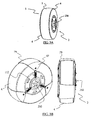
- the first embodiment proposes use of ratcheted straps (106) extending radially from the tip of a surface contact member towards the center of the wheel. These straps are generally attached to the tips of surface contact members by means of joints (97, 98), or they are extensions or integral parts of surface contact members.
- the central node (111) in this case has a plurality of securing means e.g. buckles (32) which will receive the ratcheted straps (106) coming from the surface contact members as shown in Fig. 1B .
- Fig. 1C shows a ratcheted strap (106) extending from the surface contact member which comprises a plurality of ratchets (30) on its one face, and another strap extending from the central node (111) comprising a securing means in the form of a buckle (32), and an optional sleeve (33) with an open or closed end.
- the buckle (32) draws the ratcheted strap (106) in direction D4 ( Fig. 1D ) when the user pulls the driving thumb (36) in direction K as many times as needed to adjust the tightness of the surface contact members.
- the ratcheted strap (106) is drawn as the teeth (38) of the buckle (32) drives ratchet teeth (30) of the strap (106) in direction D4 by pushing a pawl (37) up around joint F.
- the driving thumb (36) and the release thumb (35) are pivoted around joint E and move together as the user pulls the driving thumb (36) in direction K of Fig. 1E .
- Joint E and F have springs (not shown) to call back thumbs (35, 36) and the pawl (37).
- Fig. 1G shows how the ratchet teeth (30) of the strap (106) are released from the teeth (38) and pawl (37) of buckle (32) and how the system is then unfastened by pulling the strap (106) out of said buckle (32) in direction L.
- FIG. 1E shows how the ratcheted straps (106) are driven inside the buckles (32) in a way to fasten and tighten the system
- Fig. 1F shows how the ratcheted straps (106) and buckles (32) are coupled in the fastened position.
- Fig. 1G illustrates how the system can be unfastened in detail for releasing the ratcheted straps (106) from the buckles (32).
- Tightening system proposed by the present invention is also applicable to many existing anti-skid and traction enhancement devices.
- An embodiment prepared for such a case is illustrated in Fig. 4 .
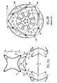
- the central tightening system of straps is shown in a free form on the right part of the drawing while shown as installed on a conventional snow chain (251) on the left part of the drawing.
- the conventional snow chain is formed of chain parts on the treaded surface of the tire (4) and connecting chain links (252) on the front and/or the rear face of the wheel (1).
- the central tightening system has a plurality of outer straps similar to those of FIG. 2B which are wrapped around the chain link (252), folded back onto themselves, tightened and secured by a fastening means, such as a buckle (32).
- Fig. 5A shows frontal view of X-shaped surface contact members in unfolded positions for two different tire diameters. Particularly, the figure is intended to illustrate how their shapes and alignments change in case of two different tire dimensions (x1, x2).
- Fig. 5B shows the front view of a system in its tightened position.
- X-shaped surface contact members are pulled towards each other obliquely in the peripheral direction (tangential to the tire) from their proximal ends which result in serious outward bulging on the surface contact member when the size of the surface contact member is not suitable to that of the tire (i.e. when the width of treaded portion of tire and/or the tire diameter is smaller than desired).
- W1 is the distance between the proximal ends (49) of a single X-shaped surface contact member (M1 or M2 or M3) under normal conditions.
- W2 is the distance between proximal ends (49) of a single X-shaped surface contact member (M1 or M2 or M3) when the device is mounted on a tire which is dimensionally not suitable (i.e. the width of tire tread portion and/or the tire diameter is smaller than desired). In such a case, W2 is smaller than W1 because the X-shaped surface contact member changes shape in order to adapt to the dimensional incompatibility between the device and the tire.
- W2 is smaller than W1 results in an outward bulging (OB) of thread portion (T) of X-shaped surface contact members (M1, M2 and M3) when mounted and tightened on the tire (4), which means a continuous slack in the device.
- proximal ends (49) of X-shaped surface contact members (M1, M2, M3) shall be outwardly stretched in direction (V1) in a way to be stretched and snugly fit on and around the periphery of the tire (1).
- V2 is the rotational direction that indicates the inward bulging of proximal ends (49) of a single X-shaped surface contact member (M1 or M2 or M3) within itself due to shortening of P1 to P2.
- "OB" is used to denote the outward bulging of X-shaped surface contact members (M1, M2 or M3) from their tread portions (T) when they are mounted on a tire.
- tread portion (T) of X-shaped surface contact members (M1, M2, M3) are even slightly wider than the width of threaded portion (7) of tire (4), and if the diameter (X2) of the tire (4) is even slightly narrower than the suitable diameter (X1) which must be used for such a system, this outward bulging (OB) will always occur.
- FIG. 7 A further alternate embodiment of the invention is shown in Fig. 7 .
- This embodiment proposes an independent central node (113) which has a plurality of arc shaped slots (114) for allowing buckles (32) or straps to move to some certain extent in the tangential direction.
- This tangential freedom of movement is used by buckles (32) located in the arc shaped slots (114) to better catch corresponding straps extending from the surface contact members by means of sliding along direction A inside said slots (114) as shown in Fig. 7 .
- This freedom provides great flexibility to the whole system against any irregular distribution of the surface contact members along the tire periphery during installation.
- connecting members are in the form of straps having Velcro® portions for tightening surface contact members.
- the Velcro® hook and Velcro® loop portions are used in place of the aforementioned ratchet teeth (30) and buckle (32).
- Surface contact members used with the central tightening system of the present invention are preferably made of flexible, durable and wear/tear/abrasion resistant polymers such as high performance polyurethane. Materials of these may further be enriched with abrasive particles (e.g. Silicon Carbide, etc.) and anti-slipping agents (e.g. Silica, etc.) for improved performance in adverse road conditions, and generally manufactured through injection molding.
- abrasive particles e.g. Silicon Carbide, etc.
- anti-slipping agents e.g. Silica, etc.
- These contact members have a mesh structure on their surface for improved traction with the ground and for better cohesion with the tire treads. Grooves provided close to the edges provide better bending and stretching for snug-fit on the treaded surface of the tire.
Landscapes
- Engineering & Computer Science (AREA)
- Mechanical Engineering (AREA)
- Tires In General (AREA)
- Clamps And Clips (AREA)
- Braking Arrangements (AREA)
- Devices For Conveying Motion By Means Of Endless Flexible Members (AREA)
- Laying Of Electric Cables Or Lines Outside (AREA)
Claims (7)
- Straffungssystem zur Verwendung in Gleitschutz- und Traktionsverbesserungsvorrichtungen, aufweisend
einen zentralen Knotenpunkt (111, 112, 113), welcher sich auf der Hauptachse der Radachse befindet, wobei der Knotenpunkt eine Vielzahl von Fortsätzen aufweist, die dazu eingerichtet sind, eine Vielzahl von sich radial erstreckenden Riemen um seine Peripherie zu fixieren und zu straffen, und zwar ohne eine Verbindung mit dem Rad aufzuweisen,
eine Vielzahl von sich radial erstreckenden flexiblen Riemen, welche an ihren ersten Enden an einem Oberflächenkontaktelement (79) und an ihren zweiten Enden an dem zentralen Knotenpunkt (111, 112, 113) befestigt sind, wobei die flexiblen Riemen gebogen sind und durch eine entsprechende Schnalle (32) geführt sind, um die Oberflächenkontaktelemente in der radialen Richtung zu straffen, dadurch gekennzeichnet dass:die Riemen entlang zumindest einer ihrer Oberflächen mit Sperrzähnen (30) ausgestattet sind, und dassdie Schnalle (32) einen Antriebszapfen (36) aufweist, welcher - wenn der Nutzer in Richtung K zieht - es dem Nutzer ermöglicht, die Straffheit des Riemens so weit wie nötig einstellen, während eine Rückwärtsbewegung des Sperrriemens mittels eines Zahnes (38) und einer Ratsche (37) der Schnalle (32) verhindert wird. - Straffungssystem zur Verwendung in Gleitschutz- und Traktionsverbesserungsvorrichtungen nach Anspruch 1, bei dem zumindest einer der Riemen zumindest einen Klettbereich zum Sichern des Riemens nach dem Straffen aufweist.
- Straffungssystem nach Anspruch 1, bei dem die Mitte des zentralen Knotenpunkts (111, 112, 113) hohl ist, um eine Installation des Straffungssystems an Naben zu ermöglichen, welche nach Außen gerichtete Vorsprünge (250) aufweisen.
- Straffungssystem nach Anspruch 1, bei dem der zentrale Knotenpunkts (111, 112, 113) eine Vielzahl von bogenförmigen Aussparungen (114) aufweist, um eine begrenzte, typischerweise weniger als 120° betragende, Winkelbewegung von Riemen oder Schnallen (32) bereitzustellen, um es zu ermöglichen, dass die Riemen oder Schnallen in Fällen einer ungleichmäßigen Verteilung von Oberflächenkontaktelementen um die Peripherie des Reifens zu ihren entsprechenden Fixierungselementen passen.
- Straffungssystem nach Anspruch 1, bei dem die Schnalle (32) einen Entriegelungszapfen (35) aufweist, welcher um ein Gelenk (E) schwenkbar ist und welche sich zusammen mit dem Antriebszapfen (36) bewegen, wenn der Nutzer den Antriebszapfen (36) in Richtung K zieht.
- Straffungssystem nach Anspruch 1, bei dem die Schnalle (32) einen Entriegelungszapfen (35) aufweist, welcher die Zähne (38) und die Ratsche (37) aus dem Sperrriemen ausklinkt, wenn in Richtung R gezogen wird.
- Gleitschutz- und Traktionsverbesserungsvorrichtung, aufweisend das Straffungssystem nach einem der vorhergehenden Ansprüche.
Priority Applications (1)
| Application Number | Priority Date | Filing Date | Title |
|---|---|---|---|
| EP06830857A EP1973756B1 (de) | 2006-01-03 | 2006-12-29 | Zentrales spannsystem für gleitschutzvorrichtungen und gleitschutzvorrichtung damit |
Applications Claiming Priority (3)
| Application Number | Priority Date | Filing Date | Title |
|---|---|---|---|
| EP06100045A EP1803592A1 (de) | 2006-01-03 | 2006-01-03 | Zentrales Spannsystem für Gleitschutzketten und Gleitschutzkette mit solch einem System |
| PCT/EP2006/070277 WO2007077204A1 (en) | 2006-01-03 | 2006-12-29 | A central tightening system for anti-skid devices and an anti-skid device having the same |
| EP06830857A EP1973756B1 (de) | 2006-01-03 | 2006-12-29 | Zentrales spannsystem für gleitschutzvorrichtungen und gleitschutzvorrichtung damit |
Publications (2)
| Publication Number | Publication Date |
|---|---|
| EP1973756A1 EP1973756A1 (de) | 2008-10-01 |
| EP1973756B1 true EP1973756B1 (de) | 2009-08-05 |
Family
ID=36609487
Family Applications (2)
| Application Number | Title | Priority Date | Filing Date |
|---|---|---|---|
| EP06100045A Withdrawn EP1803592A1 (de) | 2006-01-03 | 2006-01-03 | Zentrales Spannsystem für Gleitschutzketten und Gleitschutzkette mit solch einem System |
| EP06830857A Not-in-force EP1973756B1 (de) | 2006-01-03 | 2006-12-29 | Zentrales spannsystem für gleitschutzvorrichtungen und gleitschutzvorrichtung damit |
Family Applications Before (1)
| Application Number | Title | Priority Date | Filing Date |
|---|---|---|---|
| EP06100045A Withdrawn EP1803592A1 (de) | 2006-01-03 | 2006-01-03 | Zentrales Spannsystem für Gleitschutzketten und Gleitschutzkette mit solch einem System |
Country Status (11)
| Country | Link |
|---|---|
| US (1) | US8061397B2 (de) |
| EP (2) | EP1803592A1 (de) |
| JP (1) | JP4879280B2 (de) |
| KR (1) | KR101019552B1 (de) |
| CN (1) | CN101356068B (de) |
| AT (1) | ATE438524T1 (de) |
| CA (1) | CA2635809C (de) |
| DE (1) | DE602006008355D1 (de) |
| EA (1) | EA015553B9 (de) |
| NZ (1) | NZ570148A (de) |
| WO (1) | WO2007077204A1 (de) |
Families Citing this family (8)
| Publication number | Priority date | Publication date | Assignee | Title |
|---|---|---|---|---|
| US8720846B2 (en) * | 2009-07-03 | 2014-05-13 | Milestone Av Technologies Llc | Television safety strap |
| US8113252B2 (en) * | 2009-10-23 | 2012-02-14 | London Reil | Tire traction device with guided radial tensioning arms |
| EP2489528B1 (de) * | 2011-02-16 | 2015-08-05 | Thule Sweden AB | Antirutschvorrichtung für ein Rad |
| US11059335B2 (en) * | 2014-04-23 | 2021-07-13 | David Martin | Tire traction devices |
| US9981511B2 (en) | 2014-04-23 | 2018-05-29 | David Martin | Tire traction devices |
| CN104773041A (zh) * | 2015-04-15 | 2015-07-15 | 东北林业大学 | 一种便携式汽车脱陷器 |
| JP2017165152A (ja) * | 2016-03-14 | 2017-09-21 | 株式会社クリーン企画 | タイヤ滑り止め具 |
| JP2024066115A (ja) * | 2022-11-01 | 2024-05-15 | 株式会社カーメイト | タイヤ滑り止め装置の緊締手段 |
Family Cites Families (37)
| Publication number | Priority date | Publication date | Assignee | Title |
|---|---|---|---|---|
| US982630A (en) * | 1910-06-30 | 1911-01-24 | William M Paul | Antiskidding-armor for tires. |
| US1768370A (en) * | 1929-07-08 | 1930-06-24 | Charles C Pearson | Nonskid overshoe |
| US2066368A (en) * | 1935-04-25 | 1937-01-05 | William H Snyder | Antiskid device |
| US2174345A (en) * | 1938-04-04 | 1939-09-26 | Stanley L Worthing | Traction device for vehicle wheels |
| US2267242A (en) * | 1939-01-24 | 1941-12-23 | William J Lutey | Resilient cross band for pneumatic tires |
| US2270692A (en) * | 1941-02-05 | 1942-01-20 | Thomas J Stanton | Antiskid device |
| US2433605A (en) * | 1945-04-04 | 1947-12-30 | Faulds George | Vehicle wheel |
| US2470607A (en) * | 1947-06-26 | 1949-05-17 | Theodore D Dritz | Traction device |
| US2687160A (en) * | 1951-05-03 | 1954-08-24 | Harold A Norton | Antiskid device for tires |
| US2685903A (en) * | 1951-05-04 | 1954-08-10 | William J Lutey | Rubber nonskid crossband |
| US2746508A (en) * | 1952-05-07 | 1956-05-22 | Hartwell T Doughty | Tire lug assembly |
| US3091274A (en) * | 1960-12-19 | 1963-05-28 | Harold J Winkelspecht | Traction device |
| US4334569A (en) * | 1979-08-03 | 1982-06-15 | Dayco Corporation | Traction assembly |
| DE3227872A1 (de) * | 1982-07-26 | 1984-01-26 | Walter 6479 Schotten Hortmann | Gleitschutz-reifenumspannung fuer kraftfahrzeuge |
| US4528700A (en) * | 1984-04-16 | 1985-07-16 | Lyman Johnston | Support belt and buckle therefor |
| JPS60255511A (ja) | 1984-05-31 | 1985-12-17 | Sumitomo Wiring Syst Ltd | タイヤのすべり止め装置 |
| US4567096A (en) | 1985-03-21 | 1986-01-28 | Piltingsrud Douglas H | Hydrated alumina binder system |
| JPS6251008A (ja) * | 1985-08-30 | 1987-03-05 | Hitachi Ltd | デ−タ書込み回路 |
| IT206663Z2 (it) * | 1985-09-06 | 1987-10-01 | Olivieri Icaro & C | Dispositivo di allacciatura a componenti articolati, particolarmente per articoli sportivi. |
| JPS6251008U (de) * | 1985-09-19 | 1987-03-30 | ||
| JPH0531926Y2 (de) * | 1986-12-27 | 1993-08-17 | ||
| FR2626532B1 (fr) * | 1988-02-02 | 1991-02-08 | Taunay Maurice | Dispositif d'antipatinage pour roues de vehicules automobiles |
| US4918790A (en) * | 1989-05-12 | 1990-04-24 | Soniform, Inc. | Cam buckle |
| JPH0448004A (ja) * | 1990-06-15 | 1992-02-18 | Toshiba Corp | Fe基軟磁性合金粉末とその製造方法およびそれを用いた圧粉磁心 |
| JP2938139B2 (ja) * | 1990-05-21 | 1999-08-23 | 毅 池田 | 滑り止め装置 |
| JPH0448004U (de) * | 1990-08-30 | 1992-04-23 | ||
| JP2875045B2 (ja) | 1991-04-26 | 1999-03-24 | 横浜ゴム株式会社 | タイヤ滑り止め装置 |
| US5284196A (en) * | 1993-03-11 | 1994-02-08 | Nielsen Charles R | Tire chain tightening apparatus |
| TW368805U (en) * | 1998-08-27 | 1999-09-01 | Taiwan Ind Fastener Corp | Adjustable fastener |
| EP1216161A1 (de) * | 1999-08-20 | 2002-06-26 | Jong Gil Kim | Reifenkette |
| CN2421188Y (zh) * | 2000-04-06 | 2001-02-28 | 上海纽福克斯汽车配件有限公司 | 防滑链松紧自动调节器 |
| KR200254405Y1 (ko) | 2001-09-01 | 2001-11-23 | 김세길 | 자동차용 스노우 체인 |
| KR100470206B1 (ko) | 2002-01-17 | 2005-02-22 | 이은순 | 타이어 미끄럼 방지장치 |
| KR200289448Y1 (ko) | 2002-06-14 | 2002-09-16 | 하동호 | 우레탄 체인 |
| DE20315855U1 (de) * | 2003-10-15 | 2005-02-24 | Confon Ag | Gleitschutzvorrichtung, insbesondere für luftbereifte Fahrzeugräder, auf Eis- und Schneeflächen |
| JP2005193765A (ja) * | 2004-01-07 | 2005-07-21 | Soft99 Corporation | タイヤ滑止め装置用の引締め具 |
| US20060225254A1 (en) * | 2005-04-07 | 2006-10-12 | Yang-Chen Fu | Tire chain assembly having a tension adjustment function |
-
2006
- 2006-01-03 EP EP06100045A patent/EP1803592A1/de not_active Withdrawn
- 2006-12-29 CA CA2635809A patent/CA2635809C/en not_active Expired - Fee Related
- 2006-12-29 US US12/159,934 patent/US8061397B2/en not_active Expired - Fee Related
- 2006-12-29 NZ NZ570148A patent/NZ570148A/en not_active IP Right Cessation
- 2006-12-29 KR KR1020087019030A patent/KR101019552B1/ko not_active Expired - Fee Related
- 2006-12-29 EP EP06830857A patent/EP1973756B1/de not_active Not-in-force
- 2006-12-29 AT AT06830857T patent/ATE438524T1/de active
- 2006-12-29 WO PCT/EP2006/070277 patent/WO2007077204A1/en not_active Ceased
- 2006-12-29 CN CN200680050331XA patent/CN101356068B/zh not_active Expired - Fee Related
- 2006-12-29 EA EA200870143A patent/EA015553B9/ru not_active IP Right Cessation
- 2006-12-29 JP JP2008548990A patent/JP4879280B2/ja not_active Expired - Fee Related
- 2006-12-29 DE DE602006008355T patent/DE602006008355D1/de active Active
Also Published As
| Publication number | Publication date |
|---|---|
| WO2007077204A1 (en) | 2007-07-12 |
| EA200870143A1 (ru) | 2009-04-28 |
| CN101356068B (zh) | 2010-05-19 |
| NZ570148A (en) | 2011-02-25 |
| JP2009522164A (ja) | 2009-06-11 |
| EP1973756A1 (de) | 2008-10-01 |
| KR20080087879A (ko) | 2008-10-01 |
| KR101019552B1 (ko) | 2011-03-08 |
| EP1803592A1 (de) | 2007-07-04 |
| JP4879280B2 (ja) | 2012-02-22 |
| US8061397B2 (en) | 2011-11-22 |
| CA2635809A1 (en) | 2007-07-12 |
| US20090151834A1 (en) | 2009-06-18 |
| EA015553B1 (ru) | 2011-08-30 |
| ATE438524T1 (de) | 2009-08-15 |
| CA2635809C (en) | 2011-07-12 |
| CN101356068A (zh) | 2009-01-28 |
| EA015553B9 (ru) | 2012-01-30 |
| DE602006008355D1 (de) | 2009-09-17 |
Similar Documents
| Publication | Publication Date | Title |
|---|---|---|
| US20160368334A1 (en) | Tire traction device | |
| EP1973756B1 (de) | Zentrales spannsystem für gleitschutzvorrichtungen und gleitschutzvorrichtung damit | |
| EP0474732B1 (de) | Diagonale reifenkette | |
| US5236025A (en) | Diagonal tire chains with side cable fasteners | |
| JP5951871B1 (ja) | タイヤ滑止装置およびタイヤ滑止装置用本体 | |
| US5837075A (en) | Anti-skid chain | |
| US4042000A (en) | Device for tire chains | |
| JPS6390409A (ja) | タイヤ滑り止め装置の取付方法 | |
| US9776464B2 (en) | Anti-skid device for tire and main body for anti-skid device for tire | |
| JPH0510243B2 (de) | ||
| JPH08332815A (ja) | 自動車車輪の滑走防止装置 | |
| JPH0257411A (ja) | 自動車用タイヤ滑り止めの締結装置 | |
| JP3011683U (ja) | 自動車用タイヤ滑り止め装置 | |
| JP3124113U (ja) | タイヤ用滑止具 | |
| JPH0448963Y2 (de) | ||
| JPH034564Y2 (de) | ||
| JP2002036839A (ja) | タイヤ滑止具 | |
| KR20070118689A (ko) | 탄성 체결 수단을 포함하는 스노우 체인 부착 시스템 | |
| EP1089887A1 (de) | Gleitschutzkette mit zigzag muster kreuzketteelement veränderlicher längen | |
| JPH0560909U (ja) | タイヤ滑り止め装置のロープフック | |
| JP2000313214A (ja) | 自動車用タイヤ滑り止め装置 | |
| JPH0572507U (ja) | タイヤの滑り止め装置 | |
| JPH06166312A (ja) | タイヤ滑り止め用バンド | |
| JPH08300916A (ja) | タイヤ滑り止め装置の締結具 | |
| JPH0526514U (ja) | タイヤの滑り止め装置 |
Legal Events
| Date | Code | Title | Description |
|---|---|---|---|
| PUAI | Public reference made under article 153(3) epc to a published international application that has entered the european phase |
Free format text: ORIGINAL CODE: 0009012 |
|
| 17P | Request for examination filed |
Effective date: 20080804 |
|
| AK | Designated contracting states |
Kind code of ref document: A1 Designated state(s): AT BE BG CH CY CZ DE DK EE ES FI FR GB GR HU IE IS IT LI LT LU LV MC NL PL PT RO SE SI SK TR |
|
| GRAP | Despatch of communication of intention to grant a patent |
Free format text: ORIGINAL CODE: EPIDOSNIGR1 |
|
| DAX | Request for extension of the european patent (deleted) | ||
| GRAS | Grant fee paid |
Free format text: ORIGINAL CODE: EPIDOSNIGR3 |
|
| GRAA | (expected) grant |
Free format text: ORIGINAL CODE: 0009210 |
|
| AK | Designated contracting states |
Kind code of ref document: B1 Designated state(s): AT BE BG CH CY CZ DE DK EE ES FI FR GB GR HU IE IS IT LI LT LU LV MC NL PL PT RO SE SI SK TR |
|
| REG | Reference to a national code |
Ref country code: GB Ref legal event code: FG4D |
|
| REG | Reference to a national code |
Ref country code: CH Ref legal event code: EP |
|
| REG | Reference to a national code |
Ref country code: IE Ref legal event code: FG4D |
|
| REF | Corresponds to: |
Ref document number: 602006008355 Country of ref document: DE Date of ref document: 20090917 Kind code of ref document: P |
|
| REG | Reference to a national code |
Ref country code: CH Ref legal event code: NV Representative=s name: PETER RUTZ |
|
| REG | Reference to a national code |
Ref country code: SE Ref legal event code: TRGR |
|
| LTIE | Lt: invalidation of european patent or patent extension |
Effective date: 20090805 |
|
| PG25 | Lapsed in a contracting state [announced via postgrant information from national office to epo] |
Ref country code: ES Free format text: LAPSE BECAUSE OF FAILURE TO SUBMIT A TRANSLATION OF THE DESCRIPTION OR TO PAY THE FEE WITHIN THE PRESCRIBED TIME-LIMIT Effective date: 20091116 Ref country code: FI Free format text: LAPSE BECAUSE OF FAILURE TO SUBMIT A TRANSLATION OF THE DESCRIPTION OR TO PAY THE FEE WITHIN THE PRESCRIBED TIME-LIMIT Effective date: 20090805 Ref country code: LT Free format text: LAPSE BECAUSE OF FAILURE TO SUBMIT A TRANSLATION OF THE DESCRIPTION OR TO PAY THE FEE WITHIN THE PRESCRIBED TIME-LIMIT Effective date: 20090805 Ref country code: IS Free format text: LAPSE BECAUSE OF FAILURE TO SUBMIT A TRANSLATION OF THE DESCRIPTION OR TO PAY THE FEE WITHIN THE PRESCRIBED TIME-LIMIT Effective date: 20091205 |
|
| NLV1 | Nl: lapsed or annulled due to failure to fulfill the requirements of art. 29p and 29m of the patents act | ||
| PG25 | Lapsed in a contracting state [announced via postgrant information from national office to epo] |
Ref country code: NL Free format text: LAPSE BECAUSE OF FAILURE TO SUBMIT A TRANSLATION OF THE DESCRIPTION OR TO PAY THE FEE WITHIN THE PRESCRIBED TIME-LIMIT Effective date: 20090805 Ref country code: PL Free format text: LAPSE BECAUSE OF FAILURE TO SUBMIT A TRANSLATION OF THE DESCRIPTION OR TO PAY THE FEE WITHIN THE PRESCRIBED TIME-LIMIT Effective date: 20090805 Ref country code: LV Free format text: LAPSE BECAUSE OF FAILURE TO SUBMIT A TRANSLATION OF THE DESCRIPTION OR TO PAY THE FEE WITHIN THE PRESCRIBED TIME-LIMIT Effective date: 20090805 Ref country code: SI Free format text: LAPSE BECAUSE OF FAILURE TO SUBMIT A TRANSLATION OF THE DESCRIPTION OR TO PAY THE FEE WITHIN THE PRESCRIBED TIME-LIMIT Effective date: 20090805 |
|
| PG25 | Lapsed in a contracting state [announced via postgrant information from national office to epo] |
Ref country code: PT Free format text: LAPSE BECAUSE OF FAILURE TO SUBMIT A TRANSLATION OF THE DESCRIPTION OR TO PAY THE FEE WITHIN THE PRESCRIBED TIME-LIMIT Effective date: 20091205 Ref country code: BG Free format text: LAPSE BECAUSE OF FAILURE TO SUBMIT A TRANSLATION OF THE DESCRIPTION OR TO PAY THE FEE WITHIN THE PRESCRIBED TIME-LIMIT Effective date: 20091105 |
|
| PG25 | Lapsed in a contracting state [announced via postgrant information from national office to epo] |
Ref country code: EE Free format text: LAPSE BECAUSE OF FAILURE TO SUBMIT A TRANSLATION OF THE DESCRIPTION OR TO PAY THE FEE WITHIN THE PRESCRIBED TIME-LIMIT Effective date: 20090805 Ref country code: RO Free format text: LAPSE BECAUSE OF FAILURE TO SUBMIT A TRANSLATION OF THE DESCRIPTION OR TO PAY THE FEE WITHIN THE PRESCRIBED TIME-LIMIT Effective date: 20090805 Ref country code: DK Free format text: LAPSE BECAUSE OF FAILURE TO SUBMIT A TRANSLATION OF THE DESCRIPTION OR TO PAY THE FEE WITHIN THE PRESCRIBED TIME-LIMIT Effective date: 20090805 Ref country code: CZ Free format text: LAPSE BECAUSE OF FAILURE TO SUBMIT A TRANSLATION OF THE DESCRIPTION OR TO PAY THE FEE WITHIN THE PRESCRIBED TIME-LIMIT Effective date: 20090805 |
|
| PG25 | Lapsed in a contracting state [announced via postgrant information from national office to epo] |
Ref country code: SK Free format text: LAPSE BECAUSE OF FAILURE TO SUBMIT A TRANSLATION OF THE DESCRIPTION OR TO PAY THE FEE WITHIN THE PRESCRIBED TIME-LIMIT Effective date: 20090805 |
|
| PLBE | No opposition filed within time limit |
Free format text: ORIGINAL CODE: 0009261 |
|
| STAA | Information on the status of an ep patent application or granted ep patent |
Free format text: STATUS: NO OPPOSITION FILED WITHIN TIME LIMIT |
|
| PG25 | Lapsed in a contracting state [announced via postgrant information from national office to epo] |
Ref country code: BE Free format text: LAPSE BECAUSE OF FAILURE TO SUBMIT A TRANSLATION OF THE DESCRIPTION OR TO PAY THE FEE WITHIN THE PRESCRIBED TIME-LIMIT Effective date: 20090805 |
|
| 26N | No opposition filed |
Effective date: 20100507 |
|
| PG25 | Lapsed in a contracting state [announced via postgrant information from national office to epo] |
Ref country code: MC Free format text: LAPSE BECAUSE OF NON-PAYMENT OF DUE FEES Effective date: 20100701 |
|
| PG25 | Lapsed in a contracting state [announced via postgrant information from national office to epo] |
Ref country code: GR Free format text: LAPSE BECAUSE OF FAILURE TO SUBMIT A TRANSLATION OF THE DESCRIPTION OR TO PAY THE FEE WITHIN THE PRESCRIBED TIME-LIMIT Effective date: 20091106 Ref country code: IE Free format text: LAPSE BECAUSE OF NON-PAYMENT OF DUE FEES Effective date: 20091229 |
|
| PG25 | Lapsed in a contracting state [announced via postgrant information from national office to epo] |
Ref country code: LU Free format text: LAPSE BECAUSE OF NON-PAYMENT OF DUE FEES Effective date: 20091229 |
|
| PGRI | Patent reinstated in contracting state [announced from national office to epo] |
Ref country code: IT Effective date: 20110501 |
|
| PG25 | Lapsed in a contracting state [announced via postgrant information from national office to epo] |
Ref country code: HU Free format text: LAPSE BECAUSE OF FAILURE TO SUBMIT A TRANSLATION OF THE DESCRIPTION OR TO PAY THE FEE WITHIN THE PRESCRIBED TIME-LIMIT Effective date: 20100206 |
|
| PG25 | Lapsed in a contracting state [announced via postgrant information from national office to epo] |
Ref country code: CY Free format text: LAPSE BECAUSE OF FAILURE TO SUBMIT A TRANSLATION OF THE DESCRIPTION OR TO PAY THE FEE WITHIN THE PRESCRIBED TIME-LIMIT Effective date: 20090805 |
|
| REG | Reference to a national code |
Ref country code: FR Ref legal event code: PLFP Year of fee payment: 10 |
|
| PGFP | Annual fee paid to national office [announced via postgrant information from national office to epo] |
Ref country code: CH Payment date: 20160630 Year of fee payment: 10 Ref country code: GB Payment date: 20160630 Year of fee payment: 10 |
|
| PGFP | Annual fee paid to national office [announced via postgrant information from national office to epo] |
Ref country code: AT Payment date: 20160701 Year of fee payment: 10 Ref country code: FR Payment date: 20160630 Year of fee payment: 10 Ref country code: SE Payment date: 20160630 Year of fee payment: 10 |
|
| PGFP | Annual fee paid to national office [announced via postgrant information from national office to epo] |
Ref country code: IT Payment date: 20160630 Year of fee payment: 10 Ref country code: DE Payment date: 20160630 Year of fee payment: 10 |
|
| PGFP | Annual fee paid to national office [announced via postgrant information from national office to epo] |
Ref country code: TR Payment date: 20141229 Year of fee payment: 9 |
|
| REG | Reference to a national code |
Ref country code: DE Ref legal event code: R119 Ref document number: 602006008355 Country of ref document: DE |
|
| REG | Reference to a national code |
Ref country code: CH Ref legal event code: PL |
|
| REG | Reference to a national code |
Ref country code: SE Ref legal event code: EUG |
|
| REG | Reference to a national code |
Ref country code: AT Ref legal event code: MM01 Ref document number: 438524 Country of ref document: AT Kind code of ref document: T Effective date: 20161229 |
|
| GBPC | Gb: european patent ceased through non-payment of renewal fee |
Effective date: 20161229 |
|
| PG25 | Lapsed in a contracting state [announced via postgrant information from national office to epo] |
Ref country code: SE Free format text: LAPSE BECAUSE OF NON-PAYMENT OF DUE FEES Effective date: 20161230 |
|
| REG | Reference to a national code |
Ref country code: FR Ref legal event code: ST Effective date: 20170831 |
|
| PG25 | Lapsed in a contracting state [announced via postgrant information from national office to epo] |
Ref country code: FR Free format text: LAPSE BECAUSE OF NON-PAYMENT OF DUE FEES Effective date: 20170102 Ref country code: LI Free format text: LAPSE BECAUSE OF NON-PAYMENT OF DUE FEES Effective date: 20161231 Ref country code: AT Free format text: LAPSE BECAUSE OF NON-PAYMENT OF DUE FEES Effective date: 20161229 Ref country code: CH Free format text: LAPSE BECAUSE OF NON-PAYMENT OF DUE FEES Effective date: 20161231 Ref country code: IT Free format text: LAPSE BECAUSE OF NON-PAYMENT OF DUE FEES Effective date: 20161229 |
|
| PG25 | Lapsed in a contracting state [announced via postgrant information from national office to epo] |
Ref country code: DE Free format text: LAPSE BECAUSE OF NON-PAYMENT OF DUE FEES Effective date: 20170701 Ref country code: GB Free format text: LAPSE BECAUSE OF NON-PAYMENT OF DUE FEES Effective date: 20161229 |
|
| PG25 | Lapsed in a contracting state [announced via postgrant information from national office to epo] |
Ref country code: TR Free format text: LAPSE BECAUSE OF NON-PAYMENT OF DUE FEES Effective date: 20161229 |