EP1986909B1 - Karosseriedichtung lenksäulendurchführung - Google Patents
Karosseriedichtung lenksäulendurchführung Download PDFInfo
- Publication number
- EP1986909B1 EP1986909B1 EP07721928A EP07721928A EP1986909B1 EP 1986909 B1 EP1986909 B1 EP 1986909B1 EP 07721928 A EP07721928 A EP 07721928A EP 07721928 A EP07721928 A EP 07721928A EP 1986909 B1 EP1986909 B1 EP 1986909B1
- Authority
- EP
- European Patent Office
- Prior art keywords
- sealing system
- steering housing
- seal
- steering
- sealing
- Prior art date
- Legal status (The legal status is an assumption and is not a legal conclusion. Google has not performed a legal analysis and makes no representation as to the accuracy of the status listed.)
- Ceased
Links
- 238000007789 sealing Methods 0.000 claims description 55
- 239000004033 plastic Substances 0.000 claims description 7
- 229920003023 plastic Polymers 0.000 claims description 7
- 238000009434 installation Methods 0.000 claims description 2
- 210000001331 nose Anatomy 0.000 description 23
- 238000005192 partition Methods 0.000 description 12
- 230000000903 blocking effect Effects 0.000 description 4
- 230000000694 effects Effects 0.000 description 4
- 230000007613 environmental effect Effects 0.000 description 4
- XLYOFNOQVPJJNP-UHFFFAOYSA-N water Substances O XLYOFNOQVPJJNP-UHFFFAOYSA-N 0.000 description 3
- VGGSQFUCUMXWEO-UHFFFAOYSA-N Ethene Chemical compound C=C VGGSQFUCUMXWEO-UHFFFAOYSA-N 0.000 description 2
- 239000005977 Ethylene Substances 0.000 description 2
- 229910000831 Steel Inorganic materials 0.000 description 2
- 238000010586 diagram Methods 0.000 description 2
- 230000002349 favourable effect Effects 0.000 description 2
- 230000003993 interaction Effects 0.000 description 2
- 238000004519 manufacturing process Methods 0.000 description 2
- 229910052751 metal Inorganic materials 0.000 description 2
- 239000002184 metal Substances 0.000 description 2
- 239000010959 steel Substances 0.000 description 2
- 229920001169 thermoplastic Polymers 0.000 description 2
- 229920002725 thermoplastic elastomer Polymers 0.000 description 2
- 239000004416 thermosoftening plastic Substances 0.000 description 2
- 230000008719 thickening Effects 0.000 description 2
- 229910052782 aluminium Inorganic materials 0.000 description 1
- XAGFODPZIPBFFR-UHFFFAOYSA-N aluminium Chemical compound [Al] XAGFODPZIPBFFR-UHFFFAOYSA-N 0.000 description 1
- 150000001875 compounds Chemical class 0.000 description 1
- 238000013016 damping Methods 0.000 description 1
- 230000001066 destructive effect Effects 0.000 description 1
- 239000007789 gas Substances 0.000 description 1
- 238000001746 injection moulding Methods 0.000 description 1
- 238000003780 insertion Methods 0.000 description 1
- 230000037431 insertion Effects 0.000 description 1
- 238000007689 inspection Methods 0.000 description 1
- 238000012423 maintenance Methods 0.000 description 1
- 238000009417 prefabrication Methods 0.000 description 1
- 239000007921 spray Substances 0.000 description 1
Images

Classifications
-
- B—PERFORMING OPERATIONS; TRANSPORTING
- B62—LAND VEHICLES FOR TRAVELLING OTHERWISE THAN ON RAILS
- B62D—MOTOR VEHICLES; TRAILERS
- B62D1/00—Steering controls, i.e. means for initiating a change of direction of the vehicle
- B62D1/02—Steering controls, i.e. means for initiating a change of direction of the vehicle vehicle-mounted
- B62D1/16—Steering columns
Definitions
- the invention relates to a sealing system for sealing an opening leading into an interior of a motor vehicle for carrying out a steering device, which has a steering housing.
- Such sealing systems are known for example for performing steering devices or steering columns by a partition between an engine compartment and the vehicle interior of a motor vehicle.
- the opening is normally located in a footwell area on the driver's side of the motor vehicle (see also FIG. 1 ). This opening must be sealed so that environmental influences such as water, noise or the like can not affect the driver, or can get into the interior.
- this seals were used, which are designed as ring seals, so have an opening in the middle through which a steering gear extension and a pinion shaft is passed.
- the seal itself is in engagement with the partition wall.
- the seal can be plugged onto the extension or on the pinion shaft.
- a disadvantage of the known arrangement is that when attaching the seal as such utmost care must be taken, since it must be placed exactly on the steering linkage, so that a seal of the opening can be done properly. Furthermore, it is disadvantageous that a slippage of the seal on the linkage during operation of the vehicle is possible, so that insufficient sealing effects can occur. For example, then water can enter the interior.
- US 20040256849 A1 discloses a sealing system according to the preamble of claim 1.
- EP 0968900 A1 discloses a frictional connection between a steering housing and a sealing system.
- the DE 25 13 050 discloses a steering column switch for motor vehicles.
- a bearing sleeve On a switch housing, a bearing sleeve is arranged, which carries circumferentially distributed lugs.
- the lugs are in L-shaped bayonet lock receptacles on the front side a steering tube inserted and fixed by rotation of the bearing sleeve.
- a detent spring On the bearing sleeve, a detent spring is recessed with locking lug, which engages after the rotation of the bearing sleeve in an opening of the steering tube.
- the DE 39 23 982 A1 relates to an energy absorbing device on the steering device of a motor vehicle with a pressure ring.
- a guide tube is locked like a bayonet with a bearing housing.
- the DE 196 32 431 deals with an arrangement for sealing an opening in a body wall, is passed through the pinion shaft of a steering gear.
- the seal assembly essentially comprises a bellows, a guide body and a counter body.
- the guide body and the counter body are coupled with each other like a bayonet.
- the invention has for its object to improve a sealing system of the type mentioned by simple means to the effect that this remains stationary even after a long period of operation of the motor vehicle, the sealing system should also be easy to install at the same time.
- connection in the context of the invention, a compound is considered, which prevents accidental release of the two standing in mutual engagement connection partner.
- the two connection partners For intentional release of the connection, the two connection partners must first be disengaged, so that the connection is non-destructive solvable.
- the seal or the sealing system on the Apply steering housing is fixed in a stable position due to the frictional connection with the steering housing, whereby slipping is avoided even after a long period of operation of the motor vehicle.
- the steering housing is assigned a nose on diametrically opposite sides.
- the noses have a height of preferably two to three millimeters, wherein the two lugs may preferably be designed differently in their dimension.
- the noses can be cylindrical in shape with different diameters and different heights.
- a second guide channel would be available, which is adapted to the particular configuration of the corresponding nose. Due to the different design of the lugs or guide channels ensures that the sealing system in conjunction with the correspondingly adapted guide channel in a single mounting position with the steering gear is connectable. This is advantageous because the opening in the partition wall is usually oval or rotationally asymmetric. The only possible mounting position is taken into account, so that the opening is always covered by the sealing system.
- the sealing system has a frame which is surrounded by a seal.
- the seal is preferably applied by injection molding on the frame.
- the seal consists for example of a rubber-like plastic, and projects beyond the frame with extensions in the direction of the steering housing.
- the extensions can also be referred to as lips, wherein these rest against the steering housing.
- the frame has a substantially funnel-shaped configuration with a fastening region and an abutment region.
- the mounting portion is adapted to the configuration of the steering housing, and has the, of course, each nose is associated with a corresponding guide channel.
- the attachment area merges into the contact area, which bears sealingly against the partition wall or can be sealingly connected.
- the investment area to the embodiment of Adjusted opening in the partition so that it is always sufficiently sealable.
- the seal is made of a rubber-like plastic, preferably a thermoplastic elastomer, particularly preferably a thermoplastic ethylene.
- a thermoplastic elastomer particularly preferably a thermoplastic ethylene.
- Such plastics are temperature stable against occurring in the engine compartment, ie in the partition wall, temperatures of 120 ° C as a continuous load or 135 ° C as a short-term load and at the same time achieve a sufficient seal against environmental influences such as moisture / moisture, gases, dirt, etc. and noise or Vibrations (Noise Vibration Harshness (NVH)).
- a durability of the seal of, for example, more than 240000km mileage of the motor vehicle is reached, the sealing system over the entire mileage of the motor vehicle stable in position, so is secured against slipping on the steering housing and always seals the opening sufficiently.
- the frame is made of a hard plastic or light metal, more preferably aluminum or a combination thereof.
- the one or more guide channels each having the blocking element whereby the nose (s) is held stationary after reaching a desired position within the receiving area, and it is possible to apply the seal defined, since the exceeding of the locking element for the assembling person audible, for example audible.
- the steering housing is a metal housing, which is particularly preferably a steel integral housing.
- On such housings can be easily arrange the at least one nose.
- the at least one lug is advantageously a pin located on the steering housing, which is particularly preferably an integral part of the steering housing and is produced by deep drawing. Deep drawing allows the production of low-maintenance joints in connection with the seal, ensuring that the service life of the components is also designed for high operating times or mileage of motor vehicles.
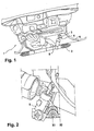
- FIG. 1 shows a perspective view of an engine compartment 1 of a motor vehicle.
- a steering gear 2 is by means of a pinion shaft 3 through an opening 4 in a partition wall 6 in a not shown interior of the Motor vehicle led.
- the partition wall 6 separates the engine compartment 1 from the interior, not shown, and may also be referred to as a bulkhead.
- the pinion shaft 3 is assigned a thickening 7.
- the thickening 7 is arranged slightly below the opening 4 ( FIG. 2 ).
- the pinion shaft 3 transmits steering movements (eg mechanical rotation) of a steering wheel, not shown, to the steering gear 2.
- the pinion shaft 3 opens with its lower end in a steering housing 8.
- the steering housing 8 is made of steel, for example.
- the opening 4 is executed with an exemplary opening amount, which is exemplified by the two lines X1 and X2.
- FIG. 3 shows a schematic diagram of a sealing system 9 for sealing the opening 4 and the partition 6 to the steering housing. 8
- the steering housing 8 is in FIG. 3 shown in a side view, and has at least one lateral nose 10. On the diametrically opposite side of the steering housing 9, not shown, also a nose can be arranged.
- the nose 10 has a height of about two to three millimeters, wherein the two lugs 10 may be different in dimension.
- the lugs 10 may be cylindrically shaped with different diameters and heights.
- the sealing system 9 has a frame 11 which is surrounded by a seal 12.
- the gasket 12 may be spray applied to the frame 11, and is e.g. of a rubbery plastic, preferably a thermoplastic elastomer, or a thermoplastic ethylene.
- the seal 12 projects beyond the frame 11 with extensions 13, which may also be referred to as lips, in the direction of the steering housing 8, so that the extensions 13 bear sealingly against the steering housing 8 with their free ends.
- the sealing system 9 is sealed to the steering housing 8.
- the frame 11 has a guide channel 14.
- the guide channel 14 extends from its insertion opening 16 in the illustrated embodiment from a lower plane of the drawing extending obliquely upward in the direction of the line X.
- the guide channel 14 opens into a receiving area 17, which is designed substantially square in side view.
- lower wall 18 of the guide channel 14 merges at its upper end 19 in a substantially horizontal wall portion 21, which merges into a wall portion 22 inclined to the lower wall 18 opposite.
- the inclined wall portion 22 extends from the horizontal wall portion 21 inclined toward the lower plane of the drawing and in the direction of the line X, and merges into a lower, horizontal wall portion 23 of the receiving area 17.
- the inclined wall portion may also be referred to as a blocking element 24, and forms a kind of elevation or step.
- the nose 10 is guided by the guide channel 14 to the receiving area 17, wherein the nose 10 is introduced via the increase or level in the receiving area 17. After passing the increase or level, the nose 10 is easily audible, for example, audibly recorded in the receiving area 17.
- the nose 10 rests with a part of its circumference on the locking element 24 in a desired position, which is easy to imagine that the locking element 24 prevents unwanted loosening of the nose 10 from the receiving area 17.
- the sealing system 9 is frictionally connected to the steering housing 8.
- To connect the sealing system 9 is attached to the steering housing 8 and according to the course of the guide channel 14 following forced twisted. Above the nose 10, a free space is formed to the wall of the receiving area 17, so that there is sufficient space for the intentional release of frictionally positive connection.
- the second nose 10 is arranged, which is performed differently to the illustrated nose 10, for example, with a larger diameter.
- the sealing system 9 has a guide channel 14 adapted thereto Receiving area 17, which has a correspondingly executed blocking element 24.
- the frame 11 thus represents a bulkhead or bulkhead seal, which is attachable to the nose 10 and rotatable, so that the nose 10 is fixed in this.
- the sealing system 9 can be connected only in a single predetermined position and direction with the steering housing 8.
- the sealing system 9 extends from the steering housing 8 in the direction of the partition wall 6 or to the bulkhead and is here connected in a suitable manner with this, for example glued.
- FIG. 4 is a sectional view taken along the line XX FIG. 3 shown.
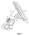
- FIG. 5 shows that the sealing system 9, for example, in a substantially funnel shape of the steering housing 8 in the direction of in FIG. 5 Not shown partition extends to seal the opening here against environmental influences.
- the sealing system 9 has adapted to the steering housing 8 mounting portion 26 and adapted to the opening 4 contact area 27.
- the adapted to the lugs 10 guide channels 14 are arranged.
- a type of sealing lip 28 is arranged, which projects slightly beyond the sealing system 9 at the top. With the sealing lip 28, the sealing system 9 can sealingly engage in the opening 4, or sealingly abut the periphery. It is conceivable that the sealing lip 28 is flexible or compliant.
- the engine compartment of the motor vehicle is sufficiently sealed, for example, against water or heat to the interior. Furthermore, the advantageous embodiment makes it possible to improve when the motor vehicle has e.g. used in off-road terrain, while also reducing noise pollution.
- a further advantage is that no relative movements of the bulkhead seal to the pinion shaft 3 occur. Because the pinion shaft 3 is completely surrounded by the sealing system 9 in the engine compartment ( FIG. 5 ). The pinion shaft 3 and the sealing system 9 are seen separated from each other, so that a seal to a rotating component (pinion shaft 3) is eliminated. It is also favorable that the embodiment according to the invention is able to absorb dynamic relative movements of the steering gear to the body. For example, tensile and compressive forces and rotational forces can be absorbed without affecting the sealing effect.
- the bulkhead seal remains even after a long service life of the motor vehicle at its once installed location, unless inspections require replacement.
- the sealing system 9 Due to the interaction of the nose and the lugs with the sealing system 9 and the guide channel 14, the sealing system 9 is easily plugged and rotatably connected to the steering housing 8 connectable, even with a prefabrication a sufficient connection is provided against unintentional release is secured.
- the sealing system 9 can be prefabricated at an external location with the steering housing 8 and transported as a unit to the installation site.
Landscapes
- Engineering & Computer Science (AREA)
- Chemical & Material Sciences (AREA)
- Combustion & Propulsion (AREA)
- Transportation (AREA)
- Mechanical Engineering (AREA)
- Steering Controls (AREA)
- Power Steering Mechanism (AREA)
- Gasket Seals (AREA)
- Body Structure For Vehicles (AREA)
Description
- Die Erfindung betrifft ein Dichtungssystem zum Abdichten einer in einen Innenraum eines Kraftfahrzeugs führenden Öffnung zur Durchführung einer Lenkeinrichtung, die ein Lenkgehäuse aufweist.
- Derartige Dichtungssysteme sind beispielsweise zum Durchführen von Lenkeinrichtungen bzw. Lenksäulen durch eine Trennwand zwischen einem Motorraum und dem Fahrzeuginnenraum eines Kraftfahrzeugs bekannt. Die Öffnung befindet sich normalerweise in einem Fußraumbereich auf der Fahrerseite des Kraftfahrzeuges (siehe auch
Figur 1 ). Diese Öffnung muss abgedichtet werden, damit Umwelteinflüsse wie Wasser, Lärm oder dergleichen nicht auf den Fahrer einwirken können, oder in den Innenraum gelangen können. - Bisher wurden hierfür Dichtungen verwendet, die als Ringdichtungen ausgeführt sind, also eine Öffnung in der Mitte aufweisen, durch die eine Lenkgetriebeverlängerung bzw. ein Ritzelschaft hindurchgeführt wird. Die Dichtung selber befindet sich im Eingriff mit der Trennwand. Die Dichtung kann auf die Verlängerung bzw. auf den Ritzelschaft aufgesteckt werden.
- Nachteilig bei der bekannten Anordnung ist, dass beim Aufstecken der Dichtung als solche äußerste Sorgfalt walten gelassen werden muss, da sie exakt auf dem Lenkgestänge platziert werden muss, damit eine Abdichtung der Öffnung ordentlich erfolgen kann. Des Weiteren ist es nachteilig, dass ein Verrutschen der Dichtung auf dem Gestänge während des Betriebs des Fahrzeugs möglich ist, so dass unzureichende Abdichtungswirkungen auftreten können. Beispielweise kann dann Wasser in den Innenraum eintreten.
-
US 20040256849 A1 offenbart ein Dichtungssystem gemäß dem Obergegriff des Anspruchs 1. -
EP 0968900 A1 offenbart eine kraftformschlüssige Verbindung zwischen einem Lenkgehäuse und einem Dichtungssystem. - Die
DE 25 13 050 offenbart einen Lenkstockschalter für Kraftfahrzeuge. An einem Schaltergehäuse ist eine Lagerhülse angeordnet, die am Umfang verteilte Ansätze trägt. Die Ansätze sind in L-förmige Bajonettverschlussaufnahmen an der Stirnseite eines Lenkrohrs einführbar und durch Verdrehung der Lagerhülse festlegbar. An der Lagerhülse ist eine Rastfeder mit Rastansatz ausgespart, der nach der Verdrehung der Lagerhülse in einen Durchbruch des Lenkrohrs einrastet. - Die
DE 39 23 982 A1 betrifft eine Energieabsorbierende Einrichtung an der Lenkeinrichtung eines Kraftfahrzeuges mit einem Druckring. Ein Führungsrohr ist bajonettverschlussartig mit einem Lagergehäuse verrastet. - Die
DE 196 32 431 beschäftigt sich mit einer Anordnung zum Abdichten einer Öffnung in einer Karosseriewand, durch der Ritzelschaft eines Lenkgetriebes hindurchgeführt ist. Die Dichtungsanordnung weist im Wesentlichen einen Balg, einen Führungskörper und einen Gegenkörper auf. Der Führungskörper und der Gegenkörper sind bajonettartig miteinander gekoppelt. - Der Erfindung liegt die Aufgabe zugrunde, ein Dichtungssystem der Eingangs genannten Art mit einfachen Mitteln dahingehend zu verbessern, dass dieses auch nach langer Betriebszeit des Kraftfahrzeugs ortstabil bleibt, wobei das Dichtungssystem zugleich leicht montierbar sein soll.
- Erfindungsgemäß wird die Aufgabe durch die Merkmale des Anspruchs 1 gelöst.
- Als kraftformschlüssige Verbindung im Sinne der Erfindung wird eine Verbindung angesehen, die ein ungewolltes Lösen der beiden in gegenseitigem Eingriff stehenden Verbindungspartner verhindert. Zum gewollten Lösen der Verbindung müssen die beiden Verbindungspartner zunächst außer Eingriff gebracht werden, so dass die Verbindung zerstörungsfrei lösbar ist.
- Durch den Führungskanal, der einen definierten Aufbringweg garantiert, ist es auf einfache Weise möglich, die Dichtung bzw. das Dichtungssystem auf dem Lenkgehäuse aufzubringen. Das Dichtungssystem ist aufgrund der kraftformschlüssigen Verbindung mit dem Lenkgehäuse lagestabil fixiert, wodurch ein Verrutschen auch nach langer Betriebszeit des Kraftfahrzeugs vermieden ist.
- Zweckmäßig im Sinn der Erfindung ist, wenn dem Lenkgehäuse an diametral gegenüberliegenden Seiten jeweils eine Nase zugeordnet ist. Die Nasen weisen eine Höhe von bevorzugt zwei bis drei Millimetern auf, wobei die beiden Nasen in ihrer Dimension vorzugsweise unterschiedlich ausgeführt sein können. Beispielweise können die Nasen zylinderförmig mit unterschiedlichen Durchmessern und unterschiedlichen Höhen ausgeführt sein. Selbstverständlich wäre bei zwei Nasen auch ein zweiter Führungskanal vorhanden, der an die jeweilige Ausgestaltung der entsprechenden Nase angepasst ist. Durch die unterschiedliche Ausgestaltung der Nasen bzw. Führungskanäle ist sichergestellt, dass das Dichtungssystem im Zusammenspiel mit dem entsprechend angepassten Führungskanal in einer einzigen Montageposition mit dem Lenkgetriebe verbindbar ist. Dies ist vorteilhaft, da die Öffnung in der Trennwand meist oval, bzw. rotationsunsymmetrisch ausgeführt ist. Durch die einzig mögliche Montageposition wird dem Rechnung getragen, so dass die Öffnung durch das Dichtungssystem stets abgedeckt ist.
- Günstig im Sinne der Erfindung ist, wenn das Dichtungssystem einen Rahmen aufweist, der von einer Dichtung umgeben ist. Die Dichtung ist dabei bevorzugt spritztechnisch auf den Rahmen aufgebracht. Die Dichtung besteht beispielsweise aus einem gummiartigen Kunststoff, und überragt den Rahmen mit Fortsätzen in Richtung zum Lenkgehäuse. Die Fortsätze können auch als Lippen bezeichnet werden, wobei diese an dem Lenkgehäuse anliegen.
- In einer erfindungsgemäßen Ausgestaltung weist der Rahmen eine im Wesentlichen trichterförmige Ausgestaltung mit einem Befestigungsbereich und einem Anlagebereich auf. Der Befestigungsbereich ist an die Ausgestaltung des Lenkgehäuses angepasst, und weist den auf, wobei natürlich jeder Nase ein entsprechender Führungskanal zugeordnet ist. Der Befestigungsbereich geht in den Anlagebereich über, der dichtend an der Trennwand anliegt bzw. damit dichtend verbindbar ist. Selbstverständlich ist der Anlagebereich an die Ausgestaltung der Öffnung in der Trennwand angepasst, so dass diese stets hinreichend abdichtbar ist. Durch den Rahmen wird ein definierter Aufbau der Dichtung möglich, wobei die Stabilität der Dichtung bei optimaler Dichtungswirkung erhöht wird. Auch kann fertigungstoleranzunabhängig ein konstanter Dichtungsdruck zwischen den abzudichtenden Bereichen erreicht werden.
- Vorteilhaft ist des Weiteren, dass die Dichtung aus einem gummiartigen Kunststoff, bevorzugt einem thermoplastischen Elastomer, besonders bevorzugt einem thermoplastischen Ethylen hergestellt ist. Derartige Kunststoffe sind temperaturstabil gegen die im Motorraum, also im Trennwandbereich, auftretenden Temperaturen von 120°C als Dauerbelastung bzw. 135°C als Kurzzeitbelastung und erzielen gleichzeitig eine hinreichende Abdichtung gegenüber Umwelteinflüssen wie Feuchtigkeit/Nässe, Gase, Schmutz etc. und Lärm bzw. Vibrationen (Noise Vibration Harshness (NVH)). Eine Haltbarkeit der Dichtung von beispielsweise mehr als 240000km Laufleistung des Kraftfahrzeugs ist erreichbar, wobei das Dichtungssystem über die gesamte Laufleistung des Kraftfahrzeugs lagestabil, also Verrutschsicher an dem Lenkgehäuse fixiert ist und die Öffnung stets hinreichend abdichtet.
- Weiterhin ist vorteilhaft, wenn der Rahmen aus einem Hartplastik oder Leichtmetall, besonders bevorzugt Aluminium oder einer Kombination davon, hergestellt ist.
- Vorteilhaft ist auch, dass der bzw. die Führungskanäle jeweils das Sperrelement aufweisen, wodurch die Nase(n) nach Erreichen einer Sollposition innerhalb des Aufnahmebereiches ortsfest gehalten wird, und es möglich ist, die Dichtung definiert aufzubringen, da das Überschreiten des Sperrelements für die Montageperson vernehmbar, beispielsweise hörbar ist.
- Mittels der erfindungsgemäßen Ausgestaltung wird auf einfache und sichere Weise eine vibrationsdämmende und Umwelteinflüsse ausschaltende Abdichtung der Öffnung bereitgestellt wird, die die für den zuvor genannten Stand der Technik genannten Nachteile überwindet.
- Vorteilhaft ist, wenn es sich bei dem Lenkgehäuse um ein Metallgehäuse handelt, welches besonders bevorzugt ein Stahlintegralgehäuse ist. Auf derartigen Gehäusen lässt sich auf einfache Weise die mindestens eine Nase anordnen. Bei der mindestens einen Nase handelt es sich vorteilhafterweise um einen am Lenkgehäuse befindlichen Stift, der besonders bevorzugt ein integraler Bestandteil des Lenkgehäuses ist und durch Tiefziehen hergestellt ist. Durch das Tiefziehen lassen sich wartungsarme Verbindungen im Zusammenhang mit der Dichtung herstellen, die sicherstellen, dass die Lebensdauer der Bauteile auch für hohe Betriebszeiten bzw. Laufleistungen der Kraftfahrzeuge ausgelegt ist.
- Weitere Vorteilhafte Ausgestaltungen der Erfindung sind in den Unteransprüchen und der folgenden Figurenbeschreibung offenbart. Es zeigen:
- Fig. 1
- eine perspektivische Ansicht in einen Motorraum von unten in Richtung auf eine Trennwand,
- Fig. 2
- eine perspektivische Darstellung als Detailvergrößerung aus
Figur 1 , - Fig. 3
- eine Prinzipdarstellung eines Dichtungssystems,
- Fig. 4
- eine Schnittansicht entlang der Linie X-X aus
Fig. 3 , und - Fig. 5
- eine perspektivische Seitenansicht des Dichtungssystems im montierten Zustand.
- In den unterschiedlichen Figuren sind gleiche Teile stets mit denselben Bezugszeichen versehen, weswegen diese in der Regel auch nur einmal beschrieben werden.
-
Figur 1 zeigt eine perspektivische Ansicht eines Motorraumes 1 eines Kraftfahrzeuges. Ein Lenkgetriebe 2 ist mittels eines Ritzelschafts 3 durch eine Öffnung 4 in einer Trennwand 6 in einen nicht dargestellten Innenraum des Kraftfahrzeugs geführt. Die Trennwand 6 trennt den Motorraum 1 von dem nicht dargestellten Innenraum, und kann auch als Spritzwand bezeichnet werden. Dem Ritzelschaft 3 ist eine Verdickung 7 zugeordnet. Die Verdickung 7 ist etwas unterhalb der Öffnung 4 angeordnet (Figur 2 ). Der Ritzelschaft 3 überträgt Lenkbewegungen (z.B. mechanische Rotation) eines nicht dargestellten Lenkrades zum Lenkgetriebe 2. Der Ritzelschaft 3 mündet mit seinem unteren Ende in einem Lenkgehäuse 8. Das Lenkgehäuse 8 ist beispielsweise aus Stahl hergestellt. - Wie der
Figur 2 deutlich entnommen werden kann, ist die Öffnung 4 mit einem beispielhaften Öffnungsbetrag ausgeführt, welcher durch die beiden Linien X1 und X2 beispielhaft dargestellt ist. -
Figur 3 zeigt eine Prinzipdarstellung eines Dichtungssystems 9 zur Abdichtung der Öffnung 4 bzw. der Trennwand 6 zum Lenkgehäuse 8. - Das Lenkgehäuse 8 ist in
Figur 3 in einer Seitenansicht dargestellt, und weist zumindest eine seitliche Nase 10 auf. Auf der nicht dargestellten diametral gegenüberliegenden Seite des Lenkgehäuses 9 kann ebenfalls eine Nase angeordnet sein. Die Nase 10 weist eine Höhe von etwa zwei bis drei Millimeter auf, wobei die beiden Nasen 10 in ihrer Dimension unterschiedlich sein können. Beispielweise können die Nasen 10 zylinderförmig mit unterschiedlichen Durchmessern und Höhen ausgeführt sein. - Das Dichtungssystem 9 weist einen Rahmen 11 auf, der von einer Dichtung 12 umgeben ist. Die Dichtung 12 kann beispielsweise spritztechnisch auf dem Rahmen 11 aufgebracht sein, und besteht z.B. aus einem gummiartigen Kunststoff, bevorzugt einem thermoplastischen Elastomer, bzw. einem thermoplastischen Ethylen.
- Die Dichtung 12 überragt den Rahmen 11 mit Fortsätzen 13, die auch als Lippen bezeichnet werden können, in Richtung zum Lenkgehäuse 8, so dass die Fortsätze 13 mit ihren freien Enden an dem Lenkgehäuse 8 dichtend anliegen. Damit ist das Dichtungssystem 9 zum Lenkgehäuse 8 abgedichtet.
- Der Rahmen 11 weist einen Führungskanal 14 auf. Der Führungskanal 14 erstreckt sich von seiner Einführöffnung 16 in dem dargestellten Ausführungsbeispiel von einer unteren Zeichnungsebene schräg nach oben verlaufend in Richtung zur Linie X. Der Führungskanal 14 mündet in einen Aufnahmebereich 17, der in der Seitenansicht gesehen im Wesentlichen quadratisch ausgeführt ist.
- Eine in der Zeichnungsebene gesehen untere Wand 18 des Führungskanals 14 geht an ihrem oberen Ende 19 in einen im wesentlichen waagerechten Wandabschnitt 21 über, der in einen zur unteren Wand 18 entgegengesetzt geneigten Wandabschnitt 22 übergeht. Der geneigte Wandabschnitt 22 erstreckt sich von den waagerechten Wandabschnitt 21 geneigt in Richtung zur unteren Zeichnungsebene und in Richtung zur Linie X, und geht in einen unteren, waagerechten Wandabschnitt 23 des Aufnahmebereichs 17 über. Der geneigte Wandabschnitt kann auch als Sperrelement 24 bezeichnet werden, und bildet quasi eine Erhöhung oder Stufe.
- Zur Montage des Dichtungssystems 9 an dem Lenkgehäuse 8 wird die Nase 10 durch den Führungskanal 14 zum Aufnahmebereich 17 geführt, wobei die Nase 10 über die Erhöhung bzw. Stufe in den Aufnahmebereich 17 eingeführt wird. Nach passieren der Erhöhung bzw. Stufe wird die Nase 10 leicht vernehmbar, beispielsweise hörbar in dem Aufnahmebereich 17 aufgenommen. Die Nase 10 liegt dabei mit einem Teil ihres Umfangs an dem Sperrelement 24 in einer Sollposition an, wodurch leicht vorstellbar ist, dass das Sperrelement 24 ein ungewolltes Lösen der Nase 10 aus dem Aufnahmebereich 17 verhindert. Somit ist das Dichtungssystem 9 kraftformschlüssig mit dem Lenkgehäuse 8 verbunden. Zur Verbindung wird das Dichtungssystem 9 auf das Lenkgehäuse 8 aufgesteckt und entsprechend dem Verlauf des Führungskanals 14 folgend zwangsverdreht. Oberhalb der Nase 10 ist ein Freiraum zur Wand des Aufnahmebereiches 17 ausgebildet, so dass genügend Raum zum gewollten Lösen der kraftformschlüssigen Verbindung vorhanden ist.
- An der nicht dargestellten bzw. verdeckten Seite des Lenkgehäuses 8 ist die zweite Nase 10 angeordnet, welche zur dargestellten Nase 10 unterschiedlich beispielsweise mit einem größeren Durchmesser ausgeführt ist. Natürlich weist das Dichtungssystem 9 einen daran angepassten Führungskanal 14 mit Aufnahmebereich 17 auf, der ein entsprechend ausgeführtes Sperrelement 24 aufweist.
- Der Rahmen 11 stellt somit eine Trennwand- bzw. Spritzwandabdichtung dar, die auf die Nase 10 aufsteckbar und drehbar ist, so dass die Nase 10 in dieser festlegbar ist. Dadurch, dass zwei bevorzugt direkt gegenüberliegende, unterschiedlich ausgeführte Nasen 10 und entsprechend ausgeführte Führungskanäle vorgesehen sind, kann das Dichtungssystem 9 nur in einer einzigen vorgegebenen Position und Richtung mit dem Lenkgehäuse 8 verbunden werden. Das Dichtungssystem 9 erstreckt sich von dem Lenkgehäuse 8 in Richtung zur Trennwand 6 bzw. zur Spritzwand und ist hier in geeigneter Weise mit dieser verbunden, beispielsweise verklebt.
- In
Figur 4 ist eine Schnittansicht entlang der Linie X-X ausFigur 3 dargestellt. -
Figur 5 zeigt, dass sich das Dichtungssystem 9 beispielhaft im Wesentlichen trichterförmig von dem Lenkgehäuse 8 in Richtung zur inFigur 5 nicht dargestellten Trennwand erstreckt, um hier die Öffnung gegen Umwelteinflüsse abzudichten. DerFigur 5 ist zu entnehmen, dass das Dichtungssystem 9 einen an das Lenkgehäuse 8 angepassten Befestigungsbereich 26 und einen an die Öffnung 4 angepassten Anlagebereich 27 aufweist. In dem Befestigungsbereich 26 sind die an die Nasen 10 angepassten Führungskanäle 14 angeordnet. In dem Anlagebereich 27 ist eine Art Dichtlippe 28 angeordnet, welche das Dichtungssystem 9 nach oben hin etwas überragt. Mit der Dichtlippe 28 kann das Dichtungssystem 9 in die Öffnung 4 dichtend eingreifen, oder an deren Umfang dichtend anliegen. Denkbar ist, dass die Dichtlippe 28 flexibel bzw. nachgiebig ausgeführt ist. - Mittels des Zusammenspiels der Nase(n) 10 mit dem Dichtungssystem 9 bzw. mit dem Sperrelement 24 (
Figur 4 ) ist das Dichtungssystem 9 quasi unter Vorspannung mit der Nase 10 bzw. mit dem Lenkgehäuse 8 verbunden, so dass quasi eine "Konstant-Druck-Befestigung" der Spritzwandabdichtung zum Lenkgehäuse 8 zur Verfügung gestellt wird, welche im Hinblick auf notwendige Toleranzen robuster als bekannte Aufpresslösungen ist. - Als Hauptfunktion wird angesehen, dass der Motorraum des Kraftfahrzeugs beispielsweise gegen Wasser oder Wärme zum Innenraum hinreichend abgedichtet ist. Weiter erlaubt die vorteilhafte Ausgestaltung Verbesserungsmöglichkeiten, wenn das Kraftfahrzeug z.B. im freien Gelände (Off road) eingesetzt wird, wobei zudem Lärmbelastungen verringert werden.
- Vorteilhaft ist weiter, dass keine Relativbewegungen der Spritzwandabdichtung zum Ritzelschaft 3 auftreten. Denn der Ritzelschaft 3 ist im Motorraum vollständig vom dem Dichtungssystem 9 umgeben (
Figur 5 ). Der Ritzelschaft 3 und das Dichtungssystem 9 sind so gesehen voneinander getrennt, so dass eine Abdichtung zu einem rotierenden Bauteil (Ritzelschaft 3) entfällt. Günstig ist weiterhin, dass die erfindungsgemäße Ausgestaltung in der Lage ist, dynamische Relativbewegungen des Lenkgetriebes zur Karosserie aufzunehmen. Beispielsweise können Zug- und Druckkräfte und Rotationskräfte aufgenommen werden, ohne dass die Dichtwirkung beeinträchtigt wird. - Vorteilhaft ist auch, dass die Spritzwandabdichtung auch nach langer Lebensdauer des Kraftfahrzeugs an seinem einmal installierten Ort verbleibt, es sei denn Inspektionen erfordern einen Austausch.
- Durch das Zusammenspiel der Nase bzw. der Nasen mit dem Dichtungssystem 9 bzw. dem Führungskanal 14 ist das Dichtungssystem 9 leicht aufsteck- und drehbar mit dem Lenkgehäuse 8 verbindbar, wobei selbst bei einer Vorfertigung eine hinreichende Verbindung zur Verfügung gestellt wird, die gegen ungewolltes Lösen gesichert ist. Insofern kann das Dichtungssystem 9 an einem externen Ort mit dem Lenkgehäuse 8 vorgefertigt werden und als Einheit zum Montageort transportiert werden.
Claims (6)
- Dichtungssystem zum Abdichten einer in einen Innenraum eines Kraftfahrzeugs führenden Öffnung (4) zur Durchführung eines Lenkgetriebes (2), dass ein Lenkgehäuse (8) aufweist, gekennzeichnet durch zumindest einen dem Dichtungssystem (9) zugeordneten Führungskanal (14), der in einen Aufnahmebereich (17) zur Aufnahme zumindest einer am Lenkgehäuse (8) angeordneten Nase (10) mündet, so dass das Dichtungssystem (9) kraftformschlüssig mit dem Lenkgehäuse (8) verbindbar ist, wobei der Aufnahmebereich (17) ein Sperrelement (24) aufweist, und durch einen Befestigungsbereich (26) und einen Anlagebereich (27), wobei der Befestigungsbereich (26) an das Lenkgehäuse (8) und der Anlagebereich im wesentlichen an die Öffnung (4) angepasst ist, und wobei der Befestigungsbereich (26) den Führungskanal (14) mit dem Aufnahmebereich (17) aufweist.
- Dichtungssystem nach Anspruch 1, dadurch gekennzeichnet, dass dem Lenkgehäuse (8) an diametral gegenüberliegenden Seiten jeweils eine Nase (10) zugeordnet ist.
- Dichtungssystem nach Anspruch 1 oder 2, gekennzeichnet durch einen Rahmen (11) der von einer Dichtung (12) umgeben ist, wobei die Dichtung (12) den Rahmen (11) mit Fortsätzen (13) überragt, und wobei die Fortsätze (13) an dem Lenkgehäuse (8) anliegen.
- Dichtungssystem nach einem der Ansprüche 1 bis 3, dadurch gekennzeichnet, dass an dem Lenkgehäuse (8) zwei diametral gegenüberliegende Nasen (10) angeordnet sind, die unterschiedlich zueinander dimensioniert sind, wobei den beiden Nasen (10) entsprechend angepasste Führungskanäle (14) zugeordnet sind, so dass das Dichtungssystem in einer einzigen Montageposition mit dem Lenkgehäuse (8) lagestabil verbindbar ist.
- Dichtungssystem nach einem der Ansprüche 3 oder 4, dadurch gekennzeichnet, dass die Dichtung (12) aus einem gummiartigen Kunststoff besteht.
- Dichtung nach einem der Ansprüche 3 bis 5, dadurch gekennzeichnet, dass der Rahmen (11) aus einem Hartplastik besteht.
Applications Claiming Priority (2)
| Application Number | Priority Date | Filing Date | Title |
|---|---|---|---|
| DE102006008849A DE102006008849A1 (de) | 2006-02-25 | 2006-02-25 | Karosseriedichtung Lenksäulendurchführung |
| PCT/DE2007/000311 WO2007095911A1 (de) | 2006-02-25 | 2007-02-14 | Karosseriedichtung lenksäulendurchführung |
Publications (2)
| Publication Number | Publication Date |
|---|---|
| EP1986909A1 EP1986909A1 (de) | 2008-11-05 |
| EP1986909B1 true EP1986909B1 (de) | 2009-05-27 |
Family
ID=38069106
Family Applications (1)
| Application Number | Title | Priority Date | Filing Date |
|---|---|---|---|
| EP07721928A Ceased EP1986909B1 (de) | 2006-02-25 | 2007-02-14 | Karosseriedichtung lenksäulendurchführung |
Country Status (6)
| Country | Link |
|---|---|
| US (1) | US7918484B2 (de) |
| EP (1) | EP1986909B1 (de) |
| JP (1) | JP5005707B2 (de) |
| CN (1) | CN101389522B (de) |
| DE (2) | DE102006008849A1 (de) |
| WO (1) | WO2007095911A1 (de) |
Families Citing this family (4)
| Publication number | Priority date | Publication date | Assignee | Title |
|---|---|---|---|---|
| JP5898538B2 (ja) * | 2012-03-21 | 2016-04-06 | ダイキョーニシカワ株式会社 | 筒状部材の嵌合構造 |
| FR3039490B1 (fr) | 2015-07-31 | 2018-12-07 | Jtekt Europe | Joint de tablier pour l'accouplement d'un dispositif de direction assistee au tablier d'un vehicule |
| CN106240622A (zh) * | 2016-09-07 | 2016-12-21 | 上汽通用五菱汽车股份有限公司 | 一种汽车转向管柱结构 |
| US10995859B2 (en) | 2018-04-26 | 2021-05-04 | Honda Motor Co., Ltd. | Thermally actuated grommet |
Citations (2)
| Publication number | Priority date | Publication date | Assignee | Title |
|---|---|---|---|---|
| EP0968900A1 (de) * | 1998-02-27 | 2000-01-05 | Ford Global Technologies, Inc., A subsidiary of Ford Motor Company | Dichtungsanordnung fuer durch Oeffnungen in Karosseriewandungen hindurchgefuehrte Bauteile |
| US20040256849A1 (en) * | 2003-04-23 | 2004-12-23 | Hirohisa Suzuki | Column hole cover |
Family Cites Families (24)
| Publication number | Priority date | Publication date | Assignee | Title |
|---|---|---|---|---|
| JPS56107163U (de) * | 1980-01-18 | 1981-08-20 | ||
| JPS58177437U (ja) * | 1982-05-20 | 1983-11-28 | 株式会社福吉工務店 | 足場材連結具 |
| DE3709027C1 (de) * | 1987-03-19 | 1988-01-21 | Daimler Benz Ag | Dichtmanschette |
| US4895391A (en) * | 1988-08-04 | 1990-01-23 | Ford Motor Company | Automotive steering driveshaft bearing and seal assembly |
| DE4040731C2 (de) * | 1989-12-21 | 1996-02-29 | Mazda Motor | Montageanordnung für den Cockpit-Bereich von Kraftfahrzeugen |
| US5180189A (en) * | 1991-09-03 | 1993-01-19 | General Motors Corporation | Vehicle steering column installation |
| DE19524175A1 (de) * | 1995-07-03 | 1996-07-04 | Daimler Benz Ag | Stirnwand für ein Kraftfahrzeug |
| FR2741316B1 (fr) * | 1995-11-17 | 1998-01-02 | Nacam | Dispositif d'articulation d'une colonne de direction de vehicule automobile |
| US5813288A (en) * | 1996-08-08 | 1998-09-29 | Chrysler Corporation | Steering column close-out boot |
| DE19632431A1 (de) * | 1996-08-12 | 1998-02-19 | Opel Adam Ag | Anordnung zum Abdichten einer Öffnung in einer Karosseriewand |
| JPH115545A (ja) * | 1997-06-17 | 1999-01-12 | Toyota Motor Corp | コラムホールカバー |
| JP3680900B2 (ja) * | 1997-08-29 | 2005-08-10 | トヨタ自動車株式会社 | 車両用ホールカバー |
| US6056297A (en) * | 1998-04-24 | 2000-05-02 | General Motors Corporation | Intermediate shaft dash panel seal |
| GB2343718B (en) * | 1998-11-10 | 2002-07-31 | Draftex Ind Ltd | Gaskets |
| DE19857392A1 (de) * | 1998-12-12 | 2000-06-21 | Daimler Chrysler Ag | Dichtungsanordnung |
| EP1538377A4 (de) * | 2002-09-10 | 2007-10-17 | Nsk Ltd | Lochabdeckung für kraftfahrzeug |
| US6695374B1 (en) * | 2002-09-27 | 2004-02-24 | Collins & Aikman Products Co. | Vehicle cockpit assemblies having integrated dash insulators, instrument panels and floor coverings, and methods of installing same within vehicles |
| JP4005549B2 (ja) * | 2003-10-08 | 2007-11-07 | 本田技研工業株式会社 | テーラードブランクからなる自動車のダッシュボードの開口部構造 |
| JP2005145235A (ja) * | 2003-11-14 | 2005-06-09 | Fuji Heavy Ind Ltd | ステアリング装置 |
| US7445242B2 (en) * | 2004-03-30 | 2008-11-04 | Honda Motor Co., Ltd. | Vehicle steering system |
| JP2006001504A (ja) * | 2004-06-21 | 2006-01-05 | Nsk Ltd | ステアリング装置用シール装置 |
| US7272989B2 (en) * | 2005-04-21 | 2007-09-25 | Paccar Inc | Steering shaft bearing assembly |
| JP4642651B2 (ja) * | 2005-12-26 | 2011-03-02 | 本田技研工業株式会社 | 車両のブラインド部材、及び、そのブラインド部材を用いる間隙遮蔽構造 |
| US20070205033A1 (en) * | 2006-03-01 | 2007-09-06 | Textron Inc. | Accelerator and brake assembly protection system |
-
2006
- 2006-02-25 DE DE102006008849A patent/DE102006008849A1/de not_active Withdrawn
-
2007
- 2007-02-14 WO PCT/DE2007/000311 patent/WO2007095911A1/de not_active Ceased
- 2007-02-14 DE DE502007000790T patent/DE502007000790D1/de active Active
- 2007-02-14 EP EP07721928A patent/EP1986909B1/de not_active Ceased
- 2007-02-14 CN CN2007800065362A patent/CN101389522B/zh not_active Expired - Fee Related
- 2007-02-14 JP JP2008555614A patent/JP5005707B2/ja not_active Expired - Fee Related
-
2008
- 2008-08-25 US US12/197,670 patent/US7918484B2/en not_active Expired - Fee Related
Patent Citations (2)
| Publication number | Priority date | Publication date | Assignee | Title |
|---|---|---|---|---|
| EP0968900A1 (de) * | 1998-02-27 | 2000-01-05 | Ford Global Technologies, Inc., A subsidiary of Ford Motor Company | Dichtungsanordnung fuer durch Oeffnungen in Karosseriewandungen hindurchgefuehrte Bauteile |
| US20040256849A1 (en) * | 2003-04-23 | 2004-12-23 | Hirohisa Suzuki | Column hole cover |
Also Published As
| Publication number | Publication date |
|---|---|
| JP5005707B2 (ja) | 2012-08-22 |
| CN101389522A (zh) | 2009-03-18 |
| DE502007000790D1 (de) | 2009-07-09 |
| US7918484B2 (en) | 2011-04-05 |
| JP2009527404A (ja) | 2009-07-30 |
| US20090001673A1 (en) | 2009-01-01 |
| WO2007095911A1 (de) | 2007-08-30 |
| CN101389522B (zh) | 2010-09-22 |
| EP1986909A1 (de) | 2008-11-05 |
| DE102006008849A1 (de) | 2007-08-30 |
Similar Documents
| Publication | Publication Date | Title |
|---|---|---|
| EP2678181B1 (de) | Tankmulde | |
| EP1837256B1 (de) | Scheibenwischerantriebsanordnung | |
| DE102009014671A1 (de) | Kostengünstiges Zahnstangenlenkgetriebe | |
| WO2013056780A1 (de) | Verfahren zur herstellung eines spindelantriebs für ein verstellelement eines kraftfahrzeugs | |
| DE102007036918A1 (de) | Instrumententräger | |
| EP1986909B1 (de) | Karosseriedichtung lenksäulendurchführung | |
| DE102009013988A1 (de) | Spritzwand mit Kupplungsgeberzylinder | |
| WO2007124838A1 (de) | Lenkvorrichtung für fahrzeuge und verfahren zur montage einer lageranordnung | |
| WO2009115080A2 (de) | Vorrichtung zur realisierung eines trockenen elektrischen anschlusses eines kraftfahrzeugschlosses | |
| EP2879937B1 (de) | Schutzabdeckung für eine lenkspindel | |
| EP1676039A1 (de) | Radiallagerung für eine antriebswelle von fahrzeugen | |
| EP3445637A1 (de) | Dichtungsvorrichtung | |
| DE3818565A1 (de) | Schwenkbares leitelement, insbesondere fuer eine zu einem kraftfahrzeug gehoerende anlage zur klimatisierung dessen fahrgastraumes | |
| WO2011054330A1 (de) | Hydraulikzylinder | |
| DE102006022382A1 (de) | Vorrichtung und Verfahren zur Befestigung eines Wischermotors an ein Wischergestänge | |
| DE4403641C2 (de) | Abdeckung der Lenkfenster an Karosserien von Kraftfahrzeugen | |
| DE102017209890A1 (de) | Kugelgelenk für einen Zweipunktlenker sowie Zweipunktlenker mit einem solchen Kugelgelenk | |
| DE3637162C2 (de) | Vorderwagen eines Kraftfahrzeuges, insbesondere eines Personenkraftwagens | |
| WO2007124840A1 (de) | Lenkvorrichtung für fahrzeuge | |
| DE9405633U1 (de) | Dichtelement für die Durchführung der Lenksäule durch die Spritzwand eines Kraftfahrzeuges | |
| DE4405441A1 (de) | Träger für ein schwingungsverursachendes Aggregat | |
| EP1460286A1 (de) | Abdichtanordnung für den Längenausgleich einer Kreuzgelenkwelle | |
| DE102005014916A1 (de) | Radiallagerung für eine Antriebswelle von Fahrzeugen | |
| EP1077165B1 (de) | Dichtendes Lagerelement für eine Antriebswelle | |
| DE102016215757A1 (de) | Federbeinlager |
Legal Events
| Date | Code | Title | Description |
|---|---|---|---|
| PUAI | Public reference made under article 153(3) epc to a published international application that has entered the european phase |
Free format text: ORIGINAL CODE: 0009012 |
|
| 17P | Request for examination filed |
Effective date: 20080724 |
|
| AK | Designated contracting states |
Kind code of ref document: A1 Designated state(s): DE FR GB |
|
| GRAP | Despatch of communication of intention to grant a patent |
Free format text: ORIGINAL CODE: EPIDOSNIGR1 |
|
| RBV | Designated contracting states (corrected) |
Designated state(s): DE FR GB |
|
| GRAS | Grant fee paid |
Free format text: ORIGINAL CODE: EPIDOSNIGR3 |
|
| GRAA | (expected) grant |
Free format text: ORIGINAL CODE: 0009210 |
|
| AK | Designated contracting states |
Kind code of ref document: B1 Designated state(s): DE FR GB |
|
| REG | Reference to a national code |
Ref country code: GB Ref legal event code: FG4D Free format text: NOT ENGLISH |
|
| REF | Corresponds to: |
Ref document number: 502007000790 Country of ref document: DE Date of ref document: 20090709 Kind code of ref document: P |
|
| PLBE | No opposition filed within time limit |
Free format text: ORIGINAL CODE: 0009261 |
|
| STAA | Information on the status of an ep patent application or granted ep patent |
Free format text: STATUS: NO OPPOSITION FILED WITHIN TIME LIMIT |
|
| 26N | No opposition filed |
Effective date: 20100302 |
|
| REG | Reference to a national code |
Ref country code: FR Ref legal event code: PLFP Year of fee payment: 10 |
|
| REG | Reference to a national code |
Ref country code: FR Ref legal event code: PLFP Year of fee payment: 11 |
|
| REG | Reference to a national code |
Ref country code: FR Ref legal event code: PLFP Year of fee payment: 12 |
|
| PGFP | Annual fee paid to national office [announced via postgrant information from national office to epo] |
Ref country code: DE Payment date: 20190131 Year of fee payment: 13 Ref country code: GB Payment date: 20190221 Year of fee payment: 13 |
|
| PGFP | Annual fee paid to national office [announced via postgrant information from national office to epo] |
Ref country code: FR Payment date: 20190221 Year of fee payment: 13 |
|
| REG | Reference to a national code |
Ref country code: DE Ref legal event code: R119 Ref document number: 502007000790 Country of ref document: DE |
|
| GBPC | Gb: european patent ceased through non-payment of renewal fee |
Effective date: 20200214 |
|
| PG25 | Lapsed in a contracting state [announced via postgrant information from national office to epo] |
Ref country code: DE Free format text: LAPSE BECAUSE OF NON-PAYMENT OF DUE FEES Effective date: 20200901 Ref country code: FR Free format text: LAPSE BECAUSE OF NON-PAYMENT OF DUE FEES Effective date: 20200229 Ref country code: GB Free format text: LAPSE BECAUSE OF NON-PAYMENT OF DUE FEES Effective date: 20200214 |