EP1991422B1 - Structure fluidique à amortissement d'impulsions - Google Patents
Structure fluidique à amortissement d'impulsions Download PDFInfo
- Publication number
- EP1991422B1 EP1991422B1 EP06760844A EP06760844A EP1991422B1 EP 1991422 B1 EP1991422 B1 EP 1991422B1 EP 06760844 A EP06760844 A EP 06760844A EP 06760844 A EP06760844 A EP 06760844A EP 1991422 B1 EP1991422 B1 EP 1991422B1
- Authority
- EP
- European Patent Office
- Prior art keywords
- ink
- printhead
- pressure
- valve
- inkjet printer
- Prior art date
- Legal status (The legal status is an assumption and is not a legal conclusion. Google has not performed a legal analysis and makes no representation as to the accuracy of the status listed.)
- Not-in-force
Links
Images

Classifications
-
- B—PERFORMING OPERATIONS; TRANSPORTING
- B41—PRINTING; LINING MACHINES; TYPEWRITERS; STAMPS
- B41J—TYPEWRITERS; SELECTIVE PRINTING MECHANISMS, i.e. MECHANISMS PRINTING OTHERWISE THAN FROM A FORME; CORRECTION OF TYPOGRAPHICAL ERRORS
- B41J2/00—Typewriters or selective printing mechanisms characterised by the printing or marking process for which they are designed
- B41J2/005—Typewriters or selective printing mechanisms characterised by the printing or marking process for which they are designed characterised by bringing liquid or particles selectively into contact with a printing material
- B41J2/01—Ink jet
- B41J2/17—Ink jet characterised by ink handling
- B41J2/175—Ink supply systems ; Circuit parts therefor
-
- B—PERFORMING OPERATIONS; TRANSPORTING
- B41—PRINTING; LINING MACHINES; TYPEWRITERS; STAMPS
- B41J—TYPEWRITERS; SELECTIVE PRINTING MECHANISMS, i.e. MECHANISMS PRINTING OTHERWISE THAN FROM A FORME; CORRECTION OF TYPOGRAPHICAL ERRORS
- B41J2/00—Typewriters or selective printing mechanisms characterised by the printing or marking process for which they are designed
- B41J2/005—Typewriters or selective printing mechanisms characterised by the printing or marking process for which they are designed characterised by bringing liquid or particles selectively into contact with a printing material
- B41J2/01—Ink jet
- B41J2/135—Nozzles
- B41J2/14—Structure thereof only for on-demand ink jet heads
-
- B—PERFORMING OPERATIONS; TRANSPORTING
- B41—PRINTING; LINING MACHINES; TYPEWRITERS; STAMPS
- B41J—TYPEWRITERS; SELECTIVE PRINTING MECHANISMS, i.e. MECHANISMS PRINTING OTHERWISE THAN FROM A FORME; CORRECTION OF TYPOGRAPHICAL ERRORS
- B41J2/00—Typewriters or selective printing mechanisms characterised by the printing or marking process for which they are designed
- B41J2/005—Typewriters or selective printing mechanisms characterised by the printing or marking process for which they are designed characterised by bringing liquid or particles selectively into contact with a printing material
- B41J2/01—Ink jet
- B41J2/135—Nozzles
- B41J2/145—Arrangement thereof
- B41J2/155—Arrangement thereof for line printing
-
- B—PERFORMING OPERATIONS; TRANSPORTING
- B41—PRINTING; LINING MACHINES; TYPEWRITERS; STAMPS
- B41J—TYPEWRITERS; SELECTIVE PRINTING MECHANISMS, i.e. MECHANISMS PRINTING OTHERWISE THAN FROM A FORME; CORRECTION OF TYPOGRAPHICAL ERRORS
- B41J2/00—Typewriters or selective printing mechanisms characterised by the printing or marking process for which they are designed
- B41J2/005—Typewriters or selective printing mechanisms characterised by the printing or marking process for which they are designed characterised by bringing liquid or particles selectively into contact with a printing material
- B41J2/01—Ink jet
- B41J2/17—Ink jet characterised by ink handling
- B41J2/1707—Conditioning of the inside of ink supply circuits, e.g. flushing during start-up or shut-down
-
- B—PERFORMING OPERATIONS; TRANSPORTING
- B41—PRINTING; LINING MACHINES; TYPEWRITERS; STAMPS
- B41J—TYPEWRITERS; SELECTIVE PRINTING MECHANISMS, i.e. MECHANISMS PRINTING OTHERWISE THAN FROM A FORME; CORRECTION OF TYPOGRAPHICAL ERRORS
- B41J2/00—Typewriters or selective printing mechanisms characterised by the printing or marking process for which they are designed
- B41J2/005—Typewriters or selective printing mechanisms characterised by the printing or marking process for which they are designed characterised by bringing liquid or particles selectively into contact with a printing material
- B41J2/01—Ink jet
- B41J2/17—Ink jet characterised by ink handling
- B41J2/175—Ink supply systems ; Circuit parts therefor
- B41J2/17503—Ink cartridges
- B41J2/17556—Means for regulating the pressure in the cartridge
-
- B—PERFORMING OPERATIONS; TRANSPORTING
- B41—PRINTING; LINING MACHINES; TYPEWRITERS; STAMPS
- B41J—TYPEWRITERS; SELECTIVE PRINTING MECHANISMS, i.e. MECHANISMS PRINTING OTHERWISE THAN FROM A FORME; CORRECTION OF TYPOGRAPHICAL ERRORS
- B41J2/00—Typewriters or selective printing mechanisms characterised by the printing or marking process for which they are designed
- B41J2/005—Typewriters or selective printing mechanisms characterised by the printing or marking process for which they are designed characterised by bringing liquid or particles selectively into contact with a printing material
- B41J2/01—Ink jet
- B41J2/17—Ink jet characterised by ink handling
- B41J2/175—Ink supply systems ; Circuit parts therefor
- B41J2/17596—Ink pumps, ink valves
-
- B—PERFORMING OPERATIONS; TRANSPORTING
- B41—PRINTING; LINING MACHINES; TYPEWRITERS; STAMPS
- B41J—TYPEWRITERS; SELECTIVE PRINTING MECHANISMS, i.e. MECHANISMS PRINTING OTHERWISE THAN FROM A FORME; CORRECTION OF TYPOGRAPHICAL ERRORS
- B41J2/00—Typewriters or selective printing mechanisms characterised by the printing or marking process for which they are designed
- B41J2/005—Typewriters or selective printing mechanisms characterised by the printing or marking process for which they are designed characterised by bringing liquid or particles selectively into contact with a printing material
- B41J2/01—Ink jet
- B41J2/135—Nozzles
- B41J2/14—Structure thereof only for on-demand ink jet heads
- B41J2002/14419—Manifold
-
- B—PERFORMING OPERATIONS; TRANSPORTING
- B41—PRINTING; LINING MACHINES; TYPEWRITERS; STAMPS
- B41J—TYPEWRITERS; SELECTIVE PRINTING MECHANISMS, i.e. MECHANISMS PRINTING OTHERWISE THAN FROM A FORME; CORRECTION OF TYPOGRAPHICAL ERRORS
- B41J2/00—Typewriters or selective printing mechanisms characterised by the printing or marking process for which they are designed
- B41J2/005—Typewriters or selective printing mechanisms characterised by the printing or marking process for which they are designed characterised by bringing liquid or particles selectively into contact with a printing material
- B41J2/01—Ink jet
- B41J2/135—Nozzles
- B41J2/14—Structure thereof only for on-demand ink jet heads
- B41J2002/14491—Electrical connection
-
- B—PERFORMING OPERATIONS; TRANSPORTING
- B41—PRINTING; LINING MACHINES; TYPEWRITERS; STAMPS
- B41J—TYPEWRITERS; SELECTIVE PRINTING MECHANISMS, i.e. MECHANISMS PRINTING OTHERWISE THAN FROM A FORME; CORRECTION OF TYPOGRAPHICAL ERRORS
- B41J2202/00—Embodiments of or processes related to ink-jet or thermal heads
- B41J2202/01—Embodiments of or processes related to ink-jet heads
- B41J2202/19—Assembling head units
-
- B—PERFORMING OPERATIONS; TRANSPORTING
- B41—PRINTING; LINING MACHINES; TYPEWRITERS; STAMPS
- B41J—TYPEWRITERS; SELECTIVE PRINTING MECHANISMS, i.e. MECHANISMS PRINTING OTHERWISE THAN FROM A FORME; CORRECTION OF TYPOGRAPHICAL ERRORS
- B41J2202/00—Embodiments of or processes related to ink-jet or thermal heads
- B41J2202/01—Embodiments of or processes related to ink-jet heads
- B41J2202/20—Modules
Definitions
- the present invention relates to the field of printing and in particular inkjet printing.
- Inkjet printing is a popular and versatile form of print imaging.
- the Assignee has developed printers that eject ink through MEMS printhead IC's.
- These printhead IC's integrated circuits are formed using lithographic etching and deposition techniques typically used in semiconductor fabrication.
- micro-scale nozzle structures in MEMS printhead IC's allow a high nozzle density (nozzles per unit of IC surface area), high print resolutions, low power consumption, self cooling operation and therefore high print speeds.
- Such printheads are described in detail in US 6,746,105 and USSN 11/097,308 to the present Assignee.
- the small nozzle structures and high nozzle densities can create difficulties with nozzle clogging, depriming, ink feed and so on.
- the printer components are designed so that they inherently avoid or prevent conditions that can have detrimental effects on the print quality.
- no printers are completely immune to the problems of depriming, clogging, flooding, outgassing and so on. This is especially so given the range of conditions that printers are expected to operate in, and the atypical conditions in which users operate or transport printers. Manufacturers can not predict the user treatment every printer will be subjected to during its operational life, so designing printer components to accommodate every eventuality is impossible not to mention impractical from a cost perspective.
- US 2002/047882 describes an inkjet printer comprising a pulse damper positioned immediately upstream of a printhead.
- the pulse damper comprises a flexible film membrane, with ink on one side of the membrane and air on other side.
- WO99/11933 describes an inkjet printer comprising a peristaltic pump for selectively controlling priming, pumping and purging operations in a multi-channel printer.
- the peristaltic pump is positioned proximate to an ink tank, such that a majority of a column of ink supplied to the printhead is downstream of the peristaltic pump.
- the present invention provides an inkjet printer as described herein below in claim 1.
- the invention is predicated on the realization that printers designed to minimize the risk of typical problems occurring, as well as have inbuilt measures to take restorative action if and when a problem does arise, are far more practical in the real world. This rationale accepts that problems will occur in some printers, and a printer that can facilitate user correction of common printing problems will ultimately be more appealing to users.
- Adding a pulse damper to the fluidic architecture accepts that sharp pressure pulses in the ink may occur but by damping them, the pressure amplitude is less capable of flooding or depriming the MEMS printhead. Furthermore, most pulse damping mechanisms can also serve as a purge mechanism for dealing with colour mixing or depriming.
- the pulse damper has a moveable interface with one side that, during use, contacts ink in the flow path, and an opposite side that contacts a compressible fluid. Further the pulse damper is proximate the printhead IC in the flow path.
- the pulse damper is an elastic section of the ink line.
- the printer further comprises an ink distribution element for supporting and distributing ink to the printhead IC, and a valve in the flow path for selectively allowing or preventing ink flow to the ink distribution element, wherein, the pulse damper is positioned upstream of the valve.
- the pulse damper is part of a peristaltic pump mechanism.
- the peristaltic pump mechanism can have a length of elastically deformable ink conduit and a pinch device that can pinch shut the elastically deformable ink conduit and move to the downstream extent of the elastically deformable ink conduit, such that the elastically deformable ink conduit is the pulse damper, and the pinch device at the downstream extent of the elastic ink conduit is the valve that selectively closes the ink flow to the ink distribution element.
- the ink distribution element is formed from a material with a Young's Modulus greater than high density polyethylene (HDPE).
- HDPE high density polyethylene
- the ink distribution element is moulded liquid crystal polymer (LCP).
- LCP liquid crystal polymer
- the ink supply reservoir is an ink cartridge with an air inlet valve, an ink outlet valve and a valve actuator that opens the air inlet valve in response to the ink outlet valve opening.
- the printer may further comprise a pressure regulator in the ink flow line downstream from the ink cartridge, wherein during use the pressure regulator is biased shut and opens upon a threshold pressure difference between the upstream and downstream ink.
- the peristaltic pump mechanism is a purge actuator for forcing ink through the printhead IC and out of the array of nozzles.
- the printer may further comprise a printhead maintenance head for collecting ink purged through the array nozzles in response to the purge actuator. It may also have an ink sump wherein the maintenance head has an ink transfer arrangement to transfer the collected purge ink to the ink sump.
- the printhead maintenance head has a perimeter seal to engage the printhead IC to seal the nozzle array from atmosphere.
- the printer may also have a filter for removing particulates and gas bubbles from the ink flowing to the printhead IC.
- the filter is immediately upstream of the ink distribution member and the valve is immediately upstream of the filter.
- the printer may also have a controller to coordinate the operation of the printhead maintenance head and the peristaltic pump mechanism.
- the printhead IC is a pagewidth printhead IC.
- references to 'ink' throughout this specification should be interpreted as a functional fluid encompassing all types of printable fluid regardless of whether it is colored and intended to form visible images or indicia on a media substrate.
- the printhead may also eject infrared ink, adhesive or a component thereof, medicament, volatile aromatic or any other functionalized fluid.
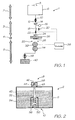
- FIG. 1 is a schematic overview of the fluidic system 1 in an inkjet printer.
- the system 1 has been divided into four sections; the ink tank 2, ink line and conditioning 3, printhead 4 and maintenance system 5. Each section is discussed in detail below.
- the ink tanks 6 store a supply of ink for the printhead.
- the tanks are usually in the form of cartridges that detachably couple to the ink conditioning section 3.
- the upstream coupling 10 and downstream coupling 12 form a connection that is free of leaks, bubbles and dust. In practice, this is difficult to achieve and some contaminants may need to be dealt with in the ink conditioning section 3.
- the flexible bag type cartridge also has drawbacks.
- the amount of ink remaining in the bag when it requires replacement can be substantial. This ink is wasted and means that the cartridge is bigger than it 'needs' to be. This is because the negative pressure can drop below a deprime threshold as the cartridge bag becomes empty.
- the deprime threshold is the pressure at which the ink is sucked back out of the nozzle chambers and back into the cartridge.
- FIG. 1 is a schematic representation of the ink cartridge 2.
- the ink tank 6 is a rigid walled container for storing the ink 42.
- the downstream coupling 12 presses on the ink outlet ball 50 to unseat it from the ink outlet 56.
- the ink outlet ball 50 pushes the actuator shaft 52 upwards against the action of the outlet spring 54.
- the actuator shaft unseats the air inlet ball 44 from the internal air inlet 48 against the bias of the return spring 58.
- ink 42 is used by the printhead, air is drawn through the external inlet 46, around the air inlet ball 44 and through the internal inlet 48.
- the air inlet valve 8 needs to be large enough to allow sufficient air inflow so as to prevent any resistance to ink flow through the fluidic system 1. However, it should also be small enough to avoid ink leakage should the printer be inverted while the cartridge is installed. Ink leakage can be largely prevented by making the air inlet smaller than the capillary length of the ink as the ink flow closed by the shut off valve 22 described below. For water based inks, the capillary is typically about 2 mm.
- the pressure regulator 14 ensures the pressure at the printhead IC 28 is less than atmospheric. A negative pressure at the printhead nozzles is necessary to prevent ink leakage. During periods of inactivity, the ink is retained in the chambers by the surface tension of the ink meniscus that forms across the nozzle. If the meniscus bulges outwardly, it can 'pin' itself to the nozzle rim to hold the ink in the chamber. However, if it contacts paper dust or other contaminants on the nozzle rim, the meniscus can be unpinned from the rim and ink will leak out of the printhead through the nozzle.
- ink cartridges are designed so that the hydrostatic pressure of the ink in the chambers is less than atmospheric pressure. This causes the meniscus at the nozzles to be concave or drawn inwards. This stops the meniscus from touching paper dust on the nozzle rim and removes the slightly positive pressure in the chamber that would drive the ink to leak out.
- the negative pressure in the chambers is limited by two factors. It can not be strong enough to deprime the chambers (i.e. suck the ink out of the chambers) and it must be less than the ejection pressure generated by the ejection drop ejection actuators. However, if the negative pressure is too weak, the nozzles can leak ink if the printhead is jolted or shaken. While this can happen during use, it is more likely to occur during the shipping and handling of printheads primed with ink.
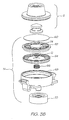
- FIG 3 shows the pressure regulator 14 and down stream coupling 12 used in the printer described in USSN 11/293,820 referenced above.
- Figure 3B is an exploded perspective for clarity.
- the pressure regulator 14 has a diaphragm 64 with a central inlet opening 72 that is biased closed by the spring 66.
- the hydrostatic pressure of the ink in the cartridge acts on the upper or upstream side of the diaphragm.
- the head of ink acting on the upstream side of the diaphragm will vary as the ink in the cartridge is consumed by the printhead.
- the ink tank 6 should have a relatively wide and flat form factor.
- the printhead IC 28 acts as a pump.
- the ejection actuators forcing ink through the nozzle array lowers the hydrostatic pressure of the ink on the downstream side of the diaphragm 64.
- the inlet 72 unseats from the central hub 74 and ink flows to the regulator outlet 70.
- the inflow through the inlet 72 immediately starts to equalize the fluid pressure on both sides of the diaphragm 64 and the force of the spring 66 again becomes enough to re-seal the inlet 72 against the central hub 74.
- the inlet 72 of the pressure regulator successively opens and shuts as the pressure difference across the diaphragm oscillates by minute amounts about the threshold pressure difference required to balance the force of the spring 66.
- the annular diaphragm support 68 need only be very shallow. The rapid opening and closing of the valve lets the pressure regulator 14 maintain a relatively constant negative hydrostatic pressure in the down stream ink flow path.
- the de-prime pressure threshold is in the range -100 mm H 2 O to -200mm H 2 O.
- the pressure regulator should be set at a pressure difference that will not exceed the de-prime threshold of the nozzles (taking into account the head of ink from the regulator to the nozzles, and bearing in mind that the head of ink above the regulator 14 varies).
- Needle valves can also be used for pressure regulation, but they are typically not configured for the ink flow rate required by the high speed pagewidth printheads developed by the Assignee.
- the diaphragm inlet 72 can easily accommodate the necessary flow rate and the rapid opening and closing of the valve during use.
- Using a diaphragm valve for the pressure regulator 14 also presents a good opportunity to incorporate a filter 60.
- the filter can be relative fine but not overly restrict the ink flow because it has a wide diameter.
- the pulse damper 16 removes spikes in the ink pressure caused by shock waves or resonant pulses through the ink line.
- the shock waves occur when the ink flowing to the printhead is stopped suddenly, such as at the end of a print job or a page.
- the Assignee's high speed, pagewidth printhead IC's need a high flow rate of supply ink during operation. Therefore, the mass of ink in the ink line from the cartridge to the nozzles is relatively large and moving at an appreciable rate. Suddenly arresting this flow gives rise to a shock wave as the ink line is a rigid structure.
- the LCP moulding 26 (see Fig. 1 ) is particularly stiff and provides almost no flex as the column of ink in the line is brought to rest.
- the shock wave can exceed the Laplace pressure (the pressure provided by the surface tension of the ink at the nozzles openings to retain ink in the nozzle chambers) and flood the front surface of the printhead IC 28. If the nozzles flood, ink may not eject and artifacts appear in the printing.
- Laplace pressure the pressure provided by the surface tension of the ink at the nozzles openings to retain ink in the nozzle chambers
- Resonant pulses in the ink occur when the nozzle firing rate matches a resonant frequency of the ink line. Again, because of the stiff structure that define the ink line, a large proportion of nozzles for one color, firing simultaneously, can create a standing wave or resonant pulse in the ink line. This can result in nozzle flooding, or conversely nozzle deprime because of the sudden pressure drop after the spike, if the Laplace pressure is exceeded.
- the present fluidic system incorporates a pulse damper 16 to remove pressure spikes from the ink line.
- the pressure spike 76 has a finite duration.
- the damped pulse 78 has a lower peak pressure but a longer duration.
- the energy dissipated in both systems (represented by areas A and B) is equal.
- the damper 16 is defined by a peristaltic pump comprising a compliant section of the ink line that can elastically flex and absorb pressure pulses.
- the pulse damper 16 is physically located near the LCP moulding 26 so that it can slowly arrest the majority of the column of ink in the ink line.
- the damper should be within about 50 mm of the LCP moulding 26.
- the nominal negative pressure at the printhead can be lower than an undamped system.
- a lower negative pressure is advantageous as there is less chance of the ink leakage from the nozzles if the printhead is knocked or jarred during installation or handling.
- the shutoff valve 22 protects against deprime and color crosstalk. It is also used during printhead purging operations.
- the valve can take many different forms as long as it fluidically isolates the printhead from the rest of the ink line. The valves role in depriming, color crosstalk and purging is discussed below.
- pagewidth printhead must be robust enough to not leak or be damaged during handling and installation. It should stay primed with ink regardless of its orientation and even modest shocks. If the ink line is open to the downstream coupling 12, pagewidth printheads deprime relatively easily. Small mechanical shocks, and even holding them vertically can provide enough hydrostatic head to overcome the Laplace threshold pressure and cause depriming.
- a shutoff valve 22 immediately upstream isolates the ink in the printhead IC 28 and the LCP moulding 26. This substantially lowers the mass and therefore the momentum of ink acting at the nozzles. This guards against leakage from jolting and jarring while the printhead is handled prior to installation.
- Color crosstalk occurs when one ink color flows into the ink line from another via the nozzles. This happens while the printhead is idle for a short time (less than an hour). If the nozzle face of the printhead IC 28 is wet from beaded ink or other fluid, there can be a fluid path between nozzles of different colors. Should the ink lines leading to the different colored nozzles have a pressure difference, the ink from the high pressure line will flow to the low pressure line until the pressure equalizes. If the crosstalk continues for several hours, the color mixing can be beyond recovery.
- Printhead IC's with high nozzle densities are very prone to color mixing unless appropriate measures are taken.
- a single dust particle on the nozzle face can anchor beads of ink from different colored nozzles and effectively become a fluid bridge between the two. Similarly, perfectly equal pressure in all the ink lines is also practically impossible.
- shutoff valves for each of the ink lines effectively arrests color mixing.
- the volume of ink in each line from the shutoff valve to the nozzles is low and a very small amount of color mixing occurs before the pressure equalizes.
- the present system uses an ink purge as part of the maintenance cycle. Purging ink clears dried ink from nozzles, and any color contaminated ink as well as other foreign particles. Ink purging is also an effective way of dealing with outgassing. Outgassing refers to the formation of bubbles in the ink line from dissolved gas (usually nitrogen) coming out of solution. Outgassing in the ink occurs when the printer stands idle for a day or so. Bubbles in the LCP molding can be particularly detrimental move to the printhead IC and prevent nozzles from firing. However, purging a relatively small volume of ink removes the bubbles. A purge involves flooding the printhead IC with ink and subsequently cleaning away the ejected ink.
- a purge volume of about 0.017 mm is sufficient (per color).
- the purging ink can be stored in a separate purge volume 18 connected to the ink line.
- the purge actuator 20 forces the ink into the line to flood the printhead IC. To do this, the ink line needs to be closed upstream of the purge actuator 20.
- a second shutoff valve (not shown) is a convenient way of achieving this.
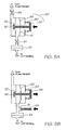
- FIGS 5A and 5B show two options for the purge mechanism.
- the purge mechanism uses two shutoff valves 82 and 84.
- the controller closes the primary shutoff valve 82 and then opens the secondary shutoff valve 84.
- a solenoid or cam (not shown) drive the purge actuator 20 which comprises the diaphragm plunger 86, plunger return spring 80 and diaphragm 88.
- the internal end of the plunger 86 has a valve stem 90 that seals against the outlet 92 of the purge reservoir 18. Depressing the plunger 86 simultaneously unseats the valve stem 90 from the outlet 92 and ejects a set volume of purge ink by compressing the purge reservoir with the diaphragm 88.
- the controller closes the primary shutoff valve 82 and opens the secondary shutoff valve 84.
- the diaphragm 88 expands the purge reservoir 18 so that it refills with fresh ink.
- both valves 82 and 84 are opened for printing or closed for transportation of the printer.
- the peristaltic purge mechanism shown in Fig. 5B has the advantage that it not need any shutoff valves which reduces the number of components in the ink line which in turn is simpler for the controller.
- the diaphragm plunger 86 is pushed to close the pressure regulator 14. Then a peristaltic plunger 94 presses on a resilient purge reservoir 18 to eject the purge ink. With the pressure regulator preventing any reverse flow, the purge ink is directed into the LCP molding and through the printhead IC. Then the pressure regulator is re-opened and the peristaltic plunger B is slowly retracted to refill the resilient purge reservoir. Following this, the system is again ready for printing. As discussed above the pressure regulator opens only when there is a sufficient pressure difference across the diaphragm 64 (see Fig. 3B ). To transport the printer, the diaphragm plunger 86 is actuated to shut the pressure regulator.
- the ink line has significant compliance in it when being transported.
- the printhead IC is least prone to any leakage if the fluidic system is completely rigid and still down stream of the shutoff valve 22, and the shutoff valve is immediately upstream of the LCP molding.
- shutoff valve 22 and a purge mechanism using a peristaltic pump.
- a section of elastically deformable ink line is compressed by a roller or cam.
- the elastic ink line is pinched shut by the roller which then moves a small distance downstream to force a small volume of ink into the printhead.
- the section of elastic ink line along which the roller moves is the purge reservoir 18 and the roller is the purge actuator 20. If the roller then remains at the downstream end of the elastic ink line, it is also an effective shutoff valve 22.
- the roller moves to the very end of the elastic section of ink line as any compliance or lack of rigidity in the ink line downstream of the shutoff valve increases the risk of deprime.
- the filter 24 should be installed as close as possible upstream of the printhead IC. Mounting the printhead IC to the filter would be ideal but impractical. Therefore, in reality, the most practical site for the filter is on the upstream face of the LCP molding 26.
- the size of the filter is a compromise between excluding particles big enough to to be trapped in the structures of the printhead IC 28, and not adding excessive flow resistance. Testing on the Assignee's printheads showed a 3 micron (pore size) filter does not adversely affecting the fluid flow and removes the vast majority of particles that can lodge in the printhead IC 28.
- the filter 24 also acts as an effective bubble trap. As discussed above, bubbles can be introduced into the ink line when the cartridge is changed or as the result of outgassing. A 3 micron filter will act as an effective bubble trap.
- the molding 26 is made from a liquid crystal polymer (LCP) which offers a number of advantages. It can be molded so that its coefficient of thermal expansion (CTE) is similar to that of silicon. It will be appreciated that any significant difference in the CTE's of the printhead IC 28 and the underlying moldings can cause the entire structure to bow. However, as the CTE of LCP in the mold direction is much less than that in the non- mold direction ( ⁇ 5ppm/°C compared to ⁇ 20ppm/°C), care must be take to ensure that the mold direction of the LCP moldings is unidirectional and aligned with the longitudinal extent of the printhead integrated circuit (IC) 28. LCP also has a relatively high stiffness with a modulus that is typically 5 times that of 'normal plastics' such as polycarbonates, styrene, nylon, PET and polypropylene.
- LCP also has a relatively high stiffness with a modulus that is typically 5 times that of 'normal plastics' such as polycarbonates, st
- the printhead IC 74 is mounted to the underside of the LCP molding 26 by a polymer sealing film (not shown).
- This film may be a thermoplastic film such as a PET or Polysulphone film, or it may be in the form of a thermoset film, such as those manufactured by AL Technologies and Rogers Corporation.
- the polymer sealing film is a laminate with adhesive layers on both sides of a central film, and laminated onto the underside of the LCP molding. A plurality of holes are laser drilled through the adhesive film to coincide with the centrally disposed ink delivery points for fluid communication between the printhead IC 28 and the channels in the LCP molding.
- the thickness of the polymer sealing film is critical to the effectiveness of the ink seal it provides.
- the polymer sealing film seals the etched channels on the non-ejection side of the printhead IC. It also seals the conduits on the LCP molding. However, as the film seals across the open end of the channels in the printhead IC, it can also bulge or sag into opening in the LCP molding. The sagging section of film runs across several of the etched channels in the printhead IC and may cause a gap that allows cross contamination of the ink colors.
- the surface is flat.
- the maintenance regime can incorporate wiping and blotting procedures. While these procedures are effective maintenance techniques, they require the printhead IC to have a robust flat surface.
- the encapsulate covering the wire bonds sits proud of the planar nozzle surface and creates a ridge along which dust and dried ink can collect.
- the printhead IC can have a redundantly wide section alongside the wire bonds so that any blotting or wiping around the nozzles is not impeded. This is a compromise solution as the larger printhead IC will lower the chip yield from each silicon wafer, thereby increasing fabrication costs.
- Printhead maintenance prevents and corrects a number of non-printing printhead states that can give rise to drying, fouling, flooding and depriming.
- the maintenance facilities in the present fluidic system includes perimeter seals, shut off valves, purges, wiping and or blotting mechanisms and keep wet dots.
- the perimeter seal retards drying when the printer is idle for long periods. It also shields the nozzle surface from dust when not in use. It should also be noted that a perimeter seal does not use ink to operate and so is not detrimental to ink usage efficiency. However, it does not keep the printhead hydrated indefinitely, particularly in hot weather. While a seal can help prevent contamination, it can not correct contamination once it occurs. Similarly, it can not correct a dried printhead or a deprimed printhead.
- shutoff valves can suppress color mixing through nozzles to ink lines at different hydrostatic pressures. They also give the printhead additional resistance to de-priming because of knocks or jolts during installation or handling. However, they can also promote de-priming as any drying of the ink will significantly reduce its volume and cause it to retreat back into the printhead IC. In light of this, shut-off valves are best used in conjunction with a perimeter seal (capper) and a re-priming mechanism.
- Purging is one mechanism for re-priming the printhead (or in other words, recovering a printhead from de-prime). It can also be used for removing particulate contaminants and recovering a dried printhead.
- ink purges necessarily waste ink, and the waste ink needs to be transported to a sump. Furthermore, ink purging can lead to ink color crosstalk. In light of this, ink purges should be used sparingly.
- Peristaltic pumps are best suited to providing the flow of purge ink as they accurately deliver a relatively precise volume to the printhead IC. Accordingly, each purge uses only as much ink as necessary and wastage is keep to a minimum.
- Purged ink will remain on the nozzle face of the printhead IC until it is cleared by a separate mechanism.
- the clearing mechanism needs to cope with a particulate burden as well the ink.
- a wide range of mechanisms have this ability, however a rotating belt mechanism has been found to be effective. However, it is relatively complex and uses a consumable film (used for the belt).
- a double roller mechanism has also been developed which can transport large volumes of ink at high rates.
- This purge ink removal mechanism is described in detail in co-pending application no. (Our Docket FNE010US) the contents of which are incorporated herein by reference.
- This mechanism has the advantage that it does not actually contact the nozzle face of the printhead IC in order to remove the purge ink, so there is no risk of nozzle damage or nozzle contamination by the roller. It also removes a particulate burden which can be disposed of with a doctor blade to prevent build up.
- Keep wet dots are also incorporated into the maintenance regime to keep the printhead IC nozzles hydrated during printing or when the printer is powered up but not currently operating. Ordinary workers will readily understand the use and implementation of keep wet dots having regard to nozzle decap times and ambient conditions. For brevity, a detailed discussion is not provided here but refer to USSN 11/097,308 for additional information.
- the coordinated operation of the individual components in the maintenance regime will require a controller.
- the controller needs to operate the associated mechanical drives and the printhead IC in the following modes:
- Waste ink is generated by purging and ejection of mixed colour ink.
- the waste ink must be actively transported to the sump as the ink can not be uncontrolled within the printer. Therefore, the ink transfer mechanism must have the capacity to collect and transfer the volumes of ink generated during 'worst case' operating conditions in terms of waste ink production.
- the collection phase is the removal of ink from the nozzle plate of the printhead IC, while the transfer phase moves the collected ink to the sump.
- Waste ink produced by purging or ejection of colour mixed ink should be rapidly removed from the printhead IC with a process that does not contaminate the nozzles. To complicate matters, there is little available adjacent the printhead. The vicinity is generally crowded with media feed mechanisms and capping structures and so on. Therefore the mechanism that collects the ink will not usually be able to accommodate the volume of waste ink produced over the life of a cartridge.
- the porous or soft roller in the dual roller design of FNE010US is capable of a high rate of ink removal while not actually contacting the printhead IC.
- the soft roller is pressed against a parallel hard roller that is partially enclosed by an absorbent body.
- Ink removed from the printhead IC adheres to the soft roller surface until it meets the nip between the rollers. There it transfers to the hard roller (polished stainless steel) and is drawn over its surface and into the absorbent material in the sump.
- the sump is necessary for controlled storage of the waste ink. However, as the sump has a finite capacity, it is necessary to decide whether the sump is to be replaceable or if it is to be sized such that its capacity exceeds the expected operational life of the printer.
- a relatively small replaceable sump may only need to be replaced a few times during the life of the printer because evaporation reduces the volume of the ink.
- the ambient operating conditions for SOHO printers can vary widely. It may be the case that the absorbent material draws additional moisture from the air.
- the sump could simply be a container. However, for better ink retention in all orientations, a foam filled structure is to be preferred. Likewise a cellulose blotter or absorbent polymer will readily draw ink away from the transfer roller.
Landscapes
- Ink Jet (AREA)
- Particle Formation And Scattering Control In Inkjet Printers (AREA)
- Power Conversion In General (AREA)
- Manipulation Of Pulses (AREA)
- Accessory Devices And Overall Control Thereof (AREA)
- Devices For Checking Fares Or Tickets At Control Points (AREA)
Claims (7)
- Imprimante à jet d'encre comprenant :- un circuit intégré (CI) de tête d'impression (28) ayant un réseau de buses pour éjecter de l'encre sur des supports d'impression ;- un élément de distribution d'encre (26) pour supporter et distribuer de l'encre au CI de tête d'impression ;- un réservoir d'alimentation en encre (6) pour stocker de l'encre ;- une conduite d'alimentation en encre définissant un trajet d'écoulement du réservoir d'alimentation en encre au CI de tête d'impression ; et,- un amortisseur d'impulsions (16) positionné le long du trajet d'écoulement, l'amortisseur d'impulsions faisant partie d'un mécanisme de pompe péristaltique ; dans laquelle, durant l'utilisation,caractérisée par le fait que :
l'amortisseur d'impulsions diminue l'amplitude des impulsions de pression dans l'encre,- l'amortisseur d'impulsions (16) est à proximité du CI de tête d'impression par rapport au réservoir d'alimentation en encre. - Imprimante à jet d'encre selon la revendication 1, dans laquelle l'amortisseur d'impulsions (16) est une section élastique de la conduite d'encre.
- Imprimante à jet d'encre selon la revendication 1, comprenant en outre une soupape (22) dans le trajet d'écoulement pour permettre ou empêcher de façon sélective un écoulement d'encre dans l'élément de distribution d'encre, l'amortisseur d'impulsions (16) étant positionné en amont de la soupape.
- Imprimante à jet d'encre selon la revendication 3, dans laquelle le mécanisme de pompe péristaltique a une longueur de conduit d'encre déformable de façon élastique et un dispositif de pincement qui peut fermer par pincement le conduit d'encre déformable de façon élastique et se déplacer jusqu'à l'étendue en aval du conduit d'encre déformable de façon élastique, de telle sorte que le conduit d'encre déformable de façon élastique est l'amortisseur d'impulsions, et le dispositif de pincement à l'étendue en aval du conduit d'encre élastique est la soupape (22) qui ferme sélectivement l'écoulement d'encre dans l'élément de distribution d'encre.
- Imprimante à jet d'encre selon la revendication 1, dans laquelle le réservoir d'alimentation en encre est une cartouche d'encre (2) ayant une soupape d'entrée d'air (8), une soupape de sortie d'encre (50) et un actionneur de soupape (52) qui ouvre la soupape d'entrée d'air en réponse à l'ouverture de la soupape de sortie d'encre.
- Imprimante à jet d'encre selon la revendication 5, comprenant en outre un régulateur de pression (14) dans la conduite d'écoulement d'encre en aval de la cartouche d'encre, dans laquelle, durant l'utilisation, le régulateur de pression est sollicité en position fermée et s'ouvre lors d'une différence de pression de seuil entre l'encre en amont et l'encre en aval.
- Imprimante à jet d'encre selon la revendication 1, dans laquelle l'élément de distribution d'encre est constitué d'un moulage LCP (polymère à cristaux liquides) (26), et dans laquelle la pompe péristaltique est positionnée dans les 50 mm du moulage LCP.
Applications Claiming Priority (6)
| Application Number | Priority Date | Filing Date | Title |
|---|---|---|---|
| AU2006901084A AU2006901084A0 (en) | 2006-03-03 | Methods and apparatus (SBF001P) | |
| AU2006901287A AU2006901287A0 (en) | 2006-03-07 | Methods and apparatus (SBF002P) | |
| AU2006201204A AU2006201204B2 (en) | 2005-10-11 | 2006-03-15 | Method of removing particulates from a printhead using a rotating roller |
| AU2006201084A AU2006201084B2 (en) | 2005-10-11 | 2006-03-15 | Printhead maintenance assembly comprising maintenance roller and cleaning mechanism |
| AU2006201083A AU2006201083B2 (en) | 2006-03-15 | 2006-03-15 | Pulse damped fluidic architecture |
| PCT/AU2006/000974 WO2007098524A1 (fr) | 2006-03-03 | 2006-07-10 | Structure fluidique à amortissement d'impulsions |
Publications (3)
| Publication Number | Publication Date |
|---|---|
| EP1991422A1 EP1991422A1 (fr) | 2008-11-19 |
| EP1991422A4 EP1991422A4 (fr) | 2010-03-10 |
| EP1991422B1 true EP1991422B1 (fr) | 2012-06-27 |
Family
ID=38458562
Family Applications (2)
| Application Number | Title | Priority Date | Filing Date |
|---|---|---|---|
| EP06760844A Not-in-force EP1991422B1 (fr) | 2006-03-03 | 2006-07-10 | Structure fluidique à amortissement d'impulsions |
| EP07701517A Not-in-force EP1991423B1 (fr) | 2006-03-03 | 2007-02-21 | Imprimante a l' architecture fluidique active |
Family Applications After (1)
| Application Number | Title | Priority Date | Filing Date |
|---|---|---|---|
| EP07701517A Not-in-force EP1991423B1 (fr) | 2006-03-03 | 2007-02-21 | Imprimante a l' architecture fluidique active |
Country Status (10)
| Country | Link |
|---|---|
| US (8) | US7771029B2 (fr) |
| EP (2) | EP1991422B1 (fr) |
| JP (2) | JP4681654B2 (fr) |
| KR (2) | KR101068705B1 (fr) |
| CN (1) | CN101287606B (fr) |
| AT (1) | ATE505332T1 (fr) |
| AU (1) | AU2007219700B2 (fr) |
| CA (1) | CA2642405C (fr) |
| DE (1) | DE602007013876D1 (fr) |
| WO (1) | WO2007098527A1 (fr) |
Cited By (1)
| Publication number | Priority date | Publication date | Assignee | Title |
|---|---|---|---|---|
| EP4714661A1 (fr) * | 2024-09-19 | 2026-03-25 | KYOCERA Document Solutions Inc. | Dispositif d'alimentation en liquide et dispositif d'impression à jet d'encre |
Families Citing this family (53)
| Publication number | Priority date | Publication date | Assignee | Title |
|---|---|---|---|---|
| US7837297B2 (en) | 2006-03-03 | 2010-11-23 | Silverbrook Research Pty Ltd | Printhead with non-priming cavities for pulse damping |
| CN101287606B (zh) | 2006-03-03 | 2010-11-03 | 西尔弗布鲁克研究有限公司 | 脉冲阻尼射流结构 |
| US7721441B2 (en) * | 2006-03-03 | 2010-05-25 | Silverbrook Research Pty Ltd | Method of fabricating a printhead integrated circuit attachment film |
| US7758177B2 (en) * | 2007-03-21 | 2010-07-20 | Silverbrook Research Pty Ltd | High flowrate filter for inkjet printhead |
| US8523143B2 (en) * | 2007-03-21 | 2013-09-03 | Zamtec Ltd | Detachable fluid coupling for inkjet printer |
| WO2009049348A1 (fr) * | 2007-10-16 | 2009-04-23 | Silverbrook Research Pty Ltd | Imprimante dotée d'une régulation de pression de la partie vide du réservoir |
| US8020980B2 (en) * | 2007-10-16 | 2011-09-20 | Silverbrook Research Pty Ltd | Printer with reservoir headspace pressure control |
| US20090179977A1 (en) * | 2008-01-16 | 2009-07-16 | Silverbrook Research Pty Ltd | Compact ink filter assembly |
| WO2009102315A1 (fr) * | 2008-02-11 | 2009-08-20 | Hewlett-Packard Development Company, L.P. | Systèmes d'alimentation en encre autonettoyants |
| US7878635B2 (en) * | 2008-03-03 | 2011-02-01 | Silverbrook Research Pty Ltd | Method of minimizing nozzle drooling during printhead priming |
| US7984640B2 (en) | 2008-08-19 | 2011-07-26 | Silverbrook Research Pty Ltd. | Pressure-based tester for a platform assembly |
| WO2010019982A1 (fr) * | 2008-08-19 | 2010-02-25 | Silverbrook Research Pty Ltd | Testeur de fuite pour un support pour circuits intégrés de tête d'impression |
| US20110164080A1 (en) * | 2008-10-14 | 2011-07-07 | Hewlett-Packard Development Company, Lp. | Fluid-jet dispensing device |
| US8025374B2 (en) | 2008-12-19 | 2011-09-27 | Silverbrook Research Pty Ltd | Ink manifold with multiple conduit shut off valve |
| WO2010068963A1 (fr) * | 2008-12-19 | 2010-06-24 | Silverbrook Research Pty Ltd | Collecteur d'encre à multiples vannes d'arrêt de conduit |
| JP5282654B2 (ja) * | 2009-05-13 | 2013-09-04 | 株式会社リコー | 画像形成装置 |
| US8702207B2 (en) | 2009-05-17 | 2014-04-22 | Hewlett-Packard Development Company, L.P. | Fluid-ejection printhead having mixing barrier |
| US8323993B2 (en) * | 2009-07-27 | 2012-12-04 | Zamtec Limited | Method of fabricating inkjet printhead assembly having backside electrical connections |
| US8388094B2 (en) * | 2009-07-31 | 2013-03-05 | Zamtec Ltd | Wide format printer with input roller and movable media engagement output |
| US8485619B2 (en) | 2010-05-17 | 2013-07-16 | Zamtec Ltd | Method of priming printhead |
| TWI534015B (zh) | 2010-05-17 | 2016-05-21 | 滿捷特科技公司 | 於印表機中降低墨水混色效應之系統 |
| US9395050B2 (en) | 2010-05-21 | 2016-07-19 | Hewlett-Packard Development Company, L.P. | Microfluidic systems and networks |
| US10132303B2 (en) | 2010-05-21 | 2018-11-20 | Hewlett-Packard Development Company, L.P. | Generating fluid flow in a fluidic network |
| US9963739B2 (en) | 2010-05-21 | 2018-05-08 | Hewlett-Packard Development Company, L.P. | Polymerase chain reaction systems |
| US9090084B2 (en) | 2010-05-21 | 2015-07-28 | Hewlett-Packard Development Company, L.P. | Fluid ejection device including recirculation system |
| JP5471892B2 (ja) * | 2010-06-29 | 2014-04-16 | ブラザー工業株式会社 | 液体吐出ヘッド及びこれを有する液体吐出装置 |
| US20120033019A1 (en) | 2010-08-09 | 2012-02-09 | Toshiba Tec Kabushiki Kaisha | Inkjet recording apparatus and inkjet recording method |
| KR101686286B1 (ko) * | 2010-10-28 | 2016-12-28 | 휴렛-팩커드 디벨롭먼트 컴퍼니, 엘.피. | 순환 펌프를 구비한 유체 분사 어셈블리 |
| JP2012179894A (ja) * | 2011-02-07 | 2012-09-20 | Sii Printek Inc | 圧力緩衝器、液体噴射ヘッド及び液体噴射装置 |
| WO2012134486A1 (fr) * | 2011-03-31 | 2012-10-04 | Hewlett-Packard Development Company, L.P. | Dispositifs fluidiques, générateurs de bulles et procédés de régulation de fluides |
| JP5821326B2 (ja) * | 2011-06-28 | 2015-11-24 | 富士ゼロックス株式会社 | 液体供給機構及び画像形成装置 |
| US8888208B2 (en) | 2012-04-27 | 2014-11-18 | R.R. Donnelley & Sons Company | System and method for removing air from an inkjet cartridge and an ink supply line |
| TWI600550B (zh) * | 2012-07-09 | 2017-10-01 | 滿捷特科技公司 | 設有具空氣柔量室之墨水輸送系統的列印機 |
| CN103625111B (zh) * | 2012-08-27 | 2016-09-28 | 研能科技股份有限公司 | 页宽喷墨打印装置 |
| ITVI20120276A1 (it) | 2012-10-19 | 2014-04-20 | New System Srl | Dispositivo di compensazione per una testa di stampa e gruppo di stampa comprendente tale dispositivo di compensazione |
| EP2783862B1 (fr) * | 2013-03-28 | 2019-05-08 | Brother Kogyo Kabushiki Kaisha | Cartouche de liquide |
| TWI626168B (zh) | 2013-07-25 | 2018-06-11 | 滿捷特科技公司 | 噴墨列印及保持噴嘴水合作用的方法 |
| EP3060402B1 (fr) * | 2013-10-22 | 2020-06-17 | Hewlett-Packard Development Company, L.P. | Régulation d'un flux d'encre vers une tête d'impression |
| US9061531B2 (en) | 2013-11-15 | 2015-06-23 | Memjet Technology Ltd. | Modular printer having narrow print zone |
| US9895888B2 (en) | 2014-04-22 | 2018-02-20 | Hewlett-Packard Development Company, L.P. | Fluid flow structure |
| CN107073963B (zh) * | 2014-10-31 | 2020-11-17 | 惠普发展公司,有限责任合伙企业 | 流体喷射装置 |
| US10052880B2 (en) | 2015-01-30 | 2018-08-21 | Hewlett-Packard Development Company, L.P. | Valves for printing fluid supply systems |
| JP6860333B2 (ja) * | 2016-01-08 | 2021-04-14 | キヤノン株式会社 | 液体吐出ヘッドおよび記録装置 |
| EP3356148B1 (fr) | 2016-02-05 | 2020-11-04 | Hewlett-Packard Development Company, L.P. | Têtes d'impression |
| TWI715755B (zh) * | 2016-05-02 | 2021-01-11 | 愛爾蘭商滿捷特科技公司 | 用於高速列印之單色噴墨列印頭 |
| US10870287B2 (en) * | 2016-05-02 | 2020-12-22 | Memjet Technology Limited | Method of inkjet printing with air-dampening of ink pressure fluctuations |
| CN207291314U (zh) | 2016-05-09 | 2018-05-01 | R.R.当纳利父子公司 | 油墨供应单元 |
| TW201838829A (zh) | 2017-02-06 | 2018-11-01 | 愛爾蘭商滿捷特科技公司 | 用於全彩頁寬列印的噴墨列印頭 |
| US10843480B2 (en) * | 2018-02-23 | 2020-11-24 | Canon Kabushiki Kaisha | Inkjet printing apparatus and control method of inkjet printing apparatus |
| WO2020162907A1 (fr) * | 2019-02-06 | 2020-08-13 | Hewlett-Packard Development Company, L.P. | Dispositif d'éjection de fluide avec un support ayant une fente |
| US11279130B2 (en) | 2019-04-29 | 2022-03-22 | Hewlett-Packard Development Company, L.P. | Fluidic dies with conductive members |
| WO2021021193A1 (fr) * | 2019-07-31 | 2021-02-04 | Hewlett-Packard Development Company, L.P. | Circulation de fluide d'impression |
| KR20240073678A (ko) | 2022-11-18 | 2024-05-27 | 삼성전자주식회사 | 유체 제어 장치 및 이를 포함하는 기판 처리 장치 |
Family Cites Families (110)
| Publication number | Priority date | Publication date | Assignee | Title |
|---|---|---|---|---|
| US766996A (en) * | 1903-06-11 | 1904-08-09 | Acme Gas Company | Safety-gage for liquids. |
| US1778439A (en) | 1924-06-26 | 1930-10-14 | Gen Electric Vapor Lamp Co | Retarded-circuit maker and breaker |
| US2030452A (en) | 1935-04-23 | 1936-02-11 | Camel Pen Company | Soluble ink fountain pen |
| JPS5732975A (en) * | 1980-08-08 | 1982-02-22 | Seiko Epson Corp | Ink jet head with pressure damper function |
| DE3041909C2 (de) | 1980-11-06 | 1983-12-01 | Argus Verwaltungsgesellschaft Mbh, 7505 Ettlingen | Schnellverschlußkupplung für Strömungsmittelleitungen |
| US4422080A (en) * | 1981-12-17 | 1983-12-20 | International Business Machines | Ink jet printing method and apparatus |
| US4512766A (en) | 1982-12-08 | 1985-04-23 | Whitman Medical Corporation | Catheter valve |
| JPS61169254A (ja) * | 1985-01-23 | 1986-07-30 | Nec Corp | ドロツプオンデマンド型インクジエツトヘツド |
| US4764449A (en) * | 1985-11-01 | 1988-08-16 | The Chromaline Corporation | Adherent sandblast photoresist laminate |
| US4730197A (en) * | 1985-11-06 | 1988-03-08 | Pitney Bowes Inc. | Impulse ink jet system |
| JPS6337955A (ja) * | 1986-08-01 | 1988-02-18 | Ricoh Co Ltd | インクジエツトプリンタの電磁弁制御回路 |
| JPH02155745A (ja) * | 1988-12-09 | 1990-06-14 | Canon Inc | 液体噴射記録装置 |
| CA2009631C (fr) * | 1989-02-17 | 1994-09-20 | Shigeo Nonoyama | Amortisseur de pression pour machine a imprimer au jet d'encre |
| DK0988871T3 (da) | 1991-12-18 | 2004-05-24 | Icu Medical Inc | Fremgangsmåde til overføring af fluid |
| JP3127581B2 (ja) * | 1992-06-26 | 2001-01-29 | セイコーエプソン株式会社 | インクジェット記録装置及び操作方法 |
| JP3158671B2 (ja) * | 1992-07-07 | 2001-04-23 | セイコーエプソン株式会社 | インクジェットヘッド及びその駆動方法 |
| EP0579399A2 (fr) * | 1992-07-09 | 1994-01-19 | Pilkington Plc | Substrat de verre pour un disque magnétique et son procédé de fabrication |
| EP0921000B1 (fr) * | 1992-10-09 | 2004-04-07 | Canon Kabushiki Kaisha | Tête d'impression par jet d'encre et imprimante l'utilisant |
| US5585826A (en) * | 1993-04-30 | 1996-12-17 | Hewlett-Packard Company | Service station for simultaneous capping/wiping of multiple inkjet cartridges having different inks |
| JP3136860B2 (ja) * | 1993-08-09 | 2001-02-19 | 富士ゼロックス株式会社 | インク供給装置 |
| JPH0789088A (ja) * | 1993-09-22 | 1995-04-04 | Fuji Xerox Co Ltd | インク供給装置 |
| JP3087535B2 (ja) * | 1993-09-29 | 2000-09-11 | 日本電気株式会社 | インクジェットカートリッジ |
| US5565900A (en) * | 1994-02-04 | 1996-10-15 | Hewlett-Packard Company | Unit print head assembly for ink-jet printing |
| JP3247558B2 (ja) * | 1994-11-07 | 2002-01-15 | キヤノンアプテックス株式会社 | プリンタ |
| US5622652A (en) * | 1995-06-07 | 1997-04-22 | Img Group Limited | Electrically-conductive liquid for directly printing an electrical circuit component onto a substrate, and a method for making such a liquid |
| JP3382432B2 (ja) * | 1995-10-11 | 2003-03-04 | キヤノン株式会社 | インクジェット記録装置 |
| US6257714B1 (en) * | 1995-10-27 | 2001-07-10 | Hewlett-Packard Company | Method and apparatus for removing air from an inkjet print cartridge |
| US5812155A (en) * | 1995-10-27 | 1998-09-22 | Hewlett-Packard Company | Apparatus for removing air from an ink-jet print cartridge |
| US5796419A (en) | 1995-12-04 | 1998-08-18 | Hewlett-Packard Company | Self-sealing fluid interconnect |
| US5776113A (en) | 1996-03-29 | 1998-07-07 | Becton Dickinson And Company | Valved PRN adapter for medical access devices |
| JPH09327924A (ja) * | 1996-06-12 | 1997-12-22 | Brother Ind Ltd | ノズルプレート |
| US6168137B1 (en) | 1996-12-30 | 2001-01-02 | Joseph R. Paradis | Swabbable check valve |
| US6063062A (en) | 1997-04-18 | 2000-05-16 | Paradis; Joseph R. | Universal luer activatable and swabbable antireflux valve |
| JPH1158736A (ja) * | 1997-08-20 | 1999-03-02 | Ricoh Co Ltd | インクジェットヘッド及びその製造方法 |
| US6033060A (en) * | 1997-08-29 | 2000-03-07 | Topaz Technologies, Inc. | Multi-channel ink supply pump |
| JPH11115212A (ja) * | 1997-10-14 | 1999-04-27 | Seiko Epson Corp | インクジェット式記録装置 |
| US6082851A (en) * | 1997-11-14 | 2000-07-04 | Canon Kabushiki Kaisha | Liquid ejection printing apparatus and liquid supply method to be employed in the same |
| JPH11170573A (ja) * | 1997-12-15 | 1999-06-29 | Fuji Xerox Co Ltd | インクジェット記録装置 |
| US5980362A (en) * | 1998-02-27 | 1999-11-09 | Interface, Inc. | Stencil for use in sandblasting stone objects |
| US6116726A (en) * | 1998-05-28 | 2000-09-12 | Hewlett-Packard Company | Ink jet printer cartridge with inertially-driven air evacuation apparatus and method |
| US6773560B2 (en) | 1998-07-10 | 2004-08-10 | Semitool, Inc. | Dry contact assemblies and plating machines with dry contact assemblies for plating microelectronic workpieces |
| ES1040834Y (es) * | 1998-08-07 | 1999-10-16 | Investronica Sistemas S A | Dispositivo del circuito de alimentacion de tinta en maquinas de dibujo raster. |
| CN1245291C (zh) * | 1998-11-14 | 2006-03-15 | 萨尔技术有限公司 | 液滴沉积装置 |
| US6228233B1 (en) | 1998-11-30 | 2001-05-08 | Applied Materials, Inc. | Inflatable compliant bladder assembly |
| JP2000203055A (ja) * | 1999-01-08 | 2000-07-25 | Pilot Corp | インクカ―トリッジ |
| JP4350187B2 (ja) | 1999-01-14 | 2009-10-21 | 株式会社キーエンス | インクジェット記録装置 |
| JP2000211156A (ja) * | 1999-01-27 | 2000-08-02 | Fuji Xerox Co Ltd | インクジェット記録装置 |
| JP3343610B2 (ja) | 1999-06-23 | 2002-11-11 | 富士ゼロックス株式会社 | インクジェット記録ヘッド及びその製造方法 |
| US6557989B1 (en) * | 1999-08-24 | 2003-05-06 | Canon Kabushiki Kaisha | Print head and ink jet printing apparatus |
| JP2001199082A (ja) * | 1999-10-08 | 2001-07-24 | Seiko Epson Corp | インクカートリッジ、インクジェット記録装置、及びインクカートリッジの装着方法 |
| ATE238910T1 (de) | 2000-01-26 | 2003-05-15 | Seiko Epson Corp | Druckkopfeinheit |
| ATE367925T1 (de) * | 2000-05-24 | 2007-08-15 | Silverbrook Res Pty Ltd | Luftzufuhranordung für einen drucker |
| US6655786B1 (en) * | 2000-10-20 | 2003-12-02 | Silverbrook Research Pty Ltd | Mounting of printhead in support member of six color inkjet modular printhead |
| EP1244558B1 (fr) * | 2000-10-23 | 2013-02-27 | Hewlett-Packard Industrial Printing Ltd. | Systeme ferme de distribution d'encre dote d'une commande de pression d'encre de la tete d'impression, et procede associe |
| JP4631158B2 (ja) * | 2000-12-07 | 2011-02-16 | ブラザー工業株式会社 | インクジェットプリンタ |
| JP2002239304A (ja) | 2001-02-21 | 2002-08-27 | Nippon Steel Corp | 海水放水路の発泡防止構造 |
| JP4075317B2 (ja) | 2001-04-11 | 2008-04-16 | 富士ゼロックス株式会社 | インクジェット記録ヘッド及びインクジェット記録装置 |
| JP4247704B2 (ja) * | 2001-09-11 | 2009-04-02 | セイコーエプソン株式会社 | 液滴吐出装置とその液体充填方法、およびデバイス製造装置とデバイス製造方法 |
| KR100438836B1 (ko) | 2001-12-18 | 2004-07-05 | 삼성전자주식회사 | 압전 방식의 잉크젯 프린트 헤드 및 그 제조방법 |
| EP1336486B1 (fr) * | 2002-02-15 | 2006-05-24 | Brother Kogyo Kabushiki Kaisha | Tête d'impression à jet d'encre |
| JP3880418B2 (ja) * | 2002-02-21 | 2007-02-14 | 日東電工株式会社 | 両面粘着シートおよびタッチパネルの表示装置への貼着固定方法 |
| JP4272381B2 (ja) | 2002-02-22 | 2009-06-03 | パナソニック株式会社 | インクジェットヘッド及び記録装置 |
| KR100471165B1 (ko) * | 2002-05-07 | 2005-03-08 | 삼성전자주식회사 | 평탄하지 않은 게이트 절연막을 구비하는 비휘발성 메모리장치 및 그 제조 방법 |
| JP3951119B2 (ja) | 2002-06-26 | 2007-08-01 | ブラザー工業株式会社 | インクジェットプリンタヘッド |
| JP3918928B2 (ja) | 2002-09-19 | 2007-05-23 | ブラザー工業株式会社 | インクジェットプリンタヘッド |
| JP4252794B2 (ja) * | 2002-11-27 | 2009-04-08 | エスアイアイ・プリンテック株式会社 | インクジェットプリンタ及びインク供給方法、並びにプリントヘッドのメンテナンス方法 |
| JP2004188636A (ja) * | 2002-12-09 | 2004-07-08 | Canon Inc | インク貯蔵部、インク、インクジェット記録装置、インクジェット記録方法 |
| US7163282B2 (en) * | 2003-06-20 | 2007-01-16 | Seiko Epson Corporation | Valve unit and liquid ejecting apparatus |
| US7087279B2 (en) * | 2003-07-17 | 2006-08-08 | 3M Innovative Properties Company | Adhesives and release liners with pyramidal structures |
| US6997053B2 (en) | 2003-08-27 | 2006-02-14 | The Boc Group, Inc. | Systems and methods for measurement of low liquid flow rates |
| US7334888B2 (en) | 2003-11-25 | 2008-02-26 | Brother Kogyo Kabushiki Kaisha | Ink cartridge |
| JP4522086B2 (ja) * | 2003-12-15 | 2010-08-11 | キヤノン株式会社 | 梁、梁の製造方法、梁を備えたインクジェット記録ヘッド、および該インクジェット記録ヘッドの製造方法 |
| US7111917B2 (en) | 2004-01-07 | 2006-09-26 | Xerox Corporation | Pressure pump system |
| US7210771B2 (en) | 2004-01-08 | 2007-05-01 | Eastman Kodak Company | Ink delivery system with print cartridge, container and reservoir apparatus and method |
| US7448734B2 (en) * | 2004-01-21 | 2008-11-11 | Silverbrook Research Pty Ltd | Inkjet printer cartridge with pagewidth printhead |
| DE602004027544D1 (de) * | 2004-01-21 | 2010-07-15 | Silver Brook Res Pty Ltd | Druckkopfanordnung und druckkopfmodul dafür |
| US7517065B2 (en) | 2004-01-23 | 2009-04-14 | Brother Kogyo Kabushiki Kaisha | Injet printhead having externally-connected terminations structured to be resistant to damage |
| US7097274B2 (en) * | 2004-01-30 | 2006-08-29 | Hewlett-Packard Development Company, L.P. | Removing gas from a printhead |
| JP2005225198A (ja) * | 2004-02-16 | 2005-08-25 | Sony Corp | 液体吐出性能維持方法及び液体吐出装置 |
| US7296879B2 (en) | 2004-02-20 | 2007-11-20 | Fujifilm Corporation | Liquid ejection head and method of producing the same |
| JP4049105B2 (ja) * | 2004-02-24 | 2008-02-20 | セイコーエプソン株式会社 | ワイピング装置および液滴吐出装置、並びに電気光学装置、電気光学装置の製造方法および電子機器 |
| US7191520B2 (en) * | 2004-03-05 | 2007-03-20 | Eastman Kodak Company | Method of optmizing inkjet printheads using a plasma-etching process |
| US7168798B2 (en) | 2004-04-26 | 2007-01-30 | Hewlett-Packard Development Company, L.P. | Hybrid ink delivery system |
| US20050250346A1 (en) * | 2004-05-06 | 2005-11-10 | Applied Materials, Inc. | Process and apparatus for post deposition treatment of low k dielectric materials |
| JP4585797B2 (ja) | 2004-06-07 | 2010-11-24 | キヤノン株式会社 | 液体供給装置 |
| JP4598828B2 (ja) * | 2004-08-09 | 2010-12-15 | シルバーブルック リサーチ ピーティワイ リミテッド | 耐光性が向上した合成に好適な水分散性ir染料 |
| JP2008513245A (ja) * | 2004-09-18 | 2008-05-01 | ザール テクノロジー リミテッド | 流体供給方法及び装置 |
| JP3952054B2 (ja) * | 2004-09-28 | 2007-08-01 | 富士フイルム株式会社 | 画像形成装置 |
| JP2006095915A (ja) * | 2004-09-30 | 2006-04-13 | Brother Ind Ltd | インクジェットヘッド、中継基板、複合基板、インクジェットヘッドの製造方法及び複合基板の製造方法 |
| JP4106048B2 (ja) * | 2004-10-25 | 2008-06-25 | 松下電器産業株式会社 | 半導体装置の製造方法及び半導体装置 |
| JP4290154B2 (ja) * | 2004-12-08 | 2009-07-01 | キヤノン株式会社 | 液体吐出記録ヘッドおよびインクジェット記録装置 |
| JP4306605B2 (ja) * | 2004-12-22 | 2009-08-05 | ブラザー工業株式会社 | インクジェットヘッドの製造方法 |
| JP4371997B2 (ja) | 2004-12-22 | 2009-11-25 | シャープ株式会社 | 表示装置用基板及びその製造方法 |
| JP4729978B2 (ja) * | 2005-01-26 | 2011-07-20 | セイコーエプソン株式会社 | 液体吐出装置の制御方法及び液体吐出装置 |
| KR100612888B1 (ko) | 2005-01-28 | 2006-08-14 | 삼성전자주식회사 | 온도 센서를 가진 압전 방식의 잉크젯 프린트헤드와잉크젯 프린트헤드에 온도 센서를 부착하는 방법 |
| KR20060092397A (ko) | 2005-02-17 | 2006-08-23 | 삼성전자주식회사 | 압전 방식의 잉크젯 프린트헤드 및 그 제조방법 |
| JP2006286788A (ja) * | 2005-03-31 | 2006-10-19 | Fujitsu Ltd | 半導体装置とその製造方法 |
| JP4506717B2 (ja) * | 2005-07-20 | 2010-07-21 | セイコーエプソン株式会社 | 液滴吐出ヘッド及び液滴吐出装置 |
| US7262134B2 (en) * | 2005-09-01 | 2007-08-28 | Micron Technology, Inc. | Microfeature workpieces and methods for forming interconnects in microfeature workpieces |
| JP2007069532A (ja) * | 2005-09-08 | 2007-03-22 | Fujifilm Corp | 液体吐出ヘッドの製造方法及び画像形成装置 |
| JP2007152621A (ja) * | 2005-12-01 | 2007-06-21 | Seiko Epson Corp | 液滴吐出ヘッド及びその製造方法 |
| JP4816070B2 (ja) * | 2005-12-27 | 2011-11-16 | ブラザー工業株式会社 | インクジェットヘッドの製造方法 |
| US7837297B2 (en) | 2006-03-03 | 2010-11-23 | Silverbrook Research Pty Ltd | Printhead with non-priming cavities for pulse damping |
| US7475976B2 (en) * | 2006-03-03 | 2009-01-13 | Silverbrook Research Pty Ltd | Printhead with elongate array of nozzles and distributed pulse dampers |
| US7721441B2 (en) * | 2006-03-03 | 2010-05-25 | Silverbrook Research Pty Ltd | Method of fabricating a printhead integrated circuit attachment film |
| CN101287606B (zh) | 2006-03-03 | 2010-11-03 | 西尔弗布鲁克研究有限公司 | 脉冲阻尼射流结构 |
| KR100723428B1 (ko) * | 2006-05-30 | 2007-05-30 | 삼성전자주식회사 | 잉크젯 프린트헤드 및 그 제조방법 |
| US7364265B1 (en) * | 2007-03-21 | 2008-04-29 | Silverbrook Research Pty Ltd | Printhead with enhanced ink supply to elongate printhead IC ends |
| US7819507B2 (en) | 2007-03-21 | 2010-10-26 | Silverbrook Research Pty Ltd | Printhead with meniscus anchor for controlled priming |
| US20080231660A1 (en) * | 2007-03-21 | 2008-09-25 | Silverbrook Research Pty Ltd | Printhead with ink conduit weir for priming control |
-
2006
- 2006-07-10 CN CN2006800379613A patent/CN101287606B/zh active Active
- 2006-07-10 JP JP2008538225A patent/JP4681654B2/ja not_active Expired - Fee Related
- 2006-07-10 KR KR1020087011150A patent/KR101068705B1/ko not_active Expired - Fee Related
- 2006-07-10 EP EP06760844A patent/EP1991422B1/fr not_active Not-in-force
-
2007
- 2007-02-21 JP JP2008556611A patent/JP2009528184A/ja active Pending
- 2007-02-21 US US11/677,049 patent/US7771029B2/en not_active Expired - Fee Related
- 2007-02-21 WO PCT/AU2007/000186 patent/WO2007098527A1/fr not_active Ceased
- 2007-02-21 US US11/677,051 patent/US7658482B2/en active Active
- 2007-02-21 CA CA2642405A patent/CA2642405C/fr active Active
- 2007-02-21 AT AT07701517T patent/ATE505332T1/de not_active IP Right Cessation
- 2007-02-21 US US11/677,050 patent/US20070206050A1/en not_active Abandoned
- 2007-02-21 AU AU2007219700A patent/AU2007219700B2/en not_active Ceased
- 2007-02-21 KR KR1020087024035A patent/KR101000208B1/ko not_active Expired - Fee Related
- 2007-02-21 EP EP07701517A patent/EP1991423B1/fr not_active Not-in-force
- 2007-02-21 DE DE602007013876T patent/DE602007013876D1/de active Active
- 2007-03-21 US US11/688,863 patent/US8025383B2/en active Active
-
2008
- 2008-11-23 US US12/276,400 patent/US7669996B2/en active Active
-
2010
- 2010-01-31 US US12/697,266 patent/US7967425B2/en active Active
- 2010-02-21 US US12/709,505 patent/US20100149294A1/en not_active Abandoned
-
2011
- 2011-05-26 US US13/117,101 patent/US20110228017A1/en not_active Abandoned
Cited By (1)
| Publication number | Priority date | Publication date | Assignee | Title |
|---|---|---|---|---|
| EP4714661A1 (fr) * | 2024-09-19 | 2026-03-25 | KYOCERA Document Solutions Inc. | Dispositif d'alimentation en liquide et dispositif d'impression à jet d'encre |
Also Published As
Similar Documents
| Publication | Publication Date | Title |
|---|---|---|
| EP1991422B1 (fr) | Structure fluidique à amortissement d'impulsions | |
| CA2619870C (fr) | Structure fluidique a amortissement d'impulsions | |
| CA2499824C (fr) | Systeme d'alimentation en liquide, structure de communication fluidique, systeme d'alimentation en encre, et tete d'impression a jet d'encre comportant cette structure de communication fluidique | |
| JP4885879B2 (ja) | 流体滴下排出 | |
| JP4532831B2 (ja) | インクジェット記録装置 | |
| US20100103234A1 (en) | Pulse damped ink supply architecture | |
| US8662634B2 (en) | Image forming apparatus including liquid ejection head for ejecting liquid droplets | |
| JP5293309B2 (ja) | 画像形成装置 | |
| AU2006201083B2 (en) | Pulse damped fluidic architecture | |
| AU2006339164B2 (en) | Pulse damped fluidic architecture | |
| JP2004122500A (ja) | 液体収納部と液体使用部とを連通する液体連通構造、および前記液体連通構造を用いた液体供給システムおよびインクジェット記録装置 | |
| JP2004050472A (ja) | インクジェット記録装置 | |
| JP5630323B2 (ja) | 画像形成装置の出荷方法 | |
| JP5622430B2 (ja) | インクジェットプリンタ | |
| JP4623255B2 (ja) | インクジェット記録装置 | |
| TWI419796B (zh) | 具有可選擇性隔離的泵的噴墨印表機 | |
| JP2002321391A (ja) | 液体用流量制御装置、液体容器、液体吐出ヘッド、記録装置、および液体の流量制御方法 |
Legal Events
| Date | Code | Title | Description |
|---|---|---|---|
| PUAI | Public reference made under article 153(3) epc to a published international application that has entered the european phase |
Free format text: ORIGINAL CODE: 0009012 |
|
| 17P | Request for examination filed |
Effective date: 20080319 |
|
| AK | Designated contracting states |
Kind code of ref document: A1 Designated state(s): AT BE BG CH CY CZ DE DK EE ES FI FR GB GR HU IE IS IT LI LT LU LV MC NL PL PT RO SE SI SK TR |
|
| A4 | Supplementary search report drawn up and despatched |
Effective date: 20100208 |
|
| 17Q | First examination report despatched |
Effective date: 20100408 |
|
| REG | Reference to a national code |
Ref country code: DE Ref legal event code: R079 Ref document number: 602006030441 Country of ref document: DE Free format text: PREVIOUS MAIN CLASS: B41J0002175000 Ipc: B41J0002140000 |
|
| RIC1 | Information provided on ipc code assigned before grant |
Ipc: B41J 2/175 20060101ALI20110802BHEP Ipc: B41J 2/17 20060101ALI20110802BHEP Ipc: B41J 2/14 20060101AFI20110802BHEP Ipc: B41J 2/155 20060101ALI20110802BHEP |
|
| GRAP | Despatch of communication of intention to grant a patent |
Free format text: ORIGINAL CODE: EPIDOSNIGR1 |
|
| GRAS | Grant fee paid |
Free format text: ORIGINAL CODE: EPIDOSNIGR3 |
|
| GRAA | (expected) grant |
Free format text: ORIGINAL CODE: 0009210 |
|
| AK | Designated contracting states |
Kind code of ref document: B1 Designated state(s): AT BE BG CH CY CZ DE DK EE ES FI FR GB GR HU IE IS IT LI LT LU LV MC NL PL PT RO SE SI SK TR |
|
| DAX | Request for extension of the european patent (deleted) | ||
| REG | Reference to a national code |
Ref country code: GB Ref legal event code: FG4D |
|
| REG | Reference to a national code |
Ref country code: CH Ref legal event code: EP |
|
| REG | Reference to a national code |
Ref country code: AT Ref legal event code: REF Ref document number: 563933 Country of ref document: AT Kind code of ref document: T Effective date: 20120715 |
|
| REG | Reference to a national code |
Ref country code: IE Ref legal event code: FG4D |
|
| REG | Reference to a national code |
Ref country code: DE Ref legal event code: R096 Ref document number: 602006030441 Country of ref document: DE Effective date: 20120823 |
|
| PG25 | Lapsed in a contracting state [announced via postgrant information from national office to epo] |
Ref country code: LT Free format text: LAPSE BECAUSE OF FAILURE TO SUBMIT A TRANSLATION OF THE DESCRIPTION OR TO PAY THE FEE WITHIN THE PRESCRIBED TIME-LIMIT Effective date: 20120627 Ref country code: FI Free format text: LAPSE BECAUSE OF FAILURE TO SUBMIT A TRANSLATION OF THE DESCRIPTION OR TO PAY THE FEE WITHIN THE PRESCRIBED TIME-LIMIT Effective date: 20120627 Ref country code: SE Free format text: LAPSE BECAUSE OF FAILURE TO SUBMIT A TRANSLATION OF THE DESCRIPTION OR TO PAY THE FEE WITHIN THE PRESCRIBED TIME-LIMIT Effective date: 20120627 |
|
| REG | Reference to a national code |
Ref country code: NL Ref legal event code: T3 |
|
| REG | Reference to a national code |
Ref country code: AT Ref legal event code: MK05 Ref document number: 563933 Country of ref document: AT Kind code of ref document: T Effective date: 20120627 |
|
| REG | Reference to a national code |
Ref country code: LT Ref legal event code: MG4D Effective date: 20120627 |
|
| PG25 | Lapsed in a contracting state [announced via postgrant information from national office to epo] |
Ref country code: SI Free format text: LAPSE BECAUSE OF FAILURE TO SUBMIT A TRANSLATION OF THE DESCRIPTION OR TO PAY THE FEE WITHIN THE PRESCRIBED TIME-LIMIT Effective date: 20120627 Ref country code: GR Free format text: LAPSE BECAUSE OF FAILURE TO SUBMIT A TRANSLATION OF THE DESCRIPTION OR TO PAY THE FEE WITHIN THE PRESCRIBED TIME-LIMIT Effective date: 20120928 Ref country code: LV Free format text: LAPSE BECAUSE OF FAILURE TO SUBMIT A TRANSLATION OF THE DESCRIPTION OR TO PAY THE FEE WITHIN THE PRESCRIBED TIME-LIMIT Effective date: 20120627 |
|
| PG25 | Lapsed in a contracting state [announced via postgrant information from national office to epo] |
Ref country code: SK Free format text: LAPSE BECAUSE OF FAILURE TO SUBMIT A TRANSLATION OF THE DESCRIPTION OR TO PAY THE FEE WITHIN THE PRESCRIBED TIME-LIMIT Effective date: 20120627 Ref country code: RO Free format text: LAPSE BECAUSE OF FAILURE TO SUBMIT A TRANSLATION OF THE DESCRIPTION OR TO PAY THE FEE WITHIN THE PRESCRIBED TIME-LIMIT Effective date: 20120627 Ref country code: IS Free format text: LAPSE BECAUSE OF FAILURE TO SUBMIT A TRANSLATION OF THE DESCRIPTION OR TO PAY THE FEE WITHIN THE PRESCRIBED TIME-LIMIT Effective date: 20121027 Ref country code: AT Free format text: LAPSE BECAUSE OF FAILURE TO SUBMIT A TRANSLATION OF THE DESCRIPTION OR TO PAY THE FEE WITHIN THE PRESCRIBED TIME-LIMIT Effective date: 20120627 Ref country code: CY Free format text: LAPSE BECAUSE OF FAILURE TO SUBMIT A TRANSLATION OF THE DESCRIPTION OR TO PAY THE FEE WITHIN THE PRESCRIBED TIME-LIMIT Effective date: 20120627 Ref country code: EE Free format text: LAPSE BECAUSE OF FAILURE TO SUBMIT A TRANSLATION OF THE DESCRIPTION OR TO PAY THE FEE WITHIN THE PRESCRIBED TIME-LIMIT Effective date: 20120627 Ref country code: BE Free format text: LAPSE BECAUSE OF FAILURE TO SUBMIT A TRANSLATION OF THE DESCRIPTION OR TO PAY THE FEE WITHIN THE PRESCRIBED TIME-LIMIT Effective date: 20120627 Ref country code: CZ Free format text: LAPSE BECAUSE OF FAILURE TO SUBMIT A TRANSLATION OF THE DESCRIPTION OR TO PAY THE FEE WITHIN THE PRESCRIBED TIME-LIMIT Effective date: 20120627 |
|
| PG25 | Lapsed in a contracting state [announced via postgrant information from national office to epo] |
Ref country code: IT Free format text: LAPSE BECAUSE OF FAILURE TO SUBMIT A TRANSLATION OF THE DESCRIPTION OR TO PAY THE FEE WITHIN THE PRESCRIBED TIME-LIMIT Effective date: 20120627 Ref country code: PL Free format text: LAPSE BECAUSE OF FAILURE TO SUBMIT A TRANSLATION OF THE DESCRIPTION OR TO PAY THE FEE WITHIN THE PRESCRIBED TIME-LIMIT Effective date: 20120627 Ref country code: PT Free format text: LAPSE BECAUSE OF FAILURE TO SUBMIT A TRANSLATION OF THE DESCRIPTION OR TO PAY THE FEE WITHIN THE PRESCRIBED TIME-LIMIT Effective date: 20121029 Ref country code: MC Free format text: LAPSE BECAUSE OF NON-PAYMENT OF DUE FEES Effective date: 20120731 |
|
| REG | Reference to a national code |
Ref country code: CH Ref legal event code: PL |
|
| PG25 | Lapsed in a contracting state [announced via postgrant information from national office to epo] |
Ref country code: DK Free format text: LAPSE BECAUSE OF FAILURE TO SUBMIT A TRANSLATION OF THE DESCRIPTION OR TO PAY THE FEE WITHIN THE PRESCRIBED TIME-LIMIT Effective date: 20120627 Ref country code: LI Free format text: LAPSE BECAUSE OF NON-PAYMENT OF DUE FEES Effective date: 20120731 Ref country code: ES Free format text: LAPSE BECAUSE OF FAILURE TO SUBMIT A TRANSLATION OF THE DESCRIPTION OR TO PAY THE FEE WITHIN THE PRESCRIBED TIME-LIMIT Effective date: 20121008 Ref country code: CH Free format text: LAPSE BECAUSE OF NON-PAYMENT OF DUE FEES Effective date: 20120731 |
|
| PLBE | No opposition filed within time limit |
Free format text: ORIGINAL CODE: 0009261 |
|
| STAA | Information on the status of an ep patent application or granted ep patent |
Free format text: STATUS: NO OPPOSITION FILED WITHIN TIME LIMIT |
|
| REG | Reference to a national code |
Ref country code: IE Ref legal event code: MM4A |
|
| 26N | No opposition filed |
Effective date: 20130328 |
|
| REG | Reference to a national code |
Ref country code: DE Ref legal event code: R097 Ref document number: 602006030441 Country of ref document: DE Effective date: 20130328 |
|
| PG25 | Lapsed in a contracting state [announced via postgrant information from national office to epo] |
Ref country code: IE Free format text: LAPSE BECAUSE OF NON-PAYMENT OF DUE FEES Effective date: 20120710 Ref country code: BG Free format text: LAPSE BECAUSE OF FAILURE TO SUBMIT A TRANSLATION OF THE DESCRIPTION OR TO PAY THE FEE WITHIN THE PRESCRIBED TIME-LIMIT Effective date: 20120927 |
|
| PG25 | Lapsed in a contracting state [announced via postgrant information from national office to epo] |
Ref country code: TR Free format text: LAPSE BECAUSE OF FAILURE TO SUBMIT A TRANSLATION OF THE DESCRIPTION OR TO PAY THE FEE WITHIN THE PRESCRIBED TIME-LIMIT Effective date: 20120627 |
|
| PG25 | Lapsed in a contracting state [announced via postgrant information from national office to epo] |
Ref country code: LU Free format text: LAPSE BECAUSE OF NON-PAYMENT OF DUE FEES Effective date: 20120710 |
|
| PG25 | Lapsed in a contracting state [announced via postgrant information from national office to epo] |
Ref country code: HU Free format text: LAPSE BECAUSE OF FAILURE TO SUBMIT A TRANSLATION OF THE DESCRIPTION OR TO PAY THE FEE WITHIN THE PRESCRIBED TIME-LIMIT Effective date: 20060710 |
|
| REG | Reference to a national code |
Ref country code: FR Ref legal event code: TP Owner name: MEMJET TECHNOLOGY LIMITED, IE Effective date: 20140923 Ref country code: FR Ref legal event code: CD Owner name: MEMJET TECHNOLOGY LIMITED, IE Effective date: 20140923 Ref country code: FR Ref legal event code: CA Effective date: 20140923 |
|
| REG | Reference to a national code |
Ref country code: DE Ref legal event code: R081 Ref document number: 602006030441 Country of ref document: DE Owner name: MEMJET TECHNOLOGY LIMITED, IE Free format text: FORMER OWNER: SILVERBROOK RESEARCH PTY. LTD., BALMAIN, NEW SOUTH WALES, AU Effective date: 20141016 |
|
| REG | Reference to a national code |
Ref country code: NL Ref legal event code: TD Effective date: 20150127 Ref country code: NL Ref legal event code: SD Effective date: 20150127 |
|
| REG | Reference to a national code |
Ref country code: GB Ref legal event code: 732E Free format text: REGISTERED BETWEEN 20150129 AND 20150204 |
|
| REG | Reference to a national code |
Ref country code: FR Ref legal event code: PLFP Year of fee payment: 10 |
|
| REG | Reference to a national code |
Ref country code: FR Ref legal event code: PLFP Year of fee payment: 11 |
|
| REG | Reference to a national code |
Ref country code: FR Ref legal event code: PLFP Year of fee payment: 12 |
|
| REG | Reference to a national code |
Ref country code: FR Ref legal event code: PLFP Year of fee payment: 13 |
|
| PGFP | Annual fee paid to national office [announced via postgrant information from national office to epo] |
Ref country code: NL Payment date: 20200726 Year of fee payment: 15 |
|
| PGFP | Annual fee paid to national office [announced via postgrant information from national office to epo] |
Ref country code: FR Payment date: 20200727 Year of fee payment: 15 |
|
| REG | Reference to a national code |
Ref country code: NL Ref legal event code: MM Effective date: 20210801 |
|
| PG25 | Lapsed in a contracting state [announced via postgrant information from national office to epo] |
Ref country code: NL Free format text: LAPSE BECAUSE OF NON-PAYMENT OF DUE FEES Effective date: 20210801 Ref country code: FR Free format text: LAPSE BECAUSE OF NON-PAYMENT OF DUE FEES Effective date: 20210731 |
|
| P01 | Opt-out of the competence of the unified patent court (upc) registered |
Effective date: 20230414 |
|
| PGFP | Annual fee paid to national office [announced via postgrant information from national office to epo] |
Ref country code: DE Payment date: 20240729 Year of fee payment: 19 |
|
| PGFP | Annual fee paid to national office [announced via postgrant information from national office to epo] |
Ref country code: GB Payment date: 20240729 Year of fee payment: 19 |
|
| REG | Reference to a national code |
Ref country code: DE Ref legal event code: R119 Ref document number: 602006030441 Country of ref document: DE |
|
| GBPC | Gb: european patent ceased through non-payment of renewal fee |
Effective date: 20250710 |
|
| PG25 | Lapsed in a contracting state [announced via postgrant information from national office to epo] |
Ref country code: GB Free format text: LAPSE BECAUSE OF NON-PAYMENT OF DUE FEES Effective date: 20250710 |
|
| PG25 | Lapsed in a contracting state [announced via postgrant information from national office to epo] |
Ref country code: DE Free format text: LAPSE BECAUSE OF NON-PAYMENT OF DUE FEES Effective date: 20260203 |