EP2001016A2 - Linsenansteuereinrichtung, optische aufnahmeeinrichtung und installationsjustier verfahren - Google Patents
Linsenansteuereinrichtung, optische aufnahmeeinrichtung und installationsjustier verfahren Download PDFInfo
- Publication number
- EP2001016A2 EP2001016A2 EP07714559A EP07714559A EP2001016A2 EP 2001016 A2 EP2001016 A2 EP 2001016A2 EP 07714559 A EP07714559 A EP 07714559A EP 07714559 A EP07714559 A EP 07714559A EP 2001016 A2 EP2001016 A2 EP 2001016A2
- Authority
- EP
- European Patent Office
- Prior art keywords
- lens
- driving device
- light beam
- collimation lens
- base
- Prior art date
- Legal status (The legal status is an assumption and is not a legal conclusion. Google has not performed a legal analysis and makes no representation as to the accuracy of the status listed.)
- Granted
Links
Images



Classifications
-
- G—PHYSICS
- G11—INFORMATION STORAGE
- G11B—INFORMATION STORAGE BASED ON RELATIVE MOVEMENT BETWEEN RECORD CARRIER AND TRANSDUCER
- G11B7/00—Recording or reproducing by optical means, e.g. recording using a thermal beam of optical radiation by modifying optical properties or the physical structure, reproducing using an optical beam at lower power by sensing optical properties; Record carriers therefor
- G11B7/12—Heads, e.g. forming of the optical beam spot or modulation of the optical beam
- G11B7/135—Means for guiding the beam from the source to the record carrier or from the record carrier to the detector
- G11B7/1392—Means for controlling the beam wavefront, e.g. for correction of aberration
- G11B7/13925—Means for controlling the beam wavefront, e.g. for correction of aberration active, e.g. controlled by electrical or mechanical means
-
- G—PHYSICS
- G11—INFORMATION STORAGE
- G11B—INFORMATION STORAGE BASED ON RELATIVE MOVEMENT BETWEEN RECORD CARRIER AND TRANSDUCER
- G11B7/00—Recording or reproducing by optical means, e.g. recording using a thermal beam of optical radiation by modifying optical properties or the physical structure, reproducing using an optical beam at lower power by sensing optical properties; Record carriers therefor
- G11B7/08—Disposition or mounting of heads or light sources relatively to record carriers
- G11B7/082—Aligning the head or the light source relative to the record carrier otherwise than during transducing, e.g. adjusting tilt set screw during assembly of head
-
- G—PHYSICS
- G11—INFORMATION STORAGE
- G11B—INFORMATION STORAGE BASED ON RELATIVE MOVEMENT BETWEEN RECORD CARRIER AND TRANSDUCER
- G11B7/00—Recording or reproducing by optical means, e.g. recording using a thermal beam of optical radiation by modifying optical properties or the physical structure, reproducing using an optical beam at lower power by sensing optical properties; Record carriers therefor
- G11B7/12—Heads, e.g. forming of the optical beam spot or modulation of the optical beam
- G11B7/135—Means for guiding the beam from the source to the record carrier or from the record carrier to the detector
- G11B7/1372—Lenses
- G11B7/1376—Collimator lenses
-
- G—PHYSICS
- G11—INFORMATION STORAGE
- G11B—INFORMATION STORAGE BASED ON RELATIVE MOVEMENT BETWEEN RECORD CARRIER AND TRANSDUCER
- G11B7/00—Recording or reproducing by optical means, e.g. recording using a thermal beam of optical radiation by modifying optical properties or the physical structure, reproducing using an optical beam at lower power by sensing optical properties; Record carriers therefor
- G11B7/12—Heads, e.g. forming of the optical beam spot or modulation of the optical beam
- G11B7/22—Apparatus or processes for the manufacture of optical heads, e.g. assembly
Definitions
- the present invention relates to lens driving devices used in optical pick up devices that record and reproduce information on/from optical media such as optical disks and relates to those optical pick up devices. It also relates to mounting and adjusting methods when the lens driving devices are mounted on the optical pick up devices.
- a transparent layer is provided on the data recording face of an optical medium to protect the face.
- a correction method may be sometimes used in a conventional optical pick up device in which a lens driving means moves a collimation lens to correct a convergence-divergence angle of a light beam entering an objective lens.
- Another correction method may also be used in which a lens driving means moves a beam expanding lens to correct a convergence-divergence angle of a light beam entering an objective lens.
- the lens driving means is in most cases configured in such a way that two guide shafts positioned in a casing of the optical pick up device are inserted into a lens moving unit so that a stepping motor positioned in the casing can control the unit movement (Patent Document 1).
- Patent Document 1 Japanese Patent Laid-Open Publication No. 2005-100481 ( Fig. 1 through 3 )
- the collimation lens movement may cause movements of a light beam spot on an optical sensor of an optical sensing system, which results in offsets of sensor signals, affecting playability of the optical pick up system.
- the present invention has been made to solve the problems described above and aims to provide a lens driving device and an optical pick up device with structures capable of downsizing.
- a lens driving device includes:
- a lens driving device is capable of being downsized.
- Embodiment 1 A lens driving device and an optical pick up device of Embodiment 1 according to the present invention will be explained below, using figures.
- the lens driving device according to Embodiment 1 has a feature in its structure with which its mounting angles can be adjusted with respect to the optical pick up device.
- Fig. 1 is a cross-sectional view of the optical pick up device on which the lens driving device of Embodiment 1 according to the present invention is mounted.
- the lens driving device includes a function to correct spherical aberration caused by differences among transparent layers, which will be described later. Each component of the optical pick up device will be explained, using Fig. 1 .
- a base 1 is provided with a semiconductor laser 2, a diffraction grating 3, a dichroic prism 4, and a polarizing prism 5.
- the semiconductor laser 2 emits light as a divergent light beam, which reaches a collimation lens 6 to be converted into a collimated light beam.
- the collimation lens 6 is fixed to a movable holder 7 which has a structure movable along a guide shaft 8 in the optical axis directions. Together with a motor-a driving source, the collimation lens 6, the movable holder 7 and the guide shaft 8 are mounted onto a mounting base 16, which is adjusted to and fixed on the base 1.
- a light beam converted to a collimated one through the collimation lens 6 is perpendicularly reflected by the reflection mirror 9, passes through a polarization plate 10, enters objective lens 11, and is focused on an optical disk.
- the objective lens 11 is placed on a lens holder 12.
- the lens holder 12 is provided with driving coils 13 and supported by a plurality of wires, which supplies electricity to the coils and suspends the lens holder.
- the amount of current flowing in the driving coils 13 is controlled to generate an acting force in a magnetic field generated by magnets 14a and 14b so that the objective lens 11 is controlled for tracking and focusing controls with respect to a data recording face of the optical disk.
- An actuator base 15 is provided with a set of electromagnetic drive components that drive the objective lens 11 in the focusing and the tracking directions, configuring an objective lens actuator, which is fixed to the base 1.
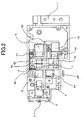
- Fig. 2 is a bottom view of the optical pick up device shown in Fig. 1 .
- an outgoing light beam from the semiconductor laser 2 passes through the diffraction grating 3, the dichroic prism 4, and the polarizing prism 5; and then, the light beam is converted to a collimated light beam by the collimation lens 6, is reflected by the reflection mirror 9, and enters the objective lens to be focused on the optical disk.
- a light beam reflected by the optical disk passes through the objective lens 11 to become a collimated light beam again and returns via the reflection mirror 9 to the collimation lens 6. Then, the light beam is converted to a convergence light beam through the collimation lens 6, turned by the polarizing prism 5, and passes through a cylindrical lens 24 to enter an optical sensor 25. Focusing and tracking control signals for the objective lens actuator and reproduction signals are obtained from the light beam sensed by the optical sensor 25.
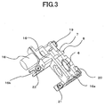
- Fig. 3 is a perspective view for explaining a configuration of the lens driving device.
- the lens driving device includes, as described above, a function as a spherical-aberration corrector to correct spherical aberration caused by the transparent layers of optical disks.
- a guide shaft 8 is cantilevered on the mounting base 16 formed by molding.
- the guide shaft is inserted into the lens holder 7 so that the lens holder 7 accurately slides in the direction along the guide shaft 8.
- the collimation lens 6 is provided in the lens holder 7, to which an anti-rotation guide shaft 16a is inserted; and, a threaded stud 19 is provided on a stepping motor 18 as a driving source to engage the holder.
- the anti-rotation guide shaft 16a is integrally-formed with the mounting base 16 and is approximately parallel to the guide shaft 8. Rotation of the threaded stud 19 transmits driving force to the lens holder 7, which can translate the lens holder 7 and the collimation lens 6.
- This lens driving device is fixed to the base 1 of the optical pick up device with a spring 20 and screws 21 and 22. Furthermore, an eccentric pin is inserted into a U-shaped adjustment notch 16b, as described later. In addition, as shown in the figures, a leaf spring is used as the spring 20.
- Fig. 4 is another perspective view of the device, viewed from the opposite side of that viewed in Fig. 3 .
- a spherical seat 16c is formed on a side of the mounting base 16, which is an opposite side of that shown in Fig. 3 .
- the spherical seat 16c is positioned in accordance with a hole or a concave portion in the base 1 of the optical pick up device, then the lens driving device is fixed to the optical pick up device with the spring 20 and the screws 21 and 22.
- the lens driving device has such a structure that a pitch angle and a roll angle can be adjusted with respect to a light beam of a light condensing system in the optical pick up device. More specifically, as shown in the figures, a weighted point by the spring 20 and the position of the screw 22 are oppositely positioned across the spherical seat 16c, and the pitch angle is adjusted by adjusting the height of the projection part of the screw 22. The roll angle is adjusted in such a way that the eccentric pin is inserted into the U-shaped adjustment notch 16b and turned to rotate the lens driving device with the spherical seat 16c being a rotation axis.
- the spherical seat 16c serves as a fulcrum section of the lens driving device with respect to the optical pick up device.
- Fig. 5 shows a reference case in which the principal point of the collimation lens 6 is positioned at the middle point along the light beam axis.
- the luminous point 201 of the semiconductor laser emits a divergent light beam 202
- the collimation lens 6 is positioned at such a position X0 that the position of the luminous point 201 coincides with the focal point of the lens.
- the collimation lens 6 converts the beam to a collimated light beam 203, which is narrowed by the objective lens 11 positioned in the collimated light beam, then passes through a transparent layer 100 of the optical disk, and is focused on the data recording face 204.
- a light beam reflected by the data recording face 204 is perpendicularly turned by a slant plane 205 which is inclined by 45 degrees and schematically expresses an optical-path turning mirror, and is focused on a four-division optical sensor 206.
- a light sensing surface of the four-division optical sensor 206 is divided into regions A, B, C, and D, as shown in the figure; and when the collimation lens is positioned at the reference position shown in Fig. 5 , the position of the sensing surface is adjusted and fixed so that the amount of light beam incident on (the region A + the region C) equals that on (the region B + the region D).
- a cylindrical lens is disposed in front of the four-division optical sensor 206. This cylindrical lens functions to generate an astigmatism amount corresponding to a defocusing amount between the objective lens 11 and the data recording face 204.
- the figure of a light collecting spot on the four-division optical sensor 206 is deformed in A-C directions or B-D directions.
- the four-division optical sensor 206 senses the defocusing amount between the objective lens 11 and the data recording face 204.
- the optical pick up device performs focusing control of the objective lens 11 by performing feedback control of an actuator, driving the objective lens 11, so as to reduce to zero a sensing signal value that is outputted from the four-division optical sensor 206 and corresponds to the light amount difference (A + C) - (B + D).
- the collimation lens 6 has been moved toward the optical disk.
- the collimation lens 6 has been moved from the reference position X0 to a position Xf being closer to the optical disk 100.
- the travel distance of the light beam through the transparent layer of the optical disk 100 is shorter than that in Fig. 5 , and the data recording face 204a is positioned closer to the collimation lens 6. Therefore, the optical pick up device moves the collimation lens 6 toward the optical disk to correct spherical aberration caused by the differences among the travel distances through the transparent layers, whereby a convergence light beam 203a enters into the objective lens 11 to be focused on the data recording face 204a.
- the focusing control of the objective lens 11 is performed with respect to the data recording face 204a of the optical disk 100 in such a way that the position of the objective lens is controlled so as to reduce to zero a sensing signal value that is outputted from the four-division optical sensor 206 and corresponds to the light amount difference (A + C) - (B + D). Therefore, when an offset of the light collecting spot is produced due to the factors as described above, it is impossible to control the objective lens 11 correctly to a focusing position.
- the optical pick up device moves the collimation lens 6 away from the optical disk to correct spherical aberration caused by the differences among the travel distances through the transparent layers, whereby a convergence light beam 203b enters into the objective lens 11 to be focused on the data recording face 204b.
- the collimation lens 6 When the collimation lens 6 is moved, as shown in Fig. 7 , with its principal point displaced from the reference line, the reflection light beam from the optical disk 100 is incident upon the reflection plane 205 at an angle. Thus, the position of the light collecting spot shifts on the four-division optical sensor 206.
- the lens driving device has a structure with which its pitch angle and roll angle can be adjusted with respect to the optical axis when the device is mounted on the optical pick up device. Therefore, even when the collimation lens 6 is moved, displacement errors with respect to the optical axis-such as those explained in Fig. 6 and Fig. 7 -are reduced to curb straightness errors.
- explanations will be made about how to mount the lens driving device on the optical pick up device and how to adjust straightness errors of the device, using figures.
- Fig. 8 is a cross-sectional view of the optical pick up device for explaining its optical system.
- the semiconductor laser 2 provided on the base 1 emits the divergence light beam 202, which is converted to the collimated light beam 203 by the collimation lens 6.
- the collimation lens 6 is mounted on the base 1 by means of the spherical seat 16c of the mounting base.
- this lens driving device When this lens driving device is mounted, the position of the collimation lens 6 has been adjusted so that the principal point thereof coincides with the spherical center of the spherical seat 16c. That is, the collimation lens 6 is positioned so that a plane perpendicular to the optical axis includes the spherical center of the spherical seat 16c and the principal point of the collimation lens 6. Therefore, a plane including the optical axis, where the principal point of the collimation lens 6 is positioned, and the spherical seat 16c is approximately perpendicular to a mounting surface of the base of the optical pick up device.
- the lens driving device can be adjusted with a pitch angle whose vertex is at the principal point of the collimation lens 6 and which changes its magnitude in directions 303 parallel to the sheet showing Fig. 8 .
- the pitch angle is adjusted by adjusting the height of the projection part of the screw 22.
- the collimated light beam 203 from the collimation lens 6 passes through a base hole 1a of the base 1 that is opened in the beam traveling direction, so that the beam can be observed.
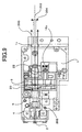
- Fig. 9 is a bottom view of the optical pick up device shown in Fig. 8 . Because the collimation lens 6 is positioned described above, the lens driving device can be adjusted with a roll angle whose vertex is at the principal point of the collimation lens 6 and which changes its magnitude in directions 304 parallel to the sheet showing Fig. 9 .
- the roll angle 304 is adjusted by turning and adjusting the eccentric pin inserted in the U-shaped adjustment notch 16b.
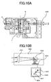
- Figs. 10 are illustrations for a method of adjusting straightness error of the collimation lens.
- the collimation lens 6 converts the beam to a collimated light beam 203, which passes the base hole 1b of the base 1 and enters an autocollimator 400.
- the autocollimator 400 monitors the incident angle of the collimated light beam 203.
- the collimated light beam 203 entering the autocollimator 400 is converged by a collimation lens 401; then, its optical path is turned by a prism 402; and the light beam is led to a two-dimensional optical sensor 403 such as a CCD.
- a two-dimensional optical sensor 403 such as a CCD.
- the incident angle of the light beam can be observed with respect to the reference position by obtaining outputs from the two-dimensional optical sensor 403.
- Procedure for adjusting straightness error of the collimation lens is as follows. Firstly, the reference position of the autocollimator 400 is adjusted to be on an optical axis joining the luminous point of the semiconductor laser 2 to the principal point of the collimation lens 6. Thereby, a light beam can be observed on the monitor 404 as an initial position 405. Secondly, the collimation lens 6 is moved forward within a movable range. This is the same movement as that performed when the lens is moved to approach the optical disk during actual reproducing and recording operations.
- the lens driving device moves the collimation lens 6 with zero straightness error, there are no displacements of the optical axis that has been initially adjusted, whereby the collimated light beam 203 from the base 1 is observed on the monitor 404 as the initial position 405 without any displacements.
- the irradiation angle of the collimated light beam 203 is varied, so that the light beam is observed on the monitor 404 of the autocollimator 400 at such a position that is displaced apart from the initial position 405 to a position 406, a position 404 or the like according to its varied direction. Similar displacements are similarly observed when the collimation lens 6 is moved backward within the movable range. That is, if the straightness error of the lens driving device is zero, the light beam is always observed in the initial position 405; and if there exist deviations in the straightness error, the light beam is displaced.
- straightness error of the lens driving device is to be corrected in such a way that the pitch angle and the roll angle of the lens driving device are adjusted, using the autocollimator 400, so that the incident angle of the collimated light beam 203 has no deviations to be observed on the monitor 404.
- the collimation lens 6 of the lens driving device is positioned so that a plane perpendicular to the optical axis includes the spherical center of the spherical seat 16c and the principal point of the collimation lens 6; then, considering the spherical center of the spherical seat 16c to be the vertices of the angles positionally fixed with respect to the base 1, the pitch angle and the roll angle are adjusted with respect to the optical axis.
- the collimation lens 6 is moved in the beam traveling direction; then, adjustments of the angles are made in the same manner, considering the spherical center of the spherical seat 16c to be the fixed vertices. Furthermore, the collimation lens 6 is moved in a direction opposite to the beam traveling direction to adjust the angles.
- a lens driving device and an optical pick up device can be configured with structures smaller than those of conventional ones and provide high precision straight-line movement of the collimation lens with a method easier than those used in conventional ones.
- the wavelength of a light beam is approximately 400 nm and objective lenses having an aperture ratio of approximately 0.85 are typically used.
- the wavelength of a light beam is approximately 650 nm and objective lenses having an aperture ratio of approximately 0.6 are frequently used.
- a transparent layer for the Blu-ray disc system has a thickness of approximately 0.1 mm, which is much thinner than that of approximately 0.6 mm to 1.2 mm for DVD systems. Consequently, application of a lens driving device according to the present embodiment to the Blu-ray disc system is very advantageous.
- a base hole 1a is opened on a casing of a base 1 that is positioned on the light beam traveling path
- the position of the base hole is not limited to that one and any position may be used as long as the light beam having passed through the collimation lens can be observed. That is, the light beam having passed through the collimation lens may be observed after it is reflected by a mirror or the like.
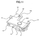
- Fig. 11 is a perspective view for explaining a lens driving device according to Embodiment 2, which view corresponds to that for Embodiment 1 shown in Fig. 4 .
- the lens driving device according to the present embodiment has a feature in that a cylindrical protrusion 500 is integrally formed with a mounting base 16.
- a base 1 of an optical pick up device has a spherical concave portion that opposes to the protrusion 500.
- the spherical center of the spherical concave portion is positioned on the central optical axis of the collimation lens.
- the cylindrical protrusion 500 is fitted onto the concave portion, which is configured in a spherical shape on the base 1, to be fixed with a spring 20 and screws 21 and 22. Since detail adjustment procedures hereinafter are the same as those in Embodiment 1, explanations will be omitted.
- the shape of the protrusion is not limited to these shapes.
- any shape may be used, for example, a prism, a cone, and a triangular pyramid.
- protrusions of the spherical seat and the cylindrical protrusion are integrally formed with the mounting base; however, they may be produced as separated parts.
- a lens driving device is mounted on an optical pick up device; however, it may be mounted on a part (attachment member) that is separated and different from the main body of the optical pick up device.
- the lens driving device may be fixed to the separated part, and then the separated part may be fixed to the optical pick up device; otherwise, the separated part may be fixed to the optical pick up device, and then the lens driving device may be fixed to the part.
- the U-shaped adjustment notch 16b has been in a slit-like shape; however, as long as the shape of the notch has two faces approximately parallel to the optical axis, any shape of the notch may be used, such as a hole in an oblong shape.
- a leaf spring has been used for the spring 20; however, a coil spring or an elastic body such as rubber, may be used as long as they are elastic.
Landscapes
- Physics & Mathematics (AREA)
- Optics & Photonics (AREA)
- Optical Head (AREA)
- Lens Barrels (AREA)
- Moving Of The Head For Recording And Reproducing By Optical Means (AREA)
Applications Claiming Priority (2)
| Application Number | Priority Date | Filing Date | Title |
|---|---|---|---|
| JP2006090561 | 2006-03-29 | ||
| PCT/JP2007/053056 WO2007122848A1 (ja) | 2006-03-29 | 2007-02-20 | レンズ駆動装置、光ピックアップ装置、及び取付調整方法 |
Publications (4)
| Publication Number | Publication Date |
|---|---|
| EP2001016A2 true EP2001016A2 (de) | 2008-12-10 |
| EP2001016A9 EP2001016A9 (de) | 2009-03-11 |
| EP2001016A4 EP2001016A4 (de) | 2009-12-30 |
| EP2001016B1 EP2001016B1 (de) | 2012-04-18 |
Family
ID=38624765
Family Applications (1)
| Application Number | Title | Priority Date | Filing Date |
|---|---|---|---|
| EP07714559A Ceased EP2001016B1 (de) | 2006-03-29 | 2007-02-20 | Linsenansteuereinrichtung, optische aufnahmeeinrichtung und justierungsverfahren |
Country Status (5)
| Country | Link |
|---|---|
| US (1) | US7679846B2 (de) |
| EP (1) | EP2001016B1 (de) |
| JP (1) | JP4329878B2 (de) |
| CN (1) | CN101401156B (de) |
| WO (1) | WO2007122848A1 (de) |
Cited By (1)
| Publication number | Priority date | Publication date | Assignee | Title |
|---|---|---|---|---|
| EP2202738A1 (de) | 2008-12-26 | 2010-06-30 | Samsung Electronics Co., Ltd. | Optische Lesekopfvorrichtung und Steuerungsverfahren dafür |
Families Citing this family (6)
| Publication number | Priority date | Publication date | Assignee | Title |
|---|---|---|---|---|
| CN101647067B (zh) * | 2007-03-19 | 2013-02-13 | 柯尼卡美能达精密光学株式会社 | 光拾取装置的制造方法及光拾取装置 |
| JP5179332B2 (ja) * | 2008-12-04 | 2013-04-10 | シャープ株式会社 | 光ピックアップ装置のレンズ位置調整機構、光ピックアップ装置、光ディスク装置、及び光ピックアップ装置のレンズ位置調整方法 |
| CN103135192A (zh) * | 2011-11-23 | 2013-06-05 | 鸿富锦精密工业(深圳)有限公司 | 镜头调整结构 |
| US11471117B2 (en) * | 2017-03-20 | 2022-10-18 | Dentsply Sirona Inc. | Multiposition collimation device and x-ray imaging systems |
| CN110460762B (zh) * | 2019-09-17 | 2024-09-24 | 迈兴(厦门)电子有限公司 | 一种模具监视器可调景深装置及其使用方法 |
| CN116088192B (zh) * | 2022-12-20 | 2025-09-16 | 昂纳科技(深圳)集团股份有限公司 | 一种光路调节装置 |
Family Cites Families (29)
| Publication number | Priority date | Publication date | Assignee | Title |
|---|---|---|---|---|
| JPS59223953A (ja) * | 1983-06-03 | 1984-12-15 | Matsushita Electric Ind Co Ltd | 光ピツクアツプ |
| JPS61150158A (ja) | 1984-12-24 | 1986-07-08 | Ricoh Co Ltd | タ−ンテ−ブル面と光ピツクアツプ光軸との垂直度調整方法 |
| JP2634852B2 (ja) * | 1988-05-07 | 1997-07-30 | シャープ株式会社 | 対物レンズ駆動装置の傾き調整機構 |
| JPH02220228A (ja) | 1989-02-21 | 1990-09-03 | Matsushita Graphic Commun Syst Inc | 光学ヘッド |
| US5223970A (en) * | 1989-03-16 | 1993-06-29 | Asahi Kogaku Kogyo Kabushiki Kaisha | Optical axis adjusting mechanism and method for optical information recording and reproducing device, and jig therefor |
| EP0473425B1 (de) * | 1990-08-29 | 1997-07-02 | Kabushiki Kaisha Toshiba | Abspielgerät für optische Platten zur optischen Verarbeitung von Information |
| US5313334A (en) * | 1991-07-29 | 1994-05-17 | Sony Corporation | Objective lens moving actuator |
| JPH07129966A (ja) | 1993-11-05 | 1995-05-19 | Matsushita Electric Ind Co Ltd | マルチビーム光ヘッド |
| US5638169A (en) * | 1994-12-21 | 1997-06-10 | Hughes Electronics | Method and apparatus for centering optical lens mount |
| JPH1070340A (ja) | 1996-08-26 | 1998-03-10 | Sankyo Seiki Mfg Co Ltd | 光走査装置 |
| JPH10326421A (ja) * | 1997-05-26 | 1998-12-08 | Sony Corp | 光学ピックアップ |
| JPH11259893A (ja) * | 1998-01-09 | 1999-09-24 | Sony Corp | 光学ヘッド、記録及び/又は再生装置並びに記録及び/又は再生方法、並びに厚み検出方法 |
| CN1118798C (zh) * | 1998-01-09 | 2003-08-20 | 索尼公司 | 光头,记录和/或复制方法,以及用来检测厚度的方法 |
| JP2000048374A (ja) * | 1998-07-30 | 2000-02-18 | Matsushita Electric Ind Co Ltd | ディスク記録再生装置 |
| JP3638465B2 (ja) * | 1999-03-15 | 2005-04-13 | 株式会社日立国際電気 | X線断層撮像装置及びそのステージ位置調整方法 |
| US6932271B2 (en) * | 2000-01-27 | 2005-08-23 | Ricoh Company, Ltd. | Optical scan module, optical scanner, optical scan method, image generator and image reader |
| JP3727826B2 (ja) * | 2000-05-08 | 2005-12-21 | アルパイン株式会社 | 光学式ピックアップ |
| JP2002175638A (ja) * | 2000-12-06 | 2002-06-21 | Matsushita Electric Ind Co Ltd | 光ピックアップの光学系調整方法 |
| US6968563B2 (en) | 2001-07-27 | 2005-11-22 | Kabushiki Kaisha Toshiba | Optical head |
| JP2003077140A (ja) | 2001-08-31 | 2003-03-14 | Sony Corp | 記録媒体駆動装置におけるガイド軸の傾き調整方法 |
| JP2003091847A (ja) | 2001-09-17 | 2003-03-28 | Sony Corp | 光学ヘッド装置の駆動方法及び装置及び光学式情報処理装置 |
| JP3759046B2 (ja) * | 2002-01-29 | 2006-03-22 | ミツミ電機株式会社 | 光学ピックアップ装置用レンズホルダ |
| JP2004039144A (ja) * | 2002-07-04 | 2004-02-05 | Sony Corp | 光学ピックアップ装置及び記録再生装置 |
| JP2005100481A (ja) | 2003-09-22 | 2005-04-14 | Hitachi Ltd | 光ディスク装置 |
| JP4353780B2 (ja) | 2003-12-05 | 2009-10-28 | 三洋電機株式会社 | 光ピックアップ装置 |
| JP2005235269A (ja) * | 2004-02-18 | 2005-09-02 | Tdk Corp | レンズ用のアクチュエータ、光ヘッド、光記録再生装置、光再生装置、多層記録媒体用光記録再生装置及び多層記録媒体用光再生装置 |
| US7450308B2 (en) * | 2004-04-27 | 2008-11-11 | Panasonic Corporation | Beam shaping lens, lens part, mounting plate, optical head, optical information recording and reproducing apparatus, computer, image recording and reproducing apparatus, image reproducing apparatus, server and car navigation system |
| JP4902110B2 (ja) | 2004-10-25 | 2012-03-21 | パナソニック株式会社 | 光ピックアップ装置 |
| US20060028935A1 (en) | 2004-08-03 | 2006-02-09 | Matsushita Electric Industrial Co., Ltd. | Optical pickup device, optical disk apparatus, and light-receiving unit |
-
2007
- 2007-02-20 CN CN2007800084880A patent/CN101401156B/zh not_active Expired - Fee Related
- 2007-02-20 JP JP2008511982A patent/JP4329878B2/ja not_active Expired - Fee Related
- 2007-02-20 WO PCT/JP2007/053056 patent/WO2007122848A1/ja not_active Ceased
- 2007-02-20 US US12/224,309 patent/US7679846B2/en not_active Expired - Fee Related
- 2007-02-20 EP EP07714559A patent/EP2001016B1/de not_active Ceased
Cited By (1)
| Publication number | Priority date | Publication date | Assignee | Title |
|---|---|---|---|---|
| EP2202738A1 (de) | 2008-12-26 | 2010-06-30 | Samsung Electronics Co., Ltd. | Optische Lesekopfvorrichtung und Steuerungsverfahren dafür |
Also Published As
| Publication number | Publication date |
|---|---|
| EP2001016A4 (de) | 2009-12-30 |
| CN101401156B (zh) | 2011-07-27 |
| JP4329878B2 (ja) | 2009-09-09 |
| WO2007122848A1 (ja) | 2007-11-01 |
| US20090135508A1 (en) | 2009-05-28 |
| US7679846B2 (en) | 2010-03-16 |
| EP2001016A9 (de) | 2009-03-11 |
| JPWO2007122848A1 (ja) | 2009-09-03 |
| CN101401156A (zh) | 2009-04-01 |
| EP2001016B1 (de) | 2012-04-18 |
Similar Documents
| Publication | Publication Date | Title |
|---|---|---|
| EP1551016B1 (de) | Optisches Abtastsystem mit Antrieb für sphärische Kompensation | |
| US7679846B2 (en) | Lens driving device, optical pick up device and adjusting method | |
| JPH0728585Y2 (ja) | ガルバノミラー装置 | |
| JP3855931B2 (ja) | 光ヘッド装置 | |
| US20080298214A1 (en) | Objective lens actuator utilizing piezoelectric elements | |
| JP3820016B2 (ja) | 光学素子の調整取付構造 | |
| EP0735528B1 (de) | Abtastvorrichtung einer optischen Platte | |
| US7573787B2 (en) | Actuator, optical device, and optical recording/reproducing apparatus | |
| JP3819987B2 (ja) | 集積型光学ユニット | |
| US7289400B2 (en) | Optical disc drive having a movable aberration correcting lens | |
| JPH0836768A (ja) | 対物レンズ駆動装置 | |
| CN100401394C (zh) | 光学拾取系统 | |
| US20050002288A1 (en) | Optical pickup device and method for controlling the same | |
| JP2694972B2 (ja) | 光ヘッド装置 | |
| JP4947940B2 (ja) | 光ピックアップ装置 | |
| KR0138138B1 (ko) | 광픽업 | |
| JPS63144423A (ja) | 光ヘツド装置 | |
| JP2767137B2 (ja) | 光学式情報記録再生装置用光学系の光軸調整機構 | |
| JPS621127A (ja) | 光ピツクアツプ装置 | |
| JPH0676304A (ja) | 光ピックアップ組付け調整装置 | |
| JPH0969231A (ja) | 光ピックアップ装置 | |
| JPH0684179A (ja) | 光記録再生装置 | |
| EP0148278A1 (de) | Lichtaufnahmekopf | |
| JPH09106550A (ja) | 光ピックアップ装置 | |
| JP2004119012A (ja) | 対物レンズ駆動装置 |
Legal Events
| Date | Code | Title | Description |
|---|---|---|---|
| PUAI | Public reference made under article 153(3) epc to a published international application that has entered the european phase |
Free format text: ORIGINAL CODE: 0009012 |
|
| 17P | Request for examination filed |
Effective date: 20080806 |
|
| AK | Designated contracting states |
Kind code of ref document: A2 Designated state(s): DE GB |
|
| PUAB | Information related to the publication of an a document modified or deleted |
Free format text: ORIGINAL CODE: 0009199EPPU |
|
| DAX | Request for extension of the european patent (deleted) | ||
| RBV | Designated contracting states (corrected) |
Designated state(s): DE GB |
|
| A4 | Supplementary search report drawn up and despatched |
Effective date: 20091126 |
|
| RIC1 | Information provided on ipc code assigned before grant |
Ipc: G11B 7/22 20060101ALI20091120BHEP Ipc: G11B 7/125 20060101ALI20091120BHEP Ipc: G11B 7/08 20060101AFI20080118BHEP Ipc: G11B 7/135 20060101ALI20091120BHEP |
|
| 17Q | First examination report despatched |
Effective date: 20100312 |
|
| RTI1 | Title (correction) |
Free format text: LENS DRIVING DEVICE, OPTICAL PICKUP DEVICE AND ADJUSTING METHOD |
|
| GRAP | Despatch of communication of intention to grant a patent |
Free format text: ORIGINAL CODE: EPIDOSNIGR1 |
|
| GRAS | Grant fee paid |
Free format text: ORIGINAL CODE: EPIDOSNIGR3 |
|
| GRAA | (expected) grant |
Free format text: ORIGINAL CODE: 0009210 |
|
| AK | Designated contracting states |
Kind code of ref document: B1 Designated state(s): DE GB |
|
| REG | Reference to a national code |
Ref country code: GB Ref legal event code: FG4D |
|
| REG | Reference to a national code |
Ref country code: DE Ref legal event code: R096 Ref document number: 602007022087 Country of ref document: DE Effective date: 20120621 |
|
| PLBE | No opposition filed within time limit |
Free format text: ORIGINAL CODE: 0009261 |
|
| STAA | Information on the status of an ep patent application or granted ep patent |
Free format text: STATUS: NO OPPOSITION FILED WITHIN TIME LIMIT |
|
| 26N | No opposition filed |
Effective date: 20130121 |
|
| REG | Reference to a national code |
Ref country code: DE Ref legal event code: R097 Ref document number: 602007022087 Country of ref document: DE Effective date: 20130121 |
|
| PGFP | Annual fee paid to national office [announced via postgrant information from national office to epo] |
Ref country code: GB Payment date: 20140219 Year of fee payment: 8 |
|
| PGFP | Annual fee paid to national office [announced via postgrant information from national office to epo] |
Ref country code: DE Payment date: 20140417 Year of fee payment: 8 |
|
| REG | Reference to a national code |
Ref country code: DE Ref legal event code: R084 Ref document number: 602007022087 Country of ref document: DE |
|
| REG | Reference to a national code |
Ref country code: GB Ref legal event code: 746 Effective date: 20141104 |
|
| REG | Reference to a national code |
Ref country code: DE Ref legal event code: R084 Ref document number: 602007022087 Country of ref document: DE Effective date: 20141107 |
|
| REG | Reference to a national code |
Ref country code: DE Ref legal event code: R119 Ref document number: 602007022087 Country of ref document: DE |
|
| GBPC | Gb: european patent ceased through non-payment of renewal fee |
Effective date: 20150220 |
|
| PG25 | Lapsed in a contracting state [announced via postgrant information from national office to epo] |
Ref country code: GB Free format text: LAPSE BECAUSE OF NON-PAYMENT OF DUE FEES Effective date: 20150220 Ref country code: DE Free format text: LAPSE BECAUSE OF NON-PAYMENT OF DUE FEES Effective date: 20150901 |