EP2003276A1 - Mécanisme de réglage pour un bras pivotant - Google Patents
Mécanisme de réglage pour un bras pivotant Download PDFInfo
- Publication number
- EP2003276A1 EP2003276A1 EP08016259A EP08016259A EP2003276A1 EP 2003276 A1 EP2003276 A1 EP 2003276A1 EP 08016259 A EP08016259 A EP 08016259A EP 08016259 A EP08016259 A EP 08016259A EP 2003276 A1 EP2003276 A1 EP 2003276A1
- Authority
- EP
- European Patent Office
- Prior art keywords
- actuating
- mechanism according
- spring
- adjusting
- actuating mechanism
- Prior art date
- Legal status (The legal status is an assumption and is not a legal conclusion. Google has not performed a legal analysis and makes no representation as to the accuracy of the status listed.)
- Granted
Links
- 230000007246 mechanism Effects 0.000 title claims abstract description 78
- 238000013519 translation Methods 0.000 claims abstract description 10
- 230000005540 biological transmission Effects 0.000 claims description 49
- 230000033001 locomotion Effects 0.000 claims description 33
- 238000013016 damping Methods 0.000 claims description 16
- 239000000725 suspension Substances 0.000 claims description 13
- 238000006073 displacement reaction Methods 0.000 claims description 5
- 239000012530 fluid Substances 0.000 claims description 2
- 230000009471 action Effects 0.000 abstract description 2
- 230000006835 compression Effects 0.000 description 8
- 238000007906 compression Methods 0.000 description 8
- 238000013461 design Methods 0.000 description 3
- 230000008859 change Effects 0.000 description 2
- 230000008878 coupling Effects 0.000 description 2
- 238000010168 coupling process Methods 0.000 description 2
- 238000005859 coupling reaction Methods 0.000 description 2
- 230000002349 favourable effect Effects 0.000 description 2
- 241000309551 Arthraxon hispidus Species 0.000 description 1
- 238000011161 development Methods 0.000 description 1
- 230000000694 effects Effects 0.000 description 1
- 238000009434 installation Methods 0.000 description 1
- 238000000034 method Methods 0.000 description 1
- 230000008569 process Effects 0.000 description 1
- 238000012549 training Methods 0.000 description 1
- 230000007704 transition Effects 0.000 description 1
Images


Classifications
-
- E—FIXED CONSTRUCTIONS
- E05—LOCKS; KEYS; WINDOW OR DOOR FITTINGS; SAFES
- E05F—DEVICES FOR MOVING WINGS INTO OPEN OR CLOSED POSITION; CHECKS FOR WINGS; WING FITTINGS NOT OTHERWISE PROVIDED FOR, CONCERNED WITH THE FUNCTIONING OF THE WING
- E05F1/00—Closers or openers for wings, not otherwise provided for in this subclass
- E05F1/08—Closers or openers for wings, not otherwise provided for in this subclass spring-actuated, e.g. for horizontally sliding wings
- E05F1/10—Closers or openers for wings, not otherwise provided for in this subclass spring-actuated, e.g. for horizontally sliding wings for swinging wings, e.g. counterbalance
- E05F1/1041—Closers or openers for wings, not otherwise provided for in this subclass spring-actuated, e.g. for horizontally sliding wings for swinging wings, e.g. counterbalance with a coil spring perpendicular to the pivot axis
- E05F1/1066—Closers or openers for wings, not otherwise provided for in this subclass spring-actuated, e.g. for horizontally sliding wings for swinging wings, e.g. counterbalance with a coil spring perpendicular to the pivot axis with a traction spring
- E05F1/1075—Closers or openers for wings, not otherwise provided for in this subclass spring-actuated, e.g. for horizontally sliding wings for swinging wings, e.g. counterbalance with a coil spring perpendicular to the pivot axis with a traction spring for counterbalancing
-
- E—FIXED CONSTRUCTIONS
- E05—LOCKS; KEYS; WINDOW OR DOOR FITTINGS; SAFES
- E05D—HINGES OR SUSPENSION DEVICES FOR DOORS, WINDOWS OR WINGS
- E05D15/00—Suspension arrangements for wings
- E05D15/40—Suspension arrangements for wings supported on arms movable in vertical planes
-
- E—FIXED CONSTRUCTIONS
- E05—LOCKS; KEYS; WINDOW OR DOOR FITTINGS; SAFES
- E05F—DEVICES FOR MOVING WINGS INTO OPEN OR CLOSED POSITION; CHECKS FOR WINGS; WING FITTINGS NOT OTHERWISE PROVIDED FOR, CONCERNED WITH THE FUNCTIONING OF THE WING
- E05F1/00—Closers or openers for wings, not otherwise provided for in this subclass
- E05F1/08—Closers or openers for wings, not otherwise provided for in this subclass spring-actuated, e.g. for horizontally sliding wings
- E05F1/10—Closers or openers for wings, not otherwise provided for in this subclass spring-actuated, e.g. for horizontally sliding wings for swinging wings, e.g. counterbalance
-
- E—FIXED CONSTRUCTIONS
- E05—LOCKS; KEYS; WINDOW OR DOOR FITTINGS; SAFES
- E05F—DEVICES FOR MOVING WINGS INTO OPEN OR CLOSED POSITION; CHECKS FOR WINGS; WING FITTINGS NOT OTHERWISE PROVIDED FOR, CONCERNED WITH THE FUNCTIONING OF THE WING
- E05F5/00—Braking devices, e.g. checks; Stops; Buffers
- E05F5/02—Braking devices, e.g. checks; Stops; Buffers specially for preventing the slamming of swinging wings during final closing movement, e.g. jamb stops
-
- E—FIXED CONSTRUCTIONS
- E05—LOCKS; KEYS; WINDOW OR DOOR FITTINGS; SAFES
- E05D—HINGES OR SUSPENSION DEVICES FOR DOORS, WINDOWS OR WINGS
- E05D15/00—Suspension arrangements for wings
- E05D15/26—Suspension arrangements for wings for folding wings
- E05D15/262—Suspension arrangements for wings for folding wings folding vertically
-
- E—FIXED CONSTRUCTIONS
- E05—LOCKS; KEYS; WINDOW OR DOOR FITTINGS; SAFES
- E05D—HINGES OR SUSPENSION DEVICES FOR DOORS, WINDOWS OR WINGS
- E05D15/00—Suspension arrangements for wings
- E05D15/40—Suspension arrangements for wings supported on arms movable in vertical planes
- E05D15/403—Suspension arrangements for wings supported on arms movable in vertical planes with arms fixed on the wing pivoting about an axis outside the wing
-
- E—FIXED CONSTRUCTIONS
- E05—LOCKS; KEYS; WINDOW OR DOOR FITTINGS; SAFES
- E05D—HINGES OR SUSPENSION DEVICES FOR DOORS, WINDOWS OR WINGS
- E05D3/00—Hinges with pins
- E05D3/06—Hinges with pins with two or more pins
- E05D3/14—Hinges with pins with two or more pins with four parallel pins and two arms
-
- E—FIXED CONSTRUCTIONS
- E05—LOCKS; KEYS; WINDOW OR DOOR FITTINGS; SAFES
- E05F—DEVICES FOR MOVING WINGS INTO OPEN OR CLOSED POSITION; CHECKS FOR WINGS; WING FITTINGS NOT OTHERWISE PROVIDED FOR, CONCERNED WITH THE FUNCTIONING OF THE WING
- E05F1/00—Closers or openers for wings, not otherwise provided for in this subclass
- E05F1/08—Closers or openers for wings, not otherwise provided for in this subclass spring-actuated, e.g. for horizontally sliding wings
- E05F1/10—Closers or openers for wings, not otherwise provided for in this subclass spring-actuated, e.g. for horizontally sliding wings for swinging wings, e.g. counterbalance
- E05F1/1091—Closers or openers for wings, not otherwise provided for in this subclass spring-actuated, e.g. for horizontally sliding wings for swinging wings, e.g. counterbalance with a gas spring
-
- E—FIXED CONSTRUCTIONS
- E05—LOCKS; KEYS; WINDOW OR DOOR FITTINGS; SAFES
- E05Y—INDEXING SCHEME ASSOCIATED WITH SUBCLASSES E05D AND E05F, RELATING TO CONSTRUCTION ELEMENTS, ELECTRIC CONTROL, POWER SUPPLY, POWER SIGNAL OR TRANSMISSION, USER INTERFACES, MOUNTING OR COUPLING, DETAILS, ACCESSORIES, AUXILIARY OPERATIONS NOT OTHERWISE PROVIDED FOR, APPLICATION THEREOF
- E05Y2201/00—Constructional elements; Accessories therefor
- E05Y2201/20—Brakes; Disengaging means; Holders; Stops; Valves; Accessories therefor
- E05Y2201/21—Brakes
-
- E—FIXED CONSTRUCTIONS
- E05—LOCKS; KEYS; WINDOW OR DOOR FITTINGS; SAFES
- E05Y—INDEXING SCHEME ASSOCIATED WITH SUBCLASSES E05D AND E05F, RELATING TO CONSTRUCTION ELEMENTS, ELECTRIC CONTROL, POWER SUPPLY, POWER SIGNAL OR TRANSMISSION, USER INTERFACES, MOUNTING OR COUPLING, DETAILS, ACCESSORIES, AUXILIARY OPERATIONS NOT OTHERWISE PROVIDED FOR, APPLICATION THEREOF
- E05Y2201/00—Constructional elements; Accessories therefor
- E05Y2201/20—Brakes; Disengaging means; Holders; Stops; Valves; Accessories therefor
- E05Y2201/252—Type of friction
- E05Y2201/254—Fluid or viscous friction
-
- E—FIXED CONSTRUCTIONS
- E05—LOCKS; KEYS; WINDOW OR DOOR FITTINGS; SAFES
- E05Y—INDEXING SCHEME ASSOCIATED WITH SUBCLASSES E05D AND E05F, RELATING TO CONSTRUCTION ELEMENTS, ELECTRIC CONTROL, POWER SUPPLY, POWER SIGNAL OR TRANSMISSION, USER INTERFACES, MOUNTING OR COUPLING, DETAILS, ACCESSORIES, AUXILIARY OPERATIONS NOT OTHERWISE PROVIDED FOR, APPLICATION THEREOF
- E05Y2201/00—Constructional elements; Accessories therefor
- E05Y2201/20—Brakes; Disengaging means; Holders; Stops; Valves; Accessories therefor
- E05Y2201/262—Type of motion, e.g. braking
- E05Y2201/264—Type of motion, e.g. braking linear
-
- E—FIXED CONSTRUCTIONS
- E05—LOCKS; KEYS; WINDOW OR DOOR FITTINGS; SAFES
- E05Y—INDEXING SCHEME ASSOCIATED WITH SUBCLASSES E05D AND E05F, RELATING TO CONSTRUCTION ELEMENTS, ELECTRIC CONTROL, POWER SUPPLY, POWER SIGNAL OR TRANSMISSION, USER INTERFACES, MOUNTING OR COUPLING, DETAILS, ACCESSORIES, AUXILIARY OPERATIONS NOT OTHERWISE PROVIDED FOR, APPLICATION THEREOF
- E05Y2201/00—Constructional elements; Accessories therefor
- E05Y2201/40—Motors; Magnets; Springs; Weights; Accessories therefor
- E05Y2201/47—Springs
- E05Y2201/488—Traction springs
-
- E—FIXED CONSTRUCTIONS
- E05—LOCKS; KEYS; WINDOW OR DOOR FITTINGS; SAFES
- E05Y—INDEXING SCHEME ASSOCIATED WITH SUBCLASSES E05D AND E05F, RELATING TO CONSTRUCTION ELEMENTS, ELECTRIC CONTROL, POWER SUPPLY, POWER SIGNAL OR TRANSMISSION, USER INTERFACES, MOUNTING OR COUPLING, DETAILS, ACCESSORIES, AUXILIARY OPERATIONS NOT OTHERWISE PROVIDED FOR, APPLICATION THEREOF
- E05Y2201/00—Constructional elements; Accessories therefor
- E05Y2201/60—Suspension or transmission members; Accessories therefor
- E05Y2201/606—Accessories therefor
- E05Y2201/618—Transmission ratio variation
-
- E—FIXED CONSTRUCTIONS
- E05—LOCKS; KEYS; WINDOW OR DOOR FITTINGS; SAFES
- E05Y—INDEXING SCHEME ASSOCIATED WITH SUBCLASSES E05D AND E05F, RELATING TO CONSTRUCTION ELEMENTS, ELECTRIC CONTROL, POWER SUPPLY, POWER SIGNAL OR TRANSMISSION, USER INTERFACES, MOUNTING OR COUPLING, DETAILS, ACCESSORIES, AUXILIARY OPERATIONS NOT OTHERWISE PROVIDED FOR, APPLICATION THEREOF
- E05Y2201/00—Constructional elements; Accessories therefor
- E05Y2201/60—Suspension or transmission members; Accessories therefor
- E05Y2201/622—Suspension or transmission members elements
- E05Y2201/638—Cams; Ramps
-
- E—FIXED CONSTRUCTIONS
- E05—LOCKS; KEYS; WINDOW OR DOOR FITTINGS; SAFES
- E05Y—INDEXING SCHEME ASSOCIATED WITH SUBCLASSES E05D AND E05F, RELATING TO CONSTRUCTION ELEMENTS, ELECTRIC CONTROL, POWER SUPPLY, POWER SIGNAL OR TRANSMISSION, USER INTERFACES, MOUNTING OR COUPLING, DETAILS, ACCESSORIES, AUXILIARY OPERATIONS NOT OTHERWISE PROVIDED FOR, APPLICATION THEREOF
- E05Y2800/00—Details, accessories and auxiliary operations not otherwise provided for
- E05Y2800/20—Combinations of elements
- E05Y2800/21—Combinations of elements of identical elements, e.g. of identical compression springs
-
- E—FIXED CONSTRUCTIONS
- E05—LOCKS; KEYS; WINDOW OR DOOR FITTINGS; SAFES
- E05Y—INDEXING SCHEME ASSOCIATED WITH SUBCLASSES E05D AND E05F, RELATING TO CONSTRUCTION ELEMENTS, ELECTRIC CONTROL, POWER SUPPLY, POWER SIGNAL OR TRANSMISSION, USER INTERFACES, MOUNTING OR COUPLING, DETAILS, ACCESSORIES, AUXILIARY OPERATIONS NOT OTHERWISE PROVIDED FOR, APPLICATION THEREOF
- E05Y2800/00—Details, accessories and auxiliary operations not otherwise provided for
- E05Y2800/20—Combinations of elements
- E05Y2800/242—Combinations of elements arranged in parallel relationship
-
- E—FIXED CONSTRUCTIONS
- E05—LOCKS; KEYS; WINDOW OR DOOR FITTINGS; SAFES
- E05Y—INDEXING SCHEME ASSOCIATED WITH SUBCLASSES E05D AND E05F, RELATING TO CONSTRUCTION ELEMENTS, ELECTRIC CONTROL, POWER SUPPLY, POWER SIGNAL OR TRANSMISSION, USER INTERFACES, MOUNTING OR COUPLING, DETAILS, ACCESSORIES, AUXILIARY OPERATIONS NOT OTHERWISE PROVIDED FOR, APPLICATION THEREOF
- E05Y2800/00—Details, accessories and auxiliary operations not otherwise provided for
- E05Y2800/26—Form or shape
- E05Y2800/31—Form or shape eccentric
-
- E—FIXED CONSTRUCTIONS
- E05—LOCKS; KEYS; WINDOW OR DOOR FITTINGS; SAFES
- E05Y—INDEXING SCHEME ASSOCIATED WITH SUBCLASSES E05D AND E05F, RELATING TO CONSTRUCTION ELEMENTS, ELECTRIC CONTROL, POWER SUPPLY, POWER SIGNAL OR TRANSMISSION, USER INTERFACES, MOUNTING OR COUPLING, DETAILS, ACCESSORIES, AUXILIARY OPERATIONS NOT OTHERWISE PROVIDED FOR, APPLICATION THEREOF
- E05Y2900/00—Application of doors, windows, wings or fittings thereof
- E05Y2900/20—Application of doors, windows, wings or fittings thereof for furniture, e.g. cabinets
Definitions
- the present invention relates to an actuating mechanism for a pivotally mounted actuating arm, in particular for driving a flap of a piece of furniture, with a spring device with a spring-loaded setting part and a transmission mechanism which converts the movement of the adjusting part into a pivoting movement of the actuating arm.
- Such adjusting mechanisms are known in many embodiments according to the prior art and are preferably used to move flaps or lifting doors of furniture, which are mounted on a horizontal pivot axis, from the closed position to an open position or in the reverse direction and the flap in a certain position.
- a flap holder is for example from the DE 26 53 106 become known, which has two actuating arms, which are acted upon by a spring device. Two cam sections designed differently on an actuating arm run on a contact surface on the second actuating arm.
- a technical development shows the US 5,904,411 showing a flap holder with a pivoting flap, wherein a spring-loaded actuating part is coupled via a rigid connecting arm directly to a pivotable actuating arm.
- German patent application DE 101 45 856 shows a folding lid for a cabinet, wherein a spring-loaded actuator runs on a control contour of a cam, which in turn is coupled to an actuating arm for moving the furniture flap.
- Object of the present invention is therefore to avoid the above-mentioned disadvantage of the prior art.
- the transmission mechanism has at least one adjusting device for varying the transmission ratio between the movement of the actuating part and the pivotal movement of the actuating arm.
- the gear ratio is preferably defined as the ratio of foundedsmaschinem Stellteilweg to rotation angle of the actuating arm.
- the DE 101 45 856 For example, due to the curved shape of the control contour on the closing or opening path variable transmission ratio, but this is already fixed by the control contour.
- the present invention in contrast, has a separately arranged adjustment device which allows a precise and controlled adjustment of the transmission ratio.
- the transmission ratio is variable so that one and the same actuating mechanism can be provided for advantageously moving or damping differently sized furniture flaps.
- the translation mechanism has a pivotally mounted intermediate lever, which is acted upon on the one hand by the spring-loaded actuating part and on the other hand on a trained on the actuating arm or attached control contour - preferably via a pressure roller - is applied.
- the pivotally mounted intermediate lever By the pivotally mounted intermediate lever, the leverage ratios and thus the transmission ratio of the control part can be changed to the actuating arm, preferably a continuous adjustment is provided. It may be expedient if the position of the point of application of the spring-loaded actuating part on the intermediate lever is adjustable, resulting in changed leverage. In this context, it may also be advantageous that the distance of the point of application of the spring-loaded actuating part from the axis of rotation of the intermediate lever is adjustable.
- the configuration may be such that the spring device comprises at least two or more - preferably arranged in parallel - tension springs.
- the spring device comprises at least two or more - preferably arranged in parallel - compression springs.
- spring devices are also included which comprise at least one tension spring and at least one compression spring.
- the spring device may be articulated to allow pivoting thereof to compensate for stress. As a result, the biasing forces in the direction of the actuating part can advantageously be varied or adjusted.
- a gas pressure accumulator can be used advantageously.
- a displacement device is arranged or formed on the intermediate lever, by means of which the point of application of the actuating part is adjustable.
- the biasing force of the spring device can be changed to the effect that the position of the individual pivot points to each other changed. Due to the resulting lever ratios, the adjusting mechanism can be adapted to different sizes or weights of the movable furniture flaps.
- the design may favorably be such that the displacement device comprises a rod or a threaded spindle, along which the point of application of the actuating part is displaceably mounted.
- a further advantageous embodiment of the invention results from the fact that the intermediate lever has a slotted guide, along which the spring-loaded control member is feasible.
- a curve shape preferably a spring-device-facing side, may also be provided in the slide guide, by means of which the bias of the spring device or its characteristic range can be varied.
- the transmission mechanism has at least two adjusting devices for changing the transmission ratio between the movement of the actuating part and the pivoting movement of the actuating arm. It may be expedient if two separate adjusting devices for coarse or fine adjustment of the transmission ratio are arranged.
- the arrangement according to the invention is characterized by a movable furniture part, in particular a furniture flap, with an adjusting mechanism according to the invention.
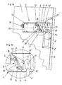
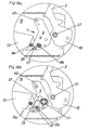
- Fig. 1a shows a schematically illustrated embodiment of an actuating mechanism 1 according to the invention in the closed position with a pivotable about a horizontal axis flap 3, 1b shows shows an enlarged view of the detail B from 1a ,
- This adjusting mechanism 1 is fastened via a suspension device 15 to a vertical inner wall of a furniture carcass 4.
- the actuating mechanism 1 has a pivotably mounted actuating arm 2, which is provided with the articulated levers 2 ', 2 "for moving the flap 3 between an open position and a closed position
- the spring device 5 acts on a displaceably mounted actuating part 13 with a force pointing in the direction of the flap 3.
- the actuating part 13 is therefore displaced linearly in accordance with the loading of the spring device 5.
- a translation mechanism 7 sets the Linear movement of the adjusting member 13 in a pivoting movement, which in turn acts on the actuating arm 2 for moving the flap 3.
- the translation mechanism 7 comprises an adjusting device 8 for varying the transmission ratio between the linear movement of the actuating member 13 and the pivotal movement of Stel Larmes 2.
- the transmission mechanism 7 has a mounted about the axis of rotation 14 intermediate lever 9, which is acted upon on the one hand by the spring-loaded actuating part 13, and on the other hand to one, formed on the actuating arm 2 or attached control contour 12 rests on a pressure roller 11.
- the adjusting contour 12 is formed or arranged at the end of the actuating arm 2 in the form of a curved control cam 10.
- the control cam 10 is mounted on the axis of rotation 17 and meshes with moving the flap 3 with the pressure roller 11.
- the intermediate lever 9 is pivoted by the spring-loaded actuator 13 in a clockwise direction about the axis of rotation 14, as will be clarified in the following figures.
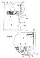
- Fig. 2a shows the adjusting mechanism 1 from Fig. 1a, 1b in a half-open position
- Fig. 2b shows an enlarged view of the detail A from Fig. 2a
- the adjusting mechanism 1 comprises a spring device 5, which is designed as a compression spring package.
- the spring device 5 is in the illustration shown in comparison to the spring device off Fig. 1 already partially relieved.
- the control cam 10 mounted on the pivot point 17 rolls on the pressure roller 11, whereby the intermediate lever 9 mounted on the pivot point 14 is moved by the spring-loaded actuating part 13 in FIG Turned clockwise.
- the contact pressure of the pressure roller 11 on the control contour 12 is determined on the one hand by the clamping force of the spring device 5 and the relative position of the control cam 10 and the control contour 12 to the pressure roller 11.
- Fig. 3a shows the adjusting mechanism 1 from Fig. 1a, 1b respectively.
- Fig. 2a, 2b in the open position
- Fig. 3b shows an enlarged view of the detail C from Fig. 3a
- the compression springs of the spring device 5 are substantially in a relaxed state, but always the intermediate lever 9 is acted upon by a certain force, so that the furniture flap 3 can be held over at least part of the pivoting in any position.
- the transmission ratio was not changed by the adjusting device 8, since the point of application 6 within the slotted guide 18 has not been displaced.
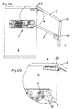
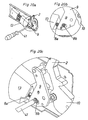
- Fig. 4a and Fig. 4b schematically show a further embodiment of the invention in a side and in a perspective view.
- the spring device 5 is in contrast to that of the Fig. 1 to 3 designed as a tension spring package.
- the spring-loaded actuating part 13 is displaceably mounted along the guide rod 51 in the figure shown.
- the spring-loaded actuator 13 acts on a trough-shaped push rod 54 which is coupled at its other end to the intermediate lever 9. Relevant is that the push rod 54 is not connected to the spring suspension 55, ie that the trough-shaped push rod 54 is slidably guided behind the spring suspension 55.
- the intermediate lever 9 is pivotally mounted on its axis of rotation 14, wherein the spring device 5 via the push rod 54, the intermediate lever 9 is acted upon by a counterclockwise force.
- the actuator arm 2 (and thus a flap 3, not shown) is in the illustrated figure in the open position.
- the actuator arm 2 is pivotally mounted on the axis of rotation 17 and has a control cam 10 with a control contour 12.
- the pressure roller 11 is pressed by the force of the spring device 5 to the control contour 12.
- the adjusting contour 12 rolls on the pressure roller 11, so that the intermediate lever 9 is pivoted about the rotation axis 14 in the clockwise direction.
- the adjustment device 8 for setting the transmission ratio comprises a rod 19 mounted on the intermediate rod 19 and a threaded spindle, along which the point of application 6 of the push rod 54 is slidably mounted.
- Fig. 5a and Fig. 5b show the adjusting mechanism 1 from Fig. 4a, 4b In a half-open position of the actuating arm 2. It can be seen that the mounted on the axis of rotation 14 intermediate lever 9 has been pivoted by the closing movement of the actuating arm in a clockwise direction. As a result of this movement, the trough-shaped push rod 54 with the spring-loaded actuating part 13 articulated thereon has also been moved further to the left. The springs of the spring device 5 are gradually tensioned in this process, the resulting force presses the pressure roller 11 against the control contour 12 of the actuating arm 2. This force can be adjusted by the adjustability of the transmission ratio so that the weight of the flap 3 is compensated, so that the flap 3 is held in preferably each pivot position of the actuating arm 2.
- Fig. 6a and Fig. 6b show the adjusting mechanism 1 from Fig. 4a, 4b respectively.
- Fig. 5a, 5b in the full closed position of the actuating arm 2 (and thus a flap 3, not shown).
- the intermediate lever 9 mounted on the axis of rotation 14 was pivoted even further clockwise.
- the now not apparent tub-shaped push rod 54 was pushed past behind the stationary mounted spring suspension 55, so that the spring-loaded actuator 13 is in the extreme end position relative to the guide rod 51 so that the springs of the spring device 5 are in a maximum tensioned state.
- the ratio was not changed by the adjustment 8 for reasons of clarity, since the point 6 has not been moved in its relative position to the rod 19.
- Fig. 7a and Fig. 7b show the adjusting mechanism 1 from the Fig. 4a, 4b to Fig. 6a, 6b in the illustrated figure, the gear ratio has been changed by an adjustment of the point 6 on the intermediate lever 9, which is achieved by the adjusting device 8 on the intermediate lever 9.
- the point of application 6 is displaceably mounted on a rod 19, wherein the rod 19 is preferably designed as a threaded spindle.
- a gear 25 - preferably a gear - provided, which can be adjusted with a hexagon 26.
- the gear 25 meshes with an intermediate 27, which is rotatably connected to the threaded spindle 19.
- the point 6 is moved by a pin 28, not shown, within the coupling piece 20, wherein the bolt 28 is provided with an internal thread.
- a rotation of the hexagon 26 thus causes a rotation of the gear 25, which moves the idle with the threaded spindle 19 mounted intermediate gear 27, wherein the rotation of the threaded spindle causes a height adjustment of a provided with an internal screw pin 28.
- the adjustment of the hexagon 26 can also be done without tools, for example with a hand-operated knurled screw.
- the point 6 can also be guided displaceably within a slotted guide 18.
- the slotted guide 18 may also have a curve shape or a curvature, whereby the bias of the spring device 5 and thus their characteristic range can be changed. Due to the changed position of the point of attack 6 other leverage ratios are created, since the position of the individual pivot points is changed to each other. In the figure shown, the pressure of the pressure roller 11 is reduced to the control contour 12 by the shifted position of the point 6, so that lighter furniture flaps 3 can be moved favorably and can be damped according to their weights.
- FIG. 8a-8d respectively. 8a'-8d ' show various applications of the adjusting mechanisms according to the invention 1.
- the drawings each show a side view of the furniture carcasses 4, where an upwardly opening furniture flap 3 is arranged.
- the top row according to the Fig. 8a-8d each show the closed position of the furniture flap 3, while the lower views according to the 8a'-8d ' in 8a ' a fold up, in 8b ' a folding folder, in Fig. 8c ' a high lift flap and in 8d ' show a Hochschwenkklappe in an open position.
- Fig. 9a and Fig. 10a show exploded views of the adjusting mechanisms Fig. 1 to 3 (Compression spring package) or the adjusting mechanism 1 off 4 to 6 (Zugfedernvers)
- Fig. 9b and Fig. 10b show the respective actuating mechanism 1 in the mounted state.
- the adjusting mechanisms 1 are mounted on a suspension device 15 on the furniture body 4.
- the threaded spindle 19 is performed by a joint head 29 and rotatably connected to an intermediate gear 27.
- the bolt 28, which has an internal thread and 20 is received within the coupling piece.
- the threaded spindle 19 engages in the thread of the bolt 28, whereby a displacement of the actuating member 13 takes place in the axial direction of the threaded spindle 19.
- a fitting 21 is provided to connect the two levers 2, 2 'with the flap 3.
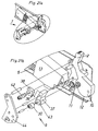
- Fig. 11a shows a side view of an exemplary Hochfaltklappe with an actuating mechanism 1 according to the invention in the closed position
- Fig. 11b shows the enlarged detail C from Fig. 11a
- the adjusting mechanism 1 is attached via a suspension device 15 to a vertical side wall of the furniture body 4.
- a furniture flap 3 is arranged at a hinge point 22.
- the furniture flap 3 is pivotally connected via a horizontal pivot axis 24 with the flap part 3 '.
- a hinge 23 is provided with at least two hinge stop parts, which allows a pivoting movement about a horizontal axis.
- the design can be made so that the actuating arm 2 is acted upon by at least a part of the pivoting path with a torque which allows a lingering of the flap 3, 3 'in any position between the open and closed positions.
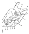
- Fig. 14a and Fig. 14b show the side view of the adjusting mechanism 1 according to another embodiment of the invention.
- the actuator arm 2 is located in Fig. 14a in a slightly open position as well as in Fig. 14b in a further open position.
- the adjusting mechanism 1 is connected via a suspension device 15 to a vertical Sidewall of a furniture body attached.
- the spring device 5 is rotatably mounted on a stationary pivot axis 16.
- This spring device 5 comprises a compression spring packet which acts on the setting part 13 with a force in the direction of the setting contour 12 of the control cam 10.
- the actuator 13 leads in contrast to the in Fig. 1 to 13 shown linear motion from a pivoting movement.
- the translation mechanism 7 comprises in the figure shown two levers 33, 33 ', which are rotatably and fixedly mounted at a respective pivot point 34, 34'. Between the two levers 33, 33 'is a user-adjustable transmission element 32 is arranged, determines the position of the ratio of Stellteilweg to angle of rotation of the actuating arm 2. If the transmission element 32 between these two levers 33, 33 'further down, so the actuator 13 can move further to the right. Thus, the expansion path and thus the range of action of the spring assembly 5 is increased.
- the lever 33 ' has at its end remote from the pivot point 34' a pressure roller 11 which is pressed against the control contour 12 of the control cam 10.
- the control cam 10 is rotatably and fixedly mounted at its pivot point 17.
- the control cam 10 is arranged or formed at the end of the actuating arm 2, by means of which a flap 3 is movable into the open or closed position.
- Figs. 15a and 15b show the embodiment Fig. 14a respectively.
- Fig. 14b By adjusting the transmission element 32 in the direction of the pivot point 34 of the lever 33, the adjusting member 13 can be moved further to the right, which has an increased expansion path of the spring device 5 and an increase in the transmission ratio result.
- the transmission ratio can be adjusted in a simple manner - depending on the position of the transmission element 32.
- the lever 33 ' has at least one slot 36 in which the transmission element 32 can be guided. The fixation takes place with the aid of the clamping screw 35.
- the attachment of the transmission element 32 can just as well be effected on the lever 33 connected to the actuating part 13.
- Fig. 16 shows an exploded view of the embodiment of the invention from the Fig. 17a, b respectively.
- Fig. 15a B. Evident are the two levers 33, 33 ', whose fixed pivot points 34, 34' are arranged offset in relation to the suspension device 15.
- the lever 33 ' has a slot 36 on, with a clamping screw 35, the lever 33 'and the transmission element 32 passes through and causes the same jamming.
- the length of the slot 36 determines the upper and lower end of the gear ratio.
- Fig. 17a shows a further embodiment of the invention
- Fig. 17b and 17c each show enlarged detailed representations.
- the acted upon by the spring device 5 with force actuator 13 is coupled via an intermediate lever 9 and the control cam 10 with the actuator arm 2.
- the transmission mechanism 7 has at least two adjusting devices 8a and 8b for varying the transmission ratio between the movement of the setting part 13 and the pivotal movement of the actuating arm 2, as well as in FIG Fig. 17b or 17c is shown.
- the bearing point position of the adjusting member 13 is adjustable on the intermediate lever 9, whereby the transmission ratio can be set exactly.
- the intermediate lever 9 is fixed and pivotally mounted at the pivot point 40.
- the transmission ratio can be changed differently by the at least two adjusting devices 8a and 8b.
- the design can be made such that the adjustment device 8a is provided for a coarse adjustment, or the adjustment device 8b for a fine adjustment of the transmission ratio.
- the adjusting devices 8a and 8b the bearing point position of the adjusting member 13 can be set exactly on the intermediate lever 9 and thus the transmission ratio.
- Fig. 17c shows an enlarged detail view Fig. 17b in the transition region between the actuating part 13 and the intermediate lever 9.
- the intended for the coarse adjustment adjustment 8a comprises a connected to the intermediate lever 9 rack 37, on which by a user (not shown) adjustable element 38 engages with at least one locking tooth 39.
- the fine adjustment 8b comprises an eccentric 30, wherein it is advantageously provided that the adjustment range of the eccentric 30 corresponds to the tooth width of the toothed rack 37, so that a gap-free adjustment range of the bearing point position of the setting part 13 on the intermediate lever 9 is made possible.
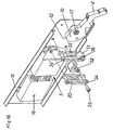
- Fig. 18a shows a side view of the attached to the hanger 15 translation mechanism 7 from Fig. 17a or 17b.
- Fig. 18b shows the same translation mechanism 7 without cover, so that the internal parts can be seen.
- the spring-loaded actuator 13 is adjustably mounted on the intermediate lever 9.
- the intermediate lever 9 is pivotally mounted at a pivot point 40.
- the actuator arm 2 is in the fully open position, so that the control cam 10 can be disengaged from the pressure roller 11.
- the locking tooth 39 belonging to the adjusting device 8a engages in the rack 37 arranged or formed on the intermediate lever 9.
- the adjusting device 8a is provided for a coarse adjustment of the transmission ratio.
- the adjusting device 8b also acts on the rack 37, wherein an eccentric 30 changes the bearing point position of the adjusting part 13 on the intermediate lever 9.
- the adjusting device 8b is provided for a fine adjustment of the transmission ratio.
- Fig. 19a shows the coarse adjustment of the transmission ratio by means of a screwdriver 41
- Fig. 19b an enlarged detail Fig. 19a
- the adjusting device 8a is actuated with the screwdriver 41.
- the force must be adjustable to control contour 12 of the control cam 10.
- Figures 20A shows the fine adjustment of the transmission ratio by means of a screwdriver 41, Fig. 8b and Fig.8c in each case enlarged detail views.
- the screwdriver 41 is attached to the adjusting device 8b.
- This fine adjustment of the transmission ratio via the previously described eccentric 30.
- the adjustment of the eccentric 30 preferably corresponds to the tooth width of the teeth of the rack 37. The combination of coarse and fine adjustment a continuous power adjustment is possible.
- Fig. 21a shows an exploded view of the two-stage adjustable translation mechanism 7 from the Fig. 17 to 20 .
- Fig. 21b shows an enlarged detail.
- the loaded by the spring device 5 actuating member 13 is slidably coupled via the bolt 42 (adjusting device 8a) and with the eccentric 30 (adjusting 8b) to the rack 37.
- the bolt 42 protrudes through the adjustable element 38, on which at least one locking tooth 39 is arranged.
- the eccentric 30 protrudes in the mounted state through the opening 43 of the rack 37.
- the front end of the intermediate lever 9 forms a cover plate 44th
- Fig. 22 shows a further embodiment of the invention in a side view.
- the actuating part 13 is connected to the actuating arm 2 via at least two levers 31, 31 'connected to one another in an articulated manner.
- known adjusting devices 8a, 8b are used for coarse or fine adjustment of the transmission ratio.
- the adjusting part 13 can be displaced by the adjusting devices 8a, 8b along the surface 49.
- a damping device 47 may be provided.
- the damping device 47 has a stop 46 which cooperates when closing the flap 3 with a arranged on the actuating arm 2 or nose 45 formed. Through the nose 45, a piston rod connected to the stop 46 is displaced into the interior of the damping device 47.
- a fluid cylinder is provided in this case, but in principle all other known according to the prior art damping devices 47 (for example, rotary damper) can be used.
- Fig. 23 shows a perspective view of the embodiment Fig. 22 ,
- Actuation of the adjusting device 8a, 8b leads to a change in position of the setting part 13 on the surface 49 of the lever 31st
- the nose 45 presses against the stop 46 of the damper 47, the last closing path of the flap 3 being damped.
- Fig. 24a and Fig. 24b show the embodiment of the Fig. 21 respectively.
- Fig. 22 in side views, wherein the actuating arm 2 in Fig. 24a in full open position and in Fig. 24b in a half open position.
- a trough 50 is provided on both levers 31', 31". In the trough 50, the pivot joint of the rotation axis 17 of the actuating arm 2 can at least partially accommodate.
- the present invention is not limited to the examples shown, but includes any variants or technical equivalents which may fall within the scope of the following claims.
- the position information selected in the description such as top, bottom, side, etc. related to the usual installation position of the actuating mechanism 1 and on the immediately described and illustrated figure and are to be transferred to a new position analogously to the new situation.
- the adjusting mechanism 1 was realized in the illustrated drawings as a lever solution. But it is just as conceivable and possible to use a gear variant. It may also be favorable to arrange the adjusting mechanism 1 according to the invention on both sides of a cabinet-shaped piece of furniture. In the figures shown, a translational movement or a pivoting movement of the spring-loaded actuating part 13 has been shown.
- a rotational movement of the actuating member 13 for example by a torsion spring
- a pivoting movement of the actuating arm 2 wherein by the adjusting device 8, an exact and defined adjustment of the transmission ratio is provided.
- the invention provides, the adjusting mechanism 1 according to the invention absolutely identical, i. E. even without mirror-image components, or to use the same on both side walls (left / right) of a piece of furniture with completely identical training.
Landscapes
- Engineering & Computer Science (AREA)
- Mechanical Engineering (AREA)
- Closing And Opening Devices For Wings, And Checks For Wings (AREA)
- Vehicle Body Suspensions (AREA)
- Power-Operated Mechanisms For Wings (AREA)
- Spinning Or Twisting Of Yarns (AREA)
- Body Structure For Vehicles (AREA)
- Supports Or Holders For Household Use (AREA)
- Load-Engaging Elements For Cranes (AREA)
- Mechanical Control Devices (AREA)
Priority Applications (1)
| Application Number | Priority Date | Filing Date | Title |
|---|---|---|---|
| SI200531119T SI2003276T1 (sl) | 2004-07-14 | 2005-04-27 | Nastavni mehanizem za nihajno uležajeno nastavnoročico |
Applications Claiming Priority (3)
| Application Number | Priority Date | Filing Date | Title |
|---|---|---|---|
| AT11902004 | 2004-07-14 | ||
| AT18592004 | 2004-11-08 | ||
| EP05734880.7A EP1766173B1 (fr) | 2004-07-14 | 2005-04-27 | Meuble avec mecanisme d'actionnement et bras pivotant reglable |
Related Parent Applications (3)
| Application Number | Title | Priority Date | Filing Date |
|---|---|---|---|
| EP05734880.7A Division EP1766173B1 (fr) | 2004-07-14 | 2005-04-27 | Meuble avec mecanisme d'actionnement et bras pivotant reglable |
| EP05734880.7A Division-Into EP1766173B1 (fr) | 2004-07-14 | 2005-04-27 | Meuble avec mecanisme d'actionnement et bras pivotant reglable |
| EP05734880.7 Division | 2005-04-27 |
Publications (2)
| Publication Number | Publication Date |
|---|---|
| EP2003276A1 true EP2003276A1 (fr) | 2008-12-17 |
| EP2003276B1 EP2003276B1 (fr) | 2010-07-14 |
Family
ID=34966336
Family Applications (2)
| Application Number | Title | Priority Date | Filing Date |
|---|---|---|---|
| EP05734880.7A Expired - Lifetime EP1766173B1 (fr) | 2004-07-14 | 2005-04-27 | Meuble avec mecanisme d'actionnement et bras pivotant reglable |
| EP08016259A Expired - Lifetime EP2003276B1 (fr) | 2004-07-14 | 2005-04-27 | Mécanisme de réglage pour un bras pivotant |
Family Applications Before (1)
| Application Number | Title | Priority Date | Filing Date |
|---|---|---|---|
| EP05734880.7A Expired - Lifetime EP1766173B1 (fr) | 2004-07-14 | 2005-04-27 | Meuble avec mecanisme d'actionnement et bras pivotant reglable |
Country Status (12)
| Country | Link |
|---|---|
| US (2) | US7500287B2 (fr) |
| EP (2) | EP1766173B1 (fr) |
| JP (2) | JP4787252B2 (fr) |
| KR (1) | KR101225356B1 (fr) |
| CN (1) | CN1985064B (fr) |
| AT (1) | ATE474118T1 (fr) |
| BR (1) | BRPI0513268B1 (fr) |
| DE (2) | DE202005021541U1 (fr) |
| ES (1) | ES2647606T3 (fr) |
| HU (1) | HUE037072T2 (fr) |
| SI (1) | SI2003276T1 (fr) |
| WO (1) | WO2006005086A1 (fr) |
Cited By (3)
| Publication number | Priority date | Publication date | Assignee | Title |
|---|---|---|---|---|
| WO2015135007A1 (fr) * | 2014-03-14 | 2015-09-17 | Julius Blum Gmbh | Mécanisme de commande pour ouvrants de meuble |
| WO2016077851A1 (fr) * | 2014-11-21 | 2016-05-26 | Julius Blum Gmbh | Mécanisme de commande pour parties mobiles de meuble |
| WO2018071930A1 (fr) * | 2016-10-17 | 2018-04-26 | Julius Blum Gmbh | Dispositif d'entraînement pour meuble |
Families Citing this family (112)
| Publication number | Priority date | Publication date | Assignee | Title |
|---|---|---|---|---|
| AT502944A1 (de) * | 2005-03-21 | 2007-06-15 | Blum Gmbh Julius | Möbel mit einem möbelkorpus und wenigstens einer hochbewegbaren klappe |
| CA2617409C (fr) * | 2005-09-20 | 2013-10-22 | Sca Hygiene Products Ab | Distributeur |
| DE102006007702B4 (de) * | 2006-02-13 | 2009-04-23 | Hetal-Werke Franz Hettich Gmbh & Co. Kg | Beschlagvorrichtung für eine Möbelklappe |
| DE202007005957U1 (de) * | 2007-02-19 | 2008-06-26 | Liebherr-Hausgeräte Ochsenhausen GmbH | Kühl- und/oder Gefriergerät |
| DE202007004621U1 (de) * | 2007-03-29 | 2008-08-07 | Hettich-Oni Gmbh & Co. Kg | Mehrgelenkscharnier |
| AT505126B1 (de) * | 2007-05-07 | 2009-05-15 | Blum Gmbh Julius | Klappenantriebssystem |
| AT505209B1 (de) * | 2007-05-07 | 2012-04-15 | Blum Gmbh Julius | Antrieb für ein bewegbares möbelteil |
| AT505879A1 (de) * | 2007-09-28 | 2009-04-15 | Blum Gmbh Julius | Stellmechanismus fur einen schwenkbar gelagerten stellarm |
| AT506196B1 (de) * | 2007-12-19 | 2010-10-15 | Blum Gmbh Julius | Stellmechanismus zum bewegen einer hochbewegbaren klappe eines möbels |
| DE102008005463A1 (de) * | 2008-01-21 | 2009-07-23 | Huwil-Werke Gmbh Möbelschloss- Und Beschlagfabriken | Halteelement zum Verstellen eines Deckels eines Möbels |
| AT506519B1 (de) * | 2008-03-06 | 2012-10-15 | Blum Gmbh Julius | Stellantrieb für eine möbelklappe mit einer montagesicherung für den leeren stellarm |
| AT506644A1 (de) * | 2008-03-21 | 2009-10-15 | Blum Gmbh Julius | Möbelantrieb zum antreiben eines bewegbaren möbelteils |
| AT507139A1 (de) * | 2008-07-18 | 2010-02-15 | Blum Gmbh Julius | Möbelantrieb |
| AT507279A1 (de) * | 2008-08-29 | 2010-03-15 | Blum Gmbh Julius | Antriebsvorrichtung für eine möbelklappe |
| US20100127606A1 (en) * | 2008-11-25 | 2010-05-27 | Mansfield Assemblies Co. | Slow open slow close appliance hinge assembly |
| KR100970472B1 (ko) * | 2008-12-12 | 2010-07-16 | 주식회사 다이아벨 | 스윙 힌지모듈 |
| EP2402536A4 (fr) * | 2009-02-27 | 2014-03-12 | Sugatsune Kogyo | Compas pour l'ouverture et la fermeture d'un battant |
| US20100251521A1 (en) * | 2009-04-01 | 2010-10-07 | Electrolux Home Products, Inc. | Door hinge assembly |
| JP5643295B2 (ja) * | 2009-05-13 | 2014-12-17 | ユリウス ブルム ゲー エム ベー ハー | フラップ扉駆動システム |
| AT508229B1 (de) * | 2009-05-13 | 2015-12-15 | Blum Gmbh Julius | Möbelklappenantrieb für verschiedene klappentypen |
| AT508529A1 (de) * | 2009-07-28 | 2011-02-15 | Blum Gmbh Julius | Stellantrieb für ein bewegbares möbelteil |
| AT508698B1 (de) | 2009-08-20 | 2017-07-15 | Blum Gmbh Julius | Möbel mit stellarmanordnung |
| CN102472353B (zh) * | 2009-08-21 | 2013-08-28 | 世嘉智尼工业株式会社 | 缓冲器位置调节装置 |
| EP2309086B1 (fr) * | 2009-10-07 | 2013-12-11 | Heinrich J. Kesseböhmer KG | Elément de retenue pour le réglage d'un couvercle de meuble |
| DE202009013347U1 (de) | 2009-10-14 | 2011-02-17 | Hettich-Heinze Gmbh & Co. Kg | Selbsteinzugs- und Dämpfungsvorrichtung |
| WO2011129154A1 (fr) * | 2010-04-16 | 2011-10-20 | スガツネ工業株式会社 | Appareil d'ouverture/de fermeture de porte |
| AT509934B1 (de) | 2010-05-20 | 2016-01-15 | Blum Gmbh Julius | Antriebsvorrichtung zum bewegen eines bewegbaren möbelteils |
| JP5944095B2 (ja) * | 2010-07-26 | 2016-07-05 | 三菱製鋼株式会社 | 開閉装置 |
| AT510984B1 (de) | 2011-02-22 | 2012-08-15 | Blum Gmbh Julius | Stellantrieb zum bewegen einer möbelklappe |
| DE102011002117A1 (de) * | 2011-04-15 | 2012-10-18 | Horst Lautenschläger | Möbelscharnier |
| AT511546B1 (de) | 2011-05-19 | 2018-10-15 | Blum Gmbh Julius | Möbelantrieb für eine bewegbare möbelklappe |
| EP2717003B1 (fr) * | 2011-05-23 | 2018-10-03 | Hefei Midea Refrigerator Co., Ltd. | Structure de fermeture de porte pour porte de réfrigérateur pivotante et réfrigérateur à porte à deux battants comprenant cette structure |
| WO2012159259A1 (fr) * | 2011-05-23 | 2012-11-29 | 合肥美的荣事达电冰箱有限公司 | Structure de fermeture de porte pour porte pivotante d'une armoire et réfrigérateur à porte à deux battants doté de cette structure de fermeture |
| ITGO20110006A1 (it) * | 2011-10-20 | 2013-04-21 | N E M Nord Est Meccanica S N C | Sistema di apertura a rinvio angolare per banchi e vetrine |
| ES2724779T3 (es) * | 2012-01-30 | 2019-09-16 | Blum Gmbh Julius | Servoaccionamiento para una tapa abatible de un mueble |
| US8572808B2 (en) | 2012-02-23 | 2013-11-05 | Sub-Zero, Inc. | Controlled closure system for a hinge |
| JP6011611B2 (ja) * | 2012-03-14 | 2016-10-19 | アイシン精機株式会社 | 開閉体の開閉補助装置 |
| WO2013153639A1 (fr) * | 2012-04-11 | 2013-10-17 | 日東工器株式会社 | Dispositif pour retenir une porte en position ouverte et dispositif de charnière de porte équipé de celui-ci |
| AT512156B1 (de) * | 2012-05-25 | 2013-06-15 | Blum Gmbh Julius | Anordnung zum Bewegen eines bewegbaren Möbelteils |
| TW201404996A (zh) * | 2012-07-27 | 2014-02-01 | Hon Hai Prec Ind Co Ltd | 鉸鏈結構 |
| CN104583518B (zh) * | 2012-09-25 | 2016-10-26 | 世嘉智尼工业株式会社 | 门扇开闭装置 |
| JP6307437B2 (ja) * | 2012-11-14 | 2018-04-04 | アダマンド並木精密宝石株式会社 | チュービングポンプ |
| DE102013101040A1 (de) * | 2013-02-01 | 2014-08-07 | Hettich-Oni Gmbh & Co. Kg | Mehrgelenkscharnier mit Dämpfung |
| AT513387B1 (de) | 2013-02-08 | 2014-04-15 | Blum Gmbh Julius | Stellantrieb zum Bewegen eines bewegbaren Möbelteiles |
| US20160047160A1 (en) * | 2013-02-27 | 2016-02-18 | Nam Duc HUYNH | Enclosure access apparatus and method |
| AT514050A1 (de) * | 2013-03-04 | 2014-09-15 | Blum Gmbh Julius | Stellantrieb für eine Möbelklappe |
| US20140260735A1 (en) * | 2013-03-15 | 2014-09-18 | Jonathan Roberts | Counterbalance system for assisting a user |
| CN103195859B (zh) * | 2013-04-22 | 2015-05-20 | 成都鑫焊众达自动化控制有限公司 | 局部旋转恒扭矩弹簧平衡装置及其实现方法 |
| AT514585B1 (de) | 2013-08-30 | 2015-02-15 | Blum Gmbh Julius | Stellantrieb für bewegbare Möbelteile |
| AT515493A1 (de) * | 2014-03-13 | 2015-09-15 | Blum Gmbh Julius | Stellantrieb für Möbelklappen |
| AT515216B1 (de) * | 2014-05-02 | 2015-07-15 | Blum Gmbh Julius | Stellantrieb für Möbelklappen |
| DE102014113970B4 (de) * | 2014-09-26 | 2016-08-18 | Samet Kalip Ve Maden Esya San. Ve Tic. A.S. | Möbelscharnier |
| DE102014113967B4 (de) * | 2014-09-26 | 2016-09-01 | Samet Kalip Ve Maden Esya San. Ve Tic. A.S. | Möbelscharnier und Möbel |
| CN104453531B (zh) * | 2014-11-10 | 2016-03-16 | 老肯医疗科技股份有限公司 | 用于医用全自动清洗机的门体组件及医用全自动清洗机 |
| US10023364B2 (en) * | 2015-01-22 | 2018-07-17 | Kantec Co., Ltd. | Hinge structure |
| SI3259425T1 (sl) * | 2015-02-17 | 2020-08-31 | Arturo Salice S.P.A. | Dvižni sistem za krila pohištva |
| DE102015102393A1 (de) * | 2015-02-19 | 2016-08-25 | Hettich Holding Gmbh & Co. Ohg | Schwenkbeschlag |
| SG11201706840WA (en) | 2015-03-31 | 2017-09-28 | Vhsquared Ltd | Peptide construct having a protease-cleavable linker |
| WO2016156468A1 (fr) | 2015-03-31 | 2016-10-06 | Vhsquared Limited | Polypeptides |
| CN104775701B (zh) * | 2015-04-02 | 2017-03-01 | 伍志勇 | 用于家具上翻门的锁离调节机构 |
| CN104790794B (zh) * | 2015-04-16 | 2016-08-24 | 伍志勇 | 用于家具上翻门的启闭力调节机构 |
| BR112017021309A2 (pt) * | 2015-04-30 | 2018-06-26 | Salice Arturo Spa | dobradiça para folhas de mobiliário que oscilam em torno de pelo menos um eixo horizontal |
| FR3041315B1 (fr) * | 2015-09-17 | 2018-09-14 | Faurecia Bloc Avant | Systeme d'ouverture de hayon a deux bielettes |
| DE202015105233U1 (de) * | 2015-10-05 | 2017-01-09 | Grass Gmbh & Co. Kg | Scharnier für ein an einem Korpus eines Möbels angeschlagenes bewegbares Möbelteil |
| ITUB20156022A1 (it) * | 2015-11-30 | 2017-05-30 | Leandro Cappellotto | Meccanismo di movimentazione di ante di mobili |
| AT16381U1 (de) * | 2016-02-26 | 2019-08-15 | Blum Gmbh Julius | Stellarmantrieb |
| AT16333U1 (de) * | 2016-03-11 | 2019-07-15 | Blum Gmbh Julius | Stellantrieb zum Antrieb eines bewegbar gelagerten Möbelteils |
| AT518535B1 (de) * | 2016-04-28 | 2017-11-15 | Blum Gmbh Julius | Möbelantrieb |
| IT201600083263A1 (it) * | 2016-08-08 | 2018-02-08 | Salice Arturo Spa | Sistema di sollevamento per ante di mobili oscillanti secondo almeno un asse orizzontale. |
| KR101785273B1 (ko) * | 2016-09-30 | 2017-10-16 | 프라나 주식회사 | 접이식 어닝 어셈블리 |
| IT201600098088A1 (it) * | 2016-09-30 | 2018-03-30 | Salice Arturo Spa | Dispositivo di comando per un sistema di sollevamento e sistema di sollevamento per ante di mobili. |
| DE102017215314A1 (de) * | 2016-10-05 | 2018-04-05 | Heidelberger Druckmaschinen Ag | Druckmaschine mit einem Druckmodul aus zueinander justierbaren Submodulen |
| AT519632B1 (de) * | 2017-01-31 | 2019-03-15 | Blum Gmbh Julius | Möbelantrieb zum Bewegen eines bewegbar gelagerten Möbelteiles |
| DE102017108197B4 (de) * | 2017-04-18 | 2025-07-17 | Hettich-Oni Gmbh & Co. Kg | Möbel |
| WO2018192819A1 (fr) * | 2017-04-18 | 2018-10-25 | Hettich-Oni Gmbh & Co. Kg | Panneau de meuble comprenant une ferrure de battant et corps de meuble et meuble comprenant un tel panneau de meuble |
| IT201700044196A1 (it) * | 2017-04-21 | 2018-10-21 | Effegi Brevetti Srl | Meccanismo di movimentazione di un’anta di mobile |
| IT201700062317A1 (it) * | 2017-06-07 | 2018-12-07 | Effegi Brevetti Srl | Cerniera per mobili con dispositivo di regolazione della forza di chiusura |
| DE102017114772A1 (de) * | 2017-07-03 | 2019-01-03 | Hettich-Oni Gmbh & Co. Kg | Klappenbeschlag und Möbel |
| DE102017114774A1 (de) * | 2017-07-03 | 2019-01-03 | Hettich-Oni Gmbh & Co. Kg | Klappenbeschlag und Möbel |
| DE102017114776A1 (de) * | 2017-07-03 | 2019-01-03 | Hettich-Oni Gmbh & Co. Kg | Dämpferanordnung und Klappenbeschlag |
| US10521998B2 (en) * | 2017-09-29 | 2019-12-31 | Aristocrat Technologies Australia Pty Limited | Zero weight articulating access door |
| CN107747446B (zh) * | 2017-11-17 | 2023-02-03 | 广东东泰五金精密制造有限公司 | 一种用于家具上翻折叠门的活动定位结构 |
| WO2019204431A1 (fr) * | 2018-04-19 | 2019-10-24 | Southco, Inc. | Ensemble et système de contrepoids |
| KR102056911B1 (ko) * | 2018-05-03 | 2019-12-17 | 강호영 | 건물의 비상 탈출장치 |
| US11391074B2 (en) | 2018-06-04 | 2022-07-19 | Viking Range Llc | Door hinge and storage unit including such a door hinge |
| IT201800009883A1 (it) * | 2018-10-30 | 2020-04-30 | Effegi Brevetti Srl | Meccanismo di movimentazione di un’anta a ribalta verso il basso |
| TR201818259A2 (tr) | 2018-11-30 | 2020-06-22 | Samet Kalip Ve Madeni Esya Sanayi Ve Ticaret Anonim Sirketi | Yukarı Yönde Açılan Dolap Kapakları İçin Bir Mobilya Menteşesi |
| TR201818261A2 (tr) | 2018-11-30 | 2020-06-22 | Samet Kalip Ve Madeni Esya Sanayi Ve Ticaret Anonim Sirketi | Sönümleme Ayarlı Bir Mobilya Menteşesi |
| AT522092B1 (de) | 2018-12-20 | 2020-08-15 | Blum Gmbh Julius | Möbelantrieb |
| DE102019100188A1 (de) * | 2019-01-07 | 2020-07-09 | Grass Gmbh | Vorrichtung zum Bewegen einer Möbelklappe und Möbel |
| ES2882801T3 (es) * | 2019-04-02 | 2021-12-02 | Flap Competence Center Kft | Herraje de solapa |
| IT201900005758A1 (it) * | 2019-04-15 | 2020-10-15 | Effegi Brevetti Srl | Cerniera per l’apertura e la chiusura di ante a battente di mobili |
| DE102019113337B4 (de) * | 2019-05-20 | 2022-07-14 | Samet Kalip Ve Maden Esya San. Ve Tic. A.S. | Möbelbeschlag |
| KR20220063148A (ko) | 2019-06-21 | 2022-05-17 | 소리소 파마슈티컬스 인크. | 조성물 |
| CA3144567A1 (fr) | 2019-06-21 | 2020-12-24 | Scott Crowe | Polypeptides |
| US12559552B2 (en) | 2019-06-21 | 2026-02-24 | Sorriso Pharmaceuticals, Inc. | IL-23 and TNF-alpha binding bi-specific heavy chain polypeptides |
| AT522746B1 (de) | 2019-07-10 | 2025-03-15 | Blum Gmbh Julius | Möbelbeschlag |
| KR102165701B1 (ko) * | 2020-01-02 | 2020-10-14 | 풍원공업 주식회사 | 멀티 링크 힌지 |
| CN111042684A (zh) * | 2020-01-17 | 2020-04-21 | 广东星徽精密制造股份有限公司 | 一种任意角度悬停的上翻门铰链 |
| AT523757B1 (de) * | 2020-05-07 | 2023-07-15 | Blum Gmbh Julius | Möbelantrieb |
| CN111561240B (zh) | 2020-05-29 | 2024-12-13 | 清远市星徽精密制造有限公司 | 一种可大范围负载用的家具铰链装置 |
| AT524384A1 (de) * | 2020-10-22 | 2022-05-15 | Blum Gmbh Julius | Antriebsvorrichtung für ein bewegbares Möbelteil |
| AT524339B1 (de) * | 2020-10-22 | 2023-10-15 | Blum Gmbh Julius | Möbelantrieb zum Bewegen einer Möbelfront |
| AT524704B1 (de) * | 2021-01-27 | 2022-10-15 | Blum Gmbh Julius | Möbelantrieb |
| CN113431459A (zh) * | 2021-07-14 | 2021-09-24 | 东莞动源机电科技有限公司 | 一种柜门助推器 |
| DE102021124927A1 (de) | 2021-09-27 | 2023-03-30 | ambigence GmbH & Co. KG | Möbelkomponente |
| DE102022101398A1 (de) * | 2022-01-21 | 2023-07-27 | Hettich-Oni Gmbh & Co. Kg | Klappenbeschlag und Möbel |
| JP1752599S (ja) | 2022-07-25 | 2023-09-07 | 家具用部品用部材 | |
| USD1056697S1 (en) * | 2022-07-25 | 2025-01-07 | Julius Blum Gmbh | Furniture fitting |
| CN115234113A (zh) * | 2022-09-15 | 2022-10-25 | 江苏玖星精密科技集团有限公司 | 一种具有行程调节功能的门窗开关机构 |
| AT527071A1 (de) | 2023-04-11 | 2024-10-15 | Blum Gmbh Julius | Beschlag zur bewegbaren Lagerung eines Schwenkelementes |
| DE102023114480A1 (de) * | 2023-06-01 | 2024-12-05 | Hettich-Oni Gmbh & Co. Kg | Klappenbeschlag und Möbel |
Citations (6)
| Publication number | Priority date | Publication date | Assignee | Title |
|---|---|---|---|---|
| DE2653106A1 (de) | 1976-11-23 | 1978-05-24 | Heinze Fa R | Klappenhalter |
| US5904411A (en) | 1996-05-14 | 1999-05-18 | Sugatsune Industrial Co., Ltd. | Cabinet door prop unit |
| DE29907099U1 (de) * | 1998-11-30 | 1999-07-15 | Arturo Salice S.P.A., Novedrate, Como | Bremsverzögerungsvorrichtung für Deckel, Klappen o.dgl. |
| EP1217159A2 (fr) * | 2000-12-19 | 2002-06-26 | bulthaup GmbH & Co. Küchensysteme | Charnière |
| DE10145856A1 (de) | 2001-09-17 | 2003-04-17 | Huwil Werke Gmbh | Faltdeckel |
| DE10203269A1 (de) * | 2002-01-29 | 2003-08-07 | Hettich Hetal Werke | Beschlagvorrichtung für eine Möbelklappe |
Family Cites Families (23)
| Publication number | Priority date | Publication date | Assignee | Title |
|---|---|---|---|---|
| US3088727A (en) * | 1958-06-19 | 1963-05-07 | Magneti Marelli Spa | Control device of a window regulator in motor car doors |
| GB1543221A (en) * | 1975-08-14 | 1979-03-28 | Jidosha Seiko Co | Device for counter-balancing a truck loading box side plate |
| FR2512486A1 (fr) * | 1981-09-04 | 1983-03-11 | Renault | Dispositif d'equilibrage de hayon de vehicule automobile |
| US4817240A (en) * | 1983-06-03 | 1989-04-04 | Ace Manufacturing Co. | Appliance door hinge |
| JPS60104573U (ja) * | 1983-12-21 | 1985-07-17 | 東南産業株式会社 | 格納式取付金具の弾性ヒンジ金具における消音装置 |
| AT381136B (de) * | 1984-05-07 | 1986-08-25 | Blum Gmbh Julius | Scharnier |
| DE3930609A1 (de) | 1989-09-13 | 1991-03-21 | Grass Ag | Vorrichtung zum verschwenken einer geraeteaufnahme fuer kuechengeraete oder dergleichen |
| JP2550047Y2 (ja) * | 1992-11-09 | 1997-10-08 | タカノ株式会社 | 門 扉 |
| JP3325659B2 (ja) * | 1993-06-30 | 2002-09-17 | 不二精器株式会社 | 扉用緩衝装置 |
| JP2568275Y2 (ja) * | 1993-07-13 | 1998-04-08 | スガツネ工業株式会社 | フラップ扉の扉水平保持装置 |
| AT1214U1 (de) * | 1995-12-18 | 1996-12-27 | Blum Gmbh Julius | Scharnier |
| EP0952290A3 (fr) | 1998-04-21 | 2002-12-18 | Hetal-Werke Franz Hettich GmbH & Co. | Ferrure pour le montage pivotable d'un volet à un corps d'armoire |
| JP4130708B2 (ja) | 1998-05-25 | 2008-08-06 | 精工技研株式会社 | バン型トラック |
| DE19918823C1 (de) * | 1999-04-26 | 2000-07-20 | Huwil Werke Gmbh | Deckelsteller |
| JP3339837B2 (ja) * | 1999-05-28 | 2002-10-28 | スガツネ工業株式会社 | 回動扉をもったオーバーヘッドキャビネット |
| EP1154109B1 (fr) * | 2000-05-12 | 2009-01-07 | Antonio Giovannetti | Dispositif d'actionnement à ressort pour portes, avec ressort à bras de levier réglable |
| AT410118B (de) * | 2000-10-19 | 2003-02-25 | Blum Gmbh Julius | Scharnier |
| DE20100662U1 (de) * | 2001-01-15 | 2001-04-19 | Arturo Salice S.P.A., Novedrate, Como | Hebevorrichtung für eine zweiflügelige Faltklappe |
| US6574835B2 (en) * | 2001-06-15 | 2003-06-10 | Knoll, Inc. | Hinge for an over-head storage compartment having non-centered pivoting motion |
| DE10223026C5 (de) * | 2002-05-22 | 2007-11-08 | Huwil-Werke Gmbh Möbelschloss- Und Beschlagfabriken | Deckelsteller |
| DE10323698B3 (de) * | 2003-05-22 | 2005-02-10 | Huwil-Werke Gmbh Möbelschloss- Und Beschlagfabriken | Deckelsteller |
| DE102004019784B3 (de) * | 2004-04-23 | 2005-12-29 | Hetal-Werke Franz Hettich Gmbh & Co | Faltklappenbeschlag |
| AT502941B1 (de) * | 2004-12-28 | 2011-05-15 | Blum Gmbh Julius | Stellantrieb zum antrieb einer klappe eines möbels |
-
2005
- 2005-04-27 CN CN2005800235843A patent/CN1985064B/zh not_active Expired - Lifetime
- 2005-04-27 EP EP05734880.7A patent/EP1766173B1/fr not_active Expired - Lifetime
- 2005-04-27 WO PCT/AT2005/000142 patent/WO2006005086A1/fr not_active Ceased
- 2005-04-27 EP EP08016259A patent/EP2003276B1/fr not_active Expired - Lifetime
- 2005-04-27 SI SI200531119T patent/SI2003276T1/sl unknown
- 2005-04-27 DE DE202005021541U patent/DE202005021541U1/de not_active Expired - Lifetime
- 2005-04-27 BR BRPI0513268A patent/BRPI0513268B1/pt active IP Right Grant
- 2005-04-27 HU HUE05734880A patent/HUE037072T2/hu unknown
- 2005-04-27 AT AT08016259T patent/ATE474118T1/de active
- 2005-04-27 JP JP2007520610A patent/JP4787252B2/ja not_active Expired - Lifetime
- 2005-04-27 ES ES05734880.7T patent/ES2647606T3/es not_active Expired - Lifetime
- 2005-04-27 KR KR1020077001816A patent/KR101225356B1/ko not_active Expired - Lifetime
- 2005-04-27 DE DE502005009925T patent/DE502005009925D1/de not_active Expired - Lifetime
-
2007
- 2007-01-10 US US11/651,472 patent/US7500287B2/en not_active Expired - Lifetime
-
2008
- 2008-09-23 US US12/232,733 patent/US7810213B2/en not_active Expired - Lifetime
- 2008-10-24 JP JP2008274061A patent/JP5113716B2/ja not_active Expired - Lifetime
Patent Citations (6)
| Publication number | Priority date | Publication date | Assignee | Title |
|---|---|---|---|---|
| DE2653106A1 (de) | 1976-11-23 | 1978-05-24 | Heinze Fa R | Klappenhalter |
| US5904411A (en) | 1996-05-14 | 1999-05-18 | Sugatsune Industrial Co., Ltd. | Cabinet door prop unit |
| DE29907099U1 (de) * | 1998-11-30 | 1999-07-15 | Arturo Salice S.P.A., Novedrate, Como | Bremsverzögerungsvorrichtung für Deckel, Klappen o.dgl. |
| EP1217159A2 (fr) * | 2000-12-19 | 2002-06-26 | bulthaup GmbH & Co. Küchensysteme | Charnière |
| DE10145856A1 (de) | 2001-09-17 | 2003-04-17 | Huwil Werke Gmbh | Faltdeckel |
| DE10203269A1 (de) * | 2002-01-29 | 2003-08-07 | Hettich Hetal Werke | Beschlagvorrichtung für eine Möbelklappe |
Cited By (8)
| Publication number | Priority date | Publication date | Assignee | Title |
|---|---|---|---|---|
| WO2015135007A1 (fr) * | 2014-03-14 | 2015-09-17 | Julius Blum Gmbh | Mécanisme de commande pour ouvrants de meuble |
| RU2639971C1 (ru) * | 2014-03-14 | 2017-12-25 | Юлиус Блум Гмбх | Сервопривод для мебельных створок |
| US9903145B2 (en) | 2014-03-14 | 2018-02-27 | Julius Blum Gmbh | Adjusting drive for furniture flaps |
| EP3613932A1 (fr) * | 2014-03-14 | 2020-02-26 | Julius Blum GmbH | Vérin de réglage pour battants de meuble |
| EP4033061A1 (fr) * | 2014-03-14 | 2022-07-27 | Julius Blum GmbH | Actionneur pour abattants de meubles |
| WO2016077851A1 (fr) * | 2014-11-21 | 2016-05-26 | Julius Blum Gmbh | Mécanisme de commande pour parties mobiles de meuble |
| US10487554B2 (en) | 2014-11-21 | 2019-11-26 | Julius Blum Gmbh | Actuator for movable furniture parts |
| WO2018071930A1 (fr) * | 2016-10-17 | 2018-04-26 | Julius Blum Gmbh | Dispositif d'entraînement pour meuble |
Also Published As
| Publication number | Publication date |
|---|---|
| KR101225356B1 (ko) | 2013-01-22 |
| CN1985064B (zh) | 2011-08-24 |
| BRPI0513268A (pt) | 2008-05-06 |
| US7500287B2 (en) | 2009-03-10 |
| HUE037072T2 (hu) | 2018-08-28 |
| BRPI0513268B1 (pt) | 2016-05-17 |
| ES2647606T3 (es) | 2017-12-22 |
| WO2006005086A1 (fr) | 2006-01-19 |
| SI2003276T1 (sl) | 2010-11-30 |
| JP4787252B2 (ja) | 2011-10-05 |
| JP2008506054A (ja) | 2008-02-28 |
| US7810213B2 (en) | 2010-10-12 |
| EP1766173A1 (fr) | 2007-03-28 |
| DE202005021541U1 (de) | 2008-08-28 |
| US20090064457A1 (en) | 2009-03-12 |
| JP5113716B2 (ja) | 2013-01-09 |
| JP2009062809A (ja) | 2009-03-26 |
| CN1985064A (zh) | 2007-06-20 |
| US20070124893A1 (en) | 2007-06-07 |
| KR20070033444A (ko) | 2007-03-26 |
| DE502005009925D1 (de) | 2010-08-26 |
| EP2003276B1 (fr) | 2010-07-14 |
| EP1766173B1 (fr) | 2017-08-16 |
| ATE474118T1 (de) | 2010-07-15 |
Similar Documents
| Publication | Publication Date | Title |
|---|---|---|
| EP2003276B1 (fr) | Mécanisme de réglage pour un bras pivotant | |
| EP3612700B1 (fr) | Paroi de meuble avec un clapet et un corps de meuble et meuble avec une telle paroi de meuble | |
| AT506756B1 (de) | Möbelscharnier | |
| EP3969704B1 (fr) | Entraînement de meuble | |
| EP4112854B1 (fr) | Ensemble butée | |
| DE102008010770B4 (de) | Befestigungsvorrichtung | |
| DE102019113337B4 (de) | Möbelbeschlag | |
| EP2140091B1 (fr) | Charnière à double élément de liaison | |
| EP3198096B1 (fr) | Charnière de meuble | |
| EP1871967B1 (fr) | Element de retenue | |
| DE102006007702B4 (de) | Beschlagvorrichtung für eine Möbelklappe | |
| WO2015135005A1 (fr) | Mécanisme de commande pour abattants de meuble | |
| WO2006039729A1 (fr) | Dispositif de retenue et de reglage pour des parties de meubles mobiles | |
| DE202005011752U1 (de) | Dämpfungselement | |
| EP1999328B1 (fr) | Porte-clapet pour clapet de meuble | |
| DE102007037480A1 (de) | Möbelscharnier | |
| DE69412285T2 (de) | Vorrichtung zur steuerung der bewegung eines flügels | |
| EP2309086B1 (fr) | Elément de retenue pour le réglage d'un couvercle de meuble | |
| EP2251514B1 (fr) | Compas pour vantail | |
| EP4466436B1 (fr) | Meuble | |
| EP4466435B1 (fr) | Meuble | |
| DE102017126368A1 (de) | Möbelplatte mit einem Klappenbeschlag und Möbelkorpus sowie Möbel mit einer derartigen Möbelplatte | |
| DE202005018350U1 (de) | Stellantrieb zum Bewegen einer Möbelklappe | |
| DE102023114480A1 (de) | Klappenbeschlag und Möbel | |
| AT9658U1 (de) | Scharnier, insbesondere für möbelteile |
Legal Events
| Date | Code | Title | Description |
|---|---|---|---|
| PUAI | Public reference made under article 153(3) epc to a published international application that has entered the european phase |
Free format text: ORIGINAL CODE: 0009012 |
|
| AC | Divisional application: reference to earlier application |
Ref document number: 1766173 Country of ref document: EP Kind code of ref document: P |
|
| AK | Designated contracting states |
Kind code of ref document: A1 Designated state(s): AT BE BG CH CY CZ DE DK EE ES FI FR GB GR HU IE IS IT LI LT LU MC NL PL PT RO SE SI SK TR |
|
| 17P | Request for examination filed |
Effective date: 20090303 |
|
| 17Q | First examination report despatched |
Effective date: 20090512 |
|
| AKX | Designation fees paid |
Designated state(s): AT BE BG CH CY CZ DE DK EE ES FI FR GB GR HU IE IS IT LI LT LU MC NL PL PT RO SE SI SK TR |
|
| GRAP | Despatch of communication of intention to grant a patent |
Free format text: ORIGINAL CODE: EPIDOSNIGR1 |
|
| GRAS | Grant fee paid |
Free format text: ORIGINAL CODE: EPIDOSNIGR3 |
|
| GRAA | (expected) grant |
Free format text: ORIGINAL CODE: 0009210 |
|
| AC | Divisional application: reference to earlier application |
Ref document number: 1766173 Country of ref document: EP Kind code of ref document: P |
|
| AK | Designated contracting states |
Kind code of ref document: B1 Designated state(s): AT BE BG CH CY CZ DE DK EE ES FI FR GB GR HU IE IS IT LI LT LU MC NL PL PT RO SE SI SK TR |
|
| REG | Reference to a national code |
Ref country code: GB Ref legal event code: FG4D Free format text: NOT ENGLISH |
|
| REG | Reference to a national code |
Ref country code: CH Ref legal event code: EP |
|
| REG | Reference to a national code |
Ref country code: IE Ref legal event code: FG4D |
|
| REF | Corresponds to: |
Ref document number: 502005009925 Country of ref document: DE Date of ref document: 20100826 Kind code of ref document: P |
|
| REG | Reference to a national code |
Ref country code: NL Ref legal event code: VDEP Effective date: 20100714 |
|
| REG | Reference to a national code |
Ref country code: ES Ref legal event code: FG2A Effective date: 20101124 |
|
| LTIE | Lt: invalidation of european patent or patent extension |
Effective date: 20100714 |
|
| PG25 | Lapsed in a contracting state [announced via postgrant information from national office to epo] |
Ref country code: LT Free format text: LAPSE BECAUSE OF FAILURE TO SUBMIT A TRANSLATION OF THE DESCRIPTION OR TO PAY THE FEE WITHIN THE PRESCRIBED TIME-LIMIT Effective date: 20100714 Ref country code: NL Free format text: LAPSE BECAUSE OF FAILURE TO SUBMIT A TRANSLATION OF THE DESCRIPTION OR TO PAY THE FEE WITHIN THE PRESCRIBED TIME-LIMIT Effective date: 20100714 Ref country code: FI Free format text: LAPSE BECAUSE OF FAILURE TO SUBMIT A TRANSLATION OF THE DESCRIPTION OR TO PAY THE FEE WITHIN THE PRESCRIBED TIME-LIMIT Effective date: 20100714 |
|
| REG | Reference to a national code |
Ref country code: IE Ref legal event code: FD4D |
|
| PG25 | Lapsed in a contracting state [announced via postgrant information from national office to epo] |
Ref country code: PL Free format text: LAPSE BECAUSE OF FAILURE TO SUBMIT A TRANSLATION OF THE DESCRIPTION OR TO PAY THE FEE WITHIN THE PRESCRIBED TIME-LIMIT Effective date: 20100714 Ref country code: BG Free format text: LAPSE BECAUSE OF FAILURE TO SUBMIT A TRANSLATION OF THE DESCRIPTION OR TO PAY THE FEE WITHIN THE PRESCRIBED TIME-LIMIT Effective date: 20101014 Ref country code: CY Free format text: LAPSE BECAUSE OF FAILURE TO SUBMIT A TRANSLATION OF THE DESCRIPTION OR TO PAY THE FEE WITHIN THE PRESCRIBED TIME-LIMIT Effective date: 20100714 Ref country code: PT Free format text: LAPSE BECAUSE OF FAILURE TO SUBMIT A TRANSLATION OF THE DESCRIPTION OR TO PAY THE FEE WITHIN THE PRESCRIBED TIME-LIMIT Effective date: 20101115 Ref country code: IS Free format text: LAPSE BECAUSE OF FAILURE TO SUBMIT A TRANSLATION OF THE DESCRIPTION OR TO PAY THE FEE WITHIN THE PRESCRIBED TIME-LIMIT Effective date: 20101114 |
|
| REG | Reference to a national code |
Ref country code: HU Ref legal event code: AG4A Ref document number: E009517 Country of ref document: HU |
|
| PG25 | Lapsed in a contracting state [announced via postgrant information from national office to epo] |
Ref country code: SE Free format text: LAPSE BECAUSE OF FAILURE TO SUBMIT A TRANSLATION OF THE DESCRIPTION OR TO PAY THE FEE WITHIN THE PRESCRIBED TIME-LIMIT Effective date: 20100714 Ref country code: GR Free format text: LAPSE BECAUSE OF FAILURE TO SUBMIT A TRANSLATION OF THE DESCRIPTION OR TO PAY THE FEE WITHIN THE PRESCRIBED TIME-LIMIT Effective date: 20101015 |
|
| PG25 | Lapsed in a contracting state [announced via postgrant information from national office to epo] |
Ref country code: IE Free format text: LAPSE BECAUSE OF FAILURE TO SUBMIT A TRANSLATION OF THE DESCRIPTION OR TO PAY THE FEE WITHIN THE PRESCRIBED TIME-LIMIT Effective date: 20100714 Ref country code: DK Free format text: LAPSE BECAUSE OF FAILURE TO SUBMIT A TRANSLATION OF THE DESCRIPTION OR TO PAY THE FEE WITHIN THE PRESCRIBED TIME-LIMIT Effective date: 20100714 |
|
| PLBE | No opposition filed within time limit |
Free format text: ORIGINAL CODE: 0009261 |
|
| STAA | Information on the status of an ep patent application or granted ep patent |
Free format text: STATUS: NO OPPOSITION FILED WITHIN TIME LIMIT |
|
| PG25 | Lapsed in a contracting state [announced via postgrant information from national office to epo] |
Ref country code: EE Free format text: LAPSE BECAUSE OF FAILURE TO SUBMIT A TRANSLATION OF THE DESCRIPTION OR TO PAY THE FEE WITHIN THE PRESCRIBED TIME-LIMIT Effective date: 20100714 Ref country code: CZ Free format text: LAPSE BECAUSE OF FAILURE TO SUBMIT A TRANSLATION OF THE DESCRIPTION OR TO PAY THE FEE WITHIN THE PRESCRIBED TIME-LIMIT Effective date: 20100714 Ref country code: SK Free format text: LAPSE BECAUSE OF FAILURE TO SUBMIT A TRANSLATION OF THE DESCRIPTION OR TO PAY THE FEE WITHIN THE PRESCRIBED TIME-LIMIT Effective date: 20100714 Ref country code: RO Free format text: LAPSE BECAUSE OF FAILURE TO SUBMIT A TRANSLATION OF THE DESCRIPTION OR TO PAY THE FEE WITHIN THE PRESCRIBED TIME-LIMIT Effective date: 20100714 |
|
| 26N | No opposition filed |
Effective date: 20110415 |
|
| REG | Reference to a national code |
Ref country code: DE Ref legal event code: R097 Ref document number: 502005009925 Country of ref document: DE Effective date: 20110415 |
|
| BERE | Be: lapsed |
Owner name: JULIUS BLUM GMBH Effective date: 20110430 |
|
| PG25 | Lapsed in a contracting state [announced via postgrant information from national office to epo] |
Ref country code: MC Free format text: LAPSE BECAUSE OF NON-PAYMENT OF DUE FEES Effective date: 20110430 |
|
| REG | Reference to a national code |
Ref country code: CH Ref legal event code: PL |
|
| GBPC | Gb: european patent ceased through non-payment of renewal fee |
Effective date: 20110427 |
|
| REG | Reference to a national code |
Ref country code: FR Ref legal event code: ST Effective date: 20111230 |
|
| PG25 | Lapsed in a contracting state [announced via postgrant information from national office to epo] |
Ref country code: FR Free format text: LAPSE BECAUSE OF NON-PAYMENT OF DUE FEES Effective date: 20110502 Ref country code: BE Free format text: LAPSE BECAUSE OF NON-PAYMENT OF DUE FEES Effective date: 20110430 Ref country code: LI Free format text: LAPSE BECAUSE OF NON-PAYMENT OF DUE FEES Effective date: 20110430 Ref country code: CH Free format text: LAPSE BECAUSE OF NON-PAYMENT OF DUE FEES Effective date: 20110430 |
|
| PG25 | Lapsed in a contracting state [announced via postgrant information from national office to epo] |
Ref country code: GB Free format text: LAPSE BECAUSE OF NON-PAYMENT OF DUE FEES Effective date: 20110427 |
|
| PGFP | Annual fee paid to national office [announced via postgrant information from national office to epo] |
Ref country code: HU Payment date: 20120423 Year of fee payment: 8 Ref country code: TR Payment date: 20120418 Year of fee payment: 8 |
|
| PGFP | Annual fee paid to national office [announced via postgrant information from national office to epo] |
Ref country code: IT Payment date: 20120424 Year of fee payment: 8 |
|
| PGFP | Annual fee paid to national office [announced via postgrant information from national office to epo] |
Ref country code: SI Payment date: 20120418 Year of fee payment: 8 |
|
| PGFP | Annual fee paid to national office [announced via postgrant information from national office to epo] |
Ref country code: ES Payment date: 20120420 Year of fee payment: 8 |
|
| PGFP | Annual fee paid to national office [announced via postgrant information from national office to epo] |
Ref country code: AT Payment date: 20120413 Year of fee payment: 8 |
|
| PG25 | Lapsed in a contracting state [announced via postgrant information from national office to epo] |
Ref country code: LU Free format text: LAPSE BECAUSE OF NON-PAYMENT OF DUE FEES Effective date: 20110427 |
|
| REG | Reference to a national code |
Ref country code: AT Ref legal event code: MM01 Ref document number: 474118 Country of ref document: AT Kind code of ref document: T Effective date: 20130430 |
|
| PG25 | Lapsed in a contracting state [announced via postgrant information from national office to epo] |
Ref country code: AT Free format text: LAPSE BECAUSE OF NON-PAYMENT OF DUE FEES Effective date: 20130430 |
|
| REG | Reference to a national code |
Ref country code: SI Ref legal event code: KO00 Effective date: 20131230 |
|
| PG25 | Lapsed in a contracting state [announced via postgrant information from national office to epo] |
Ref country code: HU Free format text: LAPSE BECAUSE OF NON-PAYMENT OF DUE FEES Effective date: 20130428 Ref country code: SI Free format text: LAPSE BECAUSE OF NON-PAYMENT OF DUE FEES Effective date: 20130428 Ref country code: IT Free format text: LAPSE BECAUSE OF NON-PAYMENT OF DUE FEES Effective date: 20130427 |
|
| REG | Reference to a national code |
Ref country code: ES Ref legal event code: FD2A Effective date: 20140606 |
|
| PG25 | Lapsed in a contracting state [announced via postgrant information from national office to epo] |
Ref country code: ES Free format text: LAPSE BECAUSE OF NON-PAYMENT OF DUE FEES Effective date: 20130428 |
|
| PG25 | Lapsed in a contracting state [announced via postgrant information from national office to epo] |
Ref country code: TR Free format text: LAPSE BECAUSE OF NON-PAYMENT OF DUE FEES Effective date: 20130427 |
|
| P01 | Opt-out of the competence of the unified patent court (upc) registered |
Effective date: 20230523 |
|
| PGFP | Annual fee paid to national office [announced via postgrant information from national office to epo] |
Ref country code: DE Payment date: 20240429 Year of fee payment: 20 |
|
| REG | Reference to a national code |
Ref country code: DE Ref legal event code: R071 Ref document number: 502005009925 Country of ref document: DE |