EP2012984B1 - Antriebseinheit mit einem rotierenden sägeblatt zum anschluss an einen roboter - Google Patents
Antriebseinheit mit einem rotierenden sägeblatt zum anschluss an einen roboter Download PDFInfo
- Publication number
- EP2012984B1 EP2012984B1 EP07724513.2A EP07724513A EP2012984B1 EP 2012984 B1 EP2012984 B1 EP 2012984B1 EP 07724513 A EP07724513 A EP 07724513A EP 2012984 B1 EP2012984 B1 EP 2012984B1
- Authority
- EP
- European Patent Office
- Prior art keywords
- saw blade
- drive unit
- unit according
- protective cover
- robot
- Prior art date
- Legal status (The legal status is an assumption and is not a legal conclusion. Google has not performed a legal analysis and makes no representation as to the accuracy of the status listed.)
- Not-in-force
Links
Images
Classifications
-
- B—PERFORMING OPERATIONS; TRANSPORTING
- B27—WORKING OR PRESERVING WOOD OR SIMILAR MATERIAL; NAILING OR STAPLING MACHINES IN GENERAL
- B27B—SAWS FOR WOOD OR SIMILAR MATERIAL; COMPONENTS OR ACCESSORIES THEREFOR
- B27B5/00—Sawing machines working with circular or cylindrical saw blades; Components or equipment therefor
- B27B5/29—Details; Component parts; Accessories
- B27B5/30—Details; Component parts; Accessories for mounting or securing saw blades or saw spindles
-
- A—HUMAN NECESSITIES
- A22—BUTCHERING; MEAT TREATMENT; PROCESSING POULTRY OR FISH
- A22B—SLAUGHTERING
- A22B5/00—Accessories for use during or after slaughtering
- A22B5/20—Splitting instruments
- A22B5/203—Meat or bone saws for splitting carcasses
- A22B5/205—Manual saws
-
- A—HUMAN NECESSITIES
- A22—BUTCHERING; MEAT TREATMENT; PROCESSING POULTRY OR FISH
- A22B—SLAUGHTERING
- A22B5/00—Accessories for use during or after slaughtering
- A22B5/20—Splitting instruments
- A22B5/203—Meat or bone saws for splitting carcasses
- A22B5/206—Disc or circular saws
-
- B—PERFORMING OPERATIONS; TRANSPORTING
- B23—MACHINE TOOLS; METAL-WORKING NOT OTHERWISE PROVIDED FOR
- B23D—PLANING; SLOTTING; SHEARING; BROACHING; SAWING; FILING; SCRAPING; LIKE OPERATIONS FOR WORKING METAL BY REMOVING MATERIAL, NOT OTHERWISE PROVIDED FOR
- B23D61/00—Tools for sawing machines or sawing devices; Clamping devices for these tools
- B23D61/02—Circular saw blades
- B23D61/10—Circular saw blades clamped between hubs; Clamping or aligning devices therefor
-
- B—PERFORMING OPERATIONS; TRANSPORTING
- B27—WORKING OR PRESERVING WOOD OR SIMILAR MATERIAL; NAILING OR STAPLING MACHINES IN GENERAL
- B27B—SAWS FOR WOOD OR SIMILAR MATERIAL; COMPONENTS OR ACCESSORIES THEREFOR
- B27B5/00—Sawing machines working with circular or cylindrical saw blades; Components or equipment therefor
- B27B5/29—Details; Component parts; Accessories
- B27B5/30—Details; Component parts; Accessories for mounting or securing saw blades or saw spindles
- B27B5/32—Devices for securing circular saw blades to the saw spindle
-
- B—PERFORMING OPERATIONS; TRANSPORTING
- B27—WORKING OR PRESERVING WOOD OR SIMILAR MATERIAL; NAILING OR STAPLING MACHINES IN GENERAL
- B27G—ACCESSORY MACHINES OR APPARATUS FOR WORKING WOOD OR SIMILAR MATERIALS; TOOLS FOR WORKING WOOD OR SIMILAR MATERIALS; SAFETY DEVICES FOR WOOD WORKING MACHINES OR TOOLS
- B27G19/00—Safety guards or devices specially adapted for wood saws; Auxiliary devices facilitating proper operation of wood saws
- B27G19/02—Safety guards or devices specially adapted for wood saws; Auxiliary devices facilitating proper operation of wood saws for circular saws
- B27G19/025—Safety guards or devices specially adapted for wood saws; Auxiliary devices facilitating proper operation of wood saws for circular saws with guards for tool
-
- Y—GENERAL TAGGING OF NEW TECHNOLOGICAL DEVELOPMENTS; GENERAL TAGGING OF CROSS-SECTIONAL TECHNOLOGIES SPANNING OVER SEVERAL SECTIONS OF THE IPC; TECHNICAL SUBJECTS COVERED BY FORMER USPC CROSS-REFERENCE ART COLLECTIONS [XRACs] AND DIGESTS
- Y10—TECHNICAL SUBJECTS COVERED BY FORMER USPC
- Y10T—TECHNICAL SUBJECTS COVERED BY FORMER US CLASSIFICATION
- Y10T83/00—Cutting
- Y10T83/768—Rotatable disc tool pair or tool and carrier
-
- Y—GENERAL TAGGING OF NEW TECHNOLOGICAL DEVELOPMENTS; GENERAL TAGGING OF CROSS-SECTIONAL TECHNOLOGIES SPANNING OVER SEVERAL SECTIONS OF THE IPC; TECHNICAL SUBJECTS COVERED BY FORMER USPC CROSS-REFERENCE ART COLLECTIONS [XRACs] AND DIGESTS
- Y10—TECHNICAL SUBJECTS COVERED BY FORMER USPC
- Y10T—TECHNICAL SUBJECTS COVERED BY FORMER US CLASSIFICATION
- Y10T83/00—Cutting
- Y10T83/768—Rotatable disc tool pair or tool and carrier
- Y10T83/7747—With means to permit replacement of tool
-
- Y—GENERAL TAGGING OF NEW TECHNOLOGICAL DEVELOPMENTS; GENERAL TAGGING OF CROSS-SECTIONAL TECHNOLOGIES SPANNING OVER SEVERAL SECTIONS OF THE IPC; TECHNICAL SUBJECTS COVERED BY FORMER USPC CROSS-REFERENCE ART COLLECTIONS [XRACs] AND DIGESTS
- Y10—TECHNICAL SUBJECTS COVERED BY FORMER USPC
- Y10T—TECHNICAL SUBJECTS COVERED BY FORMER US CLASSIFICATION
- Y10T83/00—Cutting
- Y10T83/869—Means to drive or to guide tool
- Y10T83/8759—With means to connect or disconnect tool and its drive
-
- Y—GENERAL TAGGING OF NEW TECHNOLOGICAL DEVELOPMENTS; GENERAL TAGGING OF CROSS-SECTIONAL TECHNOLOGIES SPANNING OVER SEVERAL SECTIONS OF THE IPC; TECHNICAL SUBJECTS COVERED BY FORMER USPC CROSS-REFERENCE ART COLLECTIONS [XRACs] AND DIGESTS
- Y10—TECHNICAL SUBJECTS COVERED BY FORMER USPC
- Y10T—TECHNICAL SUBJECTS COVERED BY FORMER US CLASSIFICATION
- Y10T83/00—Cutting
- Y10T83/929—Tool or tool with support
- Y10T83/9372—Rotatable type
- Y10T83/9377—Mounting of tool about rod-type shaft
- Y10T83/9379—At end of shaft
-
- Y—GENERAL TAGGING OF NEW TECHNOLOGICAL DEVELOPMENTS; GENERAL TAGGING OF CROSS-SECTIONAL TECHNOLOGIES SPANNING OVER SEVERAL SECTIONS OF THE IPC; TECHNICAL SUBJECTS COVERED BY FORMER USPC CROSS-REFERENCE ART COLLECTIONS [XRACs] AND DIGESTS
- Y10—TECHNICAL SUBJECTS COVERED BY FORMER USPC
- Y10T—TECHNICAL SUBJECTS COVERED BY FORMER US CLASSIFICATION
- Y10T83/00—Cutting
- Y10T83/929—Tool or tool with support
- Y10T83/9457—Joint or connection
Definitions
- the invention relates to a drive unit according to the preamble of claim 1.
- a drive unit is the DE 10 2004 022 346 B3 refer to.
- the object underlying the invention is to provide a drive unit of this type, in which the saw blade is easily replaceable.
- a device for changing the saw blade according to the US 4,909,813 A the required precision of the clamping is not given.
- the provided along the circumference clamping devices are too cumbersome, bring too much weight and lead at high speeds, if even the smallest inaccuracies are present, an imbalance of the rotating unit and thus to vibrations that affect the operation.
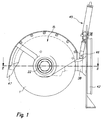
- FIG. 1 shows the entire device with a saw blade 1.
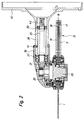
- the saw blade 1 has a round opening 2.
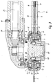
- the saw blade 1 is clamped along the circumference of the opening 2 between two inner rings 3 and 4, which are arranged on both sides of the saw blade 1.
- the rings 3 and 4 are screwed together by three circumferentially arranged screws 5 (only two of which are visible) with each other and with the saw blade 1.
- the screws 5 extend through openings 5 'in the saw blade 1.
- the inner diameter of the rings 3 and 4 is equal to that of the opening 2 of the saw blade 1.
- the distance between the side plates 10, 11 is ensured by a half-ring 17 which extends in the manner shown inwardly a piece and is provided with a slot 18 in which the outer periphery of the saw blade 1 extends into it.
- the saw blade 1 may not touch the inner surfaces of the slot 18, but may nevertheless only have a small distance from them, so that no bone fragments are pulled into the protective cover 15.
- the unit which is formed by the saw blade 1, the inner rings 3, 4, the outer rings 8, 9, the cover plates 12, 13 and the side plates 10, 11 of the protective cover 15, sitting on the drive hub 20, whose outer end with a thread 21 is provided.
- This unit is bolted to the drive hub 20 by the nut 22 and can be easily and quickly replaced by opening this screw.
- the exact fit is ensured by the fact that the saw blade 1 has openings 25 along its circumference, into which pins 26 distributed on the drive hub 20 along its circumference engage.
- a stationary piston / cylinder assembly 45 which engages the protective hood 15 at 46, can be brought to a slaughtered animal in different positions, such as in a position of 23 ° relative to the 0 ° position shown in the separation of abdomen and Sternum (compare DE 10 2004 022 346 ) or in a position of 90 ° to the complete Release of the saw blade 1 when cutting into the lock leg of a slaughtered animal.
- the connection must be solved at 46, but this is easily possible simply because it is only a screw.
- the drive hub is driven via the pinions 30 and 31 by a shaft 35 which is mounted in the housing 36 by means of bearings 37 and in the housing 38 by means of bearings 39.
- the housings 36, 38 are connected to each other by the screw 41.
- the housing 38 merges with the flange 42, which connects to the motor housing.
Landscapes
- Life Sciences & Earth Sciences (AREA)
- Engineering & Computer Science (AREA)
- Mechanical Engineering (AREA)
- Wood Science & Technology (AREA)
- Forests & Forestry (AREA)
- Food Science & Technology (AREA)
- Manipulator (AREA)
- Sawing (AREA)
- Grinding-Machine Dressing And Accessory Apparatuses (AREA)
- Drilling Tools (AREA)
- Finish Polishing, Edge Sharpening, And Grinding By Specific Grinding Devices (AREA)
Description
- Die Erfindung betrifft eine Antriebseinheit gemäß dem Oberbegriff des Anspruchs 1. Eine solche Antriebseinheit ist der
DE 10 2004 022 346 B3 zu entnehmen. - Die der Erfindung zu Grunde liegende Aufgabe besteht darin, eine Antriebseinheit dieser Art zu schaffen, bei der das Sägeblatt einfach auswechselbar ist. Bei einer Einrichtung zum Wechsel des Sägeblatts gemäß der
US 4,909,813 A ist die erforderliche Präzision der Einspannung nicht gegeben. Die entlang des Umfangs vorgesehenen Spanneinrichtungen sind zu umständlich, bringen ein zu großes Gewicht mit sich und führen bei hohen Drehzahlen, sofern auch nur kleinste Ungenauigkeiten vorhanden sind, zu einer Unwucht der sich drehenden Einheit und damit zu Schwingungen, die die Arbeitsweise beeinträchtigen. - Die oben genannte Aufgabe wird mit den Merkmalen des Anspruchs 1 gelöst. Vorteilhafte Weiterbildungen der Erfindung sind den abhängigen Ansprüchen zu entnehmen.
- Die leichte Auswechselbarkeit der gesamten Einheit ermöglicht insbesondere ein sehr schnelles Auswechseln zur Inspektion, zur Reinigung und zum Nachschleifen des Sägeblatts. Die Unterbrechung der Arbeit des Roboters ist nur kurz. Das Abnehmen und Auswechseln des Sägeblatts mit Schutzhaube verhindert auch die Gefahr von Verletzungen der Person, die diese Tätigkeit erledigt. Es bringt erhebliche Handhabungsvorteile mit sich, das Sägeblatt selbst nicht direkt am Roboter wechseln zu müssen.
- Ein Ausführungsbeispiel der Erfindung wird im Folgenden unter Bezugnahme auf die beigefügten Zeichnungen beschrieben. Es stellen dar:
- Figur 1
- ein Ausführungsbeispiel;
- Figur 2
- ein Schnitt in Richtung der Pfeile II-II in
Figur 1 ; - Figur 3
- eine vergrößerte Darstellung des linken Bereichs von
Figur 2 . -
Figur 1 zeigt die gesamte Vorrichtung mit einem Sägeblatt 1. Wie ausFigur 2 zu ersehen, weist das Sägeblatt 1 eine runde Öffnung 2 auf. Das Sägeblatt 1 ist entlang des Umfangs der Öffnung 2 zwischen zwei inneren Ringen 3 und 4 eingespannt, die beidseitig des Sägeblatts 1 angeordnet sind. Die Ringe 3 und 4 sind durch drei entlang des Umfangs angeordnete Schrauben 5 (von denen nur zwei ersichtlich sind) miteinander und mit dem Sägeblatt 1 verschraubt. Die Schrauben 5 erstrecken sich durch Öffnungen 5' im Sägeblatt 1. Der innere Durchmesser der Ringe 3 und 4 ist gleich dem der Öffnung 2 des Sägeblatts 1. Auf den Ringen 3 und 4 sitzen außen jeweils Kugellager 6 beziehungsweise 7, so dass die durch das Sägeblatt 1 und die inneren Ringe 3, 4 gebildete Einheit in den äußeren Ringen 8, 9 drehbar ist, wobei sich das Sägeblatt 1 mit Abstand durch den Zwischenraum zwischen den äußeren Ringen 8 und 9 hindurch erstreckt. Mit den äußeren Ringen 8, 9 sind Seitenplatten 10, 11 einer Schutzhaube 15 fest verbunden (zum Beispiel verschweißt). Die Schutzhaube 15 mit der durch das Sägeblatt 1 und die inneren Ringe 3, 4 gebildeten Einheit dreht sich also mit dem Sägeblatt 1 nicht mit, wenn letzteres angetrieben wird. Die Kugellager 6, 7 sind beidseitig durch Abdeckplatten 12, 13 abgedeckt. Die beiden Seitenplatten 10, 11 der Schutzhaube 15 sind entlang eines Teils ihres Umfangs außen miteinander durch Schrauben 16 verschraubt. Der Abstand zwischen den Seitenplatten 10, 11 wird durch einen Halbring 17 gewährleistet, der sich in der ersichtlichen Weise ein Stück einwärts erstreckt und mit einem Schlitz 18 versehen ist, in der sich der äußere Umfang des Sägeblatts 1 hinein erstreckt. Das Sägeblatt 1 darf die Innenflächen des Schlitzes 18 nicht streifen, darf aber gleichwohl von diesen nur einen geringen Abstand haben, damit keine Knochensplitter in die Schutzhaube 15 eingezogen werden. - Die Einheit, die durch das Sägeblatt 1, die inneren Ringe 3, 4, die äußeren Ringe 8, 9, die Abdeckplatten 12, 13 und die Seitenplatten 10, 11 der Schutzhaube 15 gebildet wird, sitzt auf der Antriebsnabe 20, deren äußeres Ende mit einem Gewinde 21 versehen ist. Diese Einheit ist auf der Antriebsnabe 20 durch die Mutter 22 verschraubt und kann durch Öffnen dieser Schraubverbindung einfach und schnell ausgewechselt werden. Der exakte Sitz ist dadurch gewährleistet, dass das Sägeblatt 1 entlang seines Umfanges Öffnungen 25 aufweist, in die auf der Antriebsnabe 20 entlang ihres Umfangs verteilte Stifte 26 eingreifen. Bei Drehung der Antriebsnabe 20 drehen sich somit die inneren Ringe 3, 4 und des Sägeblatts 1 mit, während der äußere Teil dieser Einheit, gebildet durch die äußeren Ringe 8, 9, die Abdeckplatten 12, 13 und die Seitenplatten 10, 11 der Schutzhaube 15 mit Eingreifnase 47, wie in
Figur 1 gezeigt, durch eine stationäre Kolben-/Zylinderanordnung 45, die an der Schutzhaube 15 bei 46 angreift, gegenüber einem Schlachttier in verschiedene Positionen gebracht werden kann, so z.B. in eine Stellung von 23° gegenüber der gezeigten 0°-Stellung beim Trennen von Bauch und Brustbein (vergleicheDE 10 2004 022 346 ) oder in eine Stellung von 90° zur kompletten Freigabe des Sägeblatts 1 beim Einschnitt in das Schlossbein eines geschlachteten Tieres. Beim Auswechseln der oben genannten Einheit muss selbstverständlich auch die Verbindung bei 46 gelöst werden, was aber problemlos einfach möglich ist, da es sich dabei nur um eine Schraube handelt. - Die Antriebsnabe wird über die Ritzel 30 und 31 durch eine Welle 35 angetrieben, die im Gehäuse 36 mittels Lager 37 und im Gehäuse 38 mittels Lager 39 gelagert ist. Die Gehäuse 36, 38 sind durch die Schraube 41 miteinander verbunden. Das Gehäuse 38 geht in den Flansch 42 über, der an das Motorgehäuse anschließt. Beim Aufsetzen dieser Roboteranschlussplatte auf das Motorgehäuse des Roboters gelangt das Ende 43 der Welle 35 in Eingriff mit der Antriebswelle des Motors des Roboters.
Claims (8)
- Antriebseinheit mit einem rotierenden in einer Schutzhaube (15) drehbar angeordneten Sägeblatt (1) zum Anschluss an einen Roboter, gebildet durch ein an den Roboter anschließbares Gehäuse (36, 38, 42), in dem eine Welle (35) gelagert ist, durch die unter Zwischenschaltung eines Getriebes (30, 31) das Sägeblatt (1) antreibbar ist, dadurch gekennzeichnet, dass das Sägeblatt (1) zwischen zwei beiderseits an dem Sägeblatt (1) angeordneten und dieses aufnehmenden, sowie miteinander und mit diesem fest verbundenen inneren Ringen (3, 4) gehalten wird, die drehbar in nicht mitdrehenden mit der Schutzhaube verbundenen äußeren Ringen (8, 9) aufgenommen sind, und dass die durch das Sägeblatt (1), die inneren Ringe (3, 4), Abdeckplatten (12, 13), die Schutzhaube (15) und die äußeren Ringe (8, 9) gebildete Einheit auf einer vom Getriebe (30, 31) angetriebenen Antriebsnabe (20) lösbar befestigt ist.
- Antriebseinheit nach Anspruch 1, dadurch gekennzeichnet, dass die mit dem Sägeblatt (1) verbundenen inneren Ringe (3, 4) in den äußeren Ringen (8, 9) mittels Kugellager (6, 7) gelagert sind, die von den Abdeckplatten (12, 13) abgedeckt sind.
- Antriebseinheit nach Anspruch 1 oder 2, dadurch gekennzeichnet, dass die genannte Einheit (1, 3, 4, 8, 9, 12, 13, 15) mit der Antriebsnabe (20) verschraubbar (21, 22) ist.1
- Antriebseinheit nach einem der Ansprüche 1 bis 3, dadurch gekennzeichnet, dass das Ende der Antriebsnabe (20) mit einem Gewinde (21) versehen ist, auf das eine Mutter (22) aufgeschraubt wird.
- Antriebseinheit nach einem der Ansprüche 1 bis 4, dadurch gekennzeichnet, dass die die Säge (1) enthaltende Einheit gegenüber der Antriebsnabe (20) durch den Eingriff von Stiften (26) in Öffnungen (25) formschlüssig aufgenommen ist, wobei eines der Elemente Zapfen/Öffnungen (25, 26) an der Antriebsnabe (20) und das andere an einem der inneren Ringe (3, 4) vorgesehen ist.
- Antriebseinheit nach einem der Ansprüche 1 bis 5, dadurch gekennzeichnet, dass die beiden beidseitig des Sägeblattes (1) einander gegenüberliegend angeordneten inneren Ringe (3, 4) miteinander und mit dem Sägeblatt (1) verschraubt (5) sind, wobei die Schrauben (5) sich durch entsprechende Öffnungen (5') im Sägeblatt (1) hindurch erstrecken.
- Antriebseinheit nach einem der Ansprüche 1 bis 6, dadurch gekennzeichnet, dass der äußere Umfang des Sägeblatts (1) mit geringem Abstand im Schlitz (18) eines Halbringes (17) geführt ist, der zwischen den Seitenplatten (10, 11) der Schutzhaube (15) angeordnet ist.
- Antriebseinheit nach einem der Ansprüche 1 bis 7, dadurch gekennzeichnet, dass an der Schutzhaube (15) ein stationäres Stellmittel (45) angreift.
Applications Claiming Priority (2)
| Application Number | Priority Date | Filing Date | Title |
|---|---|---|---|
| DE200620007224 DE202006007224U1 (de) | 2006-04-28 | 2006-04-28 | Antriebseinheit mit einem rotierenden Sägeblatt zum Anschluss an einen Roboter |
| PCT/EP2007/003583 WO2007124893A1 (de) | 2006-04-28 | 2007-04-24 | Antriebseinheit mit einem rotierenden sägeblatt zum anschluss an einen roboter |
Publications (2)
| Publication Number | Publication Date |
|---|---|
| EP2012984A1 EP2012984A1 (de) | 2009-01-14 |
| EP2012984B1 true EP2012984B1 (de) | 2016-08-10 |
Family
ID=38222610
Family Applications (1)
| Application Number | Title | Priority Date | Filing Date |
|---|---|---|---|
| EP07724513.2A Not-in-force EP2012984B1 (de) | 2006-04-28 | 2007-04-24 | Antriebseinheit mit einem rotierenden sägeblatt zum anschluss an einen roboter |
Country Status (12)
| Country | Link |
|---|---|
| US (1) | US8291804B2 (de) |
| EP (1) | EP2012984B1 (de) |
| JP (1) | JP5036805B2 (de) |
| KR (1) | KR101169837B1 (de) |
| BR (1) | BRPI0710801B1 (de) |
| DE (1) | DE202006007224U1 (de) |
| DK (1) | DK2012984T3 (de) |
| ES (1) | ES2601801T3 (de) |
| PL (1) | PL2012984T3 (de) |
| PT (1) | PT2012984T (de) |
| RU (1) | RU2402419C2 (de) |
| WO (1) | WO2007124893A1 (de) |
Families Citing this family (7)
| Publication number | Priority date | Publication date | Assignee | Title |
|---|---|---|---|---|
| US20110017043A1 (en) * | 2009-07-21 | 2011-01-27 | Angelo Don L | Saw blade and saw blade assembly |
| DE202010000260U1 (de) * | 2010-02-26 | 2010-06-02 | Freund Maschinenfabrik Gmbh & Co. Kg | Ständer-Kreismesser |
| BR102012030914B1 (pt) * | 2012-12-04 | 2015-12-22 | Ademar Birck | eixo bipartido, conjunto eixo-cubo e uso dos mesmos |
| US10882123B2 (en) | 2015-02-25 | 2021-01-05 | Milwaukee Electric Tool Corporation | Miter saw |
| US10946546B2 (en) | 2017-09-01 | 2021-03-16 | Paper Converting Machine Company | Apparatus and method for automated blade change for tissue saw |
| EP4171856B1 (de) * | 2020-06-25 | 2025-07-30 | Festool GmbH | Tauchsäge mit schnittindikatoren und verfahren zum betrieb einer tauchsäge |
| KR102700835B1 (ko) * | 2023-11-29 | 2024-08-30 | (주)연암테크 | 동물용 복부 절개장치 |
Family Cites Families (11)
| Publication number | Priority date | Publication date | Assignee | Title |
|---|---|---|---|---|
| US2842908A (en) * | 1957-03-29 | 1958-07-15 | American Chain & Cable Co | Abrasive cutting wheel mounting and guard |
| US2981300A (en) * | 1960-03-22 | 1961-04-25 | Birdsboro Corp | Saw blade mounting |
| US3353306A (en) * | 1964-01-31 | 1967-11-21 | Norton Co | Hub mounting for grinding wheels |
| JPS5154456Y2 (de) * | 1973-07-05 | 1976-12-27 | ||
| US4576073A (en) * | 1983-07-01 | 1986-03-18 | Stinson Robert J | Saw blade guard |
| US4909113A (en) * | 1988-11-01 | 1990-03-20 | Mariupolskii Metallurgicheskii Institut | Device for clamping a circular saw blade |
| US4909813A (en) * | 1989-05-30 | 1990-03-20 | Industrial Filter & Pump Mfg. Co. | Jet pulse extender |
| DE10041210C2 (de) * | 1999-08-30 | 2002-07-11 | Otto Martin Maschb Gmbh Fa | Kreissägemaschine |
| DE102004024077A1 (de) * | 2004-05-13 | 2005-12-29 | Freund Maschinenfabrik Gmbh & Co. Kg | Vorrichtung zum Zerlegen von Tierkörpern |
| DE102004022346B3 (de) * | 2004-04-28 | 2005-09-08 | Schmid & Wezel Gmbh & Co | Schneidwerkzeug zum Aufschneiden von Schlachttieren |
| RU2274518C2 (ru) * | 2004-07-08 | 2006-04-20 | Общество с ограниченной ответственностью "Центр Новых Технологий "НУР" | Пила ручная электрическая дисковая (варианты) |
-
2006
- 2006-04-28 DE DE200620007224 patent/DE202006007224U1/de not_active Expired - Lifetime
-
2007
- 2007-04-24 JP JP2009506963A patent/JP5036805B2/ja not_active Expired - Fee Related
- 2007-04-24 ES ES07724513.2T patent/ES2601801T3/es active Active
- 2007-04-24 DK DK07724513.2T patent/DK2012984T3/en active
- 2007-04-24 RU RU2008145658A patent/RU2402419C2/ru active
- 2007-04-24 KR KR1020087028943A patent/KR101169837B1/ko not_active Expired - Fee Related
- 2007-04-24 EP EP07724513.2A patent/EP2012984B1/de not_active Not-in-force
- 2007-04-24 BR BRPI0710801-0A patent/BRPI0710801B1/pt not_active IP Right Cessation
- 2007-04-24 PT PT77245132T patent/PT2012984T/pt unknown
- 2007-04-24 PL PL07724513T patent/PL2012984T3/pl unknown
- 2007-04-24 WO PCT/EP2007/003583 patent/WO2007124893A1/de not_active Ceased
-
2008
- 2008-10-02 US US12/244,628 patent/US8291804B2/en active Active
Also Published As
| Publication number | Publication date |
|---|---|
| BRPI0710801A2 (pt) | 2011-08-23 |
| US20090025521A1 (en) | 2009-01-29 |
| EP2012984A1 (de) | 2009-01-14 |
| PT2012984T (pt) | 2016-11-01 |
| RU2008145658A (ru) | 2010-06-10 |
| DE202006007224U1 (de) | 2007-07-05 |
| ES2601801T3 (es) | 2017-02-16 |
| KR20090015086A (ko) | 2009-02-11 |
| JP5036805B2 (ja) | 2012-09-26 |
| WO2007124893A1 (de) | 2007-11-08 |
| RU2402419C2 (ru) | 2010-10-27 |
| KR101169837B1 (ko) | 2012-07-30 |
| US8291804B2 (en) | 2012-10-23 |
| PL2012984T3 (pl) | 2017-01-31 |
| DK2012984T3 (en) | 2016-10-10 |
| BRPI0710801B1 (pt) | 2020-06-02 |
| JP2009535223A (ja) | 2009-10-01 |
Similar Documents
| Publication | Publication Date | Title |
|---|---|---|
| DE1632808C3 (de) | Gehäuse für Scheibenmäher | |
| DE2641370C2 (de) | Gerät zum Vernichten von Mikrofilmen und dergleichen | |
| EP2012984A1 (de) | Antriebseinheit mit einem rotierenden sägeblatt zum anschluss an einen roboter | |
| DE2320919C2 (de) | Schnellwechsel-Spannvorrichtung für Rotationswerkzeuge, insbesondere für Kreissägen | |
| DE2303942C2 (de) | Drehzahlbegrenzungseinrichtung für Werkzeugmaschinen mit pneumatisch drehangetriebener Werkzeugspindel | |
| DE4338903A1 (de) | Zerkleinerungsmaschine und Einrichtung zur Einstellung des Spaltes einer solchen Zerkleinerungsmaschine | |
| DE10015093B4 (de) | Vorrichtung zur verdrehbaren Kopplung zweier koaxialer Anschlußelemente | |
| EP2509749B1 (de) | Elektrodenschleifvorrichtung | |
| DE19958802A1 (de) | Aufnahme- und Antriebsvorrichtung für ein Rotationsmesser | |
| DE29613397U1 (de) | Mähvorrichtung | |
| EP0173898A1 (de) | Schutzvorrichtung für eine Welle | |
| DE102007040046B4 (de) | Rotorshredder | |
| EP3552693A1 (de) | Siebrundbeschicker und verschleissblech für den ausstreicharm eines siebrundbeschickers | |
| DE102011104102A1 (de) | Vorrichtung zum Schälen von Schläuchen | |
| DE3728866A1 (de) | Schlitzwandfraese | |
| EP4331365B1 (de) | Knetmaschine für nahrungsmittelteige mit not-halt-einrichtung und verfahren zur steuerung einer knetmaschine für nahrungsmittelteige | |
| EP1591014A2 (de) | Schneidwerkzeug zum Aufschneiden von Schlachttieren | |
| EP2845649A1 (de) | Schneideinrichtung | |
| DE2503830A1 (de) | Fraeswerkzeug, insbesondere zum bearbeiten von kanten von werkstuecken | |
| DE102012106188B4 (de) | Verfahren zum Demontieren und Verfahren zum Montieren eines Schneidwerkzeugs einer Werkzeuganordnung zum Herstellen von Wandschlitzen | |
| EP0987201B1 (de) | Klinge an einer Mischschnecke, insbesondere in einen Futtermischwagen | |
| EP3501354B1 (de) | Gewürzmühlenmahlwerk | |
| DE1169393B (de) | Getriebe fuer den Antrieb eines Kohlenhobels | |
| EP3323572A1 (de) | Vorrichtung zum zerspanen von holz | |
| DE102005010876A1 (de) | Innenbelüftete Schleifvorrichtung |
Legal Events
| Date | Code | Title | Description |
|---|---|---|---|
| PUAI | Public reference made under article 153(3) epc to a published international application that has entered the european phase |
Free format text: ORIGINAL CODE: 0009012 |
|
| 17P | Request for examination filed |
Effective date: 20080902 |
|
| AK | Designated contracting states |
Kind code of ref document: A1 Designated state(s): AT BE BG CH CY CZ DE DK EE ES FI FR GB GR HU IE IS IT LI LT LU LV MC MT NL PL PT RO SE SI SK TR |
|
| AX | Request for extension of the european patent |
Extension state: AL BA HR MK RS |
|
| 17Q | First examination report despatched |
Effective date: 20091013 |
|
| DAX | Request for extension of the european patent (deleted) | ||
| GRAP | Despatch of communication of intention to grant a patent |
Free format text: ORIGINAL CODE: EPIDOSNIGR1 |
|
| INTG | Intention to grant announced |
Effective date: 20160304 |
|
| RAP1 | Party data changed (applicant data changed or rights of an application transferred) |
Owner name: SCHMID & WEZEL GMBH & CO. KG |
|
| GRAS | Grant fee paid |
Free format text: ORIGINAL CODE: EPIDOSNIGR3 |
|
| GRAA | (expected) grant |
Free format text: ORIGINAL CODE: 0009210 |
|
| AK | Designated contracting states |
Kind code of ref document: B1 Designated state(s): AT BE BG CH CY CZ DE DK EE ES FI FR GB GR HU IE IS IT LI LT LU LV MC MT NL PL PT RO SE SI SK TR |
|
| REG | Reference to a national code |
Ref country code: GB Ref legal event code: FG4D Free format text: NOT ENGLISH |
|
| REG | Reference to a national code |
Ref country code: CH Ref legal event code: EP Ref country code: AT Ref legal event code: REF Ref document number: 818557 Country of ref document: AT Kind code of ref document: T Effective date: 20160815 |
|
| REG | Reference to a national code |
Ref country code: CH Ref legal event code: NV Representative=s name: DREISS PATENTANWAELTE PARTG MBB, DE |
|
| REG | Reference to a national code |
Ref country code: IE Ref legal event code: FG4D Free format text: LANGUAGE OF EP DOCUMENT: GERMAN |
|
| REG | Reference to a national code |
Ref country code: DE Ref legal event code: R096 Ref document number: 502007015002 Country of ref document: DE |
|
| REG | Reference to a national code |
Ref country code: DK Ref legal event code: T3 Effective date: 20161005 |
|
| REG | Reference to a national code |
Ref country code: PT Ref legal event code: SC4A Ref document number: 2012984 Country of ref document: PT Date of ref document: 20161101 Kind code of ref document: T Free format text: AVAILABILITY OF NATIONAL TRANSLATION Effective date: 20161021 |
|
| REG | Reference to a national code |
Ref country code: NL Ref legal event code: FP |
|
| REG | Reference to a national code |
Ref country code: LT Ref legal event code: MG4D |
|
| PG25 | Lapsed in a contracting state [announced via postgrant information from national office to epo] |
Ref country code: IS Free format text: LAPSE BECAUSE OF FAILURE TO SUBMIT A TRANSLATION OF THE DESCRIPTION OR TO PAY THE FEE WITHIN THE PRESCRIBED TIME-LIMIT Effective date: 20161210 Ref country code: LT Free format text: LAPSE BECAUSE OF FAILURE TO SUBMIT A TRANSLATION OF THE DESCRIPTION OR TO PAY THE FEE WITHIN THE PRESCRIBED TIME-LIMIT Effective date: 20160810 |
|
| REG | Reference to a national code |
Ref country code: ES Ref legal event code: FG2A Ref document number: 2601801 Country of ref document: ES Kind code of ref document: T3 Effective date: 20170216 |
|
| PG25 | Lapsed in a contracting state [announced via postgrant information from national office to epo] |
Ref country code: SE Free format text: LAPSE BECAUSE OF FAILURE TO SUBMIT A TRANSLATION OF THE DESCRIPTION OR TO PAY THE FEE WITHIN THE PRESCRIBED TIME-LIMIT Effective date: 20160810 Ref country code: LV Free format text: LAPSE BECAUSE OF FAILURE TO SUBMIT A TRANSLATION OF THE DESCRIPTION OR TO PAY THE FEE WITHIN THE PRESCRIBED TIME-LIMIT Effective date: 20160810 Ref country code: GR Free format text: LAPSE BECAUSE OF FAILURE TO SUBMIT A TRANSLATION OF THE DESCRIPTION OR TO PAY THE FEE WITHIN THE PRESCRIBED TIME-LIMIT Effective date: 20161111 |
|
| REG | Reference to a national code |
Ref country code: FR Ref legal event code: PLFP Year of fee payment: 11 |
|
| PG25 | Lapsed in a contracting state [announced via postgrant information from national office to epo] |
Ref country code: EE Free format text: LAPSE BECAUSE OF FAILURE TO SUBMIT A TRANSLATION OF THE DESCRIPTION OR TO PAY THE FEE WITHIN THE PRESCRIBED TIME-LIMIT Effective date: 20160810 Ref country code: RO Free format text: LAPSE BECAUSE OF FAILURE TO SUBMIT A TRANSLATION OF THE DESCRIPTION OR TO PAY THE FEE WITHIN THE PRESCRIBED TIME-LIMIT Effective date: 20160810 |
|
| REG | Reference to a national code |
Ref country code: DE Ref legal event code: R097 Ref document number: 502007015002 Country of ref document: DE |
|
| PG25 | Lapsed in a contracting state [announced via postgrant information from national office to epo] |
Ref country code: CZ Free format text: LAPSE BECAUSE OF FAILURE TO SUBMIT A TRANSLATION OF THE DESCRIPTION OR TO PAY THE FEE WITHIN THE PRESCRIBED TIME-LIMIT Effective date: 20160810 Ref country code: BG Free format text: LAPSE BECAUSE OF FAILURE TO SUBMIT A TRANSLATION OF THE DESCRIPTION OR TO PAY THE FEE WITHIN THE PRESCRIBED TIME-LIMIT Effective date: 20161110 Ref country code: SK Free format text: LAPSE BECAUSE OF FAILURE TO SUBMIT A TRANSLATION OF THE DESCRIPTION OR TO PAY THE FEE WITHIN THE PRESCRIBED TIME-LIMIT Effective date: 20160810 |
|
| PLBE | No opposition filed within time limit |
Free format text: ORIGINAL CODE: 0009261 |
|
| STAA | Information on the status of an ep patent application or granted ep patent |
Free format text: STATUS: NO OPPOSITION FILED WITHIN TIME LIMIT |
|
| 26N | No opposition filed |
Effective date: 20170511 |
|
| PG25 | Lapsed in a contracting state [announced via postgrant information from national office to epo] |
Ref country code: SI Free format text: LAPSE BECAUSE OF FAILURE TO SUBMIT A TRANSLATION OF THE DESCRIPTION OR TO PAY THE FEE WITHIN THE PRESCRIBED TIME-LIMIT Effective date: 20160810 |
|
| GBPC | Gb: european patent ceased through non-payment of renewal fee |
Effective date: 20170424 |
|
| REG | Reference to a national code |
Ref country code: IE Ref legal event code: MM4A |
|
| PG25 | Lapsed in a contracting state [announced via postgrant information from national office to epo] |
Ref country code: MC Free format text: LAPSE BECAUSE OF FAILURE TO SUBMIT A TRANSLATION OF THE DESCRIPTION OR TO PAY THE FEE WITHIN THE PRESCRIBED TIME-LIMIT Effective date: 20160810 |
|
| PG25 | Lapsed in a contracting state [announced via postgrant information from national office to epo] |
Ref country code: LU Free format text: LAPSE BECAUSE OF NON-PAYMENT OF DUE FEES Effective date: 20170424 Ref country code: GB Free format text: LAPSE BECAUSE OF NON-PAYMENT OF DUE FEES Effective date: 20170424 |
|
| REG | Reference to a national code |
Ref country code: FR Ref legal event code: PLFP Year of fee payment: 12 |
|
| PG25 | Lapsed in a contracting state [announced via postgrant information from national office to epo] |
Ref country code: IE Free format text: LAPSE BECAUSE OF NON-PAYMENT OF DUE FEES Effective date: 20170424 |
|
| PG25 | Lapsed in a contracting state [announced via postgrant information from national office to epo] |
Ref country code: MT Free format text: LAPSE BECAUSE OF FAILURE TO SUBMIT A TRANSLATION OF THE DESCRIPTION OR TO PAY THE FEE WITHIN THE PRESCRIBED TIME-LIMIT Effective date: 20160810 |
|
| PG25 | Lapsed in a contracting state [announced via postgrant information from national office to epo] |
Ref country code: HU Free format text: LAPSE BECAUSE OF FAILURE TO SUBMIT A TRANSLATION OF THE DESCRIPTION OR TO PAY THE FEE WITHIN THE PRESCRIBED TIME-LIMIT; INVALID AB INITIO Effective date: 20070424 |
|
| PG25 | Lapsed in a contracting state [announced via postgrant information from national office to epo] |
Ref country code: CY Free format text: LAPSE BECAUSE OF NON-PAYMENT OF DUE FEES Effective date: 20160810 |
|
| PG25 | Lapsed in a contracting state [announced via postgrant information from national office to epo] |
Ref country code: TR Free format text: LAPSE BECAUSE OF FAILURE TO SUBMIT A TRANSLATION OF THE DESCRIPTION OR TO PAY THE FEE WITHIN THE PRESCRIBED TIME-LIMIT Effective date: 20160810 |
|
| PGFP | Annual fee paid to national office [announced via postgrant information from national office to epo] |
Ref country code: PL Payment date: 20200319 Year of fee payment: 14 |
|
| PGFP | Annual fee paid to national office [announced via postgrant information from national office to epo] |
Ref country code: ES Payment date: 20200516 Year of fee payment: 14 Ref country code: DE Payment date: 20200615 Year of fee payment: 14 Ref country code: PT Payment date: 20200423 Year of fee payment: 14 Ref country code: NL Payment date: 20200420 Year of fee payment: 14 Ref country code: FR Payment date: 20200421 Year of fee payment: 14 Ref country code: FI Payment date: 20200417 Year of fee payment: 14 Ref country code: DK Payment date: 20200423 Year of fee payment: 14 Ref country code: CH Payment date: 20200423 Year of fee payment: 14 |
|
| PGFP | Annual fee paid to national office [announced via postgrant information from national office to epo] |
Ref country code: BE Payment date: 20200420 Year of fee payment: 14 Ref country code: IT Payment date: 20200423 Year of fee payment: 14 |
|
| PGFP | Annual fee paid to national office [announced via postgrant information from national office to epo] |
Ref country code: AT Payment date: 20200421 Year of fee payment: 14 |
|
| REG | Reference to a national code |
Ref country code: DE Ref legal event code: R119 Ref document number: 502007015002 Country of ref document: DE |
|
| REG | Reference to a national code |
Ref country code: FI Ref legal event code: MAE |
|
| REG | Reference to a national code |
Ref country code: DK Ref legal event code: EBP Effective date: 20210430 |
|
| REG | Reference to a national code |
Ref country code: NL Ref legal event code: MM Effective date: 20210501 |
|
| REG | Reference to a national code |
Ref country code: AT Ref legal event code: MM01 Ref document number: 818557 Country of ref document: AT Kind code of ref document: T Effective date: 20210424 |
|
| REG | Reference to a national code |
Ref country code: BE Ref legal event code: MM Effective date: 20210430 |
|
| PG25 | Lapsed in a contracting state [announced via postgrant information from national office to epo] |
Ref country code: FR Free format text: LAPSE BECAUSE OF NON-PAYMENT OF DUE FEES Effective date: 20210430 Ref country code: DE Free format text: LAPSE BECAUSE OF NON-PAYMENT OF DUE FEES Effective date: 20211103 Ref country code: PT Free format text: LAPSE BECAUSE OF NON-PAYMENT OF DUE FEES Effective date: 20211025 Ref country code: FI Free format text: LAPSE BECAUSE OF NON-PAYMENT OF DUE FEES Effective date: 20210424 Ref country code: LI Free format text: LAPSE BECAUSE OF NON-PAYMENT OF DUE FEES Effective date: 20210430 Ref country code: CH Free format text: LAPSE BECAUSE OF NON-PAYMENT OF DUE FEES Effective date: 20210430 Ref country code: AT Free format text: LAPSE BECAUSE OF NON-PAYMENT OF DUE FEES Effective date: 20210424 |
|
| PG25 | Lapsed in a contracting state [announced via postgrant information from national office to epo] |
Ref country code: NL Free format text: LAPSE BECAUSE OF NON-PAYMENT OF DUE FEES Effective date: 20210501 |
|
| PG25 | Lapsed in a contracting state [announced via postgrant information from national office to epo] |
Ref country code: DK Free format text: LAPSE BECAUSE OF NON-PAYMENT OF DUE FEES Effective date: 20210430 |
|
| REG | Reference to a national code |
Ref country code: ES Ref legal event code: FD2A Effective date: 20220705 |
|
| PG25 | Lapsed in a contracting state [announced via postgrant information from national office to epo] |
Ref country code: ES Free format text: LAPSE BECAUSE OF NON-PAYMENT OF DUE FEES Effective date: 20210425 Ref country code: BE Free format text: LAPSE BECAUSE OF NON-PAYMENT OF DUE FEES Effective date: 20210430 |
|
| PG25 | Lapsed in a contracting state [announced via postgrant information from national office to epo] |
Ref country code: PL Free format text: LAPSE BECAUSE OF NON-PAYMENT OF DUE FEES Effective date: 20210424 |
|
| PG25 | Lapsed in a contracting state [announced via postgrant information from national office to epo] |
Ref country code: IT Free format text: LAPSE BECAUSE OF NON-PAYMENT OF DUE FEES Effective date: 20200424 |
|
| PG25 | Lapsed in a contracting state [announced via postgrant information from national office to epo] |
Ref country code: IT Free format text: LAPSE BECAUSE OF NON-PAYMENT OF DUE FEES Effective date: 20210424 |