EP2014401B1 - Vorrichtung und Verfahren zum Schweißen von Werkstücken - Google Patents
Vorrichtung und Verfahren zum Schweißen von Werkstücken Download PDFInfo
- Publication number
- EP2014401B1 EP2014401B1 EP08012421A EP08012421A EP2014401B1 EP 2014401 B1 EP2014401 B1 EP 2014401B1 EP 08012421 A EP08012421 A EP 08012421A EP 08012421 A EP08012421 A EP 08012421A EP 2014401 B1 EP2014401 B1 EP 2014401B1
- Authority
- EP
- European Patent Office
- Prior art keywords
- welding
- nozzle
- weld seam
- cryogenic
- robot
- Prior art date
- Legal status (The legal status is an assumption and is not a legal conclusion. Google has not performed a legal analysis and makes no representation as to the accuracy of the status listed.)
- Not-in-force
Links
- 238000003466 welding Methods 0.000 title claims description 81
- 238000000034 method Methods 0.000 title claims description 27
- 239000000203 mixture Substances 0.000 claims description 14
- 238000002156 mixing Methods 0.000 claims description 7
- 239000007788 liquid Substances 0.000 claims description 5
- 239000008188 pellet Substances 0.000 claims description 5
- 230000004927 fusion Effects 0.000 claims description 2
- 230000003213 activating effect Effects 0.000 claims 1
- 239000003795 chemical substances by application Substances 0.000 description 14
- 238000001816 cooling Methods 0.000 description 6
- 239000007789 gas Substances 0.000 description 5
- 239000004033 plastic Substances 0.000 description 5
- 229920003023 plastic Polymers 0.000 description 5
- 238000005299 abrasion Methods 0.000 description 3
- 229910052782 aluminium Inorganic materials 0.000 description 3
- XAGFODPZIPBFFR-UHFFFAOYSA-N aluminium Chemical compound [Al] XAGFODPZIPBFFR-UHFFFAOYSA-N 0.000 description 3
- 239000011521 glass Substances 0.000 description 3
- 239000012535 impurity Substances 0.000 description 3
- 238000005304 joining Methods 0.000 description 3
- 238000005554 pickling Methods 0.000 description 3
- 238000005406 washing Methods 0.000 description 3
- IJGRMHOSHXDMSA-UHFFFAOYSA-N Atomic nitrogen Chemical compound N#N IJGRMHOSHXDMSA-UHFFFAOYSA-N 0.000 description 2
- 238000004140 cleaning Methods 0.000 description 2
- 230000007547 defect Effects 0.000 description 2
- 230000000694 effects Effects 0.000 description 2
- 229910001338 liquidmetal Inorganic materials 0.000 description 2
- 239000000463 material Substances 0.000 description 2
- 238000003860 storage Methods 0.000 description 2
- CURLTUGMZLYLDI-UHFFFAOYSA-N Carbon dioxide Chemical compound O=C=O CURLTUGMZLYLDI-UHFFFAOYSA-N 0.000 description 1
- 230000000454 anti-cipatory effect Effects 0.000 description 1
- 230000009286 beneficial effect Effects 0.000 description 1
- 230000015572 biosynthetic process Effects 0.000 description 1
- 235000011089 carbon dioxide Nutrition 0.000 description 1
- 238000000576 coating method Methods 0.000 description 1
- 239000000112 cooling gas Substances 0.000 description 1
- 230000001934 delay Effects 0.000 description 1
- 238000011161 development Methods 0.000 description 1
- 230000018109 developmental process Effects 0.000 description 1
- 238000010894 electron beam technology Methods 0.000 description 1
- 238000001704 evaporation Methods 0.000 description 1
- 230000008020 evaporation Effects 0.000 description 1
- 239000003925 fat Substances 0.000 description 1
- 239000004088 foaming agent Substances 0.000 description 1
- 239000011261 inert gas Substances 0.000 description 1
- 238000004519 manufacturing process Methods 0.000 description 1
- 229910052751 metal Inorganic materials 0.000 description 1
- 239000002184 metal Substances 0.000 description 1
- 239000002991 molded plastic Substances 0.000 description 1
- 229910052757 nitrogen Inorganic materials 0.000 description 1
- 239000003921 oil Substances 0.000 description 1
- 238000002360 preparation method Methods 0.000 description 1
- 239000000344 soap Substances 0.000 description 1
- 239000007787 solid Substances 0.000 description 1
- 239000007921 spray Substances 0.000 description 1
- 239000000126 substance Substances 0.000 description 1
Images
Classifications
-
- B—PERFORMING OPERATIONS; TRANSPORTING
- B23—MACHINE TOOLS; METAL-WORKING NOT OTHERWISE PROVIDED FOR
- B23K—SOLDERING OR UNSOLDERING; WELDING; CLADDING OR PLATING BY SOLDERING OR WELDING; CUTTING BY APPLYING HEAT LOCALLY, e.g. FLAME CUTTING; WORKING BY LASER BEAM
- B23K5/00—Gas flame welding
- B23K5/213—Preliminary treatment
-
- B—PERFORMING OPERATIONS; TRANSPORTING
- B23—MACHINE TOOLS; METAL-WORKING NOT OTHERWISE PROVIDED FOR
- B23K—SOLDERING OR UNSOLDERING; WELDING; CLADDING OR PLATING BY SOLDERING OR WELDING; CUTTING BY APPLYING HEAT LOCALLY, e.g. FLAME CUTTING; WORKING BY LASER BEAM
- B23K26/00—Working by laser beam, e.g. welding, cutting or boring
- B23K26/60—Preliminary treatment
-
- B—PERFORMING OPERATIONS; TRANSPORTING
- B23—MACHINE TOOLS; METAL-WORKING NOT OTHERWISE PROVIDED FOR
- B23K—SOLDERING OR UNSOLDERING; WELDING; CLADDING OR PLATING BY SOLDERING OR WELDING; CUTTING BY APPLYING HEAT LOCALLY, e.g. FLAME CUTTING; WORKING BY LASER BEAM
- B23K26/00—Working by laser beam, e.g. welding, cutting or boring
- B23K26/70—Auxiliary operations or equipment
- B23K26/702—Auxiliary equipment
- B23K26/703—Cooling arrangements
-
- B—PERFORMING OPERATIONS; TRANSPORTING
- B23—MACHINE TOOLS; METAL-WORKING NOT OTHERWISE PROVIDED FOR
- B23K—SOLDERING OR UNSOLDERING; WELDING; CLADDING OR PLATING BY SOLDERING OR WELDING; CUTTING BY APPLYING HEAT LOCALLY, e.g. FLAME CUTTING; WORKING BY LASER BEAM
- B23K37/00—Auxiliary devices or processes, not specially adapted for a procedure covered by only one of the other main groups of this subclass
- B23K37/003—Cooling means for welding or cutting
-
- B—PERFORMING OPERATIONS; TRANSPORTING
- B23—MACHINE TOOLS; METAL-WORKING NOT OTHERWISE PROVIDED FOR
- B23K—SOLDERING OR UNSOLDERING; WELDING; CLADDING OR PLATING BY SOLDERING OR WELDING; CUTTING BY APPLYING HEAT LOCALLY, e.g. FLAME CUTTING; WORKING BY LASER BEAM
- B23K9/00—Arc welding or cutting
- B23K9/235—Preliminary treatment
-
- B—PERFORMING OPERATIONS; TRANSPORTING
- B23—MACHINE TOOLS; METAL-WORKING NOT OTHERWISE PROVIDED FOR
- B23K—SOLDERING OR UNSOLDERING; WELDING; CLADDING OR PLATING BY SOLDERING OR WELDING; CUTTING BY APPLYING HEAT LOCALLY, e.g. FLAME CUTTING; WORKING BY LASER BEAM
- B23K9/00—Arc welding or cutting
- B23K9/32—Accessories
Definitions
- the present invention relates to an apparatus and a method for welding workpieces.
- Heat welding processes include, but are not limited to, fire welding, gas fusion welding, manual arc welding, resistance welding, laser beam welding, aluminothermic welding, and electron beam welding.
- drawing agents such as fats, oils, soaps and coatings. This reduces the wear on the tool and improves the surface finish of the workpiece.
- drawing agents leave residues on the surface after the forming process. To weld the molded parts, they must be cleaned of the drawing agent residues because the foaming agent substances do not allow high quality welding. The removal of the drawing agent by washing or pickling is very complex and polluting, since the entire component must be cleaned.
- cryogenic media For surface cleaning, cleaning with CO 2 pellets and CO 2 jet is known.
- the temperature of such cryogenic media is from -50 ° C to -196 ° C.
- EP 1 319 460 A1 a method for welding preparation of workpieces.
- this method it is provided to arrange the two welding edges of two workpieces to be connected to one another next to each other and to irradiate the welding edges with a CO 2 jet in order to remove impurities from the workpiece surface in this way.
- the device has a housing with a nozzle for emitting a cryogenic medium and with an exhaust.
- the housing can be placed tightly on a workpiece surface by means of a seal. This is to prevent gases from entering the weld during cooling by means of cryogenic CO 2 , during evaporation of the cryogenic CO 2 , and in this way the quality of the weld is influenced.
- the apparatus may include connection means to be connected to a welding apparatus so as to be disposed behind the welding apparatus in the welding direction.
- the fastening means may be designed such that the position of the device with respect to the welding device is adjustable. It is envisaged to arrange the device about 60 to 90 mm behind the welding device. With this device delays are to be minimized after the welding process effectively.
- the device should be suitable for any welding technique.
- the object of the invention is to provide a method and a device with which it is possible for drawing agent residues to be removed on a workpiece surface without the entire workpiece having to be cleaned.
- residues are to be removed, which can not be removed by pickling or washing.
- the object is achieved with a device having the features of claim 5 and a method having the features of claim 1.
- the bombardment of the workpiece surface with cryogenic medium produces several advantageous effects.
- abrasion abrasion results in a strong punctual cooling of the irradiated area, resulting in advantageous effects for the subsequent welding process.
- the catchment area of the weld is completely freed of impurities, whereby an optimal weld seam can be created.
- cryogenic medium passes on impact with the surface under atmospheric pressure in the gaseous state, wherein an approximately 600-fold increase in volume of the cryogenic medium takes place.
- the resulting gas vortices remove the supercooled and embrittled release or drawing agent residue without damaging the workpiece surface.
- the inventive welding device is designed primarily for welding of metallic workpieces. In the context of the present invention, however, it is possible to provide welding devices for welding workpieces made of plastic or glass. These workpieces can also be cleaned with a cryogenic medium. In the case of plastics, especially release agents and spray skins can be removed from injection-molded plastic parts. Suitable welding processes for welding plastics are hot gas welding, hot plate welding, friction welding, ultrasonic welding, high frequency welding and laser welding.
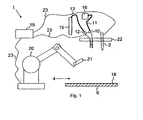
- the welding apparatus 1 according to the invention according to a first embodiment comprises a robot 20 with a changing system 21.
- the changing system 21 is a receptacle at the end of the robot arm for receiving various tools.
- a welding device 2 and a CO 2 nozzle 7 are provided, which are received by the changing system 21 of the robot 10.
- the tools 2, 7 are arranged in a separate magazine 22.
- the welding device 1 comprises a control device 19 for controlling the robot 20, the change system 21 and the tools 2, 7.
- the control device 19 is connected to the robot 20, the change system 21 and the tools 2, 7 via data lines 23.
- the welding device 2 may be formed, for example, as a device for inert gas welding.
- the CO 2 nozzle 7 or gun emits a cryogenic CO 2 compressed air mixture 8 or a cryogenic medium 8.
- the cryogenic medium is a dry ice snow compressed air mixture.
- a compressed air line 11 via a compressed air valve 10 and a CO 2 valve 12, a CO 2 line 13 is connected. Both valves 10, 12 open into a mixing chamber 14 of the CO 2 nozzle 7.
- In the mixing chamber 14 is from liquid CO 2 and / or CO 2 cooling gas and / or CO 2 pellets and / or CO 2 snow and compressed air Cryogenic CO 2 -Pressluft mixture 8 generated.
- the compressed air line 11 is connected to a compressed air supply 16.
- the CO 2 line 13 is connected to a CO 2 storage tank 15.
- a Laval nozzle 17 is arranged.
- the cryogenic CO 2 -Pressluft mixture 8 is accelerated to approximately the speed of sound.
- control device 19 With the control device 19, the formation of the weld 4 and the amount of emitted cryogenic CO 2 -Pressluft mixture can be controlled. With the control device 19, the movements of the robot 20 are controlled.
- the controller 19 controls the entire operation of the welding apparatus 1 by driving the robot 20, the changing system 21, the CO 2 nozzle 7, and the welding apparatus 2 in correspondence.
- the change system 21 of the robot 20 removes the CO 2 nozzle 7 from the magazine 22 and positions it accordingly over a workpiece surface 5 to be cleaned of a workpiece 6.
- the CO 2 valve 12 and the compressed air valve 10 are driven to the CO 2 nozzle 7.
- Compressed air and cryogenic CO 2 flow into the mixing chamber 14 of the CO 2 nozzle 7.
- the cryogenic CO 2 -Pressluft mixture forms 8.
- the cryogenic CO 2 -Pressluft mixture is accelerated when flowing through the Laval nozzle 17 to approximately the speed of sound.
- the cryogenic CO 2 -Pressluft-mixture 8 hits the adhering to a workpiece surface 5 drawing agent 18 and removes this, so that a clean workpiece surface 5 is provided on the a high-quality weld. 3 can be produced.
- the robot 20 moves the CO 2 nozzle 7 in the welding direction. 4
- the robot 20 or the changing system 21 again deposits the CO 2 nozzle 7 in the magazine 22 and removes the welding device 2 from the magazine 22 and positions it over the magazine cleaned and cooled area of the workpiece surface 5.
- the welding device 2 is then driven by the control device 19 and begins with the production of a weld 3 in the welding direction 4 on the workpiece surface 5.
- the workpiece 6 is for example a deep-drawn aluminum component.
- weld 3 is post-treated with the CO 2 nozzle 7 in order to clean them and / or to minimize the delay.
- cryogenic CO 2 compressed air mixture in particular a mixture of liquid CO 2 or CO 2 snow or CO 2 pellets or gaseous CO 2 with compressed air is provided.
- cryogenic medium passes on impact with the surface under atmospheric pressure in the gaseous state, wherein an approximately 600-fold increase in volume of the cryogenic medium takes place. The resulting gas vortices remove the supercooled and embrittled release or drawing agent residue without damaging the workpiece surface.
- the invention has been explained with reference to the joining of metallic workpieces.
- the invention is not limited to the joining of metallic workpieces.
- other materials such as plastics or glass to add and cool in advance by means of a cryogenic medium in the joint seam and clean.
Landscapes
- Engineering & Computer Science (AREA)
- Mechanical Engineering (AREA)
- Physics & Mathematics (AREA)
- Plasma & Fusion (AREA)
- Optics & Photonics (AREA)
- Arc Welding In General (AREA)
- Laser Beam Processing (AREA)
- Cleaning By Liquid Or Steam (AREA)
- Cleaning In General (AREA)
Description
- Die vorliegende Erfindung betrifft eine Vorrichtung und ein Verfahren zum Schweißen von Werkstücken.
- Beim Schweißen werden Bauteile unter Anwendung von Wärme oder Druck mit oder ohne Schweißzusätze unlösbar miteinander verbunden. Schweißverfahren, die mit Wärme arbeiten, sind beispielsweise Feuerschweißen, Gasschmelzschweißen, Lichtbogenhandschweißen, Widerstandsschweißen, Laserstrahlschweißen, aluminothermisches Schweißen und Elektronenstrahlschweißen.
- Mit den bekannten Schweißverfahren können metallische Werkstücke, Kunststoffteile sowie Glassteile miteinander dauerhaft und fest verbunden werden.
- Häufig werden tiefgezogene bzw. hochdruckumgeformte metallische Bauteile mittels Schweißverfahren weiterbearbeitet.
- Beim Tiefziehen wird ein Blechzuschnitt in einen einseitig offenen Hohlkörper oder ein vorgezogener Hohlkörper in einen Hohlkörper mit geringerem Querschnitt und ohne gewollte Veränderung der Blechdicke zugdruckumgeformt.
- Um Ziehfehler, insbesondere das Reißen des Werkstoffs auch bei höheren Umformgraden zu verhindern, werden Ziehmittel, beispielsweise Fette, Öle, Seifen und Überzüge, verwendet. Dadurch werden die Verschleißerscheinungen am Werkzeug vermindert und die Oberflächenbeschaffenheit des Werkstücks verbessert. Diese Ziehmittel hinterlassen nach dem Umformprozess Rückstände auf der Oberfläche. Zum Schweißen der geformten Teile müssen diese von den Ziehmittelrückständen gereinigt werden, da die Ziehmittelsubstanzen eine hochwertige Verschweißung nicht zulassen. Das Entfernen der Ziehmittel durch Waschen oder Beizen ist sehr aufwändig und umweltbelastend, da das gesamte Bauteil gereinigt werden muss.
- Beim Hochdruckumformen kann es passieren, dass die Ziehmittel so tief in die Aluminiumoberfläche eingepresst werden, dass ein vollständiges Entfernen durch Waschen oder Beizen nicht mehr möglich ist. Dies führt bei der weiteren Bearbeitung, beispielsweise beim Fügen durch Schweißen, zu Schweißnahtfehlern.
- Zur Oberflächenreinigung ist das Reinigen mit CO2-Pellets und CO2-Strahl bekannt. Die Temperatur derartiger cryogener Medien beträgt von -50°C bis zu -196°C.
- Aus der
EP 1 356 890 A1 geht ein Teilbearbeitungs- bzw. Schweißverfahren hervor, das durch einen cryogenen Strahl unterstützt wird. Bei dem Verfahren wird eine Schweißeinrichtung verwendet, in deren unmittelbarer Nähe eine oder mehrere Düsen zum Ausgeben eines cryogenen Mediums angeordnet sind. Als cryogenes Medium kann flüssiger Stickstoff oder festes CO2 verwendet werden. Durch das aus der bzw. den Düsen ausströmende cryogene Medium werden sich beim Schweißen bildende flüssige Metallspritzer sehr schnell abgekühlt und verfestigt. Auf diese Weise haften die flüssigen Metallspritzer nicht an der Werkstückoberfläche an und verunreinigen diese nicht. Dadurch ist eine Nachbearbeitung der Werkstücke überflüssig. Da die Schweißspritzer abgekühlt werden sollen, muss das cryogene Medium in unmittelbarer Nachbarschaft zum Lichtbogen zugeführt werden. Dies hat erheblichen Einfluss auf den Lichtbogen und beeinträchtigt den Schweißvorgang erheblich. - In der
EP 1 319 460 A1 ist ein Verfahren zur Schweißvorbereitung von Werkstücken beschrieben. Bei diesem Verfahren ist vorgesehen, die beiden miteinander zu verbindenden Schweißkanten zweier Werkstücke nebeneinander anzuordnen und die Schweißkanten mit einem CO2-Strahl zu bestrahlen, um auf diese Weise Verunreinigungen von der Werkstückoberfläche zu entfernen. - In der
WO 2007/080372 A1 ist eine Vorrichtung zum Kühlen von Werkstücken beim Schweißen beschrieben. Die Vorrichtung weist ein Gehäuse mit einer Düse zum Abstrahlen eines cryogenen Mediums und mit einer Absaugung auf. Das Gehäuse ist mittels einer Dichtung dicht auf eine Werkstückoberfläche aufsetzbar. Hierdurch soll verhindert werden, dass beim Kühlen mittels cryogenem CO2, beim Verdampfen des cryogenen CO2, Gase in die Schweißnaht gelangen und auf diese Weise die Qualität der Schweißnaht beeinflusst wird. Die Vorrichtung kann Verbindungsmittel aufweisen, um mit einer Schweißvorrichtung derart verbunden zu werden, dass sie in Schweißrichtung hinter der Schweißvorrichtung angeordnet ist. Die Befestigungsmittel können derart ausgebildet sein, dass die Position der Vorrichtung bezüglich der Schweißvorrichtung einstellbar ist. Dabei ist vorgesehen, die Vorrichtung etwa 60 bis 90 mm hinter der Schweißvorrichtung anzuordnen. Mit dieser Vorrichtung sollen Verzüge nach dem Schweißvorgang effektiv minimiert werden. Die Vorrichtung soll für jede beliebige Schweißtechnik geeignet sein. - Aufgabe der Erfindung ist es ein Verfahren und eine Vorrichtung bereitzustellen, mit denen es möglich ist, dass Ziehmittelrückstände auf einer Werkstückoberfläche entfernt werden, ohne dass das gesamte Werkstück gereinigt werden muss. Zudem sollen Rückstände entfernt werden, die durch Beizen oder Waschen nicht entfernt werden können.
- Die Aufgabe wird mit einer Vorrichtung mit den Merkmalen des Anspruchs 5 und einem Verfahren mit den Merkmalen des Anspruchs 1 gelöst.
- Vorteilhafte Weiterbildungen sind in den jeweiligen Unteransprüchen angegeben.
- Mit der erfindungsgemäßen Vorrichtung können Werkstückoberflächen dem Schweißvorgang vorauseilend gereinigt und gekühlt werden.
- Beim Beschuss der Werkstückoberfläche mit cryogenem Medium entstehen mehrere vorteilhafte Effekte. Neben dem zunächst erfolgenden mechanischen Abtragen von Trenn- bzw. Ziehmittelrückständen durch Abrasion ergibt sich eine starke punktuelle Abkühlung des bestrahlten Bereiches, woraus sich vorteilhafte Effekte für den nachfolgenden Schweißvorgang ergeben. Der Einzugsbereich der Schweißnaht wird vollständig von Verunreinigungen befreit, wodurch eine optimale Schweißnaht erzeugt werden kann. Durch die Kühlung des Einzugsbereichs der Schweißnaht möglichst unmittelbar vor dem Schweißvorgang, wird die Qualität der Schweißnaht zusätzlich verbessert und der Verzug am Werkstück wird minimiert, wodurch spätere Richtarbeiten reduziert werden bzw. zum Teil völlig entfallen können. Zudem geht das cryogene Medium beim Aufprall auf die Oberfläche unter Atmosphärendruck in den gasförmigen Zustand über, wobei eine ca. 600-fache Volumenvergrößerung des cryogenen Mediums stattfindet. Die dadurch entstehenden Gaswirbel entfernen die unterkühlten und versprödeten Trenn- bzw. Ziehmittelrückstände, ohne die Werkstückoberfläche zu beschädigen.
- Die erfindungsgemässe Schweißvorrichtung ist vor allem zum Schweißen von metallischen Werkstücken ausgebildet. Im Rahmen der vorliegenden Erfindung ist es jedoch möglich, Schweißeinrichtungen zum Schweißen von Werkstücken aus Kunststoff oder Glas vorzusehen. Auch diese Werkstücke können mit einem cryogenen Medium gereinigt werden. Bei Kunstoffen können vor allem Trennmittel und Spritzhäute von spritzgegossenen Kunststoffteilen entfernt werden. Geeignete Schweißverfahren zum Schweißen von Kunststoffen sind Warmgasschweißen, Heizelementschweißen, Reibschweißen, Ultraschallschweißen, Hochfrequenzschweißen und Laserschweißen.
- Die Erfindung wird beispielhaft anhand der Zeichnung erläutert. Es zeigt dabei schematisch:
- Fig. 1
- ein erstes Ausführungsbeispiel einer Schweißvorrichtung mit einem Roboter zum Handhaben einer Schweißeinrichtung und einer CO2-Düse
- Die erfindungsgemäße Schweißvorrichtung 1 gemäß einem ersten Ausführungsbeispiel umfasst einen Roboter 20 mit einem Wechselsystem 21. Das Wechselsystem 21 ist eine Aufnahme am Ende des Roboterarms, um verschiedene Werkzeuge aufzunehmen. Als Werkzeuge sind eine Schweißeinrichtung 2 und eine CO2-Düse 7 vorgesehen, die vom Wechselsystem 21 des Roboters 10 aufgenommen werden. Die Werkzeuge 2, 7 sind in einem separaten Magazin 22 angeordnet.
- Die Schweißvorrichtung 1 umfasst eine Steuereinrichtung 19 zur Ansteuerung des Roboters 20, des Wechselsystems 21 und der Werkzeuge 2, 7. Die Steuereinrichtung 19 ist mit dem Roboter 20, dem Wechselsystem 21 und den Werkzeugen 2, 7 über Datenleitungen 23 verbunden.
- Die Schweißeinrichtung 2 kann beispielsweise als Einrichtung zum Schutzgasschweißen ausgebildet sein.
- Die CO2-Düse 7 bzw. Pistole gibt ein cryogenes CO2-Pressluft-Gemisch 8 bzw. ein cryogenes Medium 8 aus. Insbesondere ist das cryogene Medium ein Trockeneisschnee-Pressluft-Gemisch. An der CO2-Düse 7 ist über ein Pressluftventil 10 eine Pressluftleitung 11 und über ein CO2-Ventil 12 eine CO2-Leitung 13 angeschlossen. Beide Ventile 10, 12 münden in eine Mischkammer 14 der CO2-Düse 7. In der Mischkammer 14 wird aus flüssigen CO2 und/oder CO2-Kaltgas und/oder CO2-Pellets und/oder CO2-Schnee und Pressluft ein cryogenes CO2-Pressluft-Gemisch 8 erzeugt.
- Die Pressluftleitung 11 ist mit einer Pressluftversorgung 16 verbunden. Die CO2-Leitung 13 ist an einen CO2-Vorratsbehälter 15 angeschlossen.
- Nach der Mischkammer 14 ist eine Lavaldüse 17 angeordnet. Mittels der Lavaldüse 17 wird das cryogene CO2-Pressluft-Gemisch 8 auf annähernd Schallgeschwindigkeit beschleunigt.
- Mit der Steuereinrichtung 19 kann die Ausbildung der Schweißnaht 4 und die Menge an ausgegebenem cryogenem CO2-Pressluft-Gemisch gesteuert werden. Mit der Steuereinrichtung 19 werden die Bewegungen des Roboters 20 gesteuert.
- Nachfolgend wird die Anwendung der oben beschriebenen Vorrichtung 1 beschrieben.
- Die Steuereinrichtung 19 steuert den gesamten Arbeitsablauf der Schweißvorrichtung 1, indem sie entsprechend den Roboter 20, das Wechselsystem 21, die CO2-Düse 7 und die Schweißeinrichtung 2 ansteuert.
- Das Wechselsystem 21 des Roboters 20 entnimmt die CO2-Düse 7 aus dem Magazin 22 und positioniert sie entsprechend über einer zu reinigenden Werkstücksoberfläche 5 eines Werkstücks 6.
- Über die Steuereinrichtung 19 werden das CO2-Ventil 12 und das Pressluftventil 10 an der CO2-Düse 7 angesteuert. Pressluft und cryogenes CO2 strömen in die Mischkammer 14 der CO2-Düse 7 ein. In der Mischkammer 14 bildet sich das cryogene CO2-Pressluft-Gemisch 8. Das cryogene CO2-Pressluft-Gemisch wird beim Durchströmen der Lavaldüse 17 auf annähernd Schallgeschwindigkeit beschleunigt.
- Beim Austritt aus der Lavaldüse 17 bzw. der CO2-Düse 7 trifft das cryogene CO2-Pressluft-Gemisch 8 auf das an einer Werkstückoberfläche 5 anhaftende Ziehmittel 18 und entfernt dieses, sodass eine saubere Werkstückoberfläche 5 bereitgestellt wird auf der eine hochwertige Schweißnaht 3 hergestellt werden kann. Der Roboter 20 verfährt die CO2-Düse 7 in Schweißrichtung 4.
- Zudem wird der Bereich in dem die Schweißnaht 3 ausgebildet wird abgekühlt, was zu einem geringeren Verzug des Werkstücks 6 führt.
- Wenn der gesamte zu reinigende Bereich gereinigt wurde, legt der Roboter 20 bzw. das Wechselsystem 21 die CO2-Düse 7 wieder im Magazin 22 ab und entnimmt die Schweißeinrichtung 2 aus dem Magazin 22 und positioniert diese über dem gereinigten und gekühlten Bereich der Werkstückoberfläche 5. Die Schweißeinrichtung 2 wird dann von der Steuereinrichtung 19 angesteuert und beginnt mit der Herstellung einer Schweißnaht 3 in Schweißrichtung 4 auf der Werkstückoberfläche 5. Das Werkstück 6 ist beispielsweise ein tiefgezogenes Aluminiumbauteil.
- Weiterhin wird die Schweißnaht 3 mit der CO2-Düse 7 nachbehandelt, um diese zu reinigen und/oder den Verzug zu minimieren.
- Insbesondere beim Schweißen von Aluminium ist das Herstellen sauberer Schweißnähte und eine Nachreinigung wichtig, da die Schweißnähte oft Sichtnähte sind, die nicht nachgearbeitet, d.h. poliert oder lackiert werden müssen.
- Als cryogenes CO2-Pressluft-Gemisch ist insbesondere eine Mischung aus flüssigem CO2 oder CO2-Schnee oder CO2-Pelletts oder gasförmigem CO2 mit Pressluft vorgesehen.
- Bei dem Schweißvorgang vorauseilenden Beschuss mit cryogenem Medium entstehen mehrere vorteilhafte Effekte. Neben dem zunächst erfolgenden mechanischen Abtragen von Trenn- bzw. Ziehmittelrückständen durch Abrasion ergibt sich eine starke punktuelle Abkühlung des bestrahlten Bereiches unmittelbar vor dem Schweißvorgang. Der Einzugsbereich der Schweißnaht wird vollständig von Verunreinigungen befreit, wodurch eine optimale Schweißnaht erzeugt werden kann. Durch die Kühlung des Einzugsbereichs der Schweißnaht werden die Verzüge am Werkstück minimiert, wodurch spätere Richtarbeiten zum Teil völlig entfallen können. Zudem geht das cryogene Medium beim Aufprall auf die Oberfläche unter Atmosphärendruck in den gasförmigen Zustand über, wobei eine ca. 600-fache Volumenvergrößerung des cryogenen Mediums stattfindet. Die dadurch entstehenden Gaswirbel entfernen die unterkühlten und versprödeten Trenn- bzw. Ziehmittelrückstände, ohne die Werkstückoberfläche zu beschädigen.
- Oben ist die Erfindung anhand des Fügens von metallischen Werkstücken erläutert worden. Die Erfindung ist jedoch nicht auf das Fügen von metallischen Werkstücken beschränkt. Im Rahmen der Erfindung ist es auch möglich andere Materialien, wie z. B. Kunststoffe oder Glas zu fügen und vorab mittels eines cryogenen Mediums im Bereich der Fügenaht zu kühlen und zu reinigen.
-
- 1
- Schweißvorrichtung
- 2
- Schweißeinrichtung
- 3
- Schweißnaht
- 4
- Schweißrichtung
- 5
- Werkstückoberfläche
- 6
- Werkstück
- 7
- CO2-Düse
- 8
- cryogenes CO2-Pressluft-Gemisch
- 9
- Verbindungselement
- 10
- Pressluftventil
- 11
- Pressluftleitung
- 12
- CO2-Ventil
- 13
- CO2-Leitung
- 14
- Mischkammer
- 15
- CO2-Vorratsbehälter
- 16
- Pressluftversorgung
- 17
- Lavaldüse
- 18
- Ziehmittel
- 19
- Steuereinrichtung
- 20
- Roboter
- 21
- Wechselsystem
- 22
- Magazin
- 23
- Datenleitung
Claims (8)
- Verfahren zum Schweißen von Werkstücken, wobei die Werkstücke (6) mit einem cryogenen Medium (8) auf ihren Oberflächen (5) im Bereich ihrer auszubildenden Schweißnaht bestrahlt werden, um diesen Bereich zu reinigen und zu kühlen, und die Werkstücke in dem gereinigten Bereich miteinander verschweißt werden
dadurch gekennzeichnet,
dass ein Wechselsystem (21) eines Roboters (20) eine CO2-Düse (7) aus einem Magazin (22) entnimmt und damit die Oberfläche eines Werkstückes im Bereich der auszubildenden Schweißnaht mittels des cryogenen Mediums (8) bestrahlt, wobei der Roboter (20) anschließend die CO2-Düse (7) wieder im Magazin (22) ablegt und eine Schweißeinrichtung (2) aus dem Magazin (22) entnimmt und damit dann eine Schweißnaht (3) in Schweißrichtung (4) auf der Werkstückoberfläche (5) erzeugt, wobei die Schweißnaht (3) mit der CO2-Düse (7) nachbehandelt wird, um diese zu reinigen und/oder den Verzug zu minimieren. - Verfahren nach Anspruch 1,
dadurch gekennzeichnet,
dass als cryogenes Medium (8) ein cryogenes CO2-Pressluft-Gemisch abgestrahlt wird. - Verfahren nach Anspruch 2,
dadurch gekennzeichnet,
dass im cryogenen CO2-Pressluft-Gemisch (8) flüssiges CO2 oder CO2-Schnee oder CO2-Pellets oder gasförmiges CO2 verwendet wird. - Verfahren nach einem der Ansprüche 1 bis 3,
dadurch gekennzeichnet,
dass metallische, tiefgezogene Bauteile geschweißt werden, wobei die Bauteile durch das cryogene Medium von Ziehmittelrückständen gereinigt werden. - Schweißvorrichtung zum Ausführen des Verfahrens nach Anspruch 1, mit einer Schweißeinrichtung (2) zum Erzeugen einer Schweißnaht (3) auf Werkstücken (6) und einer CO2-Düse (7), um ein cryogenes Medium (8) auf die Oberflächen (5) der Werkstücke (6) im Bereich ihrer auszubildenden Schweißnaht abzustrahlen, dadurch gekennzeichnet dass die Schweißvorrichtung (1) umfasst
einen Roboter (20) mit einem Wechselsystem (21),
wobei das Wechselsystem (21) am Ende eines Roboterarms des Roboters (20) angeordnet ist und als Aufnahme (21) zum Aufnehmen der Schweißeinrichtung (2) und der CO2-Düse (7) ausgebildet ist,
wobei die Schweißeinrichtung (2) und die CO2-Düse (7) in einem Magazin (22) angeordnet sind, und
eine Steuereinrichtung (19) zur Ansteuerung des Roboters (20), des Wechselsystems (21), der Schweißeinrichtung (2) und der CO2-Düse (7) die derart ausgebildet ist,
dass der Bereich der auszubildenden Schweißnaht mittels der CO2-Düse (7) bestrahlt und nachfolgend mittels der Schweißeinrichtung (2) verschweißt wird, wobei die Schweißnaht (3) mit der CO2-Düse (7) nachbehandelt wird, um diese zu reinigen und/oder den Verzug zu minimieren. - Schweißvorrichtung gemäß Anspruch 5,
dadurch gekennzeichnet,
dass die CO2-Düse (7) eine Mischkammer (14) aufweist, die zum Erzeugen eines cryogenen CO2-Pressluft-Gemisches (8) aus flüssigen CO2 und/oder CO2-Kaltgas und/oder CO2-Pellets und/oder CO2-Schnee und Pressluft ausgebildet ist. - Schweißvorrichtung nach Anspruch 5 oder 6,
dadurch gekennzeichnet,
dass die Schweißeinrichtung (2) als Einrichtung zum Gasschmelzschweißen, Lichtbogenhandschweißen oder Laserstrahlschweißen ausgebildet ist. - Schweißvorrichtung nach einem der Ansprüche 5 bis 7,
dadurch gekennzeichnet,
dass die Steuereinrichtung (19) zum Ausführen eines Verfahrens nach einem der Ansprüche 1 bis 4 ausgebildet ist.
Priority Applications (1)
| Application Number | Priority Date | Filing Date | Title |
|---|---|---|---|
| EP08012421A EP2014401B1 (de) | 2007-07-10 | 2008-07-09 | Vorrichtung und Verfahren zum Schweißen von Werkstücken |
Applications Claiming Priority (3)
| Application Number | Priority Date | Filing Date | Title |
|---|---|---|---|
| DE102007032067A DE102007032067A1 (de) | 2007-07-10 | 2007-07-10 | Vorrichtung und Verfahren zur CO2 Reinigung beim Schweißen von Metallen |
| EP07022615A EP2014400A1 (de) | 2007-07-10 | 2007-11-21 | Vorrichtung und Verfahren zum Schweissen von metallischen Werkstücken |
| EP08012421A EP2014401B1 (de) | 2007-07-10 | 2008-07-09 | Vorrichtung und Verfahren zum Schweißen von Werkstücken |
Publications (2)
| Publication Number | Publication Date |
|---|---|
| EP2014401A1 EP2014401A1 (de) | 2009-01-14 |
| EP2014401B1 true EP2014401B1 (de) | 2012-06-27 |
Family
ID=39047807
Family Applications (2)
| Application Number | Title | Priority Date | Filing Date |
|---|---|---|---|
| EP07022615A Withdrawn EP2014400A1 (de) | 2007-07-10 | 2007-11-21 | Vorrichtung und Verfahren zum Schweissen von metallischen Werkstücken |
| EP08012421A Not-in-force EP2014401B1 (de) | 2007-07-10 | 2008-07-09 | Vorrichtung und Verfahren zum Schweißen von Werkstücken |
Family Applications Before (1)
| Application Number | Title | Priority Date | Filing Date |
|---|---|---|---|
| EP07022615A Withdrawn EP2014400A1 (de) | 2007-07-10 | 2007-11-21 | Vorrichtung und Verfahren zum Schweissen von metallischen Werkstücken |
Country Status (5)
| Country | Link |
|---|---|
| US (1) | US20090014422A1 (de) |
| EP (2) | EP2014400A1 (de) |
| JP (1) | JP5348957B2 (de) |
| DE (1) | DE102007032067A1 (de) |
| ES (1) | ES2389226T3 (de) |
Families Citing this family (27)
| Publication number | Priority date | Publication date | Assignee | Title |
|---|---|---|---|---|
| DE102008033797A1 (de) | 2008-07-18 | 2010-01-21 | Linde Ag | Vorrichtung und Verfahren zum thermischen Verbinden und/oder Trennen von metallischen Werkstücken |
| DE102010026717A1 (de) * | 2010-07-09 | 2011-07-28 | KAUTEX TEXTRON GmbH & Co. KG, 53229 | Verfahren zur Herstellung von Hohlkörpern aus thermoplastischem Kunststoff sowie Vorrichtung zum Durchführen des Verfahrens |
| MX2013007507A (es) * | 2010-12-30 | 2013-11-04 | Bosch Gmbh Robert | Metodo y dispositivo para procesar un anillo de metal, una banda de metal anular asi formada y una banda de transmision en la cual se utiliza la banda de metal anular. |
| EP2591871A1 (de) * | 2011-11-10 | 2013-05-15 | Air Liquide Deutschland GmbH | Verfahren und Vorrichtung zum Abkühlen von gelöteten Flachbaugruppen |
| EP2586558A1 (de) * | 2011-10-25 | 2013-05-01 | Air Liquide Deutschland GmbH | Verfahren und Vorrichtung zum Abkühlen von gelöteten Flachbaugruppen |
| MX346505B (es) | 2011-10-25 | 2017-03-22 | Air Liquide | Método y dispositivo para enfriar tableros de circuitos impresos soldados. |
| US20130105561A1 (en) * | 2011-11-01 | 2013-05-02 | Amee Bay, Llc | Dry ice cleaning of metal surfaces to improve welding characteristics |
| GB201204752D0 (en) * | 2012-03-19 | 2012-05-02 | Bae Systems Plc | Additive layer manufacturing |
| DE102012015121A1 (de) | 2012-08-01 | 2014-05-15 | Newfrey Llc | Bolzenfügeverfahren und -vorrichtung |
| CN103433616B (zh) * | 2013-07-25 | 2016-02-03 | 中国科学院理化技术研究所 | 一种搅拌摩擦焊装置 |
| GB2527375A (en) * | 2014-06-20 | 2015-12-23 | Linde Ag | Welding apparatus |
| US9880144B2 (en) | 2014-12-19 | 2018-01-30 | Palo Alto Research Center Incorporated | Electrochemical metal and alloy detector and method |
| US9797857B2 (en) * | 2015-02-19 | 2017-10-24 | Palo Alto Research Center Incorporated | Systems for electrochemical sorting of metals and alloys |
| US9702845B2 (en) | 2015-02-19 | 2017-07-11 | Palo Alto Research Center Incorporated | Systems for electrochemical sorting of metals and alloys |
| US10794858B2 (en) | 2016-08-15 | 2020-10-06 | Palo Alto Research Center Incorporated | Alloy identification device |
| DE102016117177A1 (de) * | 2016-09-13 | 2018-03-15 | Newfrey Llc | Verfahren und Vorrichtung zum Fügen eines Fügeelementes auf einem Werkstück |
| DE102016125599A1 (de) * | 2016-12-23 | 2018-06-28 | Newfrey Llc | Verfahren und Vorrichtung zum Fügen von Fügeelementen auf Bauteile |
| CN108655542B (zh) * | 2018-05-23 | 2020-06-19 | 宁波家禾节能科技有限公司 | 一种锅炉筒体智能焊接同步探伤检测装置 |
| KR102102763B1 (ko) * | 2018-12-27 | 2020-04-22 | 주식회사 세원정공 | 카울 크로스 부품 용접 시스템 |
| CN109702498B (zh) * | 2019-03-01 | 2021-02-26 | 江苏省特种设备安全监督检验研究院 | 一种基于高压水射流技术的焊接强化装置 |
| EP3741489A1 (de) * | 2019-05-24 | 2020-11-25 | Linde GmbH | Vorrichtung zur reinigung und kühlung eines werkstücks während der generativen drahtlichtbogenfertigung (waam) |
| DE102020003866A1 (de) * | 2020-06-27 | 2021-12-30 | Linde Gmbh | Vorrichtung und Verfahren zum Kühlen von Bauteilen, insbesondere beim Schutzgasschweißen oder beim Generativen Fertigen mittels Schutzgasschweißen, mit einem CO2-Partikelstrahl |
| US11660700B2 (en) | 2021-06-04 | 2023-05-30 | Dus Operating Inc. | Welding and deburring system with cryogenic cooling |
| DE102021005854A1 (de) | 2021-11-25 | 2023-05-25 | Messer Se & Co. Kgaa | Verfahren zur Reduzierung des Verzugs beim Schweißen und Schneiden von Metallen |
| CN114345839B (zh) * | 2021-12-28 | 2023-04-11 | 北京航星机器制造有限公司 | 一种钛合金筒体纵缝的清洗方法及系统 |
| CN119368987B (zh) * | 2024-12-27 | 2025-03-21 | 浙江劳士顿科技股份有限公司 | 一种电焊机的冷却装置及其使用方法 |
| CN120962355A (zh) * | 2025-10-20 | 2025-11-18 | 湖南科技大学 | 一种智能焊磨一体化制造系统及其加工方法 |
Family Cites Families (12)
| Publication number | Priority date | Publication date | Assignee | Title |
|---|---|---|---|---|
| US3084246A (en) * | 1959-07-06 | 1963-04-02 | Exxon Research Engineering Co | Process and apparatus for welding |
| JPH0252173A (ja) * | 1988-08-12 | 1990-02-21 | Mitsubishi Heavy Ind Ltd | 入熱制御溶接方法 |
| JPH0335893A (ja) * | 1989-07-03 | 1991-02-15 | Amada Co Ltd | 溶接変形を低減する溶接方法とその溶接方法に用いる溶接トーチ |
| US5599223A (en) * | 1991-04-10 | 1997-02-04 | Mains Jr.; Gilbert L. | Method for material removal |
| JP3627194B2 (ja) * | 1994-11-30 | 2005-03-09 | 株式会社石井鐵工所 | オーステナイト系ステンレス鋼の溶接法 |
| DE19953230C2 (de) * | 1999-11-04 | 2003-08-28 | C D Waelzholz Produktionsgmbh | Kaltwalzverfahren |
| GB0010793D0 (en) * | 2000-05-03 | 2000-06-28 | Boc Group Plc | Improvements in thermal welding |
| GB0129353D0 (en) | 2001-12-07 | 2002-01-30 | Boc Group Plc | Weld preparation method |
| GB0209380D0 (en) * | 2002-04-24 | 2002-06-05 | Boc Group Plc | Metal working |
| US7513121B2 (en) * | 2004-03-25 | 2009-04-07 | Air Products And Chemicals, Inc. | Apparatus and method for improving work surface during forming and shaping of materials |
| EP1991390A1 (de) * | 2006-01-11 | 2008-11-19 | BAE Systems PLC | Verbesserungen bei kältemittelzufuhr |
| JP2007237228A (ja) * | 2006-03-08 | 2007-09-20 | Taiyo Nippon Sanso Corp | アーク溶接装置及びアーク溶接方法 |
-
2007
- 2007-07-10 DE DE102007032067A patent/DE102007032067A1/de not_active Withdrawn
- 2007-11-21 EP EP07022615A patent/EP2014400A1/de not_active Withdrawn
-
2008
- 2008-07-09 EP EP08012421A patent/EP2014401B1/de not_active Not-in-force
- 2008-07-09 ES ES08012421T patent/ES2389226T3/es active Active
- 2008-07-10 JP JP2008180331A patent/JP5348957B2/ja not_active Expired - Fee Related
- 2008-07-10 US US12/171,114 patent/US20090014422A1/en not_active Abandoned
Also Published As
| Publication number | Publication date |
|---|---|
| US20090014422A1 (en) | 2009-01-15 |
| JP5348957B2 (ja) | 2013-11-20 |
| JP2009018346A (ja) | 2009-01-29 |
| DE102007032067A1 (de) | 2009-01-15 |
| EP2014400A1 (de) | 2009-01-14 |
| ES2389226T3 (es) | 2012-10-24 |
| EP2014401A1 (de) | 2009-01-14 |
Similar Documents
| Publication | Publication Date | Title |
|---|---|---|
| EP2014401B1 (de) | Vorrichtung und Verfahren zum Schweißen von Werkstücken | |
| DE102007052945B3 (de) | Laserbearbeitungsmaschine | |
| DE69232469T2 (de) | Bodenflächenstrahlgerät | |
| WO2009092760A1 (de) | Verfahren und vorrichtung zum abtragen einer metallischen beschichtung | |
| EP1454700B1 (de) | Kühl- und/oder Spüllanze einer Laserbearbeitungsmaschine und Verfahren zum Absaugen von Partikeln, Gasen oder Dämpfen bei einer Laserbearbeitung | |
| DE102007026333A1 (de) | System und Verfahren zum Verringern von Schweißspritzern | |
| DE19525989A1 (de) | Lochformverfahren und Lochvorrichtung | |
| EP1732713B1 (de) | Reinigungsvorrichtung zum reinigen von schweissbrennern | |
| DE102016204341A1 (de) | Sprühstation für Schweißtrennmittel und Verfahren zum automatisierten Besprühen | |
| EP1987944A1 (de) | Laserdurchstrahlschweissvorrichtung und Verfahren zum Verbinden von Kunststoffwerkstücken | |
| DE60224977T2 (de) | Schweissvorbereitungsverfahren | |
| EP3359337B1 (de) | Verfahren zum reinigen von klebeflächen mithilfe von festen kohlenstoffdioxid | |
| EP3359336B1 (de) | Verfahren zum reinigen mithilfe von festem kohlenstoffdioxid | |
| DE102004063473B4 (de) | Verfahren und Vorrichtung zum Reinigen von Schweißbrennern | |
| EP1784275A1 (de) | Verfahren und vorrichtung zum reinigen von schweissbrennern mit co2-trockeneis | |
| DE102020003866A1 (de) | Vorrichtung und Verfahren zum Kühlen von Bauteilen, insbesondere beim Schutzgasschweißen oder beim Generativen Fertigen mittels Schutzgasschweißen, mit einem CO2-Partikelstrahl | |
| WO2009152807A1 (de) | Verfahren und vorrichtung zum induktiven reinigen und entschichten einer metallischen werkstücksoberfläche | |
| DE19949445C1 (de) | Verfahren zur Versorgung einer Werkzeugform mit einem Fertigungshilfsmittel | |
| DE3543910C2 (de) | Verfahren zum Entgraten von Formteilen | |
| WO2001023112A1 (de) | Vorrichtung und verfahren zum kälteunterstützten mechanischen entfernen von oberflächenbeschichtungen | |
| DE112018007882T5 (de) | Ölentfernungsverfahren, Verbindungsverfahren, Montagevorrichtung und Atmosphärendruck-Plasmavorrichtung | |
| EP1039976B1 (de) | Vorrichtung zur regenerierung lackierter und/oder grundierter bleche | |
| DE102005022502B3 (de) | Vorrichtung und Verfahren zum Entfernen von harten Schweißschlacken | |
| DE3105836A1 (de) | "verfahren und vorrichtung zur entfernung von ueberschuessigen klebern von den boerdelkanten von werkstuecken" | |
| EP0593971A2 (de) | Verfahren zum Entfernen von Spänen aus Werkstücken |
Legal Events
| Date | Code | Title | Description |
|---|---|---|---|
| PUAI | Public reference made under article 153(3) epc to a published international application that has entered the european phase |
Free format text: ORIGINAL CODE: 0009012 |
|
| AK | Designated contracting states |
Kind code of ref document: A1 Designated state(s): AT BE BG CH CY CZ DE DK EE ES FI FR GB GR HR HU IE IS IT LI LT LU LV MC MT NL NO PL PT RO SE SI SK TR |
|
| AX | Request for extension of the european patent |
Extension state: AL BA MK RS |
|
| RAP1 | Party data changed (applicant data changed or rights of an application transferred) |
Owner name: LINDE AG |
|
| AKX | Designation fees paid | ||
| RBV | Designated contracting states (corrected) |
Designated state(s): AT BE BG CH CY CZ DE DK EE ES FI FR GB GR HR HU IE IS IT LI LT LU LV MC MT NL NO PL PT RO SE SI SK TR |
|
| 17P | Request for examination filed |
Effective date: 20090714 |
|
| 17Q | First examination report despatched |
Effective date: 20091026 |
|
| 17Q | First examination report despatched |
Effective date: 20101104 |
|
| GRAP | Despatch of communication of intention to grant a patent |
Free format text: ORIGINAL CODE: EPIDOSNIGR1 |
|
| GRAS | Grant fee paid |
Free format text: ORIGINAL CODE: EPIDOSNIGR3 |
|
| GRAA | (expected) grant |
Free format text: ORIGINAL CODE: 0009210 |
|
| AK | Designated contracting states |
Kind code of ref document: B1 Designated state(s): AT BE BG CH CY CZ DE DK EE ES FI FR GB GR HR HU IE IS IT LI LT LU LV MC MT NL NO PL PT RO SE SI SK TR |
|
| REG | Reference to a national code |
Ref country code: GB Ref legal event code: FG4D Free format text: NOT ENGLISH |
|
| REG | Reference to a national code |
Ref country code: CH Ref legal event code: EP |
|
| REG | Reference to a national code |
Ref country code: AT Ref legal event code: REF Ref document number: 563882 Country of ref document: AT Kind code of ref document: T Effective date: 20120715 |
|
| REG | Reference to a national code |
Ref country code: IE Ref legal event code: FG4D Free format text: LANGUAGE OF EP DOCUMENT: GERMAN |
|
| REG | Reference to a national code |
Ref country code: DE Ref legal event code: R096 Ref document number: 502008007542 Country of ref document: DE Effective date: 20120823 |
|
| REG | Reference to a national code |
Ref country code: ES Ref legal event code: FG2A Ref document number: 2389226 Country of ref document: ES Kind code of ref document: T3 Effective date: 20121024 |
|
| PG25 | Lapsed in a contracting state [announced via postgrant information from national office to epo] |
Ref country code: FI Free format text: LAPSE BECAUSE OF FAILURE TO SUBMIT A TRANSLATION OF THE DESCRIPTION OR TO PAY THE FEE WITHIN THE PRESCRIBED TIME-LIMIT Effective date: 20120627 Ref country code: SE Free format text: LAPSE BECAUSE OF FAILURE TO SUBMIT A TRANSLATION OF THE DESCRIPTION OR TO PAY THE FEE WITHIN THE PRESCRIBED TIME-LIMIT Effective date: 20120627 Ref country code: LT Free format text: LAPSE BECAUSE OF FAILURE TO SUBMIT A TRANSLATION OF THE DESCRIPTION OR TO PAY THE FEE WITHIN THE PRESCRIBED TIME-LIMIT Effective date: 20120627 Ref country code: NO Free format text: LAPSE BECAUSE OF FAILURE TO SUBMIT A TRANSLATION OF THE DESCRIPTION OR TO PAY THE FEE WITHIN THE PRESCRIBED TIME-LIMIT Effective date: 20120927 |
|
| REG | Reference to a national code |
Ref country code: SK Ref legal event code: T3 Ref document number: E 12288 Country of ref document: SK |
|
| REG | Reference to a national code |
Ref country code: NL Ref legal event code: VDEP Effective date: 20120627 |
|
| REG | Reference to a national code |
Ref country code: LT Ref legal event code: MG4D Effective date: 20120627 |
|
| PG25 | Lapsed in a contracting state [announced via postgrant information from national office to epo] |
Ref country code: SI Free format text: LAPSE BECAUSE OF FAILURE TO SUBMIT A TRANSLATION OF THE DESCRIPTION OR TO PAY THE FEE WITHIN THE PRESCRIBED TIME-LIMIT Effective date: 20120627 Ref country code: LV Free format text: LAPSE BECAUSE OF FAILURE TO SUBMIT A TRANSLATION OF THE DESCRIPTION OR TO PAY THE FEE WITHIN THE PRESCRIBED TIME-LIMIT Effective date: 20120627 Ref country code: GR Free format text: LAPSE BECAUSE OF FAILURE TO SUBMIT A TRANSLATION OF THE DESCRIPTION OR TO PAY THE FEE WITHIN THE PRESCRIBED TIME-LIMIT Effective date: 20120928 Ref country code: HR Free format text: LAPSE BECAUSE OF FAILURE TO SUBMIT A TRANSLATION OF THE DESCRIPTION OR TO PAY THE FEE WITHIN THE PRESCRIBED TIME-LIMIT Effective date: 20120627 |
|
| BERE | Be: lapsed |
Owner name: LINDE A.G. Effective date: 20120731 |
|
| PG25 | Lapsed in a contracting state [announced via postgrant information from national office to epo] |
Ref country code: CY Free format text: LAPSE BECAUSE OF FAILURE TO SUBMIT A TRANSLATION OF THE DESCRIPTION OR TO PAY THE FEE WITHIN THE PRESCRIBED TIME-LIMIT Effective date: 20120627 Ref country code: RO Free format text: LAPSE BECAUSE OF FAILURE TO SUBMIT A TRANSLATION OF THE DESCRIPTION OR TO PAY THE FEE WITHIN THE PRESCRIBED TIME-LIMIT Effective date: 20120627 Ref country code: EE Free format text: LAPSE BECAUSE OF FAILURE TO SUBMIT A TRANSLATION OF THE DESCRIPTION OR TO PAY THE FEE WITHIN THE PRESCRIBED TIME-LIMIT Effective date: 20120627 Ref country code: IS Free format text: LAPSE BECAUSE OF FAILURE TO SUBMIT A TRANSLATION OF THE DESCRIPTION OR TO PAY THE FEE WITHIN THE PRESCRIBED TIME-LIMIT Effective date: 20121027 |
|
| PG25 | Lapsed in a contracting state [announced via postgrant information from national office to epo] |
Ref country code: MC Free format text: LAPSE BECAUSE OF NON-PAYMENT OF DUE FEES Effective date: 20120731 Ref country code: PT Free format text: LAPSE BECAUSE OF FAILURE TO SUBMIT A TRANSLATION OF THE DESCRIPTION OR TO PAY THE FEE WITHIN THE PRESCRIBED TIME-LIMIT Effective date: 20121029 Ref country code: PL Free format text: LAPSE BECAUSE OF FAILURE TO SUBMIT A TRANSLATION OF THE DESCRIPTION OR TO PAY THE FEE WITHIN THE PRESCRIBED TIME-LIMIT Effective date: 20120627 |
|
| REG | Reference to a national code |
Ref country code: CH Ref legal event code: PL |
|
| PG25 | Lapsed in a contracting state [announced via postgrant information from national office to epo] |
Ref country code: NL Free format text: LAPSE BECAUSE OF FAILURE TO SUBMIT A TRANSLATION OF THE DESCRIPTION OR TO PAY THE FEE WITHIN THE PRESCRIBED TIME-LIMIT Effective date: 20120627 |
|
| PG25 | Lapsed in a contracting state [announced via postgrant information from national office to epo] |
Ref country code: DK Free format text: LAPSE BECAUSE OF FAILURE TO SUBMIT A TRANSLATION OF THE DESCRIPTION OR TO PAY THE FEE WITHIN THE PRESCRIBED TIME-LIMIT Effective date: 20120627 Ref country code: LI Free format text: LAPSE BECAUSE OF NON-PAYMENT OF DUE FEES Effective date: 20120731 Ref country code: CH Free format text: LAPSE BECAUSE OF NON-PAYMENT OF DUE FEES Effective date: 20120731 |
|
| PLBE | No opposition filed within time limit |
Free format text: ORIGINAL CODE: 0009261 |
|
| STAA | Information on the status of an ep patent application or granted ep patent |
Free format text: STATUS: NO OPPOSITION FILED WITHIN TIME LIMIT |
|
| REG | Reference to a national code |
Ref country code: IE Ref legal event code: MM4A |
|
| PG25 | Lapsed in a contracting state [announced via postgrant information from national office to epo] |
Ref country code: BE Free format text: LAPSE BECAUSE OF NON-PAYMENT OF DUE FEES Effective date: 20120731 |
|
| 26N | No opposition filed |
Effective date: 20130328 |
|
| REG | Reference to a national code |
Ref country code: DE Ref legal event code: R097 Ref document number: 502008007542 Country of ref document: DE Effective date: 20130328 |
|
| PG25 | Lapsed in a contracting state [announced via postgrant information from national office to epo] |
Ref country code: BG Free format text: LAPSE BECAUSE OF FAILURE TO SUBMIT A TRANSLATION OF THE DESCRIPTION OR TO PAY THE FEE WITHIN THE PRESCRIBED TIME-LIMIT Effective date: 20120927 Ref country code: IE Free format text: LAPSE BECAUSE OF NON-PAYMENT OF DUE FEES Effective date: 20120709 Ref country code: MT Free format text: LAPSE BECAUSE OF FAILURE TO SUBMIT A TRANSLATION OF THE DESCRIPTION OR TO PAY THE FEE WITHIN THE PRESCRIBED TIME-LIMIT Effective date: 20120627 |
|
| PG25 | Lapsed in a contracting state [announced via postgrant information from national office to epo] |
Ref country code: TR Free format text: LAPSE BECAUSE OF FAILURE TO SUBMIT A TRANSLATION OF THE DESCRIPTION OR TO PAY THE FEE WITHIN THE PRESCRIBED TIME-LIMIT Effective date: 20120627 |
|
| PG25 | Lapsed in a contracting state [announced via postgrant information from national office to epo] |
Ref country code: LU Free format text: LAPSE BECAUSE OF NON-PAYMENT OF DUE FEES Effective date: 20120709 |
|
| PG25 | Lapsed in a contracting state [announced via postgrant information from national office to epo] |
Ref country code: HU Free format text: LAPSE BECAUSE OF FAILURE TO SUBMIT A TRANSLATION OF THE DESCRIPTION OR TO PAY THE FEE WITHIN THE PRESCRIBED TIME-LIMIT Effective date: 20080709 |
|
| REG | Reference to a national code |
Ref country code: AT Ref legal event code: MM01 Ref document number: 563882 Country of ref document: AT Kind code of ref document: T Effective date: 20130709 |
|
| PG25 | Lapsed in a contracting state [announced via postgrant information from national office to epo] |
Ref country code: AT Free format text: LAPSE BECAUSE OF NON-PAYMENT OF DUE FEES Effective date: 20130709 |
|
| REG | Reference to a national code |
Ref country code: FR Ref legal event code: PLFP Year of fee payment: 9 |
|
| REG | Reference to a national code |
Ref country code: FR Ref legal event code: PLFP Year of fee payment: 10 |
|
| PGFP | Annual fee paid to national office [announced via postgrant information from national office to epo] |
Ref country code: IT Payment date: 20170720 Year of fee payment: 10 Ref country code: DE Payment date: 20170705 Year of fee payment: 10 Ref country code: ES Payment date: 20170801 Year of fee payment: 10 Ref country code: GB Payment date: 20170705 Year of fee payment: 10 |
|
| REG | Reference to a national code |
Ref country code: FR Ref legal event code: PLFP Year of fee payment: 11 |
|
| PGFP | Annual fee paid to national office [announced via postgrant information from national office to epo] |
Ref country code: SK Payment date: 20180612 Year of fee payment: 11 Ref country code: CZ Payment date: 20180614 Year of fee payment: 11 |
|
| PGFP | Annual fee paid to national office [announced via postgrant information from national office to epo] |
Ref country code: FR Payment date: 20180612 Year of fee payment: 11 |
|
| REG | Reference to a national code |
Ref country code: DE Ref legal event code: R119 Ref document number: 502008007542 Country of ref document: DE |
|
| GBPC | Gb: european patent ceased through non-payment of renewal fee |
Effective date: 20180709 |
|
| PG25 | Lapsed in a contracting state [announced via postgrant information from national office to epo] |
Ref country code: DE Free format text: LAPSE BECAUSE OF NON-PAYMENT OF DUE FEES Effective date: 20190201 Ref country code: GB Free format text: LAPSE BECAUSE OF NON-PAYMENT OF DUE FEES Effective date: 20180709 |
|
| PG25 | Lapsed in a contracting state [announced via postgrant information from national office to epo] |
Ref country code: IT Free format text: LAPSE BECAUSE OF NON-PAYMENT OF DUE FEES Effective date: 20180709 |
|
| REG | Reference to a national code |
Ref country code: ES Ref legal event code: FD2A Effective date: 20190917 |
|
| PG25 | Lapsed in a contracting state [announced via postgrant information from national office to epo] |
Ref country code: ES Free format text: LAPSE BECAUSE OF NON-PAYMENT OF DUE FEES Effective date: 20180710 |
|
| PG25 | Lapsed in a contracting state [announced via postgrant information from national office to epo] |
Ref country code: CZ Free format text: LAPSE BECAUSE OF NON-PAYMENT OF DUE FEES Effective date: 20190709 |
|
| REG | Reference to a national code |
Ref country code: SK Ref legal event code: MM4A Ref document number: E 12288 Country of ref document: SK Effective date: 20190709 |
|
| PG25 | Lapsed in a contracting state [announced via postgrant information from national office to epo] |
Ref country code: SK Free format text: LAPSE BECAUSE OF NON-PAYMENT OF DUE FEES Effective date: 20190709 |
|
| PG25 | Lapsed in a contracting state [announced via postgrant information from national office to epo] |
Ref country code: FR Free format text: LAPSE BECAUSE OF NON-PAYMENT OF DUE FEES Effective date: 20190731 |