EP2020731A1 - Stator einer dynamoelektrischen maschine - Google Patents
Stator einer dynamoelektrischen maschine Download PDFInfo
- Publication number
- EP2020731A1 EP2020731A1 EP06746851A EP06746851A EP2020731A1 EP 2020731 A1 EP2020731 A1 EP 2020731A1 EP 06746851 A EP06746851 A EP 06746851A EP 06746851 A EP06746851 A EP 06746851A EP 2020731 A1 EP2020731 A1 EP 2020731A1
- Authority
- EP
- European Patent Office
- Prior art keywords
- iron core
- stator
- laminated iron
- marking
- circumferential surface
- Prior art date
- Legal status (The legal status is an assumption and is not a legal conclusion. Google has not performed a legal analysis and makes no representation as to the accuracy of the status listed.)
- Granted
Links
Images




Classifications
-
- H—ELECTRICITY
- H02—GENERATION; CONVERSION OR DISTRIBUTION OF ELECTRIC POWER
- H02K—DYNAMO-ELECTRIC MACHINES
- H02K1/00—Details of the magnetic circuit
- H02K1/06—Details of the magnetic circuit characterised by the shape, form or construction
- H02K1/12—Stationary parts of the magnetic circuit
- H02K1/14—Stator cores with salient poles
-
- H—ELECTRICITY
- H02—GENERATION; CONVERSION OR DISTRIBUTION OF ELECTRIC POWER
- H02K—DYNAMO-ELECTRIC MACHINES
- H02K1/00—Details of the magnetic circuit
- H02K1/06—Details of the magnetic circuit characterised by the shape, form or construction
- H02K1/12—Stationary parts of the magnetic circuit
-
- H—ELECTRICITY
- H02—GENERATION; CONVERSION OR DISTRIBUTION OF ELECTRIC POWER
- H02K—DYNAMO-ELECTRIC MACHINES
- H02K1/00—Details of the magnetic circuit
- H02K1/06—Details of the magnetic circuit characterised by the shape, form or construction
- H02K1/08—Salient poles
-
- H—ELECTRICITY
- H02—GENERATION; CONVERSION OR DISTRIBUTION OF ELECTRIC POWER
- H02K—DYNAMO-ELECTRIC MACHINES
- H02K15/00—Processes or apparatus specially adapted for manufacturing, assembling, maintaining or repairing of dynamo-electric machines
-
- Y—GENERAL TAGGING OF NEW TECHNOLOGICAL DEVELOPMENTS; GENERAL TAGGING OF CROSS-SECTIONAL TECHNOLOGIES SPANNING OVER SEVERAL SECTIONS OF THE IPC; TECHNICAL SUBJECTS COVERED BY FORMER USPC CROSS-REFERENCE ART COLLECTIONS [XRACs] AND DIGESTS
- Y10—TECHNICAL SUBJECTS COVERED BY FORMER USPC
- Y10T—TECHNICAL SUBJECTS COVERED BY FORMER US CLASSIFICATION
- Y10T29/00—Metal working
- Y10T29/49—Method of mechanical manufacture
- Y10T29/49002—Electrical device making
- Y10T29/49009—Dynamoelectric machine
Definitions
- the present invention relates to a stator of an electric rotating machine such as an in-vehicle AC generator, and more particularly to a stator, of an electric rotating machine, in which inherent information about at least the stator is indicated on a laminated iron core.
- an electromagnetic valve such as an electromagnetic fuel injection valve
- inherent information about the model name, production lot number, serial number, or the like of the product and information including contents that are changeable even in the case of the same model are indicated on a flat portion that is provided at one axis-direction end portion of a cylindrical case and extends in a direction perpendicular to the axis, by use of a marking formed through laser irradiation or the like, and rust-proof plating processing is applied to the marking (e.g., refer to Patent Document 1).
- the recognition of the contents of the indication through the marking is implemented by peeling off the rust-proof plating and viewing the marking; because the flat portion, of the case, where the marking is provided is exposed outward, the work of recognizing the indication is facilitated.
- a marking is formed on the stator of an electric rotating machine, e. g. , an in-vehicle AC generator, a flat surface that is an axis-direction end portion of the laminated iron core of the stator and extends in a direction perpendicular to the axis corresponds to the flat surface of one end portion of the cylindrical case of the foregoing electromagnetic valve; therefore, by utilizing, as a place where a marking is formed, the flat surface of the axis-direction end portion of the laminated iron core, a marking is readily formed, as the application of the technology for forming a marking on a flat portion of the case of an electromagnetic valve.
- the laminated iron core of the stator is configured in such a way that the axis-direction end portion thereof is engaged with and supported by the inner circumferential surface of one end portion of an end frame; thus, when the stator is once integrated in the electric rotating machine, the flat surface of the axis-direction end portion of the laminated iron core is covered with the end frame or the like, whereby a marking formed on the flat portion of the axis-direction end portion of the laminated iron core cannot be recognized from the outside of the electric rotating machine. Accordingly, it is required to disassemble the electric rotating machine in order to recognize the marking.
- the accuracy in the engagement between the laminated iron core of the stator and the end frame is required to be high; therefore, it has been a problem that, in the case where a marking is provided on the flat surface of the axis-direction end portion of the laminated magnetic core, it is required to apply quality-maintaining machining, such asburr-removal processing, to the marking portion, whereby the manufacturing man-hour increases.
- the present invention has been implemented in order to solve the foregoing problem; the objective of the present invention is to offer a stator, of an electric rotating machine, including a marking that is provided on a portion, of the stator, where the marking can be recognized without disassembling the electric rotating machine and that indicates inherent information.
- a stator of an electric rotating machine is characterized by including a laminated iron core having slots, in the inner circumferential surface thereof, in which a stator winding is mounted, the laminated iron core being fixed to a supporting member in such a way that at least part of the outer circumferential surface thereof is exposed; and a marking formed of recesses in the exposed outer circumferential surface of the laminated iron core, and further characterized in that the marking indicates inherent information about at least the stator.
- a marking formed of recesses in the exposed outer circumferential surface of the laminated iron core is provided so that inherent information about at least the stator is indicated by the marking; therefore, even the stator has been integrated in anAC generator, inherent information about the electric rotating machine or the stator can readily be referred to through the marking, without disassembling the electric rotating machine.
- FIG. 1 is a cross-sectional view of an electric rotating machine provided with a stator according to Embodiment 1 of the present invention.
- the electric rotating machine illustrated in FIG. 1 is an in-vehicle AC generator mounted in a vehicle; the electric rotating machine is provided with a rotor 1 and a stator 2, and the outer circumferential surface of the rotor 1 and the inner circumferential surface of the stator 2 are disposed in such a way as to face each other, spaced apart from each other by a predetermined distance.
- the rotor 1 is fixed to a rotor shaft 3 and driven by an internal combustion engine (unillustrated) by the intermediary of a belt (unillustrated) mounted on a pulley 4 provided on the rotor shaft 3.
- the stator 2 has a laminated iron core 21 formed in a ring-shaped manner.
- the laminated iron core 21 is configured with a great number of magnetic thin plates laminated in the axis direction of the rotor shaft 3; inside the laminated iron core 21, a plurality of slots extending radially toward the rotor shaft 3 is provided.
- a stator winding 22 is contained in the slots of the laminated iron core 21 and, as is well known, generates an induction voltage through the rotation of the rotor 1. Both axis-direction end portions 211 and 212 of the laminated iron core 21 abut on respective end portions of a pair of end frames 51 and 52.
- the end frames 51 and 52 in a pair are tightened by a bolt 6 in such a way as to approach each other, so that the laminated iron core 21 is fixed and flanked with the end frames 51 and 52.
- the end frames 51 and 52 in a pair configure a supporting body for supporting the laminated iron core 21.
- the portion, of the outer circumferential surface of the laminated iron core 21, where the end frames 51 and 52 in a pair do not exist is exposed; therefore, even after the laminated iron core 21 is integrated in an electric rotating machine, the outer circumferential surface thereof can visually be recognized.
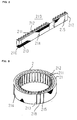
- FIG. 2 illustrates a laminated iron core piece 210 to be included in the laminated iron core 21.
- the laminated iron core piece 210 is configured in a rectangular-parallelepiped manner, by, as illustrated in FIG. 2 , laminating a predetermined number of magnetic thin plates each formed of a magnetic material and each having a predetermined length.
- Each of the magnetic thin plates is provided with a predetermined number of teeth 211 formed at one side portion thereof, spaced apart from one another by a predetermined distance; when these magnetic thin plates are laminated so as to configure the laminated iron core piece 210, the teeth 211 form a predetermined number of slots 212.
- a great number of magnetic thin plates laminated in a rectangular-parallelepiped manner are welded one another, so that a plurality of adhered welding portions 213, 214, and 215 are provided.
- FIG. 3 illustrates the laminated iron core 21, of the stator 2, formed in a ring-shaped manner.
- the laminated iron core 21 is formed as follows.
- the laminated iron core piece 210 illustrated in FIG. 2 is bent to be ring-shaped in such a way that the teeth 211 and the slots 212 are oriented to the center of the ring; then, both end portions 216 and 217 of the laminated iron core piece 210 are made to abut on each other and the abutting portions are welded to become a bonding portion 218.
- FIG. 4 symbolically illustrates the stator 2 in a state in which the stator winding 22 is mounted in the slots 212 of the laminated iron core 21.
- the stator winding 22 is mounted in the slots 212 of the rectangular-parallelepiped laminated iron core piece 210 illustrated in FIG. 2 , and then bent in a ring-shaped manner together with the laminated iron core piece 210.
- the laminated iron core piece 210 is bent in a ring-shaped manner, and both end portions 216 and 217 are adhered to each other at the bonding portion 218, so that the laminated iron core 21 is configured.
- the stator winding 22 is mounted on the unbent rectangular-parallelepiped laminated iron core piece 210 and then bent together with the laminated iron core piece 210; therefore, a coil end portion 221 of the stator winding 22 is arranged definitely in the vicinity of the bonding portion 218 of the laminated iron core 21.
- the respective end portions of the laminated iron core 21 formed in a ring-shaped manner are inserted into the corresponding inner circumferential portions of the end frames 51 and 52 in a pair and, as illustrated in FIG. 1 , tightened by the bolt 6 through the end frames 51 and 52.
- the dashed-dotted line A indicates the position of the bonding portion 218 of the laminated iron core 21; the dashed-dotted line B indicates the point-symmetric position of the position A of the bonding portion 218 of the laminated iron core 21.
- the position A of the bonding portion 218 and the position B are spaced apart by 180° from each other with respect to the center axis of the stator 2.
- a marking 7 for indicating inherent information about the stator 2 is provided at a predetermined position on the outer circumferential surface, of the laminated iron core 21, which is situated between the end frames 51 and 52 in a pair and exposed outward.
- the inherent information about a stator is information, such as in which place of which factory the stator has been manufactured, which is utilized for a product analysis in the case where, after being utilized as a product, the stator is obtained by the manufacturer; thus, no information is conveyed to a third person.
- the marking 7 is formed at a position that is a predetermined distance L away from the point-symmetric position B of the position A of the bonding portion 218 of the laminated iron core 21.
- the distance L is selected in such a way that, after the stator is integrated in an electric rotating machine, the marking is situated at a position that can be viewed from outside.
- the coil end portion 221 of the stator winding 22 is arranged definitely in the vicinity of the bonding portion 218 of the laminated iron core 21; the approximately middle portion of the coil end portion 221 corresponds to the position A of the bonding portion 218 of the laminated iron core 21. Accordingly, the position B on the outer circumferential surface of the laminated iron core 21 is also the point-symmetric position of the approximately middle portion of the coil end portion 221.
- the indication by the marking 7 may include, for example, inherent information about the whole electric rotating machine besides the inherent information about the stator. Additionally, the marking 7 may be provided by melting the outer circumferential surface of the laminated iron core 21 so as to form recesses, by means of an electric pen or the like, instead of a laser beam.
- the outer circumferential surface of the laminated magnetic thin plates may be utilized, as it is, as the outer circumferential surface of the laminated iron core 21; however, in this case, because being configured with the collective machining surfaces at which the magnetic thin plates are stamped out and being exposed outward, the outer circumferential surface of the laminated magnetic thin plates is liable to change in quality, for example, to rust. Accordingly, in order to prevent the outer circumferential surface of the laminated iron core 21 from changing in quality, a resin having a rust-proof effect is coated on the outer circumferential surface of the laminated iron core 21 so that a resin coating 8 is formed.
- the resin coating 8 is formed after, as illustrated in FIG. 4 , the marking 7 is provided on the outer circumferential surface of the laminated iron core 21. As a result, the marking 7 is covered with the resin coating 8, as illustrated in FIG. 5 ; however, because the resin coating 8 is transparent or semi-transparent, the marking 7 can be viewed from outside and is readily read.
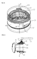
- FIG. 6 illustrates an example of a working process of coating a resin on the outer circumferential surface of the laminated iron core 21.
- the laminated iron core 21 and the stator winding 22 are fixed to the supporting member 9; while the supporting member 9 is rotated on a center axis 91 thereof, a liquid resin 12 is homogeneously blown off, from a nozzle 11 provided at the front end of a pipe 10, against the outer circumferential surface of the laminated iron core 21, so that the resin coating 8 is formed.
- the resin coating 8 can prevent change in quality due to rust or the like or deterioration with time from occurring on the outer circumferential surface of the laminated iron core 21.
- FIG. 7 is a perspective view symbolically illustrating a stator, of an electric rotating machine, according to Embodiment 2 of the present invention.
- Embodiment 2 by coating an opaque resin on the outer circumferential surface of the laminated iron core 21, the resin coating 8 is formed.
- the other configurations of the electric rotating machine and the stator 2, the configuration of and the formation method for the marking 7, and the formation method for the resin coating 8 are the same as those in Embodiment 1.
- FIG. 7 for convenience of explanation, a state is illustrated in which part of the resin coating 8 is peeled off so that part of the marking 7 provided on the outer circumferential surface of the laminated iron core 21 is exposed; however, because being usually covered with the resin coating 8, the marking 7 is not viewed from outside.
- the marking 7 may be exposed by peeling off or wiping off part of the opaque resin coating 8 with which the outer circumferential surface of the laminated iron core 21 is covered.
- the marking 7 is provided at a position that is the predetermined distance L away from the point-symmetry position B of the position A of the bonding portion of the laminated iron core 21; therefore, by, as an origin point, utilizing the point-symmetry position B of the position A of the bonding portion, the position of the marking can readily be determined. Accordingly, only the portion, of the resin coating 8, which corresponds to the marking 7 can be determined and removed, whereby there exists no possibility that the other portion of the resin coating is wiped off.
- the coil end portion 221 exists definitely at the position of the bonding portion 218 (refer to FIG. 3 ) of the laminated iron core 21, and the approximately middle position of the coil end portion 221 corresponds to the bonding portion 218 of the laminated iron core 21. Therefore, the position of the marking 7 may be determined by checking the approximately middle portion of the coil end portion 221 and, as an origin point, utilizing the point-symmetry position B of the approximately middle portion.
- the indication by the marking 7 cannot be recognized as long as the resin coating 8 is not peeled off. Accordingly, even information that should not be conveyed to a third person can be indicated by means of the marking 7; by ascertaining whether or not the indication exists, it is made possible to determine whether or not the electric rotating machine or the stator is manufactured in-house, i.e., whether or not the electric rotatingmachine or the stator is an illegal fake product, and eventually, manufacture and sale of illegal fake products can be prevented.
- FIG. 8 is an explanatory view for explaining another manufacturing process for a laminated iron core 21 of a stator, of an electric rotating machine, according to the present invention.
- the laminated iron core 21 is formed by continuously winding an elongated magnetic thin plate 200, having a great number of teeth 211 that are formed at one side portion and spaced a predetermined distance apart from one another, into a space across which a jig 13 and a jig 14 face each other.
- the position of the marking can readilybe determined even after the laminated iron core 21 is integrated in an electric rotatingmachine.
- the other configurations of the electric rotating machine and the stator thereof are the same as those in Embodiments 1 and 2.
- the resin coating may be transparent as in Embodiment 1 or opaque as in Embodiment 2.
- FIG. 9 is an explanatory view for explaining another manufacturing method for a laminated iron core 21 of a stator, of an electric rotating machine, according to the present invention.
- a laminated iron core 21 is formed by laminating a predetermined number of ring-shaped magnetic thin plates 201 each provided, at the inner side thereof, with a predetermined number of teeth 211 and a predetermined number of slots 212 formed of the teeth 211.
- the laminated iron core formed as described above as is the case with the laminated iron core illustrated in FIG. 8 , by, as a mark, regarding the position of the coil end portion of a stator winding (unillustrated) mounted in the slots 212 and providing a marking at a position that is a predetermined distance away from the point-symmetry position of the position of the coil end portion, the position of the marking can readilybe determined even after the laminated iron core 21 is integrated in an electric rotatingmachine.
- the other configurations of the electric rotating machine and the stator thereof are the same as those in Embodiments 1 and 2.
- the resin coating may be transparent as in Embodiment 1 or opaque as in Embodiment 2.
- a single laminated iron core may be configured in such a way that laminated iron core pieces formed in a rectangular-parallelepiped manner are bent into an arc-shaped laminated iron core, and a plurality of arc-shaped laminated iron cores are made to abut to one another and bonded with one another through welding. Because, in this case, the laminated iron core has a plurality of bonding portions, the position of a marking may be determined by, as a mark, utilizing any one of the positions of the bonding portions, or by, as a mark, utilizing the position of the coil end portion of a stator winding.
- the laminated iron core of a stator, of an electric rotating machine, according to the present invention may be a laminated iron core other than the foregoing laminated iron cores explained in Embodiments 1 and 2 and the Variant Example of Laminated Iron Core.
- a stator, of an electric rotating machine can be applied not only to the field of an electric rotating machine such as an AC generator mounted in an vehicle but also to an electric rotating machine utilized in all other fields.
Landscapes
- Engineering & Computer Science (AREA)
- Power Engineering (AREA)
- Manufacturing & Machinery (AREA)
- Iron Core Of Rotating Electric Machines (AREA)
- Manufacture Of Motors, Generators (AREA)
Applications Claiming Priority (1)
| Application Number | Priority Date | Filing Date | Title |
|---|---|---|---|
| PCT/JP2006/310472 WO2007138647A1 (ja) | 2006-05-25 | 2006-05-25 | 回転電機の固定子 |
Publications (3)
| Publication Number | Publication Date |
|---|---|
| EP2020731A1 true EP2020731A1 (de) | 2009-02-04 |
| EP2020731A4 EP2020731A4 (de) | 2013-12-25 |
| EP2020731B1 EP2020731B1 (de) | 2017-08-16 |
Family
ID=38778176
Family Applications (1)
| Application Number | Title | Priority Date | Filing Date |
|---|---|---|---|
| EP06746851.2A Ceased EP2020731B1 (de) | 2006-05-25 | 2006-05-25 | Stator einer dynamoelektrischen maschine |
Country Status (6)
| Country | Link |
|---|---|
| US (1) | US8508097B2 (de) |
| EP (1) | EP2020731B1 (de) |
| JP (1) | JP4859923B2 (de) |
| KR (1) | KR101161470B1 (de) |
| CN (1) | CN101390272B (de) |
| WO (1) | WO2007138647A1 (de) |
Cited By (1)
| Publication number | Priority date | Publication date | Assignee | Title |
|---|---|---|---|---|
| EP3086442A1 (de) * | 2015-04-22 | 2016-10-26 | Siemens Aktiengesellschaft | Elektrische maschine mit einem ersten aktivteil und einem zweiten aktivteil |
Families Citing this family (9)
| Publication number | Priority date | Publication date | Assignee | Title |
|---|---|---|---|---|
| JP5089677B2 (ja) * | 2009-12-10 | 2012-12-05 | 三菱電機株式会社 | 車両用回転電機 |
| US9231459B2 (en) | 2011-05-06 | 2016-01-05 | Qm Power, Inc. | Motor topology with exchangeable components to form different classes of motors |
| JP5776664B2 (ja) | 2012-10-19 | 2015-09-09 | 株式会社安川電機 | 回転電機、固定子結合体、及び結線基板 |
| US10670310B2 (en) * | 2013-01-28 | 2020-06-02 | Regal Beloit America, Inc. | Motor for use in refrigerant environment |
| JP5958565B2 (ja) | 2015-01-14 | 2016-08-02 | Jfeスチール株式会社 | 打抜き加工方法、打抜き加工装置、および積層鉄心の製造方法 |
| JP6694771B2 (ja) * | 2016-07-01 | 2020-05-20 | 株式会社三井ハイテック | 積層鉄心及びその製造方法 |
| JP6691161B2 (ja) * | 2018-03-28 | 2020-04-28 | ファナック株式会社 | 回転電機 |
| CN111934450B (zh) * | 2020-08-26 | 2021-09-28 | 珠海格力电器股份有限公司 | 一种磁悬浮轴承径向定子、磁悬浮轴承、安装方法及电机 |
| JP7835117B2 (ja) * | 2022-06-01 | 2026-03-25 | 株式会社豊田自動織機 | 回転電機 |
Family Cites Families (22)
| Publication number | Priority date | Publication date | Assignee | Title |
|---|---|---|---|---|
| US3436812A (en) * | 1965-10-06 | 1969-04-08 | Nippon Denso Co | Method of making the stator core for rotary electric machinery |
| JPS53103101A (en) * | 1977-02-22 | 1978-09-08 | Toshiba Corp | Winding type rotator |
| GB2062972B (en) * | 1979-10-19 | 1983-08-10 | Nippon Steel Corp | Iron core for electrical machinery and apparatus and well as method for producing the iron core |
| DE3728622C1 (de) * | 1987-08-27 | 1988-05-19 | Daimler Benz Ag | Kennzeichnung von industriellen Erzeugnissen oder Einzelteilen davon |
| US4822987A (en) * | 1988-01-25 | 1989-04-18 | Westinghouse Electric Corp. | Method and apparatus for providing fuel rod identification to permit traceability during manufacture and use |
| GB8802054D0 (en) * | 1988-01-29 | 1988-02-24 | Baugh J J | Method of marking object using laser beam & method & device for use in reading bar code |
| JPH0438148A (ja) * | 1990-05-31 | 1992-02-07 | Mitsuba Electric Mfg Co Ltd | 車両用発電機 |
| JPH06253479A (ja) | 1993-02-26 | 1994-09-09 | Nippon Densan Corp | ステータコア |
| JP3457048B2 (ja) * | 1994-02-28 | 2003-10-14 | 三菱電機株式会社 | 電動機ステータ、電動機ステータ自動供給装置及び電動機ステータ自動供給方法 |
| EP0681252A1 (de) * | 1994-05-06 | 1995-11-08 | Takaharu Honda | Verfahren zur Codierung einem chirurgischen Instrumentes und chirurgisches Instrument mit einem Code |
| JPH09107650A (ja) | 1995-10-12 | 1997-04-22 | Hitachi Ltd | 車両用交流発電機 |
| JP2000278892A (ja) * | 1999-03-19 | 2000-10-06 | Mitsubishi Electric Corp | 車両用交流発電機の固定子コア及び車両用交流発電機の固定子コアの製造方法 |
| JP2002238191A (ja) | 2001-02-08 | 2002-08-23 | Isuzu Motors Ltd | 回転機の回転子 |
| US6451421B1 (en) * | 2001-03-19 | 2002-09-17 | Infosight Corporation | Laser markable micro-pore aluminum tags and method of their fabrication |
| JP3621653B2 (ja) * | 2001-03-28 | 2005-02-16 | 三菱電機株式会社 | 回転電機の固定子および固定子鉄心並びにその製造方法 |
| JP2002346633A (ja) * | 2001-05-29 | 2002-12-03 | Daido Steel Co Ltd | レーザーマーキング方法 |
| JP2004336987A (ja) * | 2003-04-18 | 2004-11-25 | Aisin Aw Co Ltd | モータ製造ライン及びその制御方法 |
| WO2004095676A1 (ja) * | 2003-04-18 | 2004-11-04 | Aisin Aw Co. Ltd. | モータ製造ライン及びその制御方法 |
| JP2005084962A (ja) * | 2003-09-09 | 2005-03-31 | Ntn Corp | Icタグ付き機械要素部品 |
| JP2005203695A (ja) * | 2004-01-19 | 2005-07-28 | Casio Micronics Co Ltd | 半導体装置およびその製造方法 |
| JP2005226808A (ja) | 2004-02-16 | 2005-08-25 | Mitsubishi Electric Corp | 電磁弁 |
| US7005603B2 (en) * | 2004-04-02 | 2006-02-28 | Hewlett-Packard Development Company, L.P. | Laser marking |
-
2006
- 2006-05-25 KR KR1020087016644A patent/KR101161470B1/ko not_active Expired - Fee Related
- 2006-05-25 CN CN2006800534178A patent/CN101390272B/zh not_active Expired - Fee Related
- 2006-05-25 JP JP2008517712A patent/JP4859923B2/ja not_active Expired - Fee Related
- 2006-05-25 WO PCT/JP2006/310472 patent/WO2007138647A1/ja not_active Ceased
- 2006-05-25 EP EP06746851.2A patent/EP2020731B1/de not_active Ceased
- 2006-05-25 US US12/161,850 patent/US8508097B2/en not_active Expired - Fee Related
Cited By (1)
| Publication number | Priority date | Publication date | Assignee | Title |
|---|---|---|---|---|
| EP3086442A1 (de) * | 2015-04-22 | 2016-10-26 | Siemens Aktiengesellschaft | Elektrische maschine mit einem ersten aktivteil und einem zweiten aktivteil |
Also Published As
| Publication number | Publication date |
|---|---|
| US8508097B2 (en) | 2013-08-13 |
| EP2020731A4 (de) | 2013-12-25 |
| US20090021101A1 (en) | 2009-01-22 |
| CN101390272B (zh) | 2011-11-30 |
| JP4859923B2 (ja) | 2012-01-25 |
| JPWO2007138647A1 (ja) | 2009-10-01 |
| KR20080092360A (ko) | 2008-10-15 |
| EP2020731B1 (de) | 2017-08-16 |
| KR101161470B1 (ko) | 2012-07-02 |
| CN101390272A (zh) | 2009-03-18 |
| WO2007138647A1 (ja) | 2007-12-06 |
Similar Documents
| Publication | Publication Date | Title |
|---|---|---|
| EP2020731B1 (de) | Stator einer dynamoelektrischen maschine | |
| JP5243511B2 (ja) | 永久磁石式同期モータの製造方法 | |
| WO2008047942A1 (en) | Stator core and rotating electrical machine | |
| US10666103B2 (en) | Rotor of rotating electric machine | |
| US7915780B2 (en) | Laminated spiral core, dynamo-electric-machine rotor provided therewith, and dynamo-electric machine | |
| JP2013150479A (ja) | 分割式コアを有する電動機の回転子及びその製造方法 | |
| US20140265699A1 (en) | Rotor for rotary electric machine and motor for electric power steering | |
| JP2006311738A (ja) | 永久磁石式同期モータおよびその製造方法 | |
| JP6428696B2 (ja) | ハイブリッドパワーユニット用モータの回転センサ取付構造 | |
| EP3490112A1 (de) | Rotor und rotationsmaschine | |
| EP2149962A2 (de) | Magnetfeldmotor und Herstellungsverfahren dafür | |
| EP3852241A1 (de) | Elektromotor und verfahren zur herstellung eines elektromotors | |
| JP2020048268A (ja) | 電動モータおよび電動モータの製造方法 | |
| EP2830199B1 (de) | Rotierende elektrische Maschine und Sattelfahrzeug | |
| CN101978583B (zh) | 车辆用旋转电机 | |
| US20100072864A1 (en) | Motor Assembly with Sensor Target on Motor Rotor and Method of Forming Same | |
| CN101459366B (zh) | 永磁体型同步电动机及其制造方法 | |
| JP3793863B2 (ja) | 磁気軸受のステータユニットの製造方法 | |
| US20220344981A1 (en) | Laminated core of electric machine, electric machine, method for manufacturing laminated core of electric machine, and method for manufacturing electric machine | |
| CN100391087C (zh) | 电动机 | |
| JP5387528B2 (ja) | ステータコアの製造方法 | |
| CN202652036U (zh) | 马达 | |
| WO2022029842A1 (ja) | 回転電機およびその製造方法 | |
| JP6298420B2 (ja) | モータの固定子構造及びモータ | |
| JP3003308U (ja) | 回転電機の軸受支持構造 |
Legal Events
| Date | Code | Title | Description |
|---|---|---|---|
| PUAI | Public reference made under article 153(3) epc to a published international application that has entered the european phase |
Free format text: ORIGINAL CODE: 0009012 |
|
| 17P | Request for examination filed |
Effective date: 20080715 |
|
| AK | Designated contracting states |
Kind code of ref document: A1 Designated state(s): AT BE BG CH CY CZ DE DK EE ES FI FR GB GR HU IE IS IT LI LT LU LV MC NL PL PT RO SE SI SK TR |
|
| AX | Request for extension of the european patent |
Extension state: AL BA HR MK YU |
|
| DAX | Request for extension of the european patent (deleted) | ||
| RBV | Designated contracting states (corrected) |
Designated state(s): CZ DE FR |
|
| A4 | Supplementary search report drawn up and despatched |
Effective date: 20131125 |
|
| RIC1 | Information provided on ipc code assigned before grant |
Ipc: H02K 1/12 20060101ALI20131119BHEP Ipc: H02K 15/00 20060101ALI20131119BHEP Ipc: H02K 1/18 20060101AFI20131119BHEP |
|
| 17Q | First examination report despatched |
Effective date: 20160316 |
|
| GRAP | Despatch of communication of intention to grant a patent |
Free format text: ORIGINAL CODE: EPIDOSNIGR1 |
|
| INTG | Intention to grant announced |
Effective date: 20170209 |
|
| GRAS | Grant fee paid |
Free format text: ORIGINAL CODE: EPIDOSNIGR3 |
|
| GRAJ | Information related to disapproval of communication of intention to grant by the applicant or resumption of examination proceedings by the epo deleted |
Free format text: ORIGINAL CODE: EPIDOSDIGR1 |
|
| GRAL | Information related to payment of fee for publishing/printing deleted |
Free format text: ORIGINAL CODE: EPIDOSDIGR3 |
|
| GRAR | Information related to intention to grant a patent recorded |
Free format text: ORIGINAL CODE: EPIDOSNIGR71 |
|
| INTC | Intention to grant announced (deleted) | ||
| GRAA | (expected) grant |
Free format text: ORIGINAL CODE: 0009210 |
|
| AK | Designated contracting states |
Kind code of ref document: B1 Designated state(s): CZ DE FR |
|
| INTG | Intention to grant announced |
Effective date: 20170707 |
|
| REG | Reference to a national code |
Ref country code: DE Ref legal event code: R096 Ref document number: 602006053348 Country of ref document: DE |
|
| REG | Reference to a national code |
Ref country code: FR Ref legal event code: PLFP Year of fee payment: 13 |
|
| REG | Reference to a national code |
Ref country code: DE Ref legal event code: R097 Ref document number: 602006053348 Country of ref document: DE |
|
| PLBE | No opposition filed within time limit |
Free format text: ORIGINAL CODE: 0009261 |
|
| STAA | Information on the status of an ep patent application or granted ep patent |
Free format text: STATUS: NO OPPOSITION FILED WITHIN TIME LIMIT |
|
| 26N | No opposition filed |
Effective date: 20180517 |
|
| PGFP | Annual fee paid to national office [announced via postgrant information from national office to epo] |
Ref country code: CZ Payment date: 20190429 Year of fee payment: 14 |
|
| PGFP | Annual fee paid to national office [announced via postgrant information from national office to epo] |
Ref country code: DE Payment date: 20200512 Year of fee payment: 15 |
|
| REG | Reference to a national code |
Ref country code: DE Ref legal event code: R084 Ref document number: 602006053348 Country of ref document: DE |
|
| PG25 | Lapsed in a contracting state [announced via postgrant information from national office to epo] |
Ref country code: CZ Free format text: LAPSE BECAUSE OF NON-PAYMENT OF DUE FEES Effective date: 20200525 |
|
| REG | Reference to a national code |
Ref country code: DE Ref legal event code: R119 Ref document number: 602006053348 Country of ref document: DE |
|
| PG25 | Lapsed in a contracting state [announced via postgrant information from national office to epo] |
Ref country code: DE Free format text: LAPSE BECAUSE OF NON-PAYMENT OF DUE FEES Effective date: 20211201 |
|
| PGFP | Annual fee paid to national office [announced via postgrant information from national office to epo] |
Ref country code: FR Payment date: 20220408 Year of fee payment: 17 |
|
| P01 | Opt-out of the competence of the unified patent court (upc) registered |
Effective date: 20230512 |
|
| PG25 | Lapsed in a contracting state [announced via postgrant information from national office to epo] |
Ref country code: FR Free format text: LAPSE BECAUSE OF NON-PAYMENT OF DUE FEES Effective date: 20230531 |