EP2022710A2 - Abdeckung, Schlauchbefestigungsstruktur und im Grätschsitz zu führendes Fahrzeug - Google Patents
Abdeckung, Schlauchbefestigungsstruktur und im Grätschsitz zu führendes Fahrzeug Download PDFInfo
- Publication number
- EP2022710A2 EP2022710A2 EP08252511A EP08252511A EP2022710A2 EP 2022710 A2 EP2022710 A2 EP 2022710A2 EP 08252511 A EP08252511 A EP 08252511A EP 08252511 A EP08252511 A EP 08252511A EP 2022710 A2 EP2022710 A2 EP 2022710A2
- Authority
- EP
- European Patent Office
- Prior art keywords
- reservoir
- hose
- cover
- port
- side wall
- Prior art date
- Legal status (The legal status is an assumption and is not a legal conclusion. Google has not performed a legal analysis and makes no representation as to the accuracy of the status listed.)
- Granted
Links
Images




Classifications
-
- B—PERFORMING OPERATIONS; TRANSPORTING
- B62—LAND VEHICLES FOR TRAVELLING OTHERWISE THAN ON RAILS
- B62J—CYCLE SADDLES OR SEATS; AUXILIARY DEVICES OR ACCESSORIES SPECIALLY ADAPTED TO CYCLES AND NOT OTHERWISE PROVIDED FOR, e.g. ARTICLE CARRIERS OR CYCLE PROTECTORS
- B62J35/00—Fuel tanks specially adapted for motorcycles or engine-assisted cycles; Arrangements thereof
Definitions
- the present invention relates to a cover, a hose fixing structure and a straddle-type vehicle.
- JP-A-05-330468 discloses a cover structured such that a tray formed from a flexible member is provided on a filling portion of a fuel tank, an upright and inwardly bent side wall is formed above the tray, and when abutting against a bottom plate of a seat upon closure of the seat, the side wall is pushed by the bottom plate of the seat to be bent inward.
- the side wall of the tray formed from a flexible member is held down by the bottom plate of the seat.
- the bottom plate of the seat contacts with an outer side of the side wall and does not abut against an inner side polluted by a fuel.
- the side wall is not deformed outward but deformed inward, so that the bottom plate of the seat contacts with the outer side of the side wall but does not abut against the inner side polluted by a fuel.
- JP-A-2003-054468 discloses a construction in which a cover covers the whole of an upper portion of a fuel tank to provide a concave tray, a recess is formed between a helmet box of the cover and the fuel tank, and a drain hose is connected to a bottom of the recess.
- a cover covers the whole of the upper portion of the fuel tank to provide the concave tray, it is possible to ensure a large volume in the tray and to surely prevent gasoline from overflowing from the tray without enlarging a diameter of a drain pipe.
- the cover since the whole of the upper portion of the fuel tank is covered by the cover, a periphery of the fuel tank is not exposed outside in a state, in which a seat is opened, so that the periphery of the fuel tank is improved in outward appearance.
- the cover described above is a member which receives fuel overflowing from a feed oil port of a fuel tank at the time of fueling and distributes the fuel appropriately through a drain hose. Therefore, it is desirable to provide a sufficient volume to receive a fuel overflowing from the feed oil port of the fuel tank.
- JP-A-05-330468 the upright and inwardly bent side wall is formed above the tray, and when abutting against the bottom plate of the seat upon closure of the seat, the side wall is pushed by the bottom plate of the seat to be bent inward, and it is directed to prevent the bottom plate of the seat from being polluted by fuel.
- JP-A-2003-054468 a volume is ensured by having the cover covering the whole of the upper portion of the fuel tank to provide the concave tray and forming the recess between the helmet box of the cover and the fuel tank.
- such construction is materialized in a construction, in which a helmet box is arranged forwardly of a fuel tank, and so such construction cannot be adopted in some cases.
- a cover adapted to be arranged around a port on a surface of a tank arranged to receive a liquid through said port, wherein the cover comprises:
- the roof may be inclined.
- the roof may define a pent roof.
- the port may alternatively be defined as a tap.
- a side end of the roof may be contiguous to the side wall provided upright around the reservoir.
- the side wall may extend around the port from a periphery of the reservoir.
- a bottom of the reservoir may be inclined to become deeper towards the side wall from the port.
- the cover may further comprise a drain hole formed in a deepest region of the reservoir.
- the roof may extend above a deepest region of the reservoir.
- a hose fixing structure may be provided which is adapted to fix a hose connected to the drain hole to a back surface of a plastic molded part that has one side with a cosmetic surface.
- Such a hose fixing structure may be provided in accordance with an aspect of the present invention.
- the hose fitting structure may comprise a support sections provided on the back surface for supporting sides of the hose, such as opposing sides of the hose.
- the support sections may extend in a die cutting direction of the plastic molded part.
- a stopper member may be provided and may be attached to at least one of the support sections and adapted to hold the hose between the support sections.
- a gap may be formed that allows the hose to be inserted between at least one support section and the stopper member.
- a boss section may be formed on at least one support section.
- the stopper member may be screwed to the boss section.
- An outer region of the stopper member may curve in a direction away from a back surface thereof.
- a gap may be formed that allows the hose to be inserted between at least one support section and the stopper member.
- the stopper member may comprise a washer.
- the stopper member may comprise a tab or the like.
- a hose fixing structure may be provided for fixings a hose connected to the drain hole defined above to a back surface of a vehicle outer cover that is plastic moulded.
- the outer cover may include support sections that support the hose and extend in a die cutting direction of the outer cover.
- a stopper member that holds the hose between the support sections may be attached to at least one of the support sections.
- the outer cover may include a guide for guiding the hose so that a discharge hole of the hose faces away from an associated vehicle and toward a road surface.
- a straddle-type vehicle comprising a cover defined above.
- a straddle-type vehicle comprising:
- a straddle-type vehicle comprising:
- the side wall provided upright around the reservoir may extend laterally of the port from a periphery of the reservoir.
- a cover according to an aspect of the invention is arranged around a tap, through which a liquid is poured, on an upper surface of a tank, is in the form of a tray to receive a liquid overflowing from the tap, and is formed with a reservoir, in which a liquid overflowing from the tap stays.
- a side wall is provided upright around the reservoir and a pent roof is extended above the reservoir from the side wall.
- a bottom of the reservoir may be inclined to become deep as it goes toward the side wall from the tap.
- a drain hole is formed in a deepest region of the reservoir and the pent roof may be extended above the drain hole.
- a hose fixing structure of the invention comprises support sections, provided on a back surface of a plastic molded part with a cosmetic surface on one side thereof, that support both sides of the hose arranged along the back surface.
- the support sections extend in a die cutting direction of the plastic molded part and a stopper member that holds the hose between the support sections at either side is attached to at least one of the support sections.
- a gap may be formed that allows the hose to be inserted between the support sections at either side and the stopper member.
- a boss section may be formed on the support sections, and the stopper member may be screwed to the boss section.
- the stopper member may be a washer.
- an outer circumference of the washer may curve in a direction away from the back surface, and a gap may be formed that allows the hose to be inserted between the support sections at either side and the washer.
- the outer cover preferably comprises support sections that support both sides of the hose arranged along the back surface.
- the support sections extend in a die cutting direction of the plastic molded part and a stopper member that holds the hose between the support sections at either side is attached to at least one of the support sections.
- the outer cover may include a guide for guiding the hose so that a discharge hole of the hose faces away from the vehicle and toward a road surface.
- the side wall is provided upright around the reservoir, in which a liquid overflowing from the tap of the tank stays, and the pent roof is extended above the reservoir from the side wall. Accordingly, even when an overflowing liquid strikes against the side walls to become choppy or turbulent, the liquid is prevented by the pent roof from getting over the side wall.
- the reservoir is formed to be deeper than therearound, so that the reservoir is improved in volume.
- the liquid is hard to spill outside the cover since the pent roof is present above the deepest region of the reservoir, in which a liquid overflowing from the tap stays.
- a hose fixing structure can be molded by a simple, split die since the support sections extend in a die cutting direction of the plastic molded part.
- a stopper member that holds the hose between the support sections at either side is attached to at least one of the support sections. Therefore, any influences in outward appearance are not exerted on the cosmetic surface.
- the stopper member is formed with a gap, between the support sections at either side, that allows the hose to be inserted between the support sections, it is possible to mount and dismount the hose in a state, in which the stopper member is attached to the support section, so that the work in mounting of the hose and in maintenance is facilitated.
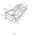
- a cover 100 is arranged as shown in Fig. 1 to cover an upper portion of a fuel tank 300 arranged below a seat 200 of a vehicle.
- the cover 100 is arranged around a feed oil port 310 (also defined as a tap, spout or the like) on an upper surface of the fuel tank 300 to assume a tray shape for receiving fuel overflowing from the feed oil port 310.
- the cover 100 is formed on an upper surface thereof with an opening 110, which exposes the feed oil port 310 of the fuel tank 300.
- An edge 111 of the opening 110 becomes upwardly protuberant.
- a periphery 112 of the edge 111 of the opening 110 is a little lower than the edge 111 and a further periphery 113 thereof is lower by a step than the periphery 112 of the edge 111.
- the cover 100 is formed with a reservoir 120, in which fuel overflowing from the feed oil port 310 is retained.
- the cover 100 is lower on a front side of the upper surface of the fuel tank 300 and the reservoir 120 is formed on a front side of the upper surface of the cover 100.
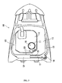
- a front side wall 121 extending left and right and a pair of left and right side walls 122, 123 extending longitudinally are provided upright around the reservoir 120, and both left and right ends of the front side wall 121 and front ends of the both left and right side walls 122, 123 are contiguous to each other.
- a roof 124 in this embodiment a pent roof, is provided above the reservoir 120. The pent roof 124 extends rearward over a whole width region from an upper edge of the front side wall 121, and both left and right ends of the pent roof 124 are contiguous to upper edges at the front ends of the both left and right side walls 122, 123.
- the pent roof 124 is extended above the reservoir 120 on the front side of the cover 100 from the front side wall 121 of the cover 100 and corners of the front side wall 121 and the left and right side walls 122, 123.
- a storage space is formed in the reservoir 120which is configured to be opened only toward a rear surface (that is, toward the feed oil port 310).
- the front side wall 121 is made intact in level and the pent roof 124 extending from the front side wall 121 is inclined so as to be upwardly sloped rearward along the bottom plate of the seat 200.
- a rear edge (that is, an opened edge toward a rear surface of the storage space) of the pent roof 124 is ensured to be sufficiently high in level, and the storage space is ensured to be sufficiently large in volume.
- a bottom 125 of the reservoir 120 is inclined to become deeper towards the side wall 121 from the feed oil port 310 as shown in Fig. 1 .
- the periphery 112 around the edge 111 of the opening 110 is a little lower than the edge 111 and the periphery 113 thereof is lower by a step than the periphery 112 of the edge 111 as shown in Fig. 1 .
- the bottom 125 of the reservoir 120 is inclined to become deeper towards the side wall 121 from the region 113.
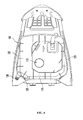
- Fig. 4 shows a bottom surface of the cover 100.
- a drain hole 130 is formed in a deepest region of the reservoir 120 as shown in Figs. 3 and 4 .
- the pent roof 124 is extended above the deepest region of the reservoir 120.
- side ends 124a, 124b of the pent roof 124 extended above the reservoir 120 are connected to the side walls 122, 123 provided upright around the reservoir 120 as shown in Fig. 2 .
- the pent roof 124 has a stable configuration in a state of being extended above the reservoir 120.
- the side walls 122, 123 provided upright around the reservoir 120 are extended around the opening 110, in which the tap or port 310 (see Fig. 1 ) is exposed, from a periphery of the reservoir 120. Thereby, fuel overflowing from the tap 310 is further surely led into the reservoir 120 along the side walls 122, 123.
- the cover 100 is made of rubber and formed integrally.
- a drain hose (not shown) is connected to the drain hole 130.
- the drain hose is preferably made integral with the cover 100 by means of, for example, bonding.
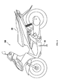
- a straddle-type vehicle 1000 is put in an inclined state by a side stand 500 as shown in Fig. 6 .
- the cover 100 is arranged around the tap 310, through which a liquid is poured, on the upper surface of the fuel tank 300 arranged on the straddle-type vehicle 1000.
- the drain hole 130 is formed on that side (left side) of the reservoir 120, which becomes the under or lower side when put in an inclined state by the side stand 500.
- the cover 100 is arranged around the tap 310 (feed oil port), through which fuel is poured, on the upper surface of the fuel tank 300 arranged below the seat 200 of the straddle-type vehicle 1000 as shown in Fig. 1 .
- the reservoir 120 is formed forwardly of the tap 310 on the cover 100.
- the side walls 122, 123 are provided upright around the reservoir 120 and the pent roof is extended above the reservoir 120 from the side walls 121, 122, 123. Further, the side walls 122, 123 provided upright around the reservoir 120 are extended laterally of the tap 310 from a periphery of the reservoir 120.
- the straddle-type vehicle 1000 is designed as shown in Fig. 6 so that a front side of the seat is relatively low so as to permit a driver to readily place their feet on the ground in a state of being seated on the seat 200. Further, the straddle-type vehicle 1000 is frequently designed such that the seat 200 is increased in height toward the rear thereof in order to maintain a driver in a forward tilting posture, or to provide a seat 200 for a tandem rider on the rear. Therefore, the upper surface of the fuel tank 300 arranged below the seat 200 is frequently low on the front thereof and high on the rear thereof as shown in Fig. 1 .
- a non-waste configuration in which the front side of the seat 200 is conformed to a shape of the upper surface of the fuel tank 300 with a front side thereof being low, is provided by forming the reservoir 120 forwardly of the tap 310.
- the side walls 122, 123 provided upright around the reservoir 120 are extended laterally of the tap 310 from the periphery of the reservoir 120.
- the side wall 122 or 123 is preferably extended laterally of the tap 310 from the periphery of the reservoir 120 at least on that side, which becomes the under or lower side when being put in an inclined state by the side stand 500.
- the side walls 121, 122, 123 are provided upright around the reservoir 120, in which a fuel overflowing from the feed oil port 310 of the fuel tank 300 stays, and the pent roof 124 is extended above the reservoir 120 from the side walls 121, 122, 123. Accordingly, even when fuel overflowing from the feed oil port 310 and flowing forward toward the reservoir 120 strikes against the front side wall 131 to become choppy or turbulent, there is minimal risk that the fuel will spill or splash over the side wall 121 since the pent roof 124 is present above the turbulent region.
- the reservoir 120 is formed to be deeper than the surrounding region, so that the reservoir 120 is improved in volume.
- the straddle-type vehicle 1000 parks with the use of the side stand 500, the straddle-type vehicle 1000 is inclined a little.
- the pent roof 124 is extended above the reservoir 120 on the front side of the cover 100 from the front side wall 121 of the cover 100 and corners of the front side wall 121 and the left and right side walls 122, 123, so that even when the straddle-type vehicle 1000 is inclined a little, it is possible to prevent fuel from spilling from the reservoir 120.
- the bottom 125 of the reservoir 120 is inclined to become deeper towards the side wall 121 from the feed oil port 310 as shown in Fig. 5 . Therefore, fuel spilling from the feed oil port 310 flows to the reservoir 120 along the slope of the bottom 125 as indicated by an arrow a in Fig. 5 . When flowing to the reservoir 120, fuel flows downward once along the slope of the bottom 125, so that is difficult for the fuel to spill outside the cover 100 over the pent roof 124 disposed above the side wall 121.
- the bottom 125 of the reservoir 120 is inclined to become deeper towards the side wall 121 from the feed oil port 310, so that flow of fuel to the reservoir 120 can be controlled and it is difficult for the fuel to spill outside the cover 100 over the pent roof 124.
- the drain hole 130 is formed in the deepest region of the reservoir 120 and the pent roof 124 is extended above the deepest region of the reservoir 120.
- the pent roof 124 is present above the deepest region of the reservoir 120, in which a fuel overflowing from the feed oil port 310 is retained, so that it is difficult for fuel to spill outside the cover 100.
- the cover according to the invention is not limited to the embodiment.
- a specific shape of the cover, etc. can be modified variously as far as the scope of the invention is not changed.
- the pent roof 124 has been illustrated as being extended above the reservoir 120 on the front side of the cover 100 from the front side wall 121 of the cover 100 and corners off the front side wall 121 and the left and right side walls 122, 123, the invention is not limited to such configuration.
- the reservoir is not necessarily disposed on the front side of the cover.
- the pent roof is preferably disposed in an appropriate position to assume an appropriate configuration and extended from the side walls so that the reservoir of the cover is increased in volume and a liquid overflowing from the tap of the tank does not spill from the cover.
- the reservoir is formed on the front side of the cover in the embodiment, the reservoir may be present on the side of the cover.
- a reservoir may be provided on that side, which becomes the under or lower side when being put in an inclined state by a side stand, in the case where the straddle-type vehicle is put in an inclined state by the side stand.
- the cover mounted around the tap on the upper surface of the fuel tank is arranged below the seat of the straddle-type vehicle.
- the cover according to the invention is not limited to such a cover.
- the cover is applicable to taps, ports, spouts or the like of various tanks such as a radiator cooling water filler hole on a radiator cooling water tank, an oil filler hole on an engine oil tank.
- the invention is applicable to various covers arranged around a tap, through which a liquid is poured, on an upper surface of various tanks, and having a tray shape to receive a liquid overflowing from the tap.
- the side walls are provided upright around the reservoir, in which liquid overflowing from the tap of the tank stays, and the pent roof is extended above the reservoir from the side walls, so that it is difficult for fuel overflowing from the feed oil port of the fuel tank to spill from the cover. Therefore, the cover is preferred as a cover for a fuel tank of a straddle-type vehicle.
- the straddle-type vehicle includes, in addition to various vehicles ridden in a straddle-type posture, scooter type motorcycles, snowmobiles, four-wheeled buggies, etc.
- some vehicles are equipped with a cover on a feed oil port of the fuel tank that receives fuel spilled during fueling as described in the above first embodiment.
- This type of cover includes a tray section where spilled fuel stays. A drain hole is formed at the bottom of the tray and a drain hose is connected to this drain hole.
- fuel spilled from the feed oil port stays in the tray section passes through the drain hole and the drain hose, and then discharges out to the exterior.
- the drain hose is normally fixed to the frame of the vehicle using some kind of fixing fixture (for example, as described in JP-A-2002-362459 and JP-A-2004-66937 ).
- any frame is not present in a position, in which it is desired to arrange a drain hose
- the outer side of the outer cover creates the outward appearance of the vehicle and, as a cosmetic surface, it is painted and has a mirror finish.
- Fixing a drain hose on the back surface is undesirable since it would affect the outward appearance of the face or cosmetic surface of the outer cover or reduce the strength of the outer cover. For this reason, as shown in Fig.
- a method in which a drain hose is attached to a back surface 22 of an outer cover 56 by screwing in a fixing fixture 80 that fixes the drain hose 54 cannot be used when design is being emphasized because it exposes unnecessary screws on a cosmetic surface 21. Also, because the screw holes form perforations, the strength of the cosmetic surface may be reduced.
- component costs may increase due to slide moulding, etc. being necessary.
- a hose fixing structure 10 fixes a hose 30 to the back surface 22 of a plastic molded part 20 that has one side with a cosmetic surface 21.
- the hose 30 is arranged along the back surface 22.
- the back surface 22 is provided with support sections 31, 32 that support both sides of the hose 30. These support sections 31, 32 extend in a die cutting direction of a plastic molded part 20.
- a stopper member 40 is attached to at least one of the support sections 31, 32, and holds the hose 30 in between both the support sections 31, 32.
- the hose fixing structure 10 includes support sections 31, 32 that extend in the die cutting direction of the plastic molded part 20 and separately includes the stopper member 40, so the structure can be formed in a simple split die.
- the plastic molded part 20 which is not shown in the figures, can be formed with a pair of metal moulds including a first metal mould for forming the cosmetic surface 21 and a second metal mould for forming the back surface 22.
- the support sections 31, 32 can be removed from the mould in generally the normal line direction of the back surface 22.
- the stopper member 40 that holds the hose 30 between the supports sections 31, 32 at either side is attached to at least one of the supports sections 31, 32. The stopper member 40 is attached to the support section 32, and this attachment structure has no effect on the outward appearance on the cosmetic surface 21.
- the above hose fixing structure 10 can be used as a fixing structure for various types of hoses.
- the above-described fuel drain hose it can be used as a fixing structure for an air conditioner drain hose, or hoses that bound together cables.
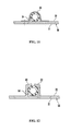
- ribs 33, 34 are formed as appropriate on the support sections 31, 32.
- a boss section 35 is formed on the support section 32 at one side.
- a screw hole 36 is formed in the boss section 35.
- the stopper member 40 is a washer, and the stopper member 40 is fixed to the boss section 35 by a screw 41.
- An outer circumference section 42 of the washer 40 curves away from the back surface 22. This forms a gap 43 that allows the hose 30 to be inserted between the support sections 31, 32 at either side.
- This embodiment includes the gap 43 that allows the hose 30 to be inserted in between the support sections 31, 32 at either side, and thus the installation and removal of the hose 30 can be performed when the stopper member 40 is attached to the support section 32. This makes it easier to perform the work done when removing and installing the hose 30, or maintaining the hose 30. It is desirable that the gap 43 that allows the hose 30 to be inserted between the support sections 31, 32 at either side is desirable for the hose 30 to be installed and removed during maintenance, etc. when the stopper member 40 is attached, while at the same time allowing the function of the stopper member 40, ie, holding the hose 30 between the support sections 31, 32 at either side during normal vehicle travel, to be maintained.
- the boss section 35 is formed on the support section 32 at one side, and the washer 40 (the stopper member) is screw fixed to the boss section 35. Accordingly, even if a screw is used for fixing, the screw hole 36 can be formed in the boss section 35 and there is no effect on the outward appearance of the cosmetic surface 21.
- a configuration with a washer being used for the stopper member 40 is given as an example.
- Washers are common parts that can be obtained at a low cost and this is one member that is suitable for use as the stopper member 40 of the invention.
- the outer circumference 42 of the washer 40 (the stopper member) curves away from the back surface 22 such that the gap 43 which allows the hose 30 to be inserted between the support sections 31, 32 at either side is formed.
- the shape of a washer is the same in the circumferential direction, and so there is no effect on the gap 43 even if the washer is turned when it is screw fixed. This is another feature that makes a washer suitable for use as the stopper member 40 of the invention.
- the stopper member 40 is not limited to being a washer.
- a member with a shape that is suitable for holding the hose 30 can be used.
- a tab 40a can be used for the stopper member instead of a washer.
- a rotation stopping structure for stopping rotation of the tab 40a may be used.
- a portion of the tab 40a may include a rotation stopper that engages with a portion of the supporting section 32. Additionally, the rotation stopper member that stops rotation of the tab 40a may be aligned and screw fixed.
- the attachment structure for the stopper member is not limited to just a screw-in type.
- the stopper member 40 may be adhered on, or an appropriate fitting structure or engagement structure may be formed in between the boss section 35 and stopper member 40, and the stopper member 40 may be attached using this fitting structure or engagement structure.
- the stopper member 40 may be attached to both of the support sections 31, 32 at either side or the stopper member 40 may attached so that it extends between the support sections 31, 32 at either side.
- the stopper member 40 is attached to the support section 32 at one side so as to form the gap 43 that allows the hose 30 to be inserted between the supporting sections 31, 32 at either side.
- a vehicle 50 as shown in Fig. 9 is a scooter motorcycle. Furthermore, a fuel tank 51 is attached to a frame 53 supporting a seat 52. The drain hose 54 is arranged so that it faces down in relation to the vehicle 50 from the area around a feed oil port of the fuel tank 51. A portion of the drain hose 54 is fixed to the frame 53 and another portion of the drain hose 54 is fixed to the back surface 22 of the outer cover 56 arranged on the lower side surface of the seat 52 so that the drain hose 54 is arranged in a predetermined position.
- Fig. 10 shows the back surface 22 of the outer cover 56. The drain hose 54, as shown in Fig. 10 , is arranged along the back surface 22 of the outer cover 56.
- a hose fixing structure 70 includes the predetermined position at which the drain hose 54 is fixed on the back surface 22 of the outer cover 56.
- the back surface of the outer cover 56 includes the support sections 31, 32 that support both sides of the drain hose 54 at the predetermined position at which the drain hose 54 is fixed.
- the support sections 31, 32 extend in the die cutting or separation direction of the outer cover 56.
- the hose fixing structure 70 has the same structure as the hose fixing structure 10 shown in Fig. 7 , and the boss section 35 is formed on the supporting section 32 on the side that is opposite to the side along which the hose 30 passes.
- the screw hole 36 is formed in the boss section 35 in a process that follows forming of the outer cover 56.
- the boss section 35 does not perforate the cosmetic surface 21 of the outer cover 56, and that the formed boss section 35 is adequate for forming the screw hole 36 deep enough to allow the screw 41 to be screwed in. Additionally, if the mould for forming the boss section 35 includes a structure that can form the hole forming the screw hole at the same time as the boss section 35, uniformity of product quality can be achieved because the screw hole position will be consistent among components, and formation of the screw hole can be made easier. Additionally, the boss section 35 will not compromise the strength of the cosmetic surface 21 of the outer cover 56.
- the stopper member 40 is a washer that is screwed into the boss section 35.
- the outer circumference 42 of the washer 40 curves away from the back surface 22 of the outer cover 56, and the gap 43 is formed that allows the hose 30 to be inserted between the supporting sections 31, 32 at either side.
- the hose 30 is the drain hose 54
- the outer cover 56 includes a guide 57 for guiding the hose 30 such that a discharge hole 55 (see Fig. 9 ) of the drain hose 54 is arranged to face away from the vehicle toward a road surface.
- the hose fixing structure 70 it is possible to arrange the discharge hole 55 of the drain hose 54 to face away from the vehicle 50 toward the road surface as well as fix the drain hose 54 in the predetermined position on the outer cover 56.
- hose fixing structure according to the embodiment of the invention has been explained above, but the hose fixing structure of the embodiment of the invention is not limited to the above-described embodiment.
- the hose is not limited to a drain hose and the plastic molded part that uses the hose fixing structure is not limited to the outer cover of a vehicle.
- the hose fixing structure of the invention can be widely utilized as a method for fixing a hose when arranging a hose along a back surface when the back surface is of a plastic molded part that has one side with a cosmetic surface.
- the invention maybe used as a structure for fixing a hose to the back surface of an outer cover on a vehicle such as a scooter motorcycle in which the locations that can be selected for fixing a hose such as a drain hose are few in comparison to an automobile.
Landscapes
- Engineering & Computer Science (AREA)
- Mechanical Engineering (AREA)
- Cooling, Air Intake And Gas Exhaust, And Fuel Tank Arrangements In Propulsion Units (AREA)
- Fittings On The Vehicle Exterior For Carrying Loads, And Devices For Holding Or Mounting Articles (AREA)
Applications Claiming Priority (3)
| Application Number | Priority Date | Filing Date | Title |
|---|---|---|---|
| JP2007195111 | 2007-07-26 | ||
| JP2007198342 | 2007-07-31 | ||
| JP2008158911A JP2009051490A (ja) | 2007-07-26 | 2008-06-18 | カバー、ホースの固定構造および鞍乗型車両 |
Publications (4)
| Publication Number | Publication Date |
|---|---|
| EP2022710A2 true EP2022710A2 (de) | 2009-02-11 |
| EP2022710A3 EP2022710A3 (de) | 2011-05-25 |
| EP2022710B1 EP2022710B1 (de) | 2015-04-01 |
| EP2022710B9 EP2022710B9 (de) | 2019-05-01 |
Family
ID=40006199
Family Applications (1)
| Application Number | Title | Priority Date | Filing Date |
|---|---|---|---|
| EP08252511.4A Active EP2022710B9 (de) | 2007-07-26 | 2008-07-23 | Abdeckung, Schlauchbefestigungsstruktur und im Grätschsitz zu führendes Fahrzeug |
Country Status (1)
| Country | Link |
|---|---|
| EP (1) | EP2022710B9 (de) |
Cited By (2)
| Publication number | Priority date | Publication date | Assignee | Title |
|---|---|---|---|---|
| US8505592B2 (en) | 2010-09-20 | 2013-08-13 | Honda Motor Company, Ltd. | Fuel spill tray |
| CN110155226A (zh) * | 2018-02-13 | 2019-08-23 | 本田技研工业株式会社 | 鞍乘型车辆 |
Families Citing this family (1)
| Publication number | Priority date | Publication date | Assignee | Title |
|---|---|---|---|---|
| WO2021186468A1 (en) * | 2020-03-17 | 2021-09-23 | Tvs Motor Company Limited | A motor vehicle |
Citations (5)
| Publication number | Priority date | Publication date | Assignee | Title |
|---|---|---|---|---|
| JPH05330468A (ja) | 1992-05-28 | 1993-12-14 | Yamaha Motor Co Ltd | 自動二輪車の燃料タンク装置 |
| JPH06219365A (ja) | 1993-01-27 | 1994-08-09 | Suzuki Motor Corp | スクータ型車両のタンク装置 |
| JP2002362459A (ja) | 2001-06-08 | 2002-12-18 | Yamaha Motor Co Ltd | 自動二輪車用燃料タンクのドレン構造 |
| JP2003054468A (ja) | 2001-08-08 | 2003-02-26 | Yamaha Motor Co Ltd | 自動二輪車のオーバーフローガソリン受け構造 |
| JP2004066937A (ja) | 2002-08-06 | 2004-03-04 | Suzuki Motor Corp | 自動二輪車の給油部構造 |
Family Cites Families (7)
| Publication number | Priority date | Publication date | Assignee | Title |
|---|---|---|---|---|
| CH318349A (de) * | 1953-10-13 | 1956-12-31 | Klaue Hermann | Motorrad mit gegossenem Gestell |
| JPS5537739U (de) * | 1978-09-06 | 1980-03-11 | ||
| JPS6110065Y2 (de) * | 1979-11-08 | 1986-04-01 | ||
| CN1044586C (zh) * | 1995-03-31 | 1999-08-11 | 本田技研工业株式会社 | 轻便摩托车用油箱构造 |
| DE19532664C2 (de) * | 1995-09-05 | 1998-11-05 | Daimler Benz Ag | Halterung für biegsame Leitungen an Bauteilen, insbesondere an Karosserien und Bauteilen von Kraftfahrzeugen |
| DE102005014046A1 (de) * | 2005-03-23 | 2006-09-28 | AEG Hausgeräte GmbH | Haltevorrichtungen für Leitungen |
| JP4730660B2 (ja) * | 2005-11-10 | 2011-07-20 | スズキ株式会社 | 車両の燃料給油部構造 |
-
2008
- 2008-07-23 EP EP08252511.4A patent/EP2022710B9/de active Active
Patent Citations (5)
| Publication number | Priority date | Publication date | Assignee | Title |
|---|---|---|---|---|
| JPH05330468A (ja) | 1992-05-28 | 1993-12-14 | Yamaha Motor Co Ltd | 自動二輪車の燃料タンク装置 |
| JPH06219365A (ja) | 1993-01-27 | 1994-08-09 | Suzuki Motor Corp | スクータ型車両のタンク装置 |
| JP2002362459A (ja) | 2001-06-08 | 2002-12-18 | Yamaha Motor Co Ltd | 自動二輪車用燃料タンクのドレン構造 |
| JP2003054468A (ja) | 2001-08-08 | 2003-02-26 | Yamaha Motor Co Ltd | 自動二輪車のオーバーフローガソリン受け構造 |
| JP2004066937A (ja) | 2002-08-06 | 2004-03-04 | Suzuki Motor Corp | 自動二輪車の給油部構造 |
Cited By (2)
| Publication number | Priority date | Publication date | Assignee | Title |
|---|---|---|---|---|
| US8505592B2 (en) | 2010-09-20 | 2013-08-13 | Honda Motor Company, Ltd. | Fuel spill tray |
| CN110155226A (zh) * | 2018-02-13 | 2019-08-23 | 本田技研工业株式会社 | 鞍乘型车辆 |
Also Published As
| Publication number | Publication date |
|---|---|
| EP2022710B9 (de) | 2019-05-01 |
| EP2022710B1 (de) | 2015-04-01 |
| EP2022710A3 (de) | 2011-05-25 |
Similar Documents
| Publication | Publication Date | Title |
|---|---|---|
| CN101209729A (zh) | 跨骑型车辆 | |
| US6644693B2 (en) | Scooter type vehicle | |
| AU2007201661B2 (en) | Vehicle instrument panel device | |
| CN105593112B (zh) | 鞍乘型车辆的线束布置结构 | |
| US8474895B2 (en) | Inner rack structure for saddle-ride type vehicle | |
| US20150158540A1 (en) | Straddle type vehicle | |
| US8905419B2 (en) | Rear structure of saddle-ride type vehicle | |
| US20070023218A1 (en) | Saddle-riding type vehicle with fuel pump | |
| JP2008286047A (ja) | 内燃機関のヘッドカバー | |
| EP2022710B9 (de) | Abdeckung, Schlauchbefestigungsstruktur und im Grätschsitz zu führendes Fahrzeug | |
| JP2014184944A (ja) | 鞍乗り型車両のリザーブタンク給水構造 | |
| CN101353069B (zh) | 罩、软管固定结构和跨乘式车辆 | |
| JP2005315213A (ja) | エアクリーナ装置 | |
| JP2008162511A (ja) | 鞍乗型車両 | |
| EP4289711B1 (de) | Grätschsitzfahrzeug | |
| EP3418169B1 (de) | Kraftstofftankstruktur für sattelfahrzeug | |
| EP1526064B1 (de) | Scooter | |
| EP2759461B1 (de) | Gabelschutzstruktur für ein Motorrad | |
| JP6521925B2 (ja) | 鞍乗り型車両 | |
| EP2878523A1 (de) | Grätschsitz-Fahrzeug | |
| JPH11198884A (ja) | 車両用燃料タンク | |
| JP2018052456A (ja) | 鞍乗り型車両 | |
| JP6108986B2 (ja) | 鞍乗型車両の収納ボックス構造 | |
| JP2637741B2 (ja) | 自動二,三輪車用燃料タンク | |
| JP6384192B2 (ja) | 鞍乗型車両のリアランプの取付構造 |
Legal Events
| Date | Code | Title | Description |
|---|---|---|---|
| PUAI | Public reference made under article 153(3) epc to a published international application that has entered the european phase |
Free format text: ORIGINAL CODE: 0009012 |
|
| 17P | Request for examination filed |
Effective date: 20080807 |
|
| AK | Designated contracting states |
Kind code of ref document: A2 Designated state(s): AT BE BG CH CY CZ DE DK EE ES FI FR GB GR HR HU IE IS IT LI LT LU LV MC MT NL NO PL PT RO SE SI SK TR |
|
| AX | Request for extension of the european patent |
Extension state: AL BA MK RS |
|
| PUAL | Search report despatched |
Free format text: ORIGINAL CODE: 0009013 |
|
| AK | Designated contracting states |
Kind code of ref document: A3 Designated state(s): AT BE BG CH CY CZ DE DK EE ES FI FR GB GR HR HU IE IS IT LI LT LU LV MC MT NL NO PL PT RO SE SI SK TR |
|
| AX | Request for extension of the european patent |
Extension state: AL BA MK RS |
|
| RIC1 | Information provided on ipc code assigned before grant |
Ipc: B62J 35/00 20060101AFI20081128BHEP Ipc: F16L 3/04 20060101ALI20110418BHEP |
|
| AKX | Designation fees paid |
Designated state(s): AT BE BG CH CY CZ DE DK EE ES FI FR GB GR HR HU IE IS IT LI LT LU LV MC MT NL NO PL PT RO SE SI SK TR |
|
| 17Q | First examination report despatched |
Effective date: 20130311 |
|
| GRAP | Despatch of communication of intention to grant a patent |
Free format text: ORIGINAL CODE: EPIDOSNIGR1 |
|
| INTG | Intention to grant announced |
Effective date: 20141211 |
|
| GRAS | Grant fee paid |
Free format text: ORIGINAL CODE: EPIDOSNIGR3 |
|
| GRAA | (expected) grant |
Free format text: ORIGINAL CODE: 0009210 |
|
| AK | Designated contracting states |
Kind code of ref document: B1 Designated state(s): AT BE BG CH CY CZ DE DK EE ES FI FR GB GR HR HU IE IS IT LI LT LU LV MC MT NL NO PL PT RO SE SI SK TR |
|
| REG | Reference to a national code |
Ref country code: GB Ref legal event code: FG4D |
|
| REG | Reference to a national code |
Ref country code: CH Ref legal event code: EP |
|
| REG | Reference to a national code |
Ref country code: IE Ref legal event code: FG4D |
|
| REG | Reference to a national code |
Ref country code: DE Ref legal event code: R096 Ref document number: 602008037403 Country of ref document: DE Effective date: 20150513 |
|
| REG | Reference to a national code |
Ref country code: AT Ref legal event code: REF Ref document number: 718901 Country of ref document: AT Kind code of ref document: T Effective date: 20150515 |
|
| REG | Reference to a national code |
Ref country code: ES Ref legal event code: FG2A Ref document number: 2540775 Country of ref document: ES Kind code of ref document: T3 Effective date: 20150713 |
|
| REG | Reference to a national code |
Ref country code: NL Ref legal event code: VDEP Effective date: 20150401 |
|
| REG | Reference to a national code |
Ref country code: AT Ref legal event code: MK05 Ref document number: 718901 Country of ref document: AT Kind code of ref document: T Effective date: 20150401 |
|
| REG | Reference to a national code |
Ref country code: LT Ref legal event code: MG4D |
|
| PG25 | Lapsed in a contracting state [announced via postgrant information from national office to epo] |
Ref country code: NL Free format text: LAPSE BECAUSE OF FAILURE TO SUBMIT A TRANSLATION OF THE DESCRIPTION OR TO PAY THE FEE WITHIN THE PRESCRIBED TIME-LIMIT Effective date: 20150401 |
|
| PG25 | Lapsed in a contracting state [announced via postgrant information from national office to epo] |
Ref country code: PT Free format text: LAPSE BECAUSE OF FAILURE TO SUBMIT A TRANSLATION OF THE DESCRIPTION OR TO PAY THE FEE WITHIN THE PRESCRIBED TIME-LIMIT Effective date: 20150803 Ref country code: NO Free format text: LAPSE BECAUSE OF FAILURE TO SUBMIT A TRANSLATION OF THE DESCRIPTION OR TO PAY THE FEE WITHIN THE PRESCRIBED TIME-LIMIT Effective date: 20150701 Ref country code: CZ Free format text: LAPSE BECAUSE OF FAILURE TO SUBMIT A TRANSLATION OF THE DESCRIPTION OR TO PAY THE FEE WITHIN THE PRESCRIBED TIME-LIMIT Effective date: 20150401 Ref country code: FI Free format text: LAPSE BECAUSE OF FAILURE TO SUBMIT A TRANSLATION OF THE DESCRIPTION OR TO PAY THE FEE WITHIN THE PRESCRIBED TIME-LIMIT Effective date: 20150401 Ref country code: LT Free format text: LAPSE BECAUSE OF FAILURE TO SUBMIT A TRANSLATION OF THE DESCRIPTION OR TO PAY THE FEE WITHIN THE PRESCRIBED TIME-LIMIT Effective date: 20150401 Ref country code: HR Free format text: LAPSE BECAUSE OF FAILURE TO SUBMIT A TRANSLATION OF THE DESCRIPTION OR TO PAY THE FEE WITHIN THE PRESCRIBED TIME-LIMIT Effective date: 20150401 |
|
| PG25 | Lapsed in a contracting state [announced via postgrant information from national office to epo] |
Ref country code: LV Free format text: LAPSE BECAUSE OF FAILURE TO SUBMIT A TRANSLATION OF THE DESCRIPTION OR TO PAY THE FEE WITHIN THE PRESCRIBED TIME-LIMIT Effective date: 20150401 Ref country code: GR Free format text: LAPSE BECAUSE OF FAILURE TO SUBMIT A TRANSLATION OF THE DESCRIPTION OR TO PAY THE FEE WITHIN THE PRESCRIBED TIME-LIMIT Effective date: 20150702 Ref country code: AT Free format text: LAPSE BECAUSE OF FAILURE TO SUBMIT A TRANSLATION OF THE DESCRIPTION OR TO PAY THE FEE WITHIN THE PRESCRIBED TIME-LIMIT Effective date: 20150401 Ref country code: IS Free format text: LAPSE BECAUSE OF FAILURE TO SUBMIT A TRANSLATION OF THE DESCRIPTION OR TO PAY THE FEE WITHIN THE PRESCRIBED TIME-LIMIT Effective date: 20150801 |
|
| REG | Reference to a national code |
Ref country code: DE Ref legal event code: R097 Ref document number: 602008037403 Country of ref document: DE |
|
| PG25 | Lapsed in a contracting state [announced via postgrant information from national office to epo] |
Ref country code: DK Free format text: LAPSE BECAUSE OF FAILURE TO SUBMIT A TRANSLATION OF THE DESCRIPTION OR TO PAY THE FEE WITHIN THE PRESCRIBED TIME-LIMIT Effective date: 20150401 Ref country code: EE Free format text: LAPSE BECAUSE OF FAILURE TO SUBMIT A TRANSLATION OF THE DESCRIPTION OR TO PAY THE FEE WITHIN THE PRESCRIBED TIME-LIMIT Effective date: 20150401 |
|
| PLBE | No opposition filed within time limit |
Free format text: ORIGINAL CODE: 0009261 |
|
| STAA | Information on the status of an ep patent application or granted ep patent |
Free format text: STATUS: NO OPPOSITION FILED WITHIN TIME LIMIT |
|
| PG25 | Lapsed in a contracting state [announced via postgrant information from national office to epo] |
Ref country code: MC Free format text: LAPSE BECAUSE OF FAILURE TO SUBMIT A TRANSLATION OF THE DESCRIPTION OR TO PAY THE FEE WITHIN THE PRESCRIBED TIME-LIMIT Effective date: 20150401 Ref country code: SK Free format text: LAPSE BECAUSE OF FAILURE TO SUBMIT A TRANSLATION OF THE DESCRIPTION OR TO PAY THE FEE WITHIN THE PRESCRIBED TIME-LIMIT Effective date: 20150401 Ref country code: RO Free format text: LAPSE BECAUSE OF NON-PAYMENT OF DUE FEES Effective date: 20150401 Ref country code: PL Free format text: LAPSE BECAUSE OF FAILURE TO SUBMIT A TRANSLATION OF THE DESCRIPTION OR TO PAY THE FEE WITHIN THE PRESCRIBED TIME-LIMIT Effective date: 20150401 |
|
| REG | Reference to a national code |
Ref country code: CH Ref legal event code: PL |
|
| 26N | No opposition filed |
Effective date: 20160105 |
|
| GBPC | Gb: european patent ceased through non-payment of renewal fee |
Effective date: 20150723 |
|
| PG25 | Lapsed in a contracting state [announced via postgrant information from national office to epo] |
Ref country code: LU Free format text: LAPSE BECAUSE OF FAILURE TO SUBMIT A TRANSLATION OF THE DESCRIPTION OR TO PAY THE FEE WITHIN THE PRESCRIBED TIME-LIMIT Effective date: 20150723 |
|
| REG | Reference to a national code |
Ref country code: IE Ref legal event code: MM4A |
|
| PG25 | Lapsed in a contracting state [announced via postgrant information from national office to epo] |
Ref country code: GB Free format text: LAPSE BECAUSE OF NON-PAYMENT OF DUE FEES Effective date: 20150723 Ref country code: CH Free format text: LAPSE BECAUSE OF NON-PAYMENT OF DUE FEES Effective date: 20150731 Ref country code: LI Free format text: LAPSE BECAUSE OF NON-PAYMENT OF DUE FEES Effective date: 20150731 |
|
| PG25 | Lapsed in a contracting state [announced via postgrant information from national office to epo] |
Ref country code: SI Free format text: LAPSE BECAUSE OF FAILURE TO SUBMIT A TRANSLATION OF THE DESCRIPTION OR TO PAY THE FEE WITHIN THE PRESCRIBED TIME-LIMIT Effective date: 20150401 |
|
| REG | Reference to a national code |
Ref country code: FR Ref legal event code: PLFP Year of fee payment: 9 |
|
| PG25 | Lapsed in a contracting state [announced via postgrant information from national office to epo] |
Ref country code: IE Free format text: LAPSE BECAUSE OF NON-PAYMENT OF DUE FEES Effective date: 20150723 |
|
| PG25 | Lapsed in a contracting state [announced via postgrant information from national office to epo] |
Ref country code: BE Free format text: LAPSE BECAUSE OF FAILURE TO SUBMIT A TRANSLATION OF THE DESCRIPTION OR TO PAY THE FEE WITHIN THE PRESCRIBED TIME-LIMIT Effective date: 20150401 |
|
| PG25 | Lapsed in a contracting state [announced via postgrant information from national office to epo] |
Ref country code: MT Free format text: LAPSE BECAUSE OF FAILURE TO SUBMIT A TRANSLATION OF THE DESCRIPTION OR TO PAY THE FEE WITHIN THE PRESCRIBED TIME-LIMIT Effective date: 20150401 |
|
| PG25 | Lapsed in a contracting state [announced via postgrant information from national office to epo] |
Ref country code: HU Free format text: LAPSE BECAUSE OF FAILURE TO SUBMIT A TRANSLATION OF THE DESCRIPTION OR TO PAY THE FEE WITHIN THE PRESCRIBED TIME-LIMIT; INVALID AB INITIO Effective date: 20080723 Ref country code: BG Free format text: LAPSE BECAUSE OF FAILURE TO SUBMIT A TRANSLATION OF THE DESCRIPTION OR TO PAY THE FEE WITHIN THE PRESCRIBED TIME-LIMIT Effective date: 20150401 |
|
| PG25 | Lapsed in a contracting state [announced via postgrant information from national office to epo] |
Ref country code: SE Free format text: LAPSE BECAUSE OF FAILURE TO SUBMIT A TRANSLATION OF THE DESCRIPTION OR TO PAY THE FEE WITHIN THE PRESCRIBED TIME-LIMIT Effective date: 20150401 Ref country code: CY Free format text: LAPSE BECAUSE OF FAILURE TO SUBMIT A TRANSLATION OF THE DESCRIPTION OR TO PAY THE FEE WITHIN THE PRESCRIBED TIME-LIMIT Effective date: 20150401 |
|
| REG | Reference to a national code |
Ref country code: FR Ref legal event code: PLFP Year of fee payment: 10 |
|
| PG25 | Lapsed in a contracting state [announced via postgrant information from national office to epo] |
Ref country code: TR Free format text: LAPSE BECAUSE OF FAILURE TO SUBMIT A TRANSLATION OF THE DESCRIPTION OR TO PAY THE FEE WITHIN THE PRESCRIBED TIME-LIMIT Effective date: 20150401 |
|
| REG | Reference to a national code |
Ref country code: FR Ref legal event code: PLFP Year of fee payment: 11 |
|
| P01 | Opt-out of the competence of the unified patent court (upc) registered |
Effective date: 20230527 |
|
| PGFP | Annual fee paid to national office [announced via postgrant information from national office to epo] |
Ref country code: ES Payment date: 20250826 Year of fee payment: 18 |
|
| PGFP | Annual fee paid to national office [announced via postgrant information from national office to epo] |
Ref country code: DE Payment date: 20250722 Year of fee payment: 18 |
|
| PGFP | Annual fee paid to national office [announced via postgrant information from national office to epo] |
Ref country code: IT Payment date: 20250724 Year of fee payment: 18 |
|
| PGFP | Annual fee paid to national office [announced via postgrant information from national office to epo] |
Ref country code: FR Payment date: 20250724 Year of fee payment: 18 |