EP2022747A2 - Machine de travail - Google Patents
Machine de travail Download PDFInfo
- Publication number
- EP2022747A2 EP2022747A2 EP08160565A EP08160565A EP2022747A2 EP 2022747 A2 EP2022747 A2 EP 2022747A2 EP 08160565 A EP08160565 A EP 08160565A EP 08160565 A EP08160565 A EP 08160565A EP 2022747 A2 EP2022747 A2 EP 2022747A2
- Authority
- EP
- European Patent Office
- Prior art keywords
- machine
- axle
- control
- fluid flow
- actuator
- Prior art date
- Legal status (The legal status is an assumption and is not a legal conclusion. Google has not performed a legal analysis and makes no representation as to the accuracy of the status listed.)
- Granted
Links
Images


Classifications
-
- B—PERFORMING OPERATIONS; TRANSPORTING
- B66—HOISTING; LIFTING; HAULING
- B66F—HOISTING, LIFTING, HAULING OR PUSHING, NOT OTHERWISE PROVIDED FOR, e.g. DEVICES WHICH APPLY A LIFTING OR PUSHING FORCE DIRECTLY TO THE SURFACE OF A LOAD
- B66F9/00—Devices for lifting or lowering bulky or heavy goods for loading or unloading purposes
- B66F9/06—Devices for lifting or lowering bulky or heavy goods for loading or unloading purposes movable, with their loads, on wheels or the like, e.g. fork-lift trucks
- B66F9/065—Devices for lifting or lowering bulky or heavy goods for loading or unloading purposes movable, with their loads, on wheels or the like, e.g. fork-lift trucks non-masted
- B66F9/0655—Devices for lifting or lowering bulky or heavy goods for loading or unloading purposes movable, with their loads, on wheels or the like, e.g. fork-lift trucks non-masted with a telescopic boom
-
- B—PERFORMING OPERATIONS; TRANSPORTING
- B60—VEHICLES IN GENERAL
- B60G—VEHICLE SUSPENSION ARRANGEMENTS
- B60G9/00—Resilient suspensions of a rigid axle or axle housing for two or more wheels
- B60G9/02—Resilient suspensions of a rigid axle or axle housing for two or more wheels the axle or housing being pivotally mounted on the vehicle, e.g. the pivotal axis being parallel to the longitudinal axis of the vehicle
-
- B—PERFORMING OPERATIONS; TRANSPORTING
- B60—VEHICLES IN GENERAL
- B60G—VEHICLE SUSPENSION ARRANGEMENTS
- B60G17/00—Resilient suspensions having means for adjusting the spring or vibration-damper characteristics, for regulating the distance between a supporting surface and a sprung part of vehicle or for locking suspension during use to meet varying vehicular or surface conditions, e.g. due to speed or load
- B60G17/005—Suspension locking arrangements
-
- B—PERFORMING OPERATIONS; TRANSPORTING
- B60—VEHICLES IN GENERAL
- B60G—VEHICLE SUSPENSION ARRANGEMENTS
- B60G17/00—Resilient suspensions having means for adjusting the spring or vibration-damper characteristics, for regulating the distance between a supporting surface and a sprung part of vehicle or for locking suspension during use to meet varying vehicular or surface conditions, e.g. due to speed or load
- B60G17/015—Resilient suspensions having means for adjusting the spring or vibration-damper characteristics, for regulating the distance between a supporting surface and a sprung part of vehicle or for locking suspension during use to meet varying vehicular or surface conditions, e.g. due to speed or load the regulating means comprising electric or electronic elements
- B60G17/019—Resilient suspensions having means for adjusting the spring or vibration-damper characteristics, for regulating the distance between a supporting surface and a sprung part of vehicle or for locking suspension during use to meet varying vehicular or surface conditions, e.g. due to speed or load the regulating means comprising electric or electronic elements characterised by the type of sensor or the arrangement thereof
- B60G17/01933—Velocity, e.g. relative velocity-displacement sensors
-
- B—PERFORMING OPERATIONS; TRANSPORTING
- B60—VEHICLES IN GENERAL
- B60G—VEHICLE SUSPENSION ARRANGEMENTS
- B60G17/00—Resilient suspensions having means for adjusting the spring or vibration-damper characteristics, for regulating the distance between a supporting surface and a sprung part of vehicle or for locking suspension during use to meet varying vehicular or surface conditions, e.g. due to speed or load
- B60G17/02—Spring characteristics, e.g. mechanical springs and mechanical adjusting means
- B60G17/04—Spring characteristics, e.g. mechanical springs and mechanical adjusting means fluid spring characteristics
- B60G17/056—Regulating distributors or valves for hydropneumatic systems
-
- B—PERFORMING OPERATIONS; TRANSPORTING
- B66—HOISTING; LIFTING; HAULING
- B66F—HOISTING, LIFTING, HAULING OR PUSHING, NOT OTHERWISE PROVIDED FOR, e.g. DEVICES WHICH APPLY A LIFTING OR PUSHING FORCE DIRECTLY TO THE SURFACE OF A LOAD
- B66F9/00—Devices for lifting or lowering bulky or heavy goods for loading or unloading purposes
- B66F9/06—Devices for lifting or lowering bulky or heavy goods for loading or unloading purposes movable, with their loads, on wheels or the like, e.g. fork-lift trucks
- B66F9/075—Constructional features or details
- B66F9/20—Means for actuating or controlling masts, platforms, or forks
- B66F9/22—Hydraulic devices or systems
-
- B—PERFORMING OPERATIONS; TRANSPORTING
- B60—VEHICLES IN GENERAL
- B60G—VEHICLE SUSPENSION ARRANGEMENTS
- B60G2200/00—Indexing codes relating to suspension types
- B60G2200/30—Rigid axle suspensions
- B60G2200/32—Rigid axle suspensions pivoted
- B60G2200/322—Rigid axle suspensions pivoted with a single pivot point and a straight axle
-
- B—PERFORMING OPERATIONS; TRANSPORTING
- B60—VEHICLES IN GENERAL
- B60G—VEHICLE SUSPENSION ARRANGEMENTS
- B60G2202/00—Indexing codes relating to the type of spring, damper or actuator
- B60G2202/40—Type of actuator
- B60G2202/41—Fluid actuator
- B60G2202/413—Hydraulic actuator
-
- B—PERFORMING OPERATIONS; TRANSPORTING
- B60—VEHICLES IN GENERAL
- B60G—VEHICLE SUSPENSION ARRANGEMENTS
- B60G2204/00—Indexing codes related to suspensions per se or to auxiliary parts
- B60G2204/40—Auxiliary suspension parts; Adjustment of suspensions
- B60G2204/46—Means for locking the suspension
- B60G2204/4605—Means for locking the suspension hydraulically, e.g. interrupting communication between the chambers of a hydraulic cylinder
-
- B—PERFORMING OPERATIONS; TRANSPORTING
- B60—VEHICLES IN GENERAL
- B60G—VEHICLE SUSPENSION ARRANGEMENTS
- B60G2300/00—Indexing codes relating to the type of vehicle
- B60G2300/06—Cranes
-
- B—PERFORMING OPERATIONS; TRANSPORTING
- B60—VEHICLES IN GENERAL
- B60G—VEHICLE SUSPENSION ARRANGEMENTS
- B60G2400/00—Indexing codes relating to detected, measured or calculated conditions or factors
- B60G2400/20—Speed
- B60G2400/204—Vehicle speed
Definitions
- This invention relates to a working machine which includes an axle carrying ground engaging wheels, which is moveable relative to a body of the machine.
- the invention relates to a working machine of the kind which has a working arm which is moveable relative to the body of the machine, the working arm carrying a working implement such as a loading forks or loading or excavating bucket for examples only.
- the axle may be suspended from the body, or may be fixed to pivot about a pivot axis relative to the body.
- Such working machines are required to be driven over ground which typically will include many surface irregularities.
- To facilitate machine travel it is well known to mount one of the axles for pivoting movement relative to the body, about a generally horizontal axis which extends longitudinally of the machine. Such pivoting movement permits the wheels carried by the axle to move in response to ground surface irregularities encountered as the machine travels.
- control valve is an electrically operated control valve, operated by a valve controller which responds to changes in machine speed by proportionally or unproportionally, adjusting the restriction to fluid flow.
- control valve may provide substantially no restriction to fluid flow.
- the controller when the machine is stationary, operates the control valve to prevent fluid flow in the hydraulic system so as to prevent axle movement relative to the body, and the controller operates the control valve to permit more fluid flow as the machine speed increases, at least to the threshold speed at which the control valve may provide substantially no restriction to fluid flow so that the axle may freely move as permitted by its mounting.
- a manual control device such as for example only, a control lever position sensor, or a switch.
- the working machine may include a pair of stabilisers which are both lowered from the body into engagement with the ground at remote positions preferably at either side of the body, to stabilise the machine when performing a working operation, upon an operator manually operating a stabiliser control lever or a switch.
- the ground surface may be at a different level at one side of the body compared to the other.
- the stabilisers may engage with the ground whilst the axle may move so that both wheels on the axle may remain in contact with the ground.
- the machine may include a further axle which is mounted so as to be moveable relative to the body, the further axle carrying at or towards each end, a ground engaging wheel by means of which the machine travels over the ground.
- the machine may include a further, sway, actuator connected between the body and the further axle for causing movement of the further axle relative to the body.
- sway Such a facility which is known as "sway", is provided to facilitate levelling of the machine body for performing working operations when the machine is stationary.
- the sway actuator is operated by a manually operable sway control lever or switch and desirably, when the sway control lever or switch is operated, with the machine stationary, the auxiliary input is provided to the controller which responds by permitting restricted fluid flow.
- the hydraulic system includes a pair of control actuators which include pistons in cylinders, one at or towards either end of the axle, and the control valve controls the flow of fluid from the cylinder at one side of the piston of one of the control actuators, to the cylinder at the one side of the piston of the other of the control actuators.
- a single control actuator may be provided with the control valve controlling the flow of fluid from the cylinder at one side of the piston, to the cylinder at the other side of the piston.
- the invention has particularly but non-exclusively been developed for a working machine of the kind which includes a loading arm which is pivoted to the body for up and down movement relative to the machine, e.g. at a rear of the body, the loading arm extending beyond a front end of the body and mounting a load handling implement.
- the loading arm may be telescopically extendible and retractable.
- the stability of such a machine, particularly when handling loads at great height above and distant from the body of the machine is crucial.
- the present invention in which the control valve is operable to prevent or at least maximally restrict fluid flow and hence axle movement, provides for maximum stability during load handling.
- the control actuator is preferably provided between a rear axle and the body, and the axle with the sway actuator, where provided, is the front axle.
- the invention may though be applied to many other working machines which have working arms, such as for examples only, excavating machines, loading machines and machines which are capable for performing both excavating and loading operations, as well as to tractors and the like working machines.
- the axle movement of which is controlled by the hydraulic system in response to machine ground speed, may be pivotable relative to the body about a substantially horizontal pivot axis which extends longitudinally of the machine.
- axle may be suspended from the body by suspension control links.
- the other of the axles may be pivoted relative to, or suspended from, the body.
- the auxiliary hydraulically operated service is a service for raising and lowering stabilisers of the machine which may stabilise the machine when performing a working operation, in which case when the stabilisers are lowered towards the ground, the restriction to fluid flow in the hydraulic fluid control system may be at least partially relieved.
- the movement of a part of a stabiliser control structure may operate a device which provides an auxiliary input to the controller.
- the stabiliser control device may be manually operable upon an operator manually operating a stabiliser control lever or switch.
- the auxiliary service is a service for causing movement of a further axle of the machine relative to the body, the service including a sway actuator connected between the body and the further axle, and the restriction to fluid flow in the hydraulic fluid control system may be at least partially relieved when the sway actuator is operated upon a sway control structure being operated. Movement of a part of a sway control structure may operate a device which provides an auxiliary input to the controller which responds by relieving the flow restriction.
- the sway control device may be manually operable upon an operator manually operating a sway control lever or switch.
- control valve may, in the absence of the auxiliary input, be operable to restrict fluid flow in the hydraulic fluid control system occurring as a result of the control actuator extending or retracting in response to axle movements relative to the body, by an amount depending upon a machine speed signal provided by a machine speed sensor.
- the control valve may thus be an electrically operated control valve, operated proportionally by the controller which responds to changes in machine speed, by adjusting the restriction to fluid flow so as to permit more fluid flow as the machine speed increases.
- a working machine 10 in this example is a load handling machine, which includes a body 12 having a front end 13 and a rear end 14. Towards a front end of the machine 10 there is a front axle 15 which carries at or near to each end, a front wheel 16, and towards the rear end 14, there is a rear axle 18 which carries at or near each end, a rear wheel 20.
- Each of the front 15 and rear 18 axles in this example are pivotally mounted with respect to the body 12 about respective pivot axes A, B.
- the pivot axes A, B are generally horizontal and extend longitudinally of the machine 10, and in this example are substantially co-axial.
- the machine 10 further mounts a loading arm 25 for pivoting up and down movement about a further generally horizontal axis C which is transverse to the pivot axes A, B of the axles 15, 18.
- the loading arm 25 is mounted on a mounting structure 26 at or toward the rear end 14 of the body 12 and extends forwardly beyond the front end 13 of the body 12.
- the loading arm 25 includes a plurality of sections 25a, 25b which are telescopically extendible relative to one another by means of internal hydraulic actuators, and at an outermost end of the loading arm 25, there is a loading implement which in this example is a pair of loading forks 30.
- the body 12 carries an operator's cab 32 where an operator sits and controls the machine 10, and in this example, the cab 32 is at one side of the body 12 whilst the loading arm 25 is side mounted at the other side of the body 12 to the cab 32.
- An engine E to provide power for the machine 10 is shown mounted towards the rear end 14 of the machine 10, but in another example could be side mounted.
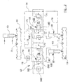
- the engine E drives the wheels 16, 20 of the machine 10 via a mechanical or hydrostatic or other transmission 38, and a machine ground speed sensor 39 senses movement of part of the transmission 38, such as the rotation of a gear wheel or drive shaft, the speed sensor 39 in use providing an input signal to a controller 40 which is indicative of machine ground speed, which signal is used by the controller 40 to control the operation of a hydraulic system 42 of the machine 10 which will be more particularly described below with reference to figure 2 .
- the speed sensor 39 may for example be a Hall effect sensor.
- the machine 10 in this example further includes a pair of stabiliser arms 35, 36 one being provided at each side of the body 12, in this example at the front end 13 of the machine 10.
- the stabiliser arms 35, 36 are in use, lowered into engagement with the ground to stabilise the machine 10 during working operations as described below, and when not in use are raised into a stowed condition.
- the stabiliser arms 35, 36 are preferably raised and lowered by an auxiliary hydraulically operated service which includes respective hydraulic actuators.
- a manually operated stabiliser arm control lever 43 which when operated causes the stabiliser arms 35, 36 to be raised or lowered, there being in this example a stabiliser control lever movement sensor drive 44 to sense movements of the stabiliser arm control lever 43 from a rest position.
- a manually operable sway control lever 45 the purpose of which will be explained below, and there being a sway control lever movement sensor device 46 to sense movements of the sway control lever 45 from a neutral position.
- Each of the stabiliser arm control lever sensor 44 and the sway control lever sensor 46 upon sensing a movement from a neutral position of the respective control lever 43, 45, provides a signal to the controller 40.
- a sway actuator 50 which is in this example a double acting hydraulic actuator of the piston-in-cylinder kind.
- the sway actuator 50 may be extended or retracted to pivot the front axle 15 relative to the body 12, to change the attitude of the body 12 relative to the ground.
- the sway actuator 50 may be extended or retracted to level the body 12, to compensate for an unlevelled ground surface.
- the front axle 15 is rigid relative to the body 12, particularly when the machine 10 is travelling over the ground surface.
- the operator's ability to operate the sway may be prevented at other than very slow speeds and when the machine 10 is stationary.
- Each control actuator 55, 56 is again of the piston-in-cylinder kind and may be double acting as drawn or single acting.
- the cylinders of the control actuators 55, 56 at the non-annulus sides of the control actuators 55, 56, are interconnected via a hydraulic system 42 which includes a pair of control valves 58, 59, each control valve 58, 58 being provided in a respective hydraulic line 60, 61 which extends to and from the respective control actuators 55, 56.
- Each control valve 58, 59 is an electrically operated proportional valve, electrical operation being effected by the controller 40.
- Each control valve 58, 59 permits the substantially unrestricted flow of hydraulic fluid to the non-annulus side of the respective control actuators 55, 56 via a poppet 58a, 59a, but the flow of fluid from the non-annulus sides of the respective control actuators 55, 56 is controlled depending on the extent of opening of the control valves 58, 59 which depends on a control signal received from the controller 40.
- the control valves 58, 59 may each have a solenoid or other electrical actuator as shown at 58b, 59b.
- pivoting of the rear axle 18 relative to the body 12 may or may not be permitted.
- the controller 40 signals the respective valve solenoids 58b, 59b fully to open the control valves 58, 59 to allow the substantially free flow of fluid through the lines 60, 61.
- the rear axle 18 may pivot about its pivot axis B in response to irregularities in the ground surface as permitted by its mounting, with fluid flowing from one non-annulus control actuator 55, 56 piston side to the non-annulus piston side of the other control actuator 56, 55 depending upon which side of the axle 18 rises and lowers relative to the body 12.
- the machine body 12 may remain more level than if the rear axle 18 was rigidly mounted, despite ground surface irregularities.
- the controller 40 will respond to the signal from the speed sensor 39 by signalling the solenoid valves 58, 59 to close, for example by removing any electrical power to the solenoids 58b, 59b altogether, so that the control valves 58, 59 are closed by respective mechanical springs 58c, 59c.
- fluid will not be permitted to pass from either non-annulus sides of the control actuators 55, 56 to the other and the rear axle 18 will be locked relative to the body 12.
- the locked rear axle 18 will afford maximum stability.
- the controller 30 responds to the signal from the speed sensor 39 according to e.g. a programmed control regime, by allowing a restricted flow of fluid between the non-annulus sides of the control actuators 55, 56.
- the degree of restriction may be proportional to the machine 10 speed up to the threshold speed.
- This partial restriction to fluid flow is achieved as the controller 40 provides signals to the solenoids 58b, 59b of the control valves 58, 59 partially to open the valves 58, 59 against the springs 58c, 59c pressures, preferably in proportion to the machine speed signalled by the speed sensor 39.
- control valves 55, 56 are proportional valves, there is no sudden change between one discrete operating mode and another, but the degree of change in the amount of cushioning of the rear axle 18 movement as the machine 10 speeds up and slows down, is continuous.
- the stabiliser arms 35, 36 may be lowered by a further auxiliary hydraulically operated service. Movement of the stabiliser arm control lever 43 is sensed by the sensor 44 and an auxiliary signal is provided to the controller 40 which responds by relieving the restriction to fluid flow otherwise provided by the control valves 58, 59 in accordance with the control regime.
- the controller 40 responds to the auxiliary input from sensor device 44 by partially opening the control valves 58, 59 even though the machine 10 is stationary, the auxiliary input from the stabiliser arm sensor 44 thus overriding.
- control valves 58, 59 may be opened to restrict the fluid flow by about 50% as a result of the auxiliary input from sensor 44.
- control valves 58, 59 are proportional valves, this means that the valves 58, 59 need to be half opened against the forces of the respective closure springs 58c, 59c.
- the sway actuator control lever 45 movement sensor 46 will signal the controller 40.
- the controller 40 will respond by partially opening the control valves 58, 59, again by for example, 50% to relieve the restriction to fluid flow between the control actuators 55, 56, to permit cushioned rear axle 18 movements.
- auxiliary inputs from sensor devices 44 and 46 allows the rear wheels 20 to remain in contact with the ground as the machine 10 is levelled ready for performing working operations, using either or both of the stabiliser arms 35, 36 or the sway control actuator 50.
- control valves 58, 59 will be fully closed when the auxiliary input from one or both of the sensor devices 44, 46 is provided, particularly if the machine 10 is still slowly moving over the ground, in the generality, an auxiliary input has the effect of overriding the usual control regime to relieve the restriction to fluid flow which is otherwise imposed.
- sensor devices 44, 46 have been described as being provided to sense respective movements of parts of respective control structures, namely control lever 43, 45 movements.
- movement of another part of the control structure for either the sway actuator 50 or the stabiliser arm actuator(s) may provide the auxiliary input to the controller 40.
- the control structure for the sway actuator 50 includes a hydraulic control valve 79 of the kind having a spool 81 which moves in a valve housing 82, with an end of the spool 81 extending from the valve housing 82 to an external position.
- a control such as the control lever 45, or another control, which may be directly connected to the spool 81 or indirectly operationally connected to the spool 81 e.g. via a hydraulic servo or an electrical actuating circuit, the spool 81 will reach a position as shown in figure 4 .
- the spool has a groove 85 in the end of the spool 81 external to the valve housing 82, and in the example, the groove 85 is aligned with a detent 76 which may be urged by a resilient device such as a spring, or by gravity, towards the groove 85. If the detent 76 moves out of groove 85, this will cause a signal to the controller 40 to be provided by a signalling device 80 to which the detent 86 is coupled, to indicate that the sway actuator 50 is being operated, thus to provide the auxiliary input to the controller 40 which responds by relieving the restriction to fluid flow between the control actuators 55, 56 which otherwise the control regime would demand.
- a signalling device 80 to which the detent 86 is coupled
- operation of the auxiliary hydraulically operated service may otherwise at least partially relieve the restriction to fluid flow, by for example a part of a control structure which controls the auxiliary service moving to open a relief valve in a by-pass circuit, or directly acting on the control valves 58, 59, in each case so that the restriction to fluid flow between the control 55, 56 actuators is at least partially relieved.
- control actuators 55, 56 are double acting and the annulus sides of the cylinders are interconnected via a flow line 63, so that upon the control actuators 55, 56 being extended and retracted, under the control of the hydraulic system 42, fluid is exchanged between the annulus sides of the control actuators 55, 56.
- the control actuators 55, 56 may be single acting.
- each hydraulic line 60, 61 there is provided in each hydraulic line 60, 61, a respective one way relief valve 70, 71, which relief valves permit fluid flow between the non-annulus sides of the control actuators 55, 56 and a respective low pressure take-up line 73, 75 which each extend to a reservoir 74 for hydraulic fluid.
- the line 75 from the relief valve 71 to the reservoir 74 is also connected via line 76, to each of the annulus sides of the control actuators 55, 56.
- fluid may pass from a pressured supply 79, via a one way valve 78 into the hydraulic lines 60, 61 in which the control valves 58, 59 are provided. If the control valves 58, 59 are closed, the fluid may pass into the lines 60, 61 between the valves 58, 59 and control actuators 55, 56 via check valves 58d, 59d.
- control actuators 55, 56 are provided, one for each side of the rear axe 18, in another embodiment a single control actuator may be provided at one side of the pivot axis B, with fluid flow between the cylinder at one side of the piston and the cylinder at the other side of the piston being controlled by one or more control valves.
- each control actuator 55, 56 having in the respective hydraulic line 60, 61 its own control valve 58, 59
- fluid flow between the control actuators 55, 56 or between the one cylinder side and the other where a single control actuator is provided may be controlled by a single control valve.
- lowering or raising of the stabiliser arms 35, 36 is achieved with a manually operable control device being a control lever 43, but this may be achieved with a switch which not only provides for stabiliser movement but also for providing an auxiliary input indicative of stabiliser arm 35, 36 actuator, to the controller 40 such that a separate sensor as shown at 44 need not be required.
- a switch may be provided instead of the sway control lever 45 also so that again, a separate sway control movement sensor as indicated at 46 need not be provided.
- the invention has been described in relation to a loading machine 10, the invention is applicable to a multitude of different working machines.
- the rear axle 18 instead of the rear axle 18 being stabilised as described above, the front axle 15 and/or front and rear axles 15, 18, may be stabilised in the manner described for rear axle 18 in the example.
- controller 40 may not open the control valves 58, 59 in response to the signal from the speed sensor 39 in the event that a parking brake is operational, but subject to either auxiliary input or inputs which indicate stabiliser arm 35, 36 lower or raising, or sway actuator 50 operation.
- An auxiliary signal to the controller 40 to at least partially relieve restriction to fluid flow otherwise provided may be derived from any appropriate auxiliary service, as desired.
- the rear axle 18, or at least the axle movement of which is to be controlled by the hydraulic system 42 need not be pivoted relative to the body 12 as described, but the axle 18 may be suspended from the body 12 by suspension control links which permit up and down axle 18 movements relative to the body 12, differentially at either side of the machine 10.
- Dampers such as mechanical or gas springs, would be required to damp axle movements.
- hydraulic system 42 described may still control axle movements relative to the body 12 in substantially the same way as described for pivoted axle 18 of the illustrated embodiment.
- the other axle e.g. front axle 15
- the body 12 may be pivoted too, as described with reference to figure 2 , or suspended from, the body 12 as required although in the case of a suspended axle 15, 18, two control actuators 50; 55, 56, one at or towards each of the respective axle ends, would be required.
- the hydraulic system 42 is only operational to restrict fluid flow so as to prevent free axle movement as permitted by its mounting, below a threshold speed, in another example, in which the amount of fluid flow restriction may or may not be proportional to the machine 10 ground speed, the hydraulic system 42 may provide resistance to fluid flow by an amount depending on machine ground speed, over the entire machine ground speed range.
Landscapes
- Engineering & Computer Science (AREA)
- Mechanical Engineering (AREA)
- Transportation (AREA)
- Structural Engineering (AREA)
- Civil Engineering (AREA)
- Life Sciences & Earth Sciences (AREA)
- Geology (AREA)
- Chemical & Material Sciences (AREA)
- Combustion & Propulsion (AREA)
- Vehicle Body Suspensions (AREA)
- Operation Control Of Excavators (AREA)
- Fluid-Pressure Circuits (AREA)
Applications Claiming Priority (1)
| Application Number | Priority Date | Filing Date | Title |
|---|---|---|---|
| GB0714382A GB2451244B (en) | 2007-07-21 | 2007-07-21 | Working machine |
Publications (3)
| Publication Number | Publication Date |
|---|---|
| EP2022747A2 true EP2022747A2 (fr) | 2009-02-11 |
| EP2022747A3 EP2022747A3 (fr) | 2010-05-26 |
| EP2022747B1 EP2022747B1 (fr) | 2013-08-21 |
Family
ID=38512743
Family Applications (1)
| Application Number | Title | Priority Date | Filing Date |
|---|---|---|---|
| EP08160565.1A Active EP2022747B1 (fr) | 2007-07-21 | 2008-07-16 | Machine de travail |
Country Status (7)
| Country | Link |
|---|---|
| US (1) | US7963528B2 (fr) |
| EP (1) | EP2022747B1 (fr) |
| AU (1) | AU2008203225B2 (fr) |
| CA (1) | CA2638085C (fr) |
| ES (1) | ES2436286T3 (fr) |
| GB (2) | GB2451244B (fr) |
| RU (1) | RU2478559C2 (fr) |
Cited By (2)
| Publication number | Priority date | Publication date | Assignee | Title |
|---|---|---|---|---|
| WO2010133955A1 (fr) * | 2009-05-22 | 2010-11-25 | Valtra Oy Ab | Suspension de tracteur |
| CN106143587A (zh) * | 2016-08-18 | 2016-11-23 | 安徽泗州拖拉机制造有限公司 | 一种大马力拖拉机的转向控制装置及控制方法 |
Families Citing this family (9)
| Publication number | Priority date | Publication date | Assignee | Title |
|---|---|---|---|---|
| CN102039791B (zh) * | 2010-06-13 | 2012-07-25 | 中联重科股份有限公司 | 车身倾角调整单元、油气悬架机构以及流动式起重机 |
| KR20150063766A (ko) * | 2013-12-02 | 2015-06-10 | 주식회사 두산 | 지게차 |
| EP2899153B1 (fr) * | 2014-01-23 | 2016-11-16 | Iveco Magirus Ag | Véhicule utilitaire comprenant un système de levage et un moyen de stabilisation |
| GB2627134B (en) * | 2020-03-31 | 2024-12-11 | Bamford Excavators Ltd | A working machine with a stability controller |
| US11623493B2 (en) | 2020-11-04 | 2023-04-11 | Terex South Dakota, Inc. | Vehicle suspension system |
| US11623492B2 (en) * | 2020-11-04 | 2023-04-11 | Terex South Dakota, Inc. | Vehicle suspension system |
| CN116457223B (zh) * | 2020-11-04 | 2024-08-30 | 特雷克斯南达科他州有限公司 | 车辆悬架系统 |
| GB2614737B (en) * | 2022-01-17 | 2026-04-29 | J C Bamford Excavators Ltd | A Working Machine |
| US20260070390A1 (en) * | 2024-09-12 | 2026-03-12 | Terex South Dakota, Inc. | Vehicle suspension system |
Citations (2)
| Publication number | Priority date | Publication date | Assignee | Title |
|---|---|---|---|---|
| US6082742A (en) | 1997-06-11 | 2000-07-04 | Kabushiki Kaisha Toyoda Jidoshokki Seisakusho | Apparatus for controlling tilt of axle for industrial vehicle, and apparatus and method for estimating center of gravity for industrial vehicle |
| US6179304B1 (en) | 1997-12-02 | 2001-01-30 | Kabushiki Kaisha Toyoda Jidoshokki Seisakusho | Axle pivot control method and apparatus for industrial vehicle |
Family Cites Families (21)
| Publication number | Priority date | Publication date | Assignee | Title |
|---|---|---|---|---|
| AT283197B (de) * | 1968-04-18 | 1970-07-27 | Wagner Appbau Ernst | Hubstapler, Transportfahrzeug od.dgl. |
| GB1470500A (en) | 1972-12-19 | 1977-04-14 | Liner Concrete Machinery | Stabilising fork lift trucks and other vehicles |
| GB1528741A (en) * | 1974-10-12 | 1978-10-18 | Liner Concrete Machinery | Load handling vehicle |
| US4264014A (en) * | 1978-11-06 | 1981-04-28 | Caterpillar Tractor Co. | Lock out means for pivotal axle suspension cylinders |
| JPH082727B2 (ja) * | 1988-01-26 | 1996-01-17 | 日産自動車株式会社 | アクティブサスペンション用油圧回路 |
| US5104143A (en) * | 1989-09-27 | 1992-04-14 | Toyota Jidosha Kabushiki Kaisha | Vehicle suspension system with roll control variable according to vehicle speed |
| DE59003689D1 (de) | 1989-11-07 | 1994-01-13 | Daimler Benz Ag | Hydropneumatisches Federungssystem. |
| US5388857A (en) * | 1992-08-27 | 1995-02-14 | Badger Equipment Company | Operator controlled vehicle stabilizer |
| DE69531448T2 (de) * | 1994-02-25 | 2004-07-22 | Kinetic Ltd., Dunsborough | Hydraulische aufhängung mit unabhängiger regelung von nick- und rollbewegung |
| JPH0971117A (ja) * | 1995-09-07 | 1997-03-18 | Komatsu Ltd | 建設機械のサスペンション装置およびその制御方法 |
| JPH1044735A (ja) * | 1996-08-01 | 1998-02-17 | Komatsu Ltd | 掘削作業車両のサスペンション装置及びその制御方法 |
| JPH115419A (ja) * | 1997-06-18 | 1999-01-12 | Toyota Autom Loom Works Ltd | 産業車両の車体揺動制御装置 |
| JPH1137204A (ja) * | 1997-07-23 | 1999-02-12 | Toyota Autom Loom Works Ltd | 産業車両用揺動規制装置及び油圧シリンダ |
| GB0002154D0 (en) * | 2000-02-01 | 2000-03-22 | Bamford Excavators Ltd | Working apparatus |
| GB2365407B (en) * | 2000-05-25 | 2003-10-08 | Bamford Excavators Ltd | Hydraulic system for wheeled loader |
| FR2821295B1 (fr) * | 2001-02-27 | 2003-09-26 | Bennes Maupu | Dispositif de blocage d'un essieu flottant sur benne de gros tonnage |
| US7383906B2 (en) * | 2002-08-29 | 2008-06-10 | Jlg Industries, Inc. | Rotatable and telescopic work machine |
| US6802687B2 (en) * | 2002-12-18 | 2004-10-12 | Caterpillar Inc | Method for controlling a raise/extend function of a work machine |
| US20040120800A1 (en) * | 2002-12-18 | 2004-06-24 | Litchfield Simon C. | Method for controlling a raise/extend function of a work machine |
| DE102005039251A1 (de) * | 2005-08-19 | 2007-02-22 | Deere & Company, Moline | Ladegerät |
| US7779974B2 (en) * | 2005-08-22 | 2010-08-24 | Technology Investments Limited | Vehicle suspension spring system |
-
2007
- 2007-07-21 GB GB0714382A patent/GB2451244B/en not_active Expired - Fee Related
-
2008
- 2008-07-16 EP EP08160565.1A patent/EP2022747B1/fr active Active
- 2008-07-16 ES ES08160565T patent/ES2436286T3/es active Active
- 2008-07-17 US US12/175,152 patent/US7963528B2/en active Active
- 2008-07-17 GB GB0813048A patent/GB2451327B/en active Active
- 2008-07-18 CA CA2638085A patent/CA2638085C/fr active Active
- 2008-07-18 AU AU2008203225A patent/AU2008203225B2/en active Active
- 2008-07-21 RU RU2008129646/11A patent/RU2478559C2/ru active
Patent Citations (2)
| Publication number | Priority date | Publication date | Assignee | Title |
|---|---|---|---|---|
| US6082742A (en) | 1997-06-11 | 2000-07-04 | Kabushiki Kaisha Toyoda Jidoshokki Seisakusho | Apparatus for controlling tilt of axle for industrial vehicle, and apparatus and method for estimating center of gravity for industrial vehicle |
| US6179304B1 (en) | 1997-12-02 | 2001-01-30 | Kabushiki Kaisha Toyoda Jidoshokki Seisakusho | Axle pivot control method and apparatus for industrial vehicle |
Cited By (3)
| Publication number | Priority date | Publication date | Assignee | Title |
|---|---|---|---|---|
| WO2010133955A1 (fr) * | 2009-05-22 | 2010-11-25 | Valtra Oy Ab | Suspension de tracteur |
| CN106143587A (zh) * | 2016-08-18 | 2016-11-23 | 安徽泗州拖拉机制造有限公司 | 一种大马力拖拉机的转向控制装置及控制方法 |
| CN106143587B (zh) * | 2016-08-18 | 2019-08-06 | 安徽泗州拖拉机制造有限公司 | 一种大马力拖拉机的转向控制装置及控制方法 |
Also Published As
| Publication number | Publication date |
|---|---|
| RU2478559C2 (ru) | 2013-04-10 |
| US7963528B2 (en) | 2011-06-21 |
| EP2022747A3 (fr) | 2010-05-26 |
| GB0813048D0 (en) | 2008-08-20 |
| AU2008203225A1 (en) | 2009-02-05 |
| ES2436286T3 (es) | 2013-12-30 |
| US20090020965A1 (en) | 2009-01-22 |
| GB2451244B (en) | 2011-09-28 |
| GB2451327A (en) | 2009-01-28 |
| CA2638085C (fr) | 2014-02-18 |
| EP2022747B1 (fr) | 2013-08-21 |
| CA2638085A1 (fr) | 2009-01-21 |
| GB2451244A (en) | 2009-01-28 |
| AU2008203225B2 (en) | 2013-10-03 |
| RU2008129646A (ru) | 2010-01-27 |
| GB0714382D0 (en) | 2007-09-05 |
| GB2451327B (en) | 2011-09-28 |
Similar Documents
| Publication | Publication Date | Title |
|---|---|---|
| EP2022747B1 (fr) | Machine de travail | |
| CN203920504U (zh) | 具有故障安全功能的座椅悬架系统 | |
| JP6134263B2 (ja) | 油圧駆動システム | |
| US5195864A (en) | Hydraulic system for a wheel loader | |
| US4264014A (en) | Lock out means for pivotal axle suspension cylinders | |
| KR20120086288A (ko) | 작업 기계의 유압 시스템 | |
| JP2002179387A (ja) | 作業用車両の速度制御装置とその速度制御方法 | |
| CA2983901C (fr) | Systeme de commande de deplacement pour machine motrice | |
| CA2319659A1 (fr) | Suspension hydraulique antiroulis, pret a monter et procede relatif a des vehicules de manutention de charges | |
| US20130153320A1 (en) | Adaptive seat suspension system | |
| JP3162384B2 (ja) | 作業装置を備えた作業機械のための液圧装置 | |
| CN117999178A (zh) | 具有单独乘坐高度和阻尼控制的悬架系统 | |
| EP1532009B1 (fr) | Vehicule et son procede de commande | |
| EP1657213B1 (fr) | Réglage de niveau | |
| US12385224B2 (en) | Wheeled construction machine | |
| JP2003278706A (ja) | 作業車の駆動制御装置 | |
| JP2602114B2 (ja) | 車両のダイナミックダンパー | |
| US20250002301A1 (en) | Mobile crane | |
| JPH0513819Y2 (fr) | ||
| JP2025128643A (ja) | 油圧駆動装置及びこれを備えた作業機械 | |
| JP2005075510A (ja) | 高所作業車のレベリング装置 | |
| GB2609534A (en) | Systems and methods for hydro-pneumatic suspension and leveling circuit |
Legal Events
| Date | Code | Title | Description |
|---|---|---|---|
| PUAI | Public reference made under article 153(3) epc to a published international application that has entered the european phase |
Free format text: ORIGINAL CODE: 0009012 |
|
| AK | Designated contracting states |
Kind code of ref document: A2 Designated state(s): AT BE BG CH CY CZ DE DK EE ES FI FR GB GR HR HU IE IS IT LI LT LU LV MC MT NL NO PL PT RO SE SI SK TR |
|
| AX | Request for extension of the european patent |
Extension state: AL BA MK RS |
|
| PUAL | Search report despatched |
Free format text: ORIGINAL CODE: 0009013 |
|
| AK | Designated contracting states |
Kind code of ref document: A3 Designated state(s): AT BE BG CH CY CZ DE DK EE ES FI FR GB GR HR HU IE IS IT LI LT LU LV MC MT NL NO PL PT RO SE SI SK TR |
|
| AX | Request for extension of the european patent |
Extension state: AL BA MK RS |
|
| RIC1 | Information provided on ipc code assigned before grant |
Ipc: B66F 9/065 20060101AFI20081107BHEP Ipc: B66F 9/22 20060101ALI20100420BHEP Ipc: B60G 17/016 20060101ALI20100420BHEP |
|
| 17P | Request for examination filed |
Effective date: 20101104 |
|
| AKX | Designation fees paid |
Designated state(s): AT BE BG CH CY CZ DE DK EE ES FI FR GB GR HR HU IE IS IT LI LT LU LV MC MT NL NO PL PT RO SE SI SK TR |
|
| GRAP | Despatch of communication of intention to grant a patent |
Free format text: ORIGINAL CODE: EPIDOSNIGR1 |
|
| RIC1 | Information provided on ipc code assigned before grant |
Ipc: B66F 9/065 20060101AFI20121219BHEP Ipc: B60G 17/005 20060101ALI20121219BHEP Ipc: B60G 17/016 20060101ALI20121219BHEP Ipc: B60G 9/02 20060101ALI20121219BHEP Ipc: B66F 9/22 20060101ALI20121219BHEP |
|
| GRAS | Grant fee paid |
Free format text: ORIGINAL CODE: EPIDOSNIGR3 |
|
| GRAA | (expected) grant |
Free format text: ORIGINAL CODE: 0009210 |
|
| AK | Designated contracting states |
Kind code of ref document: B1 Designated state(s): AT BE BG CH CY CZ DE DK EE ES FI FR GB GR HR HU IE IS IT LI LT LU LV MC MT NL NO PL PT RO SE SI SK TR |
|
| REG | Reference to a national code |
Ref country code: GB Ref legal event code: FG4D |
|
| REG | Reference to a national code |
Ref country code: CH Ref legal event code: EP |
|
| REG | Reference to a national code |
Ref country code: AT Ref legal event code: REF Ref document number: 627950 Country of ref document: AT Kind code of ref document: T Effective date: 20130915 |
|
| REG | Reference to a national code |
Ref country code: IE Ref legal event code: FG4D |
|
| REG | Reference to a national code |
Ref country code: DE Ref legal event code: R096 Ref document number: 602008026908 Country of ref document: DE Effective date: 20131017 |
|
| REG | Reference to a national code |
Ref country code: ES Ref legal event code: FG2A Ref document number: 2436286 Country of ref document: ES Kind code of ref document: T3 Effective date: 20131230 |
|
| REG | Reference to a national code |
Ref country code: NL Ref legal event code: VDEP Effective date: 20130821 Ref country code: AT Ref legal event code: MK05 Ref document number: 627950 Country of ref document: AT Kind code of ref document: T Effective date: 20130821 |
|
| REG | Reference to a national code |
Ref country code: LT Ref legal event code: MG4D |
|
| PG25 | Lapsed in a contracting state [announced via postgrant information from national office to epo] |
Ref country code: HR Free format text: LAPSE BECAUSE OF FAILURE TO SUBMIT A TRANSLATION OF THE DESCRIPTION OR TO PAY THE FEE WITHIN THE PRESCRIBED TIME-LIMIT Effective date: 20130821 Ref country code: NO Free format text: LAPSE BECAUSE OF FAILURE TO SUBMIT A TRANSLATION OF THE DESCRIPTION OR TO PAY THE FEE WITHIN THE PRESCRIBED TIME-LIMIT Effective date: 20131121 Ref country code: AT Free format text: LAPSE BECAUSE OF FAILURE TO SUBMIT A TRANSLATION OF THE DESCRIPTION OR TO PAY THE FEE WITHIN THE PRESCRIBED TIME-LIMIT Effective date: 20130821 Ref country code: PT Free format text: LAPSE BECAUSE OF FAILURE TO SUBMIT A TRANSLATION OF THE DESCRIPTION OR TO PAY THE FEE WITHIN THE PRESCRIBED TIME-LIMIT Effective date: 20131223 Ref country code: IS Free format text: LAPSE BECAUSE OF FAILURE TO SUBMIT A TRANSLATION OF THE DESCRIPTION OR TO PAY THE FEE WITHIN THE PRESCRIBED TIME-LIMIT Effective date: 20131221 Ref country code: CY Free format text: LAPSE BECAUSE OF FAILURE TO SUBMIT A TRANSLATION OF THE DESCRIPTION OR TO PAY THE FEE WITHIN THE PRESCRIBED TIME-LIMIT Effective date: 20130724 Ref country code: LT Free format text: LAPSE BECAUSE OF FAILURE TO SUBMIT A TRANSLATION OF THE DESCRIPTION OR TO PAY THE FEE WITHIN THE PRESCRIBED TIME-LIMIT Effective date: 20130821 Ref country code: SE Free format text: LAPSE BECAUSE OF FAILURE TO SUBMIT A TRANSLATION OF THE DESCRIPTION OR TO PAY THE FEE WITHIN THE PRESCRIBED TIME-LIMIT Effective date: 20130821 |
|
| PG25 | Lapsed in a contracting state [announced via postgrant information from national office to epo] |
Ref country code: BE Free format text: LAPSE BECAUSE OF FAILURE TO SUBMIT A TRANSLATION OF THE DESCRIPTION OR TO PAY THE FEE WITHIN THE PRESCRIBED TIME-LIMIT Effective date: 20130821 Ref country code: SI Free format text: LAPSE BECAUSE OF FAILURE TO SUBMIT A TRANSLATION OF THE DESCRIPTION OR TO PAY THE FEE WITHIN THE PRESCRIBED TIME-LIMIT Effective date: 20130821 Ref country code: PL Free format text: LAPSE BECAUSE OF FAILURE TO SUBMIT A TRANSLATION OF THE DESCRIPTION OR TO PAY THE FEE WITHIN THE PRESCRIBED TIME-LIMIT Effective date: 20130821 Ref country code: FI Free format text: LAPSE BECAUSE OF FAILURE TO SUBMIT A TRANSLATION OF THE DESCRIPTION OR TO PAY THE FEE WITHIN THE PRESCRIBED TIME-LIMIT Effective date: 20130821 Ref country code: GR Free format text: LAPSE BECAUSE OF FAILURE TO SUBMIT A TRANSLATION OF THE DESCRIPTION OR TO PAY THE FEE WITHIN THE PRESCRIBED TIME-LIMIT Effective date: 20131122 Ref country code: LV Free format text: LAPSE BECAUSE OF FAILURE TO SUBMIT A TRANSLATION OF THE DESCRIPTION OR TO PAY THE FEE WITHIN THE PRESCRIBED TIME-LIMIT Effective date: 20130821 |
|
| PG25 | Lapsed in a contracting state [announced via postgrant information from national office to epo] |
Ref country code: CY Free format text: LAPSE BECAUSE OF FAILURE TO SUBMIT A TRANSLATION OF THE DESCRIPTION OR TO PAY THE FEE WITHIN THE PRESCRIBED TIME-LIMIT Effective date: 20130821 |
|
| PG25 | Lapsed in a contracting state [announced via postgrant information from national office to epo] |
Ref country code: SK Free format text: LAPSE BECAUSE OF FAILURE TO SUBMIT A TRANSLATION OF THE DESCRIPTION OR TO PAY THE FEE WITHIN THE PRESCRIBED TIME-LIMIT Effective date: 20130821 Ref country code: EE Free format text: LAPSE BECAUSE OF FAILURE TO SUBMIT A TRANSLATION OF THE DESCRIPTION OR TO PAY THE FEE WITHIN THE PRESCRIBED TIME-LIMIT Effective date: 20130821 Ref country code: DK Free format text: LAPSE BECAUSE OF FAILURE TO SUBMIT A TRANSLATION OF THE DESCRIPTION OR TO PAY THE FEE WITHIN THE PRESCRIBED TIME-LIMIT Effective date: 20130821 Ref country code: RO Free format text: LAPSE BECAUSE OF FAILURE TO SUBMIT A TRANSLATION OF THE DESCRIPTION OR TO PAY THE FEE WITHIN THE PRESCRIBED TIME-LIMIT Effective date: 20130821 Ref country code: NL Free format text: LAPSE BECAUSE OF FAILURE TO SUBMIT A TRANSLATION OF THE DESCRIPTION OR TO PAY THE FEE WITHIN THE PRESCRIBED TIME-LIMIT Effective date: 20130821 Ref country code: CZ Free format text: LAPSE BECAUSE OF FAILURE TO SUBMIT A TRANSLATION OF THE DESCRIPTION OR TO PAY THE FEE WITHIN THE PRESCRIBED TIME-LIMIT Effective date: 20130821 |
|
| REG | Reference to a national code |
Ref country code: DE Ref legal event code: R082 Ref document number: 602008026908 Country of ref document: DE Representative=s name: TETZNER & PARTNER MBB PATENT- UND RECHTSANWAEL, DE |
|
| REG | Reference to a national code |
Ref country code: DE Ref legal event code: R097 Ref document number: 602008026908 Country of ref document: DE |
|
| PLBE | No opposition filed within time limit |
Free format text: ORIGINAL CODE: 0009261 |
|
| STAA | Information on the status of an ep patent application or granted ep patent |
Free format text: STATUS: NO OPPOSITION FILED WITHIN TIME LIMIT |
|
| 26N | No opposition filed |
Effective date: 20140522 |
|
| REG | Reference to a national code |
Ref country code: DE Ref legal event code: R097 Ref document number: 602008026908 Country of ref document: DE Effective date: 20140522 |
|
| PG25 | Lapsed in a contracting state [announced via postgrant information from national office to epo] |
Ref country code: LU Free format text: LAPSE BECAUSE OF FAILURE TO SUBMIT A TRANSLATION OF THE DESCRIPTION OR TO PAY THE FEE WITHIN THE PRESCRIBED TIME-LIMIT Effective date: 20140716 |
|
| REG | Reference to a national code |
Ref country code: CH Ref legal event code: PL |
|
| REG | Reference to a national code |
Ref country code: IE Ref legal event code: MM4A |
|
| PG25 | Lapsed in a contracting state [announced via postgrant information from national office to epo] |
Ref country code: CH Free format text: LAPSE BECAUSE OF NON-PAYMENT OF DUE FEES Effective date: 20140731 Ref country code: LI Free format text: LAPSE BECAUSE OF NON-PAYMENT OF DUE FEES Effective date: 20140731 |
|
| PG25 | Lapsed in a contracting state [announced via postgrant information from national office to epo] |
Ref country code: IE Free format text: LAPSE BECAUSE OF NON-PAYMENT OF DUE FEES Effective date: 20140716 |
|
| PG25 | Lapsed in a contracting state [announced via postgrant information from national office to epo] |
Ref country code: MC Free format text: LAPSE BECAUSE OF FAILURE TO SUBMIT A TRANSLATION OF THE DESCRIPTION OR TO PAY THE FEE WITHIN THE PRESCRIBED TIME-LIMIT Effective date: 20130821 |
|
| PG25 | Lapsed in a contracting state [announced via postgrant information from national office to epo] |
Ref country code: BG Free format text: LAPSE BECAUSE OF FAILURE TO SUBMIT A TRANSLATION OF THE DESCRIPTION OR TO PAY THE FEE WITHIN THE PRESCRIBED TIME-LIMIT Effective date: 20130821 |
|
| PG25 | Lapsed in a contracting state [announced via postgrant information from national office to epo] |
Ref country code: MT Free format text: LAPSE BECAUSE OF FAILURE TO SUBMIT A TRANSLATION OF THE DESCRIPTION OR TO PAY THE FEE WITHIN THE PRESCRIBED TIME-LIMIT Effective date: 20130821 |
|
| REG | Reference to a national code |
Ref country code: FR Ref legal event code: PLFP Year of fee payment: 9 |
|
| PG25 | Lapsed in a contracting state [announced via postgrant information from national office to epo] |
Ref country code: TR Free format text: LAPSE BECAUSE OF FAILURE TO SUBMIT A TRANSLATION OF THE DESCRIPTION OR TO PAY THE FEE WITHIN THE PRESCRIBED TIME-LIMIT Effective date: 20130821 Ref country code: HU Free format text: LAPSE BECAUSE OF FAILURE TO SUBMIT A TRANSLATION OF THE DESCRIPTION OR TO PAY THE FEE WITHIN THE PRESCRIBED TIME-LIMIT; INVALID AB INITIO Effective date: 20080716 |
|
| REG | Reference to a national code |
Ref country code: FR Ref legal event code: PLFP Year of fee payment: 10 |
|
| REG | Reference to a national code |
Ref country code: FR Ref legal event code: PLFP Year of fee payment: 11 |
|
| P01 | Opt-out of the competence of the unified patent court (upc) registered |
Effective date: 20230522 |
|
| PGFP | Annual fee paid to national office [announced via postgrant information from national office to epo] |
Ref country code: ES Payment date: 20250826 Year of fee payment: 18 |
|
| PGFP | Annual fee paid to national office [announced via postgrant information from national office to epo] |
Ref country code: DE Payment date: 20250722 Year of fee payment: 18 |
|
| PGFP | Annual fee paid to national office [announced via postgrant information from national office to epo] |
Ref country code: IT Payment date: 20250721 Year of fee payment: 18 |
|
| PGFP | Annual fee paid to national office [announced via postgrant information from national office to epo] |
Ref country code: GB Payment date: 20250716 Year of fee payment: 18 |
|
| PGFP | Annual fee paid to national office [announced via postgrant information from national office to epo] |
Ref country code: FR Payment date: 20250724 Year of fee payment: 18 |