EP2025045B1 - Système d'antenne à réseau de puce et de lentille - Google Patents
Système d'antenne à réseau de puce et de lentille Download PDFInfo
- Publication number
- EP2025045B1 EP2025045B1 EP06824417A EP06824417A EP2025045B1 EP 2025045 B1 EP2025045 B1 EP 2025045B1 EP 06824417 A EP06824417 A EP 06824417A EP 06824417 A EP06824417 A EP 06824417A EP 2025045 B1 EP2025045 B1 EP 2025045B1
- Authority
- EP
- European Patent Office
- Prior art keywords
- millimeter
- wave
- chip
- lens
- array antenna
- Prior art date
- Legal status (The legal status is an assumption and is not a legal conclusion. Google has not performed a legal analysis and makes no representation as to the accuracy of the status listed.)
- Expired - Lifetime
Links
Images



Classifications
-
- H—ELECTRICITY
- H01—ELECTRIC ELEMENTS
- H01Q—ANTENNAS, i.e. RADIO AERIALS
- H01Q15/00—Devices for reflection, refraction, diffraction or polarisation of waves radiated from an antenna, e.g. quasi-optical devices
- H01Q15/14—Reflecting surfaces; Equivalent structures
- H01Q15/148—Reflecting surfaces; Equivalent structures with means for varying the reflecting properties
-
- H—ELECTRICITY
- H01—ELECTRIC ELEMENTS
- H01Q—ANTENNAS, i.e. RADIO AERIALS
- H01Q1/00—Details of, or arrangements associated with, antennas
- H01Q1/007—Details of, or arrangements associated with, antennas specially adapted for indoor communication
-
- H—ELECTRICITY
- H01—ELECTRIC ELEMENTS
- H01Q—ANTENNAS, i.e. RADIO AERIALS
- H01Q19/00—Combinations of primary active antenna elements and units with secondary devices, e.g. with quasi-optical devices, for giving the antenna a desired directional characteristic
- H01Q19/06—Combinations of primary active antenna elements and units with secondary devices, e.g. with quasi-optical devices, for giving the antenna a desired directional characteristic using refracting or diffracting devices, e.g. lens
- H01Q19/062—Combinations of primary active antenna elements and units with secondary devices, e.g. with quasi-optical devices, for giving the antenna a desired directional characteristic using refracting or diffracting devices, e.g. lens for focusing
-
- H—ELECTRICITY
- H01—ELECTRIC ELEMENTS
- H01Q—ANTENNAS, i.e. RADIO AERIALS
- H01Q19/00—Combinations of primary active antenna elements and units with secondary devices, e.g. with quasi-optical devices, for giving the antenna a desired directional characteristic
- H01Q19/10—Combinations of primary active antenna elements and units with secondary devices, e.g. with quasi-optical devices, for giving the antenna a desired directional characteristic using reflecting surfaces
- H01Q19/12—Combinations of primary active antenna elements and units with secondary devices, e.g. with quasi-optical devices, for giving the antenna a desired directional characteristic using reflecting surfaces wherein the surfaces are concave
- H01Q19/17—Combinations of primary active antenna elements and units with secondary devices, e.g. with quasi-optical devices, for giving the antenna a desired directional characteristic using reflecting surfaces wherein the surfaces are concave the primary radiating source comprising two or more radiating elements
-
- H—ELECTRICITY
- H01—ELECTRIC ELEMENTS
- H01Q—ANTENNAS, i.e. RADIO AERIALS
- H01Q21/00—Antenna arrays or systems
- H01Q21/0006—Particular feeding systems
- H01Q21/0031—Parallel-plate fed arrays; Lens-fed arrays
-
- H—ELECTRICITY
- H01—ELECTRIC ELEMENTS
- H01Q—ANTENNAS, i.e. RADIO AERIALS
- H01Q3/00—Arrangements for changing or varying the orientation or the shape of the directional pattern of the waves radiated from an antenna or antenna system
- H01Q3/26—Arrangements for changing or varying the orientation or the shape of the directional pattern of the waves radiated from an antenna or antenna system varying the relative phase or relative amplitude of energisation between two or more active radiating elements; varying the distribution of energy across a radiating aperture
-
- H—ELECTRICITY
- H01—ELECTRIC ELEMENTS
- H01Q—ANTENNAS, i.e. RADIO AERIALS
- H01Q3/00—Arrangements for changing or varying the orientation or the shape of the directional pattern of the waves radiated from an antenna or antenna system
- H01Q3/26—Arrangements for changing or varying the orientation or the shape of the directional pattern of the waves radiated from an antenna or antenna system varying the relative phase or relative amplitude of energisation between two or more active radiating elements; varying the distribution of energy across a radiating aperture
- H01Q3/2658—Phased-array fed focussing structure
-
- H—ELECTRICITY
- H01—ELECTRIC ELEMENTS
- H01Q—ANTENNAS, i.e. RADIO AERIALS
- H01Q3/00—Arrangements for changing or varying the orientation or the shape of the directional pattern of the waves radiated from an antenna or antenna system
- H01Q3/26—Arrangements for changing or varying the orientation or the shape of the directional pattern of the waves radiated from an antenna or antenna system varying the relative phase or relative amplitude of energisation between two or more active radiating elements; varying the distribution of energy across a radiating aperture
- H01Q3/2664—Arrangements for changing or varying the orientation or the shape of the directional pattern of the waves radiated from an antenna or antenna system varying the relative phase or relative amplitude of energisation between two or more active radiating elements; varying the distribution of energy across a radiating aperture electrically moving the phase centre of a radiating element in the focal plane of a focussing device
-
- H—ELECTRICITY
- H01—ELECTRIC ELEMENTS
- H01Q—ANTENNAS, i.e. RADIO AERIALS
- H01Q3/00—Arrangements for changing or varying the orientation or the shape of the directional pattern of the waves radiated from an antenna or antenna system
- H01Q3/26—Arrangements for changing or varying the orientation or the shape of the directional pattern of the waves radiated from an antenna or antenna system varying the relative phase or relative amplitude of energisation between two or more active radiating elements; varying the distribution of energy across a radiating aperture
- H01Q3/30—Arrangements for changing or varying the orientation or the shape of the directional pattern of the waves radiated from an antenna or antenna system varying the relative phase or relative amplitude of energisation between two or more active radiating elements; varying the distribution of energy across a radiating aperture varying the relative phase between the radiating elements of an array
Definitions
- Some embodiments of the present invention pertain to wireless communication systems that use millimeter-wave signals. Some embodiments relate to antenna systems.
- the millimeter-wave band may have available spectrum and may be capable of providing higher throughput levels.
- compact directional millimeter-wave antennas and antenna systems suitable for use in wireless communication networks.
- compact directional millimeter-wave antennas and antenna systems that may improve the throughput of wireless networks.
- EP 0 212 963 discloses an azimuthally omni-directional antenna for radio waves which comprises a dielectric lens having an elliptical surface in a vertical plane and a reflector arrangement.
- EP 1 085 599 discloses a miniature phased array antenna system which includes a substrate having a high dielectric constant.
- Embodiments of the invention may be referred to herein, individually or collectively, by the term "invention" merely for convenience.
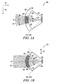
- FIGs. 1A and 1B illustrate a chip-lens array antenna system in accordance with some examples.
- Chip-lens array antenna system 100 comprises chip-array antenna 102 and millimeter-wave lens 104.
- FIG. 1A may illustrate a top-view of chip-lens array antenna system 100 and
- FIG. 1B may illustrate a side-view of chip-lens array antenna system 100.
- Chip-lens array antenna system 100 may generate diverging beam 110 in first plane 115 and may generate substantially non-diverging beam 112 in second plane 117.
- Chip-array antenna 102 generates and directs an incident beam of millimeter-wave signals through millimeter-wave lens 104 for subsequent transmission to user devices.
- Millimeter-wave lens 104 has inner surface 106 and outer surface 108 with curvatures selected to provide diverging beam 110 in first plane 115 and substantially non-diverging beam 112 in second plane 117.
- the incident beam of millimeter-wave signals directed by chip-array antenna 102 may be viewed as being squeezed in second plane 117 and may remain unchanged in first plane 115.
- inner surface 106 may be defined by substantially circular arc 126 in first plane 115 and substantially circular arc 136 in second plane 117.
- outer surface 108 may be defined by substantially circular arc 128 in first plane 115 and by elliptical arc 138 in second plane 117.
- inner surface 106 when defined by a substantially circular arc in both first plane 115 and second plane 117, may comprise a substantially spherical inner surface.
- first plane 115 may be a horizontal plane
- second plane 117 may be a vertical plane
- diverging beam 110 may be a fan-shaped beam in the horizontal plane.
- chip-array antenna 102 may generate wider incident beam 103 in the vertical plane and narrower incident beam 113 in the horizontal plane for incidence on inner surface 106 of millimeter-wave lens 104. Wider incident beam 103 may be converted to substantially non-diverging beam 112 by millimeter-wave lens 104, and narrower incident beam 113 may be converted to diverging beam 110 by millimeter-wave lens 104.
- diverging beam 110 and narrower incident beam 113 may have approximately equal beamwidths when outer surface 108 is defined by substantially circular arc 128 in first plane 115.
- wider incident beam 103 in vertical plane 117 may have a beamwidth of sixty degrees as illustrated in FIG. 1B
- narrower incident beam 113 in horizontal plane 115 may have a beamwidth of thirty degrees as illustrated in FIG.. 1A .
- wider incident beam 103, and narrower incident beam 113 may both be diverging beams.
- millimeter-wave lens 104 may have little or no effect on narrower incident beam 113, shown as having a beamwidth of thirty degrees, to provide diverging beam 110, which may also have a beamwidth of thirty degrees.
- millimeter-wave lens 104 may convert wider incident beam 103 to substantially non-diverging beam 112.
- the beamwidths of wider incident beam 103 and narrower incident beam 113 may refer to the scanning angles over which chip-lens array antenna 102 may direct an incident beam to millimeter-wave lens 104. These examples may provide for a wide-angle scanning capability in the horizontal plane. The scanning angle and the beamwidth in the horizontal plane may both be determined by the dimensions of chip-array antenna 102, whereas the beamwidth in the vertical plane may be primarily determined by the vertical aperture size of millimeter-wave lens 104.
- chip-lens antenna 102 may scan or steer an incident beam within millimeter-wave lens 104 to scan or steer beams 110 and 112 outside of millimeter-wave lens 104.
- anti-reflective layer 107 may be disposed on inner surface 106 of millimeter-wave lens 104 to help reduce reflections of incident millimeter-wave signals transmitted by chip-array antenna 102.
- anti-reflective layer 107 may be a layer of millimeter-wave transparent material comprising a material that is different than the material of millimeter-wave lens 104.
- the thickness of anti-reflective layer 107 may be selected so that millimeter-waves reflected from an incident surface of anti-reflective layer 107 and the millimeter-waves reflected from inner surface 106 (i.e., behind anti-reflective layer 107) may substantially cancel eliminating most or all reflected emissions.
- thickness of anti-reflective layer 107 may be about a quarter-wavelength when the refraction index of anti-reflective layer 107 is between that of millimeter-wave lens 104 and the air,
- the thickness of anti-reflective layer 107 may be much greater than a wavelength.
- one or more anti-reflective layers may be used to further suppress reflections.
- an anti-reflective layer or anti-reflective coating may be disposed on outer surface 108.
- anti-reflective layer 107 may comprise an anti-reflective coating.
- the use of anti-reflective layer 107 may reduce the input reflection coefficient so that when chip-lens array antenna system 100 is transmitting, any feedback as a result of reflections back to chip-array antenna 102 is reduced. This may help to avoid an undesirable excitation of the elements of chip-array antenna 102. The reduced feedback may also help improve the efficiency of chip-lens antenna system 100.
- chip-array antenna 102 comprises either a linear (i.e., one-dimensional) or planar (i.e., two-dimensional) array of individual antenna elements coupled to a radio-frequency (RF) signal path through control elements.
- the control elements may be used to control the amplitude and/or the phase shift between elements for steering the incident beam within the millimeter-wave lens.
- the control elements may set the amplitude and/or the phase shift for the antenna elements (e.g., to achieve a desired scanning angle).
- the rows of antenna elements may be controlled individually to direct the antenna beam.
- a linear phase-shift may be provided across the rows of the antenna elements.
- an array-excitation function may be applied to the antenna elements of chip-array antenna 102 to achieve certain characteristics of the antenna beam, such as a particular power profile and/or side-lobe levels. For example, a uniform amplitude distribution across the array of antenna elements with linear phase shifts in the horizontal directional and with a constant phase in the vertical direction may be used to help achieve some of the characteristics of beams 110 and 112. In some other examples, a Dolf-Chebyshev distribution or Gaussian power profile may be used for the amplitude and/or phase shifts across the antenna elements of chip-array antenna 102.
- Controlling the amplitude and/or phase difference between the antenna elements of chip-array antenna 102 may steer or direct the beams within a desired coverage area. It should be noted that the shape of millimeter-wave lens 104 provides for the characteristics of beams 110 and 112, while controlling and changing the amplitude and/or phase difference between the antenna elements may steer and direct the beams.
- the antenna elements of chip-array antenna 102 may comprise dipole radiating elements as other types of radiating elements may also be suitable.
- the antenna elements of chip-array antenna 102 may be configured in any one of a variety of shapes and/or configurations including square, rectangular, curved, straight, circular, or elliptical shapes.
- millimeter-wave lens 104 may be spaced apart from chip-array antenna 102 to provide cavity 105 therebetween.
- cavity 105 may be air filled or filled with an inert gas.
- cavity 105 may comprise a dielectric material having a higher permittivity and/or higher index of refraction at millimeter-wave frequencies than millimeter-wave lens 104. Due to the lower permittivity and/or lower index of refraction of the dielectric material that may be within cavity 105 less millimeter-wave reflections from inner surface 106 may result. In these examples, one or more foci may be implemented to help provide multiple antenna sectors.
- millimeter-wave lens 104 may be made of a solid millimeter-wave dielectric material, such as a millimeter-wave refractive material having a relative permittivity ranging between 2 and 3 for a predetermined millimeter-wave frequency.
- a solid millimeter-wave dielectric material such as a millimeter-wave refractive material having a relative permittivity ranging between 2 and 3 for a predetermined millimeter-wave frequency.
- cross-linked polymers such as Rexolite
- Rexolite may be used for the millimeter-wave refractive material, although other polymers and dielectric materials, such as polyethylene, poly-4-methylpentene-1, Teflon, and high density polyethylene, may also be used.
- Rexolite for example, may be available from C-LEC Plastics, Inc., Beverly, New Jersey, USA.
- gallium-arsenide GaAs, quartz, and/or acrylic glass may be used for millimeter-wave lens 104. Any of these materials may also be selected for anti-reflective layer 107 provided that it is a different material and has a higher index of refraction than the material used for millimeter-wave lens 104.
- millimeter-wave lens 104 and/or anti-reflective layer 107 may comprise artificial dielectric materials and may be implemented, for example, as a set of metallic plates or metallic particles distributed within a dielectric material.
- millimeter-wave lens 104 may comprise two or more layers of millimeter-wave dielectric material.
- the millimeter-wave dielectric material of a first layer closer to chip-array antenna 102 may have a higher permittivity than the millimeter-wave dielectric material of a second layer.
- the millimeter-wave signals transmitted and/or received by chip-lens antenna system 100 may comprise multicarrier signals having a plurality of substantially orthogonal subcarriers.
- the multicarrier signals may comprise orthogonal frequency division multiplexed (OFDM) signals
- the millimeter-wave signals may comprise millimeter-wave frequencies between approximately 60 and 90 Gigahertz (GHz).
- the millimeter-wave signals transmitted and/or received by chip-lens antenna system 100 may comprise single-carrier signals.
- FIGs. 2A and 2B illustrate a chip-lens array antenna system in accordance with some examples of the present invention.
- Chip-lens array antenna system 200 comprises chip-array antenna 202 and millimeter-wave lens 204.
- FIG. 2A may illustrate a top-view of chip-lens array antenna system 200 and
- FIG. 2B may illustrate a side-view of chip-lens array antenna system 200.
- Chip-lens array antenna system 200 may generate diverging beam 210 in first plane 215 and may generate substantially non-diverging beam 212 in second plane 217.
- outer surface 208 may be defined by elliptical arc 228 in first plane 215 and by elliptical arc 238 in second plane 217.
- Inner surface 206 may be defined by substantially circular arc 226 in first plane 215 and substantially circular arc 236 in second plane 217.
- diverging beam 210 may have a substantially narrower beamwidth than narrower incident beam 213 when outer surface 208 is defined by elliptical arc 228 in first plane 215.
- the incident beam of millimeter-wave signals directed by chip-array antenna 202 may be viewed as being squeezed in both second plane 217 and first plane 215, although the incident beam may be viewed as being squeezed less in first plane 215.
- chip-lens array antenna system 200 may provide a higher antenna gain with a smaller scanning angle in first plane 215 as compared to chip-lens array antenna system 100 ( FIGs. 1A and 1B ).
- wider incident beam 203 and narrower incident beam 213 may both be diverging beams.
- millimeter-wave lens 204 may convert narrower incident beam 213, shown as having a beamwidth of approximately thirty degrees, to diverging beam 210 of a substantially reduced beamwidth, shown as having a beamwidth of approximately fifteen degrees.
- millimeter-wave lens 204 may convert wider incident beam 203, shown as having a beamwidth of approximately sixty degrees, to substantially non-diverging beam 212.
- the selection of a particular elliptical arc in a particular plane may determine the beamwidth of a transmitted beam in that plane and whether the transmitted beam is diverging or non-diverging in that plane.
- wider incident beam 203 and narrower incident beam 213 may refer to the scanning angles over which chip-lens array antenna 202 may direct an incident beam to millimeter-wave lens 204.
- outer surface 208 may be defined by first elliptical arc 228 in first plane 215 and defined by a second elliptical arc 238 in second plane 217.
- first elliptical arc 228 may have a greater radius of curvature than second elliptical arc 238, and diverging beam 210 may be less diverging than incident beam 213 generated by chip-array antenna 202 in first plane 215 as a result of first elliptical arc 228 having a greater radius of curvature than second elliptical arc 238.
- Elliptical arcs with a greater radius of curvature may refer to ellipses having foci that have a greater separation to provide a 'flatter' elliptical arc.
- cavity 205 may be provided between millimeter-wave lens 204 and chip-array antenna 202. As discussed above in reference to chip-lens array antenna system 100 ( FIG. 1 ), cavity 205 may also be filled with either air or an inert gas, or alternatively, cavity 205 may comprise a dielectric material having a higher permittivity and/or higher index of refraction at millimeter-wave frequencies than millimeter-wave lens 204.
- millimeter-wave lens 204 may also comprise two or more layers of millimeter-wave dielectric material.
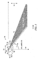
- FIG. 3 illustrates a chip-lens array antenna system in accordance with a secant-squared (sec 2 ) example.
- FIG. 3 illustrates a side-view of chip-lens array antenna system 300.
- Chip-lens array antenna system 300 comprises millimeter-wave lens 304 and chip-array antenna 302.
- Chip-array antenna 302 may generate and direct an incident beam of millimeter-wave signals through millimeter-wave lens 304 for subsequent transmission to user devices.
- millimeter-wave lens 304 may have substantially spherical inner surface 306 and may have outer surface 308 comprising first and second portions 318A and 318B.
- First and second portions 318A and 318B of outer surface 308 may be selected to provide a substantially omnidirectional pattern in first plane 315 and substantially secant-squared pattern 314 in second plane 317.
- inner surface 306 may be defined by substantially circular arc 336 in both horizontal plane 315 and vertical plane 317, and secant-squared pattern 314 may provide an antenna gain pattern that depends on elevation angle 303 to provide user devices with substantially uniform signal levels substantially independent of range.
- the curve of outer surface 308 may represent a solution to a differential equation and may have neither a spherical, an elliptical, nor a parabolic shape.
- the curve of outer surface 308 may be a generatrix curve in which a parameterization has been assigned based on the substantially secant-squared 314.
- millimeter-wave lens 304 may be symmetric with respect to vertical axis 301. In other words, the shape of millimeter-wave lens 304 may be obtained by revolving around vertical axis 301.
- first plane 315 may be a horizontal plane and second plane 317 may be a vertical plane.
- a substantially omnidirectional pattern in the horizontal plane and substantially secant-squared pattern 314 in the vertical plane may provide one or more user devices with approximately the same signal power level substantially independent of the distance from millimeter-wave lens 304 over a predetermined range.
- the substantially omnidirectional pattern in the horizontal plane and substantially secant-squared pattern 314 in the vertical plane may also provide one or more user devices with approximately the same antenna sensitivity for reception of signals substantially independent of the distance from millimeter-wave lens 304 over the predetermined range.
- user devices in the far illumination zone may be able to communicate just as well as user devices located in the near illumination zone.
- cavity 305 may be provided between millimeter-wave lens 304 and chip-array antenna 302. As discussed above in reference to chip-lens array antenna system 100 ( FIG. 1 ), cavity 305 may also be filled with either air or an inert gas, or alternatively, cavity 305 may comprise a dielectric material having a higher permittivity and/or higher index of refraction at millimeter-wave frequencies than millimeter-wave lens 304.
- millimeter-wave lens 304 may also comprise two or more layers of millimeter-wave dielectric material.
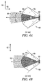
- FIGs. 4A and 4B illustrate a chip-lens array antenna system in accordance with some fully-filled examples.
- FIG. 4A may illustrate a top-view of chip-lens array antenna system 400 and
- FIG. 4B may illustrate a side-view of chip-lens array antenna system 400.
- chip-lens array antenna system 400 includes chip-array antenna 402 and millimeter-wave refractive material 404 disposed over chip-array antenna 402.
- Chip-array antenna 402 generates and directs a beam of millimeter-wave signals within millimeter-wave refractive material 404 for subsequent transmission to one or more user devices.
- millimeter-wave refractive material 404 has outer surface 408, which may be defined by either a substantially circular arc (not shown) or elliptical arc 428 in first plane 415, and elliptical arc 438 in second plane 417. This curvature may generate diverging beam 410 in first plane 415 and substantially non-diverging beam 412 in second plane 417.
- chip-array antenna 402 may be at least partially embedded within millimeter-wave refractive material 404.
- Chip-lens array antenna system 400 may require less space than chip-lens array antenna system 100 ( FIGs. 1A and 1B ) or chip-lens array antenna system 200 ( FIGs. 2A and 2B ) when configured to achieve similar characteristics and when similar lens material is used. In some examples, up to a three times reduction in size may be achieved.
- the size of chip-array antenna 402 may be proportionally reduced while the beamwidth within refractive material 404 may remain unchanged because the wavelength of the millimeter-wave signals may be shorter within refractive material 404 than, for example, in air. This may help reduce the cost of chip-lens array antenna system 400.
- the wavefront provided by chip-array antenna 402 may become more spherical and less distorted near outer surface 408.
- millimeter-wave refractive material 404 may reduce distortion caused by the non-zero size of chip-array antenna 402 providing a more predictable directivity pattern.
- the absence of reflections from an inner surface may reduce the input reflection coefficient reducing unfavorable feedback to chip-array antenna 402.
- a non-reflective coating or layer may be provided over outer surface 408 to reduce reflections.
- millimeter-wave dielectric material 404 may comprise two or more layers of millimeter-wave dielectric material, although the scope of the invention is not limited in this respect.
- FIG. 5 illustrates a chip-lens array antenna system in accordance with a multi-sector embodiment of the present invention.
- FIG. 5 illustrates a top-view of multi-sector chip-lens array antenna system 500.
- Multi-sector chip-lens array antenna system 500 comprises a plurality of millimeter-wave lens sections 504 and a plurality of chip-array antennas 502 to direct millimeter-wave signals through an associated one of millimeter-wave lens sections 504 for subsequent transmission to one or more user devices.
- each of millimeter-wave lens sections 504 comprises an inner surface 506 defined by arcs.
- Each of millimeter-wave lens sections 504 also has an outer surface 508 defined by either a substantially circular arc or an elliptical arc in first plane 515 and defined by an elliptical arc in a second plane.
- First plane 515 may be the horizontal plane and the second plane may be the vertical plane (i.e., perpendicular to or into the page).
- each chip-array antenna 502, and one of millimeter-wave lens sections 504 may be associated with one sector of a plurality of sectors for communicating with the user devices located within the associated sector.
- each sector may cover approximately sixty degrees of horizontal plane 515, and diverging beams 510 may have a fifteen-degree beamwidth in the horizontal plane.
- chip-array antenna 502 may steer its beam within a thirty-degree beamwidth within lens 504 for scanning within a sixty-degree sector as illustrated to provide full coverage within each sector.
- each sector may cover approximately 120 degrees.
- each of chip-array antennas 502 may illuminate millimeter-wave lens 504 with a thirty-degree beamwidth
- Millimeter-wave lens 504 may downscale the beamwidth, for example, by a factor of two, to provide diverging beams 510 with a beamwidth of fifteen degrees external to millimeter-wave lens 504. This downscaling of the beamwidth may allow chip-array antennas 502 to provide a greater-radius coverage area when scanning.
- chip-array antenna 522 may scan over scanning angle 524 (shown as ninety degrees) to cover a larger sector providing scanning angle 526 (shown as forty-five degrees) outside millimeter-wave lens 504 (i.e., from scanned beam 520 to scanned beam 521).
- a scanning angle of forty-five degrees outside millimeter-wave lens 504 may be downscaled from a ninety-degree scanning angle inside millimeter-wave lens 504. This may allow each chip-array antenna 502, to provide coverage over one of the sixty-degree sectors with a fifteen-degree beamwidth provided by each diverging beam 510.
- one or more cavities may be provided between millimeter-wave lens 504 and chip-array antennas 502. As discussed above in reference to chip-lens array antenna system 100 ( FIG. 1 ), these cavities may be filled with either air or an inert gas, or alternatively, these cavities may comprise a dielectric material having a higher permittivity and/or higher index of refraction at millimeter-wave frequencies than millimeter-wave lens 504.
- millimeter-wave lens 504 may also comprise two or more layers of millimeter-wave dielectric material.
- chip-array antenna 102 may be suitable for use as chip-array antenna 202, chip-array antenna 302, chip-array antenna 402, and chip-array antenna 502.
- the materials described above for use in fabricating millimeter-wave lens 104 may also be suitable for in fabricating millimeter-wave lens 204, millimeter-wave lens 304 millimeter-wave lens refractive material 404 and the sections of millimeter-wave lens 504.
- an anti-reflective layer or coating such as anti-reflective layer 107, may be provided over the inner and/or outer surfaces of millimeter-wave lens 204, the inner and/or outer surfaces millimeter-wave lens 304, the outer surface of millimeter-wave lens material 404 and the inner and/or outer surfaces of the sections of millimeter-wave lens 504.
- FIG. 6 illustrates a millimeter-wave communication system in accordance with an example.
- Millimeter-wave communication system 600 includes millimeter-wave multicarrier base station 604 and chip-lens array antenna system 602.
- Millimeter-wave multicarrier base station 604 may generate millimeter-wave signals for transmission by chip-lens array antenna system 602 to user devices.
- Chip-lens array antenna system 602 may also provide millimeter-wave signals received from user devices to millimeter-wave multicarrier base station 604.
- millimeter-wave multicarrier base station 604 may generate and/or process multicarrier millimeter-wave signals.
- Chip-lens array antenna system 100 ( FIGs. 1A and 1B ), chip-lens array antenna system 200 ( FIGs 2A and 2B ), chip-lens array antenna system 300 ( FIG. 3 ), chip-lens array antenna system 400 ( FIGs. 4A and 4B ), or chip-lens array antenna system 500 ( FIG. 5 ) may be suitable for use as chip-lens array antenna system 602.
- user devices may be a portable wireless communication device, such as a personal digital assistant (PDA), a laptop or portable computer with wireless communication capability, a web tablet, a wireless telephone, a wireless headset, a pager, an instant messaging device, a digital camera, an access point, a television, a medical device (e.g., a heart rate monitor, a blood pressure monitor, etc.), or other device that may receive and/or transmit information wirelessly.
- PDA personal digital assistant
- laptop or portable computer with wireless communication capability such as a web tablet, a wireless telephone, a wireless headset, a pager, an instant messaging device, a digital camera, an access point, a television, a medical device (e.g., a heart rate monitor, a blood pressure monitor, etc.), or other device that may receive and/or transmit information wirelessly.
- user devices may include a directional antenna to receive and/or transmit millimeter-wave signals.
- millimeter-wave communication system 600 may communicate millimeter-wave signals in accordance with specific communication standards or proposed specifications, such as the Institute of Electrical and Electronics Engineers (IEEE) standards including the IEEE 802.15 standards and proposed specifications for millimeter-wave communications (e.g., the IEEE 802.15 task group 3c 'Call For Intent' dated December 2005), although the system may also be suitable to transmit and/or receive communications in accordance with other techniques and standards.
- IEEE 802.15 standards please refer to "IEEE Standards for Information Technology - Telecommunications and Information Exchange between Systems" - Part 15.
Landscapes
- Physics & Mathematics (AREA)
- Electromagnetism (AREA)
- Aerials With Secondary Devices (AREA)
- Variable-Direction Aerials And Aerial Arrays (AREA)
- Mobile Radio Communication Systems (AREA)
- Radar Systems Or Details Thereof (AREA)
- Support Of Aerials (AREA)
Claims (5)
- Système d'antenne réseau à lentille à puce multisecteur (500) caractérisé par :une pluralité de sections de lentille à ondes millimétriques (504) ; etune pluralité d'antennes réseaux à puce (502) pour diriger les signaux à ondes millimétriques à travers l'une associée des sections de lentille à ondes millimétriques (504) pour une transmission subséquente,dans lequel chacune des sections de lentille à ondes millimétriques (504) comprend une surface intérieure (506) définie par des arcs partiellement circulaires, etdans lequel chacune des sections de lentille à ondes millimétriques a une surface extérieure (508) définie par un arc sensiblement circulaire ou par un arc elliptique sur le premier plan (515) et définie par un arc elliptique sur le second plan pour fournir un faisceau divergent sur le premier plan de chaque secteur et pour fournir un faisceau sensiblement non-divergent sur le second plan de chaque secteur.
- Système d'antenne réseau à lentille à puce multisecteur (500) selon la revendication 1, dans lequel chaque antenne réseau à puce (502) et section de lentille à ondes millimétriques (504) est associée à un secteur d'une pluralité de secteurs à des fins de communication, et
comprenant en outre une couche antireflet (107) disposée sur au moins l'une de la surface intérieure (506) ou de la surface extérieure (508) de la lentille à ondes millimétriques pour aider à réduire les réflexions des signaux à ondes millimétriques générés par l'antenne réseau à puce (502). - Système d'antenne réseau à lentille à puce multisecteur (500) selon la revendication 1, dans lequel chaque antenne réseau à puce (502) comprend un réseau linéaire ou planaire d'éléments d'antenne couplés à un chemin de signaux à ondes millimétriques par des éléments de contrôle, les éléments de contrôle contrôlant une amplitude et un déphasage entre les éléments d'antenne pour diriger le faisceau incident dans la lentille à ondes millimétriques,
dans laquelle la lentille à ondes millimétriques comprend un matériau réfractaire polymère réticulé, et
dans lequel les signaux à ondes millimétriques comprennent des signaux à ondes porteuses multiples ayant une pluralité de sous-porteuses sensiblement orthogonales comprenant des fréquences à ondes millimétriques entre environ 60 et 90 Gigahertz. - Système d'antenne réseau à lentille à puce multisecteur (500) selon la revendication 1, dans lequel la lentille à ondes millimétriques (504) est espacée de l'antenne réseau à puce (502) pour fournir une cavité entre elles, la cavité comprenant un matériau diélectrique ayant une plus grande permittivité que la lentille à ondes millimétriques.
- Système d'antenne réseau à lentille à puce multisecteur (500) selon la revendication 1, dans lequel la lentille à ondes millimétriques comprend au moins des première et seconde couches de matériau diélectrique à ondes millimétriques,
dans lequel le matériau diélectrique à ondes millimétriques de la première couche a une plus grande permittivité que le matériau diélectrique à ondes millimétriques de la seconde couche, et
dans lequel la première couche est plus proche de l'antenne réseau à puce que la seconde couche.
Applications Claiming Priority (1)
| Application Number | Priority Date | Filing Date | Title |
|---|---|---|---|
| PCT/RU2006/000256 WO2007136289A1 (fr) | 2006-05-23 | 2006-05-23 | Systèmes d'antennes à réseau de puces et de lentilles à ondes millimétriques pour réseaux sans fil |
Publications (2)
| Publication Number | Publication Date |
|---|---|
| EP2025045A1 EP2025045A1 (fr) | 2009-02-18 |
| EP2025045B1 true EP2025045B1 (fr) | 2011-05-11 |
Family
ID=37697865
Family Applications (3)
| Application Number | Title | Priority Date | Filing Date |
|---|---|---|---|
| EP06824417A Expired - Lifetime EP2025045B1 (fr) | 2006-05-23 | 2006-05-23 | Système d'antenne à réseau de puce et de lentille |
| EP06824430A Withdrawn EP2022135A1 (fr) | 2006-05-23 | 2006-06-16 | Systeme d'antenne a reflecteur d'ondes millimetriques et procedes de communication faisant appel a des signaux a ondes millimetriques |
| EP06835789A Not-in-force EP2022188B1 (fr) | 2006-05-23 | 2006-06-16 | Réseau personnel à ondes millimétriques |
Family Applications After (2)
| Application Number | Title | Priority Date | Filing Date |
|---|---|---|---|
| EP06824430A Withdrawn EP2022135A1 (fr) | 2006-05-23 | 2006-06-16 | Systeme d'antenne a reflecteur d'ondes millimetriques et procedes de communication faisant appel a des signaux a ondes millimetriques |
| EP06835789A Not-in-force EP2022188B1 (fr) | 2006-05-23 | 2006-06-16 | Réseau personnel à ondes millimétriques |
Country Status (6)
| Country | Link |
|---|---|
| US (3) | US8193994B2 (fr) |
| EP (3) | EP2025045B1 (fr) |
| JP (1) | JP2009538034A (fr) |
| CN (3) | CN101427422B (fr) |
| AT (2) | ATE509391T1 (fr) |
| WO (3) | WO2007136289A1 (fr) |
Families Citing this family (329)
| Publication number | Priority date | Publication date | Assignee | Title |
|---|---|---|---|---|
| US7193562B2 (en) | 2004-11-22 | 2007-03-20 | Ruckus Wireless, Inc. | Circuit board having a peripheral antenna apparatus with selectable antenna elements |
| US7292198B2 (en) | 2004-08-18 | 2007-11-06 | Ruckus Wireless, Inc. | System and method for an omnidirectional planar antenna apparatus with selectable elements |
| US7358912B1 (en) | 2005-06-24 | 2008-04-15 | Ruckus Wireless, Inc. | Coverage antenna apparatus with selectable horizontal and vertical polarization elements |
| US7893882B2 (en) | 2007-01-08 | 2011-02-22 | Ruckus Wireless, Inc. | Pattern shaping of RF emission patterns |
| EP2025045B1 (fr) | 2006-05-23 | 2011-05-11 | Intel Corporation | Système d'antenne à réseau de puce et de lentille |
| DE602006020785D1 (de) * | 2006-05-23 | 2011-04-28 | Intel Corp | Millimeterwellen-kommunikationssystem für den innenraum |
| US8320942B2 (en) * | 2006-06-13 | 2012-11-27 | Intel Corporation | Wireless device with directional antennas for use in millimeter-wave peer-to-peer networks and methods for adaptive beam steering |
| US8873585B2 (en) | 2006-12-19 | 2014-10-28 | Corning Optical Communications Wireless Ltd | Distributed antenna system for MIMO technologies |
| JP5305408B2 (ja) * | 2007-01-30 | 2013-10-02 | インテレクチュアル ディスカバリー シーオー エルティディ | 通信システムにおける信号の送受信方法及び装置 |
| US9312938B2 (en) | 2007-02-19 | 2016-04-12 | Corning Optical Communications Wireless Ltd | Method and system for improving uplink performance |
| US20100054746A1 (en) | 2007-07-24 | 2010-03-04 | Eric Raymond Logan | Multi-port accumulator for radio-over-fiber (RoF) wireless picocellular systems |
| US8175459B2 (en) | 2007-10-12 | 2012-05-08 | Corning Cable Systems Llc | Hybrid wireless/wired RoF transponder and hybrid RoF communication system using same |
| US8594133B2 (en) | 2007-10-22 | 2013-11-26 | Corning Mobileaccess Ltd. | Communication system using low bandwidth wires |
| US8175649B2 (en) | 2008-06-20 | 2012-05-08 | Corning Mobileaccess Ltd | Method and system for real time control of an active antenna over a distributed antenna system |
| WO2009081376A2 (fr) * | 2007-12-20 | 2009-07-02 | Mobileaccess Networks Ltd. | Extension de services et d'applications d'extérieur à des zones fermées |
| DE102008008715A1 (de) | 2008-02-11 | 2009-08-13 | Krohne Meßtechnik GmbH & Co KG | Dielektrische Antenne |
| US20090209216A1 (en) * | 2008-02-20 | 2009-08-20 | Sony Corporation | Reflector for wireless television transmissions |
| US8335203B2 (en) * | 2008-03-11 | 2012-12-18 | Intel Corporation | Systems and methods for polling for dynamic slot reservation |
| CN101662076B (zh) * | 2008-08-28 | 2012-11-28 | 阮树成 | 毫米波准光集成介质透镜天线及其阵列 |
| JP5556072B2 (ja) * | 2009-01-07 | 2014-07-23 | ソニー株式会社 | 半導体装置、その製造方法、ミリ波誘電体内伝送装置 |
| US9673904B2 (en) | 2009-02-03 | 2017-06-06 | Corning Optical Communications LLC | Optical fiber-based distributed antenna systems, components, and related methods for calibration thereof |
| WO2010091004A1 (fr) | 2009-02-03 | 2010-08-12 | Corning Cable Systems Llc | Systèmes et composants d'antennes distribuées à base de fibres optiques, et procédés de calibrage associés |
| AU2010210766A1 (en) | 2009-02-03 | 2011-09-15 | Corning Cable Systems Llc | Optical fiber-based distributed antenna systems, components, and related methods for monitoring and configuring thereof |
| JP5649588B2 (ja) | 2009-02-08 | 2015-01-07 | コーニング モバイルアクセス エルティディ. | イーサネット信号を搬送するケーブルを用いる通信システム |
| US8217843B2 (en) | 2009-03-13 | 2012-07-10 | Ruckus Wireless, Inc. | Adjustment of radiation patterns utilizing a position sensor |
| DE102010028881A1 (de) | 2009-06-03 | 2010-12-09 | Continental Teves Ag & Co. Ohg | Fahrzeugantennenvorrichtung mit horizontaler Hauptstrahlrichtung |
| US8264548B2 (en) * | 2009-06-23 | 2012-09-11 | Sony Corporation | Steering mirror for TV receiving high frequency wireless video |
| US9590733B2 (en) | 2009-07-24 | 2017-03-07 | Corning Optical Communications LLC | Location tracking using fiber optic array cables and related systems and methods |
| US8548330B2 (en) | 2009-07-31 | 2013-10-01 | Corning Cable Systems Llc | Sectorization in distributed antenna systems, and related components and methods |
| US20110109501A1 (en) * | 2009-11-06 | 2011-05-12 | Viasat, Inc. | Automated beam peaking satellite ground terminal |
| US8280259B2 (en) | 2009-11-13 | 2012-10-02 | Corning Cable Systems Llc | Radio-over-fiber (RoF) system for protocol-independent wired and/or wireless communication |
| JP5229915B2 (ja) * | 2009-12-10 | 2013-07-03 | シャープ株式会社 | ミリ波受信装置、ミリ波受信装置の取付構造およびミリ波送受信装置 |
| US9203149B2 (en) | 2010-02-15 | 2015-12-01 | Bae Systems Plc | Antenna system |
| US8275265B2 (en) | 2010-02-15 | 2012-09-25 | Corning Cable Systems Llc | Dynamic cell bonding (DCB) for radio-over-fiber (RoF)-based networks and communication systems and related methods |
| EP2360785A1 (fr) * | 2010-02-15 | 2011-08-24 | BAE SYSTEMS plc | Système d'antenne |
| CN102845001B (zh) | 2010-03-31 | 2016-07-06 | 康宁光缆系统有限责任公司 | 基于光纤的分布式通信组件及系统中的定位服务以及相关方法 |
| US9525488B2 (en) | 2010-05-02 | 2016-12-20 | Corning Optical Communications LLC | Digital data services and/or power distribution in optical fiber-based distributed communications systems providing digital data and radio frequency (RF) communications services, and related components and methods |
| US20110268446A1 (en) | 2010-05-02 | 2011-11-03 | Cune William P | Providing digital data services in optical fiber-based distributed radio frequency (rf) communications systems, and related components and methods |
| US8570914B2 (en) | 2010-08-09 | 2013-10-29 | Corning Cable Systems Llc | Apparatuses, systems, and methods for determining location of a mobile device(s) in a distributed antenna system(s) |
| EP2606707A1 (fr) | 2010-08-16 | 2013-06-26 | Corning Cable Systems LLC | Grappes d'antennes distantes, et systèmes, composants et procédés associés adaptés pour prendre en charge une propagation de signaux de données numériques entre des unités d'antennes distantes |
| JP2012078172A (ja) * | 2010-09-30 | 2012-04-19 | Panasonic Corp | 無線通信装置 |
| FR2965980B1 (fr) * | 2010-10-06 | 2013-06-28 | St Microelectronics Sa | Reseau d'antennes pour dispositif d'emission/reception de signaux de longueur d'onde du type micro-onde, millimetrique ou terahertz |
| US9252874B2 (en) | 2010-10-13 | 2016-02-02 | Ccs Technology, Inc | Power management for remote antenna units in distributed antenna systems |
| US9160449B2 (en) | 2010-10-13 | 2015-10-13 | Ccs Technology, Inc. | Local power management for remote antenna units in distributed antenna systems |
| US8816907B2 (en) * | 2010-11-08 | 2014-08-26 | Blinq Wireless Inc. | System and method for high performance beam forming with small antenna form factor |
| US11296504B2 (en) | 2010-11-24 | 2022-04-05 | Corning Optical Communications LLC | Power distribution module(s) capable of hot connection and/or disconnection for wireless communication systems, and related power units, components, and methods |
| EP2643947B1 (fr) | 2010-11-24 | 2018-09-19 | Corning Optical Communications LLC | Module(s) de distribution d'énergie électrique capable(s) d'une connexion et/ou déconnexion à chaud pour des systèmes d'antennes réparties, et unités d'énergie électrique, composants et procédés associés |
| WO2012090195A1 (fr) * | 2010-12-30 | 2012-07-05 | Beam Networks Ltd. | Réseau sans fil d'intérieur à répéteurs montés au plafond |
| US8797211B2 (en) | 2011-02-10 | 2014-08-05 | International Business Machines Corporation | Millimeter-wave communications using a reflector |
| CN203504582U (zh) | 2011-02-21 | 2014-03-26 | 康宁光缆系统有限责任公司 | 一种分布式天线系统及用于在其中分配电力的电源装置 |
| WO2012148938A1 (fr) | 2011-04-29 | 2012-11-01 | Corning Cable Systems Llc | Détermination de temps de propagation de communications dans systèmes d'antennes distribuées, et composants, systèmes et procédés associés |
| CN103609146B (zh) | 2011-04-29 | 2017-05-31 | 康宁光缆系统有限责任公司 | 用于增加分布式天线系统中的射频(rf)功率的系统、方法和装置 |
| WO2012161612A1 (fr) | 2011-05-23 | 2012-11-29 | Autonomous Non-Commercial Organization "Research Institute "Sitronics Labs"" | Dispositif d'antenne à faisceau orientable électroniquement |
| CN102956975B (zh) * | 2011-08-31 | 2015-07-01 | 深圳光启高等理工研究院 | 一种喇叭天线 |
| WO2013058673A1 (fr) * | 2011-10-20 | 2013-04-25 | Limited Liability Company "Radio Gigabit" | Système et procédé de communication par stations relais avec ajustement électronique du faisceau |
| CA2853033C (fr) | 2011-10-21 | 2019-07-16 | Nest Labs, Inc. | Thermostat a apprentissage convivial relie au reseau, et systemes et procedes associes |
| US8756668B2 (en) | 2012-02-09 | 2014-06-17 | Ruckus Wireless, Inc. | Dynamic PSK for hotspots |
| US10186750B2 (en) | 2012-02-14 | 2019-01-22 | Arris Enterprises Llc | Radio frequency antenna array with spacing element |
| US9634403B2 (en) | 2012-02-14 | 2017-04-25 | Ruckus Wireless, Inc. | Radio frequency emission pattern shaping |
| WO2013142662A2 (fr) | 2012-03-23 | 2013-09-26 | Corning Mobile Access Ltd. | Puce(s) de circuit intégré à radiofréquence (rfic) servant à fournir des fonctionnalités de système d'antenne à répartition, et composants, systèmes, et procédés connexes |
| EP2832012A1 (fr) | 2012-03-30 | 2015-02-04 | Corning Optical Communications LLC | Réduction d'un brouillage lié à la position dans des systèmes d'antennes distribuées fonctionnant selon une configuration à entrées multiples et à sorties multiples (mimo), et composants, systèmes et procédés associés |
| US9092610B2 (en) | 2012-04-04 | 2015-07-28 | Ruckus Wireless, Inc. | Key assignment for a brand |
| US9781553B2 (en) | 2012-04-24 | 2017-10-03 | Corning Optical Communications LLC | Location based services in a distributed communication system, and related components and methods |
| WO2013162988A1 (fr) | 2012-04-25 | 2013-10-31 | Corning Cable Systems Llc | Architectures de système d'antenne distribué |
| WO2013181247A1 (fr) | 2012-05-29 | 2013-12-05 | Corning Cable Systems Llc | Localisation au moyen d'ultrasons de dispositifs clients à complément de navigation par inertie dans des systèmes de communication distribués et dispositifs et procédés associés |
| US9867062B1 (en) | 2014-07-21 | 2018-01-09 | Energous Corporation | System and methods for using a remote server to authorize a receiving device that has requested wireless power and to determine whether another receiving device should request wireless power in a wireless power transmission system |
| US9887584B1 (en) | 2014-08-21 | 2018-02-06 | Energous Corporation | Systems and methods for a configuration web service to provide configuration of a wireless power transmitter within a wireless power transmission system |
| US10063105B2 (en) | 2013-07-11 | 2018-08-28 | Energous Corporation | Proximity transmitters for wireless power charging systems |
| US10965164B2 (en) | 2012-07-06 | 2021-03-30 | Energous Corporation | Systems and methods of wirelessly delivering power to a receiver device |
| US10381880B2 (en) | 2014-07-21 | 2019-08-13 | Energous Corporation | Integrated antenna structure arrays for wireless power transmission |
| US10218227B2 (en) | 2014-05-07 | 2019-02-26 | Energous Corporation | Compact PIFA antenna |
| US10224982B1 (en) | 2013-07-11 | 2019-03-05 | Energous Corporation | Wireless power transmitters for transmitting wireless power and tracking whether wireless power receivers are within authorized locations |
| US9793758B2 (en) | 2014-05-23 | 2017-10-17 | Energous Corporation | Enhanced transmitter using frequency control for wireless power transmission |
| US10992187B2 (en) | 2012-07-06 | 2021-04-27 | Energous Corporation | System and methods of using electromagnetic waves to wirelessly deliver power to electronic devices |
| US9871398B1 (en) | 2013-07-01 | 2018-01-16 | Energous Corporation | Hybrid charging method for wireless power transmission based on pocket-forming |
| US10193396B1 (en) | 2014-05-07 | 2019-01-29 | Energous Corporation | Cluster management of transmitters in a wireless power transmission system |
| US10256657B2 (en) | 2015-12-24 | 2019-04-09 | Energous Corporation | Antenna having coaxial structure for near field wireless power charging |
| US9859757B1 (en) | 2013-07-25 | 2018-01-02 | Energous Corporation | Antenna tile arrangements in electronic device enclosures |
| US10291055B1 (en) | 2014-12-29 | 2019-05-14 | Energous Corporation | Systems and methods for controlling far-field wireless power transmission based on battery power levels of a receiving device |
| US10312715B2 (en) | 2015-09-16 | 2019-06-04 | Energous Corporation | Systems and methods for wireless power charging |
| US20140008993A1 (en) | 2012-07-06 | 2014-01-09 | DvineWave Inc. | Methodology for pocket-forming |
| US10243414B1 (en) | 2014-05-07 | 2019-03-26 | Energous Corporation | Wearable device with wireless power and payload receiver |
| US20140368048A1 (en) * | 2013-05-10 | 2014-12-18 | DvineWave Inc. | Wireless charging with reflectors |
| US10075008B1 (en) | 2014-07-14 | 2018-09-11 | Energous Corporation | Systems and methods for manually adjusting when receiving electronic devices are scheduled to receive wirelessly delivered power from a wireless power transmitter in a wireless power network |
| US9812890B1 (en) | 2013-07-11 | 2017-11-07 | Energous Corporation | Portable wireless charging pad |
| US9891669B2 (en) | 2014-08-21 | 2018-02-13 | Energous Corporation | Systems and methods for a configuration web service to provide configuration of a wireless power transmitter within a wireless power transmission system |
| US9859756B2 (en) | 2012-07-06 | 2018-01-02 | Energous Corporation | Transmittersand methods for adjusting wireless power transmission based on information from receivers |
| US10223717B1 (en) | 2014-05-23 | 2019-03-05 | Energous Corporation | Systems and methods for payment-based authorization of wireless power transmission service |
| US10199835B2 (en) | 2015-12-29 | 2019-02-05 | Energous Corporation | Radar motion detection using stepped frequency in wireless power transmission system |
| US9882430B1 (en) | 2014-05-07 | 2018-01-30 | Energous Corporation | Cluster management of transmitters in a wireless power transmission system |
| US10224758B2 (en) | 2013-05-10 | 2019-03-05 | Energous Corporation | Wireless powering of electronic devices with selective delivery range |
| US9923386B1 (en) | 2012-07-06 | 2018-03-20 | Energous Corporation | Systems and methods for wireless power transmission by modifying a number of antenna elements used to transmit power waves to a receiver |
| US9899861B1 (en) | 2013-10-10 | 2018-02-20 | Energous Corporation | Wireless charging methods and systems for game controllers, based on pocket-forming |
| US9847679B2 (en) | 2014-05-07 | 2017-12-19 | Energous Corporation | System and method for controlling communication between wireless power transmitter managers |
| US9806564B2 (en) | 2014-05-07 | 2017-10-31 | Energous Corporation | Integrated rectifier and boost converter for wireless power transmission |
| US10205239B1 (en) | 2014-05-07 | 2019-02-12 | Energous Corporation | Compact PIFA antenna |
| US10291066B1 (en) | 2014-05-07 | 2019-05-14 | Energous Corporation | Power transmission control systems and methods |
| US9906065B2 (en) | 2012-07-06 | 2018-02-27 | Energous Corporation | Systems and methods of transmitting power transmission waves based on signals received at first and second subsets of a transmitter's antenna array |
| US10141791B2 (en) | 2014-05-07 | 2018-11-27 | Energous Corporation | Systems and methods for controlling communications during wireless transmission of power using application programming interfaces |
| US9876648B2 (en) | 2014-08-21 | 2018-01-23 | Energous Corporation | System and method to control a wireless power transmission system by configuration of wireless power transmission control parameters |
| US10103582B2 (en) | 2012-07-06 | 2018-10-16 | Energous Corporation | Transmitters for wireless power transmission |
| US9948135B2 (en) | 2015-09-22 | 2018-04-17 | Energous Corporation | Systems and methods for identifying sensitive objects in a wireless charging transmission field |
| US10128699B2 (en) | 2014-07-14 | 2018-11-13 | Energous Corporation | Systems and methods of providing wireless power using receiver device sensor inputs |
| US9893554B2 (en) | 2014-07-14 | 2018-02-13 | Energous Corporation | System and method for providing health safety in a wireless power transmission system |
| US9882427B2 (en) | 2013-05-10 | 2018-01-30 | Energous Corporation | Wireless power delivery using a base station to control operations of a plurality of wireless power transmitters |
| US10128693B2 (en) | 2014-07-14 | 2018-11-13 | Energous Corporation | System and method for providing health safety in a wireless power transmission system |
| US9887739B2 (en) | 2012-07-06 | 2018-02-06 | Energous Corporation | Systems and methods for wireless power transmission by comparing voltage levels associated with power waves transmitted by antennas of a plurality of antennas of a transmitter to determine appropriate phase adjustments for the power waves |
| US9912199B2 (en) | 2012-07-06 | 2018-03-06 | Energous Corporation | Receivers for wireless power transmission |
| US10090886B1 (en) | 2014-07-14 | 2018-10-02 | Energous Corporation | System and method for enabling automatic charging schedules in a wireless power network to one or more devices |
| US10206185B2 (en) | 2013-05-10 | 2019-02-12 | Energous Corporation | System and methods for wireless power transmission to an electronic device in accordance with user-defined restrictions |
| US10124754B1 (en) | 2013-07-19 | 2018-11-13 | Energous Corporation | Wireless charging and powering of electronic sensors in a vehicle |
| US9838083B2 (en) | 2014-07-21 | 2017-12-05 | Energous Corporation | Systems and methods for communication with remote management systems |
| US9893768B2 (en) | 2012-07-06 | 2018-02-13 | Energous Corporation | Methodology for multiple pocket-forming |
| US9973021B2 (en) | 2012-07-06 | 2018-05-15 | Energous Corporation | Receivers for wireless power transmission |
| US10008889B2 (en) | 2014-08-21 | 2018-06-26 | Energous Corporation | Method for automatically testing the operational status of a wireless power receiver in a wireless power transmission system |
| US10063106B2 (en) | 2014-05-23 | 2018-08-28 | Energous Corporation | System and method for a self-system analysis in a wireless power transmission network |
| US10439448B2 (en) | 2014-08-21 | 2019-10-08 | Energous Corporation | Systems and methods for automatically testing the communication between wireless power transmitter and wireless power receiver |
| US9991741B1 (en) | 2014-07-14 | 2018-06-05 | Energous Corporation | System for tracking and reporting status and usage information in a wireless power management system |
| US9876394B1 (en) | 2014-05-07 | 2018-01-23 | Energous Corporation | Boost-charger-boost system for enhanced power delivery |
| US10038337B1 (en) | 2013-09-16 | 2018-07-31 | Energous Corporation | Wireless power supply for rescue devices |
| US9252628B2 (en) | 2013-05-10 | 2016-02-02 | Energous Corporation | Laptop computer as a transmitter for wireless charging |
| US9876379B1 (en) | 2013-07-11 | 2018-01-23 | Energous Corporation | Wireless charging and powering of electronic devices in a vehicle |
| US9847677B1 (en) | 2013-10-10 | 2017-12-19 | Energous Corporation | Wireless charging and powering of healthcare gadgets and sensors |
| US10230266B1 (en) | 2014-02-06 | 2019-03-12 | Energous Corporation | Wireless power receivers that communicate status data indicating wireless power transmission effectiveness with a transmitter using a built-in communications component of a mobile device, and methods of use thereof |
| US9941707B1 (en) | 2013-07-19 | 2018-04-10 | Energous Corporation | Home base station for multiple room coverage with multiple transmitters |
| US9143000B2 (en) | 2012-07-06 | 2015-09-22 | Energous Corporation | Portable wireless charging pad |
| US9893555B1 (en) | 2013-10-10 | 2018-02-13 | Energous Corporation | Wireless charging of tools using a toolbox transmitter |
| US12057715B2 (en) | 2012-07-06 | 2024-08-06 | Energous Corporation | Systems and methods of wirelessly delivering power to a wireless-power receiver device in response to a change of orientation of the wireless-power receiver device |
| US10211682B2 (en) | 2014-05-07 | 2019-02-19 | Energous Corporation | Systems and methods for controlling operation of a transmitter of a wireless power network based on user instructions received from an authenticated computing device powered or charged by a receiver of the wireless power network |
| US9438045B1 (en) | 2013-05-10 | 2016-09-06 | Energous Corporation | Methods and systems for maximum power point transfer in receivers |
| US11502551B2 (en) | 2012-07-06 | 2022-11-15 | Energous Corporation | Wirelessly charging multiple wireless-power receivers using different subsets of an antenna array to focus energy at different locations |
| US9966765B1 (en) | 2013-06-25 | 2018-05-08 | Energous Corporation | Multi-mode transmitter |
| US9939864B1 (en) | 2014-08-21 | 2018-04-10 | Energous Corporation | System and method to control a wireless power transmission system by configuration of wireless power transmission control parameters |
| US10199849B1 (en) | 2014-08-21 | 2019-02-05 | Energous Corporation | Method for automatically testing the operational status of a wireless power receiver in a wireless power transmission system |
| US10270261B2 (en) | 2015-09-16 | 2019-04-23 | Energous Corporation | Systems and methods of object detection in wireless power charging systems |
| US9900057B2 (en) | 2012-07-06 | 2018-02-20 | Energous Corporation | Systems and methods for assigning groups of antenas of a wireless power transmitter to different wireless power receivers, and determining effective phases to use for wirelessly transmitting power using the assigned groups of antennas |
| US9941747B2 (en) | 2014-07-14 | 2018-04-10 | Energous Corporation | System and method for manually selecting and deselecting devices to charge in a wireless power network |
| US10141768B2 (en) | 2013-06-03 | 2018-11-27 | Energous Corporation | Systems and methods for maximizing wireless power transfer efficiency by instructing a user to change a receiver device's position |
| US10186913B2 (en) | 2012-07-06 | 2019-01-22 | Energous Corporation | System and methods for pocket-forming based on constructive and destructive interferences to power one or more wireless power receivers using a wireless power transmitter including a plurality of antennas |
| US9843201B1 (en) | 2012-07-06 | 2017-12-12 | Energous Corporation | Wireless power transmitter that selects antenna sets for transmitting wireless power to a receiver based on location of the receiver, and methods of use thereof |
| US10063064B1 (en) | 2014-05-23 | 2018-08-28 | Energous Corporation | System and method for generating a power receiver identifier in a wireless power network |
| US9825674B1 (en) | 2014-05-23 | 2017-11-21 | Energous Corporation | Enhanced transmitter that selects configurations of antenna elements for performing wireless power transmission and receiving functions |
| US9843213B2 (en) | 2013-08-06 | 2017-12-12 | Energous Corporation | Social power sharing for mobile devices based on pocket-forming |
| US9853458B1 (en) | 2014-05-07 | 2017-12-26 | Energous Corporation | Systems and methods for device and power receiver pairing |
| US9859797B1 (en) | 2014-05-07 | 2018-01-02 | Energous Corporation | Synchronous rectifier design for wireless power receiver |
| US10148097B1 (en) | 2013-11-08 | 2018-12-04 | Energous Corporation | Systems and methods for using a predetermined number of communication channels of a wireless power transmitter to communicate with different wireless power receivers |
| US9831718B2 (en) | 2013-07-25 | 2017-11-28 | Energous Corporation | TV with integrated wireless power transmitter |
| US10050462B1 (en) | 2013-08-06 | 2018-08-14 | Energous Corporation | Social power sharing for mobile devices based on pocket-forming |
| US9941754B2 (en) | 2012-07-06 | 2018-04-10 | Energous Corporation | Wireless power transmission with selective range |
| US10211680B2 (en) | 2013-07-19 | 2019-02-19 | Energous Corporation | Method for 3 dimensional pocket-forming |
| US9954374B1 (en) | 2014-05-23 | 2018-04-24 | Energous Corporation | System and method for self-system analysis for detecting a fault in a wireless power transmission Network |
| US9824815B2 (en) | 2013-05-10 | 2017-11-21 | Energous Corporation | Wireless charging and powering of healthcare gadgets and sensors |
| US10992185B2 (en) | 2012-07-06 | 2021-04-27 | Energous Corporation | Systems and methods of using electromagnetic waves to wirelessly deliver power to game controllers |
| US9787103B1 (en) | 2013-08-06 | 2017-10-10 | Energous Corporation | Systems and methods for wirelessly delivering power to electronic devices that are unable to communicate with a transmitter |
| US9899873B2 (en) | 2014-05-23 | 2018-02-20 | Energous Corporation | System and method for generating a power receiver identifier in a wireless power network |
| US9368020B1 (en) | 2013-05-10 | 2016-06-14 | Energous Corporation | Off-premises alert system and method for wireless power receivers in a wireless power network |
| US10211674B1 (en) * | 2013-06-12 | 2019-02-19 | Energous Corporation | Wireless charging using selected reflectors |
| US9124125B2 (en) | 2013-05-10 | 2015-09-01 | Energous Corporation | Wireless power transmission with selective range |
| US10263432B1 (en) | 2013-06-25 | 2019-04-16 | Energous Corporation | Multi-mode transmitter with an antenna array for delivering wireless power and providing Wi-Fi access |
| US9853692B1 (en) | 2014-05-23 | 2017-12-26 | Energous Corporation | Systems and methods for wireless power transmission |
| US20150326070A1 (en) | 2014-05-07 | 2015-11-12 | Energous Corporation | Methods and Systems for Maximum Power Point Transfer in Receivers |
| US10090699B1 (en) | 2013-11-01 | 2018-10-02 | Energous Corporation | Wireless powered house |
| US9154222B2 (en) | 2012-07-31 | 2015-10-06 | Corning Optical Communications LLC | Cooling system control in distributed antenna systems |
| EP2883416A1 (fr) | 2012-08-07 | 2015-06-17 | Corning Optical Communications Wireless Ltd. | Distribution de services de gestion multiplexés par répartition dans le temps (tdm) dans un système d'antennes distribuées, et composants, systèmes et procédés associés |
| US9455784B2 (en) | 2012-10-31 | 2016-09-27 | Corning Optical Communications Wireless Ltd | Deployable wireless infrastructures and methods of deploying wireless infrastructures |
| US10257056B2 (en) | 2012-11-28 | 2019-04-09 | Corning Optical Communications LLC | Power management for distributed communication systems, and related components, systems, and methods |
| EP2926466A1 (fr) | 2012-11-29 | 2015-10-07 | Corning Optical Communications LLC | Liaison d'antennes d'unité distante intra-cellule/inter-cellule hybride dans des systèmes d'antenne distribués (das) à entrées multiples sorties multiples (mimo) |
| US9647758B2 (en) | 2012-11-30 | 2017-05-09 | Corning Optical Communications Wireless Ltd | Cabling connectivity monitoring and verification |
| US9158864B2 (en) | 2012-12-21 | 2015-10-13 | Corning Optical Communications Wireless Ltd | Systems, methods, and devices for documenting a location of installed equipment |
| US9173221B2 (en) * | 2013-01-23 | 2015-10-27 | Intel Corporation | Apparatus, system and method of establishing a wireless beamformed link |
| US9497706B2 (en) | 2013-02-20 | 2016-11-15 | Corning Optical Communications Wireless Ltd | Power management in distributed antenna systems (DASs), and related components, systems, and methods |
| US9413079B2 (en) * | 2013-03-13 | 2016-08-09 | Intel Corporation | Single-package phased array module with interleaved sub-arrays |
| RU2530330C1 (ru) | 2013-03-22 | 2014-10-10 | Общество с ограниченной ответственностью "Радио Гигабит" | Станция радиорелейной связи со сканирующей антенной |
| US9537357B2 (en) | 2013-05-10 | 2017-01-03 | Energous Corporation | Wireless sound charging methods and systems for game controllers, based on pocket-forming |
| US9419443B2 (en) | 2013-05-10 | 2016-08-16 | Energous Corporation | Transducer sound arrangement for pocket-forming |
| US9538382B2 (en) | 2013-05-10 | 2017-01-03 | Energous Corporation | System and method for smart registration of wireless power receivers in a wireless power network |
| US9843763B2 (en) | 2013-05-10 | 2017-12-12 | Energous Corporation | TV system with wireless power transmitter |
| US9819230B2 (en) | 2014-05-07 | 2017-11-14 | Energous Corporation | Enhanced receiver for wireless power transmission |
| US9866279B2 (en) | 2013-05-10 | 2018-01-09 | Energous Corporation | Systems and methods for selecting which power transmitter should deliver wireless power to a receiving device in a wireless power delivery network |
| US10103552B1 (en) | 2013-06-03 | 2018-10-16 | Energous Corporation | Protocols for authenticated wireless power transmission |
| WO2014199380A1 (fr) | 2013-06-12 | 2014-12-18 | Corning Optical Communications Wireless, Ltd. | Duplexage par répartition temporelle (tdd) dans des systèmes de communication répartis, comprenant des systèmes d'antenne répartis (das) |
| CN105452951B (zh) | 2013-06-12 | 2018-10-19 | 康宁光电通信无线公司 | 电压控制式光学定向耦合器 |
| US9413078B2 (en) | 2013-06-16 | 2016-08-09 | Siklu Communication ltd. | Millimeter-wave system with beam direction by switching sources |
| US9806428B2 (en) | 2013-06-16 | 2017-10-31 | Siklu Communication ltd. | Systems and methods for forming, directing, and narrowing communication beams |
| US10003211B1 (en) | 2013-06-17 | 2018-06-19 | Energous Corporation | Battery life of portable electronic devices |
| US10021523B2 (en) | 2013-07-11 | 2018-07-10 | Energous Corporation | Proximity transmitters for wireless power charging systems |
| US9247543B2 (en) | 2013-07-23 | 2016-01-26 | Corning Optical Communications Wireless Ltd | Monitoring non-supported wireless spectrum within coverage areas of distributed antenna systems (DASs) |
| US9979440B1 (en) | 2013-07-25 | 2018-05-22 | Energous Corporation | Antenna tile arrangements configured to operate as one functional unit |
| US9661781B2 (en) | 2013-07-31 | 2017-05-23 | Corning Optical Communications Wireless Ltd | Remote units for distributed communication systems and related installation methods and apparatuses |
| WO2015029028A1 (fr) | 2013-08-28 | 2015-03-05 | Corning Optical Communications Wireless Ltd. | Gestion de énergie pour des systèmes de communication distribués, et composants, systèmes et procédés associés |
| US9780457B2 (en) * | 2013-09-09 | 2017-10-03 | Commscope Technologies Llc | Multi-beam antenna with modular luneburg lens and method of lens manufacture |
| US9887459B2 (en) * | 2013-09-27 | 2018-02-06 | Raytheon Bbn Technologies Corp. | Reconfigurable aperture for microwave transmission and detection |
| US9385810B2 (en) | 2013-09-30 | 2016-07-05 | Corning Optical Communications Wireless Ltd | Connection mapping in distributed communication systems |
| WO2015063758A1 (fr) | 2013-10-28 | 2015-05-07 | Corning Optical Communications Wireless Ltd. | Systèmes d'antennes distribuées (das) unifiés à base de fibres optiques pour la prise en charge du déploiement de communications par petites cellules depuis de multiples fournisseurs de services par petites cellules, et dispositifs et procédés associés |
| WO2015079435A1 (fr) | 2013-11-26 | 2015-06-04 | Corning Optical Communications Wireless Ltd. | Activation sélective des services de communication lors de la mise sous tension d'une ou plusieurs unités distantes dans un système d'antennes distribuées (das) basé sur la consommation d'énergie |
| EP2884580B1 (fr) * | 2013-12-12 | 2019-10-09 | Electrolux Appliances Aktiebolag | Agencement d'antenne et appareil culinaire |
| US9178635B2 (en) | 2014-01-03 | 2015-11-03 | Corning Optical Communications Wireless Ltd | Separation of communication signal sub-bands in distributed antenna systems (DASs) to reduce interference |
| US10075017B2 (en) | 2014-02-06 | 2018-09-11 | Energous Corporation | External or internal wireless power receiver with spaced-apart antenna elements for charging or powering mobile devices using wirelessly delivered power |
| US9935482B1 (en) | 2014-02-06 | 2018-04-03 | Energous Corporation | Wireless power transmitters that transmit at determined times based on power availability and consumption at a receiving mobile device |
| US9775123B2 (en) | 2014-03-28 | 2017-09-26 | Corning Optical Communications Wireless Ltd. | Individualized gain control of uplink paths in remote units in a distributed antenna system (DAS) based on individual remote unit contribution to combined uplink power |
| US9966784B2 (en) | 2014-06-03 | 2018-05-08 | Energous Corporation | Systems and methods for extending battery life of portable electronic devices charged by sound |
| US10158257B2 (en) | 2014-05-01 | 2018-12-18 | Energous Corporation | System and methods for using sound waves to wirelessly deliver power to electronic devices |
| US9973008B1 (en) | 2014-05-07 | 2018-05-15 | Energous Corporation | Wireless power receiver with boost converters directly coupled to a storage element |
| US10170917B1 (en) | 2014-05-07 | 2019-01-01 | Energous Corporation | Systems and methods for managing and controlling a wireless power network by establishing time intervals during which receivers communicate with a transmitter |
| US10153653B1 (en) | 2014-05-07 | 2018-12-11 | Energous Corporation | Systems and methods for using application programming interfaces to control communications between a transmitter and a receiver |
| US9800172B1 (en) | 2014-05-07 | 2017-10-24 | Energous Corporation | Integrated rectifier and boost converter for boosting voltage received from wireless power transmission waves |
| US10153645B1 (en) | 2014-05-07 | 2018-12-11 | Energous Corporation | Systems and methods for designating a master power transmitter in a cluster of wireless power transmitters |
| US9876536B1 (en) | 2014-05-23 | 2018-01-23 | Energous Corporation | Systems and methods for assigning groups of antennas to transmit wireless power to different wireless power receivers |
| US9357551B2 (en) | 2014-05-30 | 2016-05-31 | Corning Optical Communications Wireless Ltd | Systems and methods for simultaneous sampling of serial digital data streams from multiple analog-to-digital converters (ADCS), including in distributed antenna systems |
| US9509133B2 (en) | 2014-06-27 | 2016-11-29 | Corning Optical Communications Wireless Ltd | Protection of distributed antenna systems |
| US9871301B2 (en) | 2014-07-21 | 2018-01-16 | Energous Corporation | Integrated miniature PIFA with artificial magnetic conductor metamaterials |
| US10116143B1 (en) | 2014-07-21 | 2018-10-30 | Energous Corporation | Integrated antenna arrays for wireless power transmission |
| US10068703B1 (en) | 2014-07-21 | 2018-09-04 | Energous Corporation | Integrated miniature PIFA with artificial magnetic conductor metamaterials |
| US9525472B2 (en) | 2014-07-30 | 2016-12-20 | Corning Incorporated | Reducing location-dependent destructive interference in distributed antenna systems (DASS) operating in multiple-input, multiple-output (MIMO) configuration, and related components, systems, and methods |
| US9917477B1 (en) | 2014-08-21 | 2018-03-13 | Energous Corporation | Systems and methods for automatically testing the communication between power transmitter and wireless receiver |
| US9965009B1 (en) | 2014-08-21 | 2018-05-08 | Energous Corporation | Systems and methods for assigning a power receiver to individual power transmitters based on location of the power receiver |
| US9730228B2 (en) | 2014-08-29 | 2017-08-08 | Corning Optical Communications Wireless Ltd | Individualized gain control of remote uplink band paths in a remote unit in a distributed antenna system (DAS), based on combined uplink power level in the remote unit |
| US9653861B2 (en) | 2014-09-17 | 2017-05-16 | Corning Optical Communications Wireless Ltd | Interconnection of hardware components |
| US9602210B2 (en) | 2014-09-24 | 2017-03-21 | Corning Optical Communications Wireless Ltd | Flexible head-end chassis supporting automatic identification and interconnection of radio interface modules and optical interface modules in an optical fiber-based distributed antenna system (DAS) |
| US9184960B1 (en) | 2014-09-25 | 2015-11-10 | Corning Optical Communications Wireless Ltd | Frequency shifting a communications signal(s) in a multi-frequency distributed antenna system (DAS) to avoid or reduce frequency interference |
| US10659163B2 (en) | 2014-09-25 | 2020-05-19 | Corning Optical Communications LLC | Supporting analog remote antenna units (RAUs) in digital distributed antenna systems (DASs) using analog RAU digital adaptors |
| US9420542B2 (en) | 2014-09-25 | 2016-08-16 | Corning Optical Communications Wireless Ltd | System-wide uplink band gain control in a distributed antenna system (DAS), based on per band gain control of remote uplink paths in remote units |
| WO2016071902A1 (fr) | 2014-11-03 | 2016-05-12 | Corning Optical Communications Wireless Ltd. | Antennes planes monopôles multibandes configurées pour faciliter une isolation radiofréquence (rf) améliorée dans un système d'antennes entrée multiple sortie multiple (mimo) |
| WO2016075696A1 (fr) | 2014-11-13 | 2016-05-19 | Corning Optical Communications Wireless Ltd. | Systèmes d'antennes distribuées (das) analogiques prenant en charge une distribution de signaux de communications numériques interfacés provenant d'une source de signaux numériques et de signaux de communications radiofréquences (rf) analogiques |
| US9729267B2 (en) | 2014-12-11 | 2017-08-08 | Corning Optical Communications Wireless Ltd | Multiplexing two separate optical links with the same wavelength using asymmetric combining and splitting |
| WO2016098111A1 (fr) | 2014-12-18 | 2016-06-23 | Corning Optical Communications Wireless Ltd. | Modules d'interface numérique-analogique (daim) pour une distribution flexible de signaux de communications numériques et/ou analogiques dans des systèmes étendus d'antennes distribuées analogiques (das) |
| WO2016098109A1 (fr) | 2014-12-18 | 2016-06-23 | Corning Optical Communications Wireless Ltd. | Modules d'interface numérique (dim) pour une distribution flexible de signaux de communication numériques et/ou analogiques dans des réseaux d'antennes distribuées (das) analogiques étendus |
| US10122415B2 (en) | 2014-12-27 | 2018-11-06 | Energous Corporation | Systems and methods for assigning a set of antennas of a wireless power transmitter to a wireless power receiver based on a location of the wireless power receiver |
| US9893535B2 (en) | 2015-02-13 | 2018-02-13 | Energous Corporation | Systems and methods for determining optimal charging positions to maximize efficiency of power received from wirelessly delivered sound wave energy |
| US10116058B2 (en) * | 2015-02-13 | 2018-10-30 | Samsung Electronics Co., Ltd. | Multi-aperture planar lens antenna system |
| US20160249365A1 (en) | 2015-02-19 | 2016-08-25 | Corning Optical Communications Wireless Ltd. | Offsetting unwanted downlink interference signals in an uplink path in a distributed antenna system (das) |
| US9785175B2 (en) | 2015-03-27 | 2017-10-10 | Corning Optical Communications Wireless, Ltd. | Combining power from electrically isolated power paths for powering remote units in a distributed antenna system(s) (DASs) |
| US9681313B2 (en) | 2015-04-15 | 2017-06-13 | Corning Optical Communications Wireless Ltd | Optimizing remote antenna unit performance using an alternative data channel |
| US9948349B2 (en) | 2015-07-17 | 2018-04-17 | Corning Optical Communications Wireless Ltd | IOT automation and data collection system |
| US12283828B2 (en) | 2015-09-15 | 2025-04-22 | Energous Corporation | Receiver devices configured to determine location within a transmission field |
| US10103434B2 (en) * | 2015-09-15 | 2018-10-16 | Intel Corporation | Millimeter-wave high-gain steerable reflect array-feeding array antenna in a wireless local area networks |
| US9906275B2 (en) | 2015-09-15 | 2018-02-27 | Energous Corporation | Identifying receivers in a wireless charging transmission field |
| US10523033B2 (en) | 2015-09-15 | 2019-12-31 | Energous Corporation | Receiver devices configured to determine location within a transmission field |
| US11710321B2 (en) | 2015-09-16 | 2023-07-25 | Energous Corporation | Systems and methods of object detection in wireless power charging systems |
| US9893538B1 (en) | 2015-09-16 | 2018-02-13 | Energous Corporation | Systems and methods of object detection in wireless power charging systems |
| US10008875B1 (en) | 2015-09-16 | 2018-06-26 | Energous Corporation | Wireless power transmitter configured to transmit power waves to a predicted location of a moving wireless power receiver |
| US10199850B2 (en) | 2015-09-16 | 2019-02-05 | Energous Corporation | Systems and methods for wirelessly transmitting power from a transmitter to a receiver by determining refined locations of the receiver in a segmented transmission field associated with the transmitter |
| US10211685B2 (en) | 2015-09-16 | 2019-02-19 | Energous Corporation | Systems and methods for real or near real time wireless communications between a wireless power transmitter and a wireless power receiver |
| US10186893B2 (en) | 2015-09-16 | 2019-01-22 | Energous Corporation | Systems and methods for real time or near real time wireless communications between a wireless power transmitter and a wireless power receiver |
| US10778041B2 (en) | 2015-09-16 | 2020-09-15 | Energous Corporation | Systems and methods for generating power waves in a wireless power transmission system |
| US9871387B1 (en) | 2015-09-16 | 2018-01-16 | Energous Corporation | Systems and methods of object detection using one or more video cameras in wireless power charging systems |
| US9941752B2 (en) | 2015-09-16 | 2018-04-10 | Energous Corporation | Systems and methods of object detection in wireless power charging systems |
| US10158259B1 (en) | 2015-09-16 | 2018-12-18 | Energous Corporation | Systems and methods for identifying receivers in a transmission field by transmitting exploratory power waves towards different segments of a transmission field |
| US10153660B1 (en) | 2015-09-22 | 2018-12-11 | Energous Corporation | Systems and methods for preconfiguring sensor data for wireless charging systems |
| US10050470B1 (en) | 2015-09-22 | 2018-08-14 | Energous Corporation | Wireless power transmission device having antennas oriented in three dimensions |
| CN105206945B (zh) * | 2015-09-22 | 2018-04-10 | 北京航空航天大学 | 一种基于毫米波线性天线阵列摆向设计的性能优化方法 |
| US10033222B1 (en) | 2015-09-22 | 2018-07-24 | Energous Corporation | Systems and methods for determining and generating a waveform for wireless power transmission waves |
| US10027168B2 (en) | 2015-09-22 | 2018-07-17 | Energous Corporation | Systems and methods for generating and transmitting wireless power transmission waves using antennas having a spacing that is selected by the transmitter |
| US10135295B2 (en) | 2015-09-22 | 2018-11-20 | Energous Corporation | Systems and methods for nullifying energy levels for wireless power transmission waves |
| US10020678B1 (en) | 2015-09-22 | 2018-07-10 | Energous Corporation | Systems and methods for selecting antennas to generate and transmit power transmission waves |
| US10128686B1 (en) | 2015-09-22 | 2018-11-13 | Energous Corporation | Systems and methods for identifying receiver locations using sensor technologies |
| US10135294B1 (en) | 2015-09-22 | 2018-11-20 | Energous Corporation | Systems and methods for preconfiguring transmission devices for power wave transmissions based on location data of one or more receivers |
| US10560214B2 (en) | 2015-09-28 | 2020-02-11 | Corning Optical Communications LLC | Downlink and uplink communication path switching in a time-division duplex (TDD) distributed antenna system (DAS) |
| US10734717B2 (en) | 2015-10-13 | 2020-08-04 | Energous Corporation | 3D ceramic mold antenna |
| US10333332B1 (en) | 2015-10-13 | 2019-06-25 | Energous Corporation | Cross-polarized dipole antenna |
| US9853485B2 (en) | 2015-10-28 | 2017-12-26 | Energous Corporation | Antenna for wireless charging systems |
| US9899744B1 (en) | 2015-10-28 | 2018-02-20 | Energous Corporation | Antenna for wireless charging systems |
| US10027180B1 (en) | 2015-11-02 | 2018-07-17 | Energous Corporation | 3D triple linear antenna that acts as heat sink |
| US10063108B1 (en) | 2015-11-02 | 2018-08-28 | Energous Corporation | Stamped three-dimensional antenna |
| US10135112B1 (en) | 2015-11-02 | 2018-11-20 | Energous Corporation | 3D antenna mount |
| US10186892B2 (en) | 2015-12-24 | 2019-01-22 | Energous Corporation | Receiver device with antennas positioned in gaps |
| US11863001B2 (en) | 2015-12-24 | 2024-01-02 | Energous Corporation | Near-field antenna for wireless power transmission with antenna elements that follow meandering patterns |
| US10027159B2 (en) | 2015-12-24 | 2018-07-17 | Energous Corporation | Antenna for transmitting wireless power signals |
| US10256677B2 (en) | 2016-12-12 | 2019-04-09 | Energous Corporation | Near-field RF charging pad with adaptive loading to efficiently charge an electronic device at any position on the pad |
| US10038332B1 (en) | 2015-12-24 | 2018-07-31 | Energous Corporation | Systems and methods of wireless power charging through multiple receiving devices |
| US10079515B2 (en) | 2016-12-12 | 2018-09-18 | Energous Corporation | Near-field RF charging pad with multi-band antenna element with adaptive loading to efficiently charge an electronic device at any position on the pad |
| US10320446B2 (en) | 2015-12-24 | 2019-06-11 | Energous Corporation | Miniaturized highly-efficient designs for near-field power transfer system |
| US10263476B2 (en) | 2015-12-29 | 2019-04-16 | Energous Corporation | Transmitter board allowing for modular antenna configurations in wireless power transmission systems |
| US20170215192A1 (en) * | 2016-01-27 | 2017-07-27 | Starry, Inc. | High Frequency Fixed Wireless Access Network Using Multi Spatial Stream Wifi |
| JP6510439B2 (ja) * | 2016-02-23 | 2019-05-08 | 株式会社Soken | アンテナ装置 |
| US9648580B1 (en) | 2016-03-23 | 2017-05-09 | Corning Optical Communications Wireless Ltd | Identifying remote units in a wireless distribution system (WDS) based on assigned unique temporal delay patterns |
| US10236924B2 (en) | 2016-03-31 | 2019-03-19 | Corning Optical Communications Wireless Ltd | Reducing out-of-channel noise in a wireless distribution system (WDS) |
| DE102016006875A1 (de) | 2016-06-06 | 2017-12-07 | Kathrein-Werke Kg | Transceiver-System |
| JP6643203B2 (ja) * | 2016-07-26 | 2020-02-12 | 株式会社Soken | レーダ装置 |
| DE102016213703B4 (de) | 2016-07-26 | 2018-04-26 | Volkswagen Aktiengesellschaft | Vorrichtung, Fahrzeug, Verfahren, Computerprogramm und Funksystem zur Funkversorgung in einem vordefinierten Raum |
| CN112909494B (zh) * | 2016-09-07 | 2024-01-26 | 康普技术有限责任公司 | 适合用于蜂窝和其它通信系统的多频带多波束透镜式天线 |
| US10923954B2 (en) | 2016-11-03 | 2021-02-16 | Energous Corporation | Wireless power receiver with a synchronous rectifier |
| JP6691273B2 (ja) | 2016-12-12 | 2020-04-28 | エナージャス コーポレイション | 配送される無線電力を最大化するために近接場充電パッドのアンテナ区域を選択的に活性化する方法 |
| US10680319B2 (en) | 2017-01-06 | 2020-06-09 | Energous Corporation | Devices and methods for reducing mutual coupling effects in wireless power transmission systems |
| US10439442B2 (en) | 2017-01-24 | 2019-10-08 | Energous Corporation | Microstrip antennas for wireless power transmitters |
| US10389161B2 (en) | 2017-03-15 | 2019-08-20 | Energous Corporation | Surface mount dielectric antennas for wireless power transmitters |
| WO2018183892A1 (fr) | 2017-03-30 | 2018-10-04 | Energous Corporation | Antennes plates ayant deux fréquences de résonance ou plus destinées à être utilisées dans des systèmes de transmission de puissance sans fil |
| US10511097B2 (en) | 2017-05-12 | 2019-12-17 | Energous Corporation | Near-field antennas for accumulating energy at a near-field distance with minimal far-field gain |
| US11462949B2 (en) | 2017-05-16 | 2022-10-04 | Wireless electrical Grid LAN, WiGL Inc | Wireless charging method and system |
| US12074460B2 (en) | 2017-05-16 | 2024-08-27 | Wireless Electrical Grid Lan, Wigl Inc. | Rechargeable wireless power bank and method of using |
| US12074452B2 (en) | 2017-05-16 | 2024-08-27 | Wireless Electrical Grid Lan, Wigl Inc. | Networked wireless charging system |
| US10848853B2 (en) | 2017-06-23 | 2020-11-24 | Energous Corporation | Systems, methods, and devices for utilizing a wire of a sound-producing device as an antenna for receipt of wirelessly delivered power |
| WO2019060287A1 (fr) * | 2017-09-20 | 2019-03-28 | Commscope Technologies Llc | Procédés d'étalonnage de réseaux d'antennes à ondes millimétriques |
| US10122219B1 (en) | 2017-10-10 | 2018-11-06 | Energous Corporation | Systems, methods, and devices for using a battery as a antenna for receiving wirelessly delivered power from radio frequency power waves |
| US10784586B2 (en) * | 2017-10-22 | 2020-09-22 | MMRFIC Technology Pvt. Ltd. | Radio frequency antenna incorporating transmitter and receiver feeder with reduced occlusion |
| US11342798B2 (en) | 2017-10-30 | 2022-05-24 | Energous Corporation | Systems and methods for managing coexistence of wireless-power signals and data signals operating in a same frequency band |
| CN108055668B (zh) * | 2017-11-14 | 2023-06-30 | 南京海得逻捷信息科技有限公司 | 毫米波室内无源覆盖方法 |
| CN107708134B (zh) * | 2017-11-14 | 2023-06-09 | 南京海得逻捷信息科技有限公司 | 毫米波室内智能无源覆盖方法 |
| CN107682873B (zh) * | 2017-11-14 | 2023-08-08 | 南京海得逻捷信息科技有限公司 | 毫米波室外无源覆盖方法 |
| CN107682875B (zh) * | 2017-11-14 | 2023-06-06 | 南京海得逻捷信息科技有限公司 | 毫米波室外智能无源覆盖方法 |
| KR102486588B1 (ko) * | 2017-12-19 | 2023-01-10 | 삼성전자 주식회사 | 렌즈를 포함하는 빔포밍 안테나 모듈 |
| KR102529946B1 (ko) | 2017-12-19 | 2023-05-08 | 삼성전자 주식회사 | 렌즈를 포함하는 빔포밍 안테나 모듈 |
| KR102531003B1 (ko) * | 2017-12-19 | 2023-05-10 | 삼성전자 주식회사 | 렌즈를 포함하는 빔포밍 안테나 모듈 |
| US10615647B2 (en) | 2018-02-02 | 2020-04-07 | Energous Corporation | Systems and methods for detecting wireless power receivers and other objects at a near-field charging pad |
| EP3537537B1 (fr) | 2018-03-07 | 2023-11-22 | Nokia Solutions and Networks Oy | Agencement d'antenne à réflecteur |
| US11159057B2 (en) | 2018-03-14 | 2021-10-26 | Energous Corporation | Loop antennas with selectively-activated feeds to control propagation patterns of wireless power signals |
| US11515732B2 (en) | 2018-06-25 | 2022-11-29 | Energous Corporation | Power wave transmission techniques to focus wirelessly delivered power at a receiving device |
| CN108987944B (zh) | 2018-07-24 | 2021-04-23 | 维沃移动通信有限公司 | 一种终端设备 |
| CN108987945B (zh) | 2018-07-24 | 2020-08-04 | 维沃移动通信有限公司 | 一种终端设备 |
| EP3861596A1 (fr) * | 2018-10-02 | 2021-08-11 | Teknologian tutkimuskeskus VTT Oy | Système d'antenne réseau à commande de phase avec antenne d'alimentation fixe |
| WO2020095597A1 (fr) * | 2018-11-05 | 2020-05-14 | ソフトバンク株式会社 | Procédé de construction de zone |
| US11437735B2 (en) | 2018-11-14 | 2022-09-06 | Energous Corporation | Systems for receiving electromagnetic energy using antennas that are minimally affected by the presence of the human body |
| US20200205204A1 (en) * | 2018-12-20 | 2020-06-25 | Arris Enterprises Llc | Wireless network topology using specular and diffused reflections |
| US11539243B2 (en) | 2019-01-28 | 2022-12-27 | Energous Corporation | Systems and methods for miniaturized antenna for wireless power transmissions |
| CN113661660B (zh) | 2019-02-06 | 2023-01-24 | 艾诺格思公司 | 估计最佳相位的方法、无线电力发射设备及存储介质 |
| WO2020189033A1 (fr) * | 2019-03-18 | 2020-09-24 | 株式会社オートネットワーク技術研究所 | Dispositif d'antenne pour corps mobile et dispositif de communication |
| CN111834756B (zh) * | 2019-04-15 | 2021-10-01 | 华为技术有限公司 | 天线阵列及无线设备 |
| KR102588510B1 (ko) * | 2019-04-22 | 2023-10-12 | 현대자동차주식회사 | 차량용 안테나 시스템 및 그 제어 방법 |
| US11043743B2 (en) | 2019-04-30 | 2021-06-22 | Intel Corporation | High performance lens antenna systems |
| US11258182B2 (en) * | 2019-05-31 | 2022-02-22 | Metawave Corporation | Meta-structure based reflectarrays for enhanced wireless applications |
| CN111180904B (zh) * | 2020-02-17 | 2022-01-21 | 深圳市聚慧达科技有限公司 | 一种5g毫米波天线及其制造方法 |
| US11962098B2 (en) * | 2020-05-21 | 2024-04-16 | Qualcomm Incorporated | Wireless communications using multiple antenna arrays and a lens array |
| CN112261728A (zh) * | 2020-12-22 | 2021-01-22 | 之江实验室 | 一种基于透镜阵列的波束选择矩阵设计方法 |
| CN115000726B (zh) * | 2021-03-01 | 2025-02-28 | 华为技术有限公司 | 一种反射阵列天线及基站 |
| CN117242643B (zh) * | 2021-05-27 | 2026-04-07 | 华为技术有限公司 | 一种用于电子装置的天线装置 |
| US11894612B2 (en) * | 2022-02-25 | 2024-02-06 | Qualcomm Incorporated | Antenna array having a curved configuration |
| WO2023168513A1 (fr) * | 2022-03-11 | 2023-09-14 | Huawei Technologies Canada Co., Ltd. | Dispositif d'extension d'une portée de balayage d'un réseau antennaire à commande de phase |
| CN114512824B (zh) * | 2022-03-11 | 2023-10-24 | 电子科技大学 | 基于共腔罗特曼透镜的毫米波十字扫描多波束阵列天线 |
| JP7681549B2 (ja) * | 2022-05-16 | 2025-05-22 | 株式会社国際電気 | 無線通信システム |
Family Cites Families (97)
| Publication number | Priority date | Publication date | Assignee | Title |
|---|---|---|---|---|
| US3922682A (en) | 1974-05-31 | 1975-11-25 | Communications Satellite Corp | Aberration correcting subreflectors for toroidal reflector antennas |
| US4321604A (en) * | 1977-10-17 | 1982-03-23 | Hughes Aircraft Company | Broadband group delay waveguide lens |
| US4224626A (en) * | 1978-10-10 | 1980-09-23 | The United States Of America As Represented By The Secretary Of The Navy | Ellipticized lens providing balanced astigmatism |
| DE3431986A1 (de) | 1984-08-30 | 1986-03-06 | Messerschmitt-Bölkow-Blohm GmbH, 8012 Ottobrunn | Polarisationstrennender reflektor |
| EP0212963A3 (fr) * | 1985-08-20 | 1988-08-10 | Stc Plc | Antenne omnidirectionnelle |
| JPH01155174A (ja) | 1987-12-11 | 1989-06-19 | Sanyo Electric Co Ltd | アイスクリーム用冷凍ショーケース |
| DE3840451C2 (de) | 1988-12-01 | 1998-10-22 | Daimler Benz Aerospace Ag | Linsenantenne |
| US5206658A (en) * | 1990-10-31 | 1993-04-27 | Rockwell International Corporation | Multiple beam antenna system |
| US5496966A (en) * | 1991-06-12 | 1996-03-05 | Bellsouth Corporation | Method for controlling indoor electromagnetic signal propagation |
| FR2685551B1 (fr) | 1991-12-23 | 1994-01-28 | Alcatel Espace | Antenne active "offset" a double reflecteurs. |
| JP2675242B2 (ja) | 1992-12-01 | 1997-11-12 | 松山株式会社 | 代掻装置 |
| JPH0799038B2 (ja) | 1993-01-06 | 1995-10-25 | 株式会社ミリウェイブ | 構内情報通信システム |
| US5426443A (en) * | 1994-01-18 | 1995-06-20 | Jenness, Jr.; James R. | Dielectric-supported reflector system |
| JPH0884107A (ja) | 1994-09-12 | 1996-03-26 | Nippon Telegr & Teleph Corp <Ntt> | 移動無線方式 |
| WO1996010277A1 (fr) | 1994-09-28 | 1996-04-04 | The Whitaker Corporation | Antenne hyperfrequences plane a gain eleve |
| JPH08321799A (ja) | 1995-05-25 | 1996-12-03 | Nippondenso Co Ltd | 無線通信装置及び通信システム |
| JPH0951293A (ja) | 1995-05-30 | 1997-02-18 | Matsushita Electric Ind Co Ltd | 室内無線通信システム |
| JP2817714B2 (ja) * | 1996-05-30 | 1998-10-30 | 日本電気株式会社 | レンズアンテナ |
| US6018659A (en) * | 1996-10-17 | 2000-01-25 | The Boeing Company | Airborne broadband communication network |
| JP3354081B2 (ja) | 1997-08-07 | 2002-12-09 | 日本電信電話株式会社 | 無線通信装置及び無線通信方法 |
| JP4087023B2 (ja) | 1998-09-22 | 2008-05-14 | シャープ株式会社 | ミリ波帯信号送受信システムおよびミリ波帯信号送受信システムを具備した家屋 |
| SE514624C2 (sv) | 1998-12-22 | 2001-03-26 | Ericsson Telefon Ab L M | Förfarande och arrangemang för att upprätta en länk mellan två fasta noder i ett mobilradiosystem genom användning av adaptiva antenner och en reflekterande kropp |
| JP3544891B2 (ja) | 1999-04-16 | 2004-07-21 | シャープ株式会社 | 無線伝送システム、及びアンテナの指向性方向の決定方法 |
| DE19938643A1 (de) | 1999-08-14 | 2001-03-22 | Bosch Gmbh Robert | Innenraum-Antenne für die Kommunikation mit hohen Datenraten und mit änderbarer Antennencharakteristik |
| US6246369B1 (en) | 1999-09-14 | 2001-06-12 | Navsys Corporation | Miniature phased array antenna system |
| US6448930B1 (en) | 1999-10-15 | 2002-09-10 | Andrew Corporation | Indoor antenna |
| US6545064B1 (en) | 1999-11-24 | 2003-04-08 | Avery Dennison Corporation | Coating composition comprising ethoxylated diacrylates |
| AU2001239916A1 (en) | 2000-02-28 | 2001-09-12 | The Ohio State University | Reflective panel for wireless applications |
| US6320538B1 (en) | 2000-04-07 | 2001-11-20 | Ball Aerospace & Technologies Corp. | Method and apparatus for calibrating an electronically scanned reflector |
| JP3911958B2 (ja) | 2000-04-27 | 2007-05-09 | 日本ビクター株式会社 | 無線伝送方法および無線伝送システム |
| US6463090B1 (en) | 2000-06-19 | 2002-10-08 | Bertrand Dorfman | Communication in high rise buildings |
| US7366471B1 (en) | 2000-08-31 | 2008-04-29 | Intel Corporation | Mitigating interference between wireless systems |
| US7623496B2 (en) | 2001-04-24 | 2009-11-24 | Intel Corporation | Managing bandwidth in network supporting variable bit rate |
| WO2002096166A1 (fr) | 2001-05-18 | 2002-11-28 | Corporation For National Research Initiatives | Systemes microelectromecaniques (mems) radiofrequences sur substrats a ceramiques cocuites a basse temperature (ltcc) |
| US7130904B2 (en) | 2001-08-16 | 2006-10-31 | Intel Corporation | Multiple link layer wireless access point |
| JP2003124942A (ja) | 2001-10-18 | 2003-04-25 | Communication Research Laboratory | 非対称無線通信システム |
| AU2002353141A1 (en) * | 2001-12-13 | 2003-06-30 | Mems Optical, Inc. | Optical disc head including a bowtie grating antenna and slider for optical focusing, and method for making |
| US7133374B2 (en) | 2002-03-19 | 2006-11-07 | Intel Corporation | Processing wireless packets to reduce host power consumption |
| US20030228857A1 (en) * | 2002-06-06 | 2003-12-11 | Hitachi, Ltd. | Optimum scan for fixed-wireless smart antennas |
| US20040003059A1 (en) | 2002-06-26 | 2004-01-01 | Kitchin Duncan M. | Active key for wireless device configuration |
| US8762551B2 (en) | 2002-07-30 | 2014-06-24 | Intel Corporation | Point coordinator delegation in a wireless network |
| US7787419B2 (en) * | 2002-09-17 | 2010-08-31 | Broadcom Corporation | System and method for providing a mesh network using a plurality of wireless access points (WAPs) |
| JP3831696B2 (ja) | 2002-09-20 | 2006-10-11 | 株式会社日立製作所 | ネットワーク管理装置およびネットワーク管理方法 |
| US7260392B2 (en) | 2002-09-25 | 2007-08-21 | Intel Corporation | Seamless teardown of direct link communication in a wireless LAN |
| KR100482286B1 (ko) | 2002-09-27 | 2005-04-13 | 한국전자통신연구원 | 선택형 빔형성을 통해 수신성능을 개선하는 디지털 방송수신 장치 |
| US7385926B2 (en) | 2002-11-25 | 2008-06-10 | Intel Corporation | Apparatus to speculatively identify packets for transmission and method therefor |
| US7394873B2 (en) | 2002-12-18 | 2008-07-01 | Intel Corporation | Adaptive channel estimation for orthogonal frequency division multiplexing systems or the like |
| US7613160B2 (en) | 2002-12-24 | 2009-11-03 | Intel Corporation | Method and apparatus to establish communication with wireless communication networks |
| US7460876B2 (en) | 2002-12-30 | 2008-12-02 | Intel Corporation | System and method for intelligent transmitted power control scheme |
| EP1627447A1 (fr) * | 2003-03-31 | 2006-02-22 | BAE Systems PLC | Antenne a lentille discrete |
| US7295806B2 (en) | 2003-05-30 | 2007-11-13 | Microsoft Corporation | Using directional antennas to enhance wireless mesh networks |
| US7587173B2 (en) | 2003-06-19 | 2009-09-08 | Interdigital Technology Corporation | Antenna steering for an access point based upon spatial diversity |
| CN1820429B (zh) | 2003-07-29 | 2010-10-06 | 独立行政法人情报通信研究机构 | 毫米波段无线通信方法和系统 |
| US7286609B2 (en) | 2003-08-08 | 2007-10-23 | Intel Corporation | Adaptive multicarrier wireless communication system, apparatus and associated methods |
| US7373112B2 (en) | 2003-08-08 | 2008-05-13 | Intel Corporation | Trained data transmission for communication systems |
| US7245879B2 (en) | 2003-08-08 | 2007-07-17 | Intel Corporation | Apparatus and associated methods to perform intelligent transmit power control with subcarrier puncturing |
| US7352696B2 (en) | 2003-08-08 | 2008-04-01 | Intel Corporation | Method and apparatus to select an adaptation technique in a wireless network |
| US7394858B2 (en) | 2003-08-08 | 2008-07-01 | Intel Corporation | Systems and methods for adaptive bit loading in a multiple antenna orthogonal frequency division multiplexed communication system |
| US7948428B2 (en) * | 2003-08-12 | 2011-05-24 | Trex Enterprises Corp. | Millimeter wave imaging system with frequency scanning antenna |
| US7688766B2 (en) | 2003-09-17 | 2010-03-30 | Intel Corporation | Modulation scheme for orthogonal frequency division multiplexing systems or the like |
| US7639643B2 (en) | 2003-09-17 | 2009-12-29 | Intel Corporation | Channel estimation feedback in an orthogonal frequency division multiplexing system or the like |
| US7551581B2 (en) | 2003-09-30 | 2009-06-23 | Intel Corporation | Methods for transmitting closely-spaced packets in WLAN devices and systems |
| US7349436B2 (en) | 2003-09-30 | 2008-03-25 | Intel Corporation | Systems and methods for high-throughput wideband wireless local area network communications |
| US7447232B2 (en) | 2003-09-30 | 2008-11-04 | Intel Corporation | Data burst transmission methods in WLAN devices and systems |
| WO2005050776A2 (fr) | 2003-11-13 | 2005-06-02 | California Institute Of Technology | Antennes reseau a commande de phase monolithiques a base de silicium pour communications et radars |
| US7286606B2 (en) | 2003-12-04 | 2007-10-23 | Intel Corporation | System and method for channelization recognition in a wideband communication system |
| US7085595B2 (en) | 2003-12-16 | 2006-08-01 | Intel Corporation | Power saving in a wireless local area network |
| US20050190800A1 (en) | 2003-12-17 | 2005-09-01 | Intel Corporation | Method and apparatus for estimating noise power per subcarrier in a multicarrier system |
| US7570695B2 (en) | 2003-12-18 | 2009-08-04 | Intel Corporation | Method and adaptive bit interleaver for wideband systems using adaptive bit loading |
| US20060007898A1 (en) | 2003-12-23 | 2006-01-12 | Maltsev Alexander A | Method and apparatus to provide data packet |
| KR100561630B1 (ko) | 2003-12-27 | 2006-03-20 | 한국전자통신연구원 | 성형 반사판을 이용한 삼중 대역 하이브리드 안테나 |
| US7593347B2 (en) | 2003-12-29 | 2009-09-22 | Intel Corporation | Method and apparatus to exchange channel information |
| US7649833B2 (en) | 2003-12-29 | 2010-01-19 | Intel Corporation | Multichannel orthogonal frequency division multiplexed receivers with antenna selection and maximum-ratio combining and associated methods |
| US7885178B2 (en) | 2003-12-29 | 2011-02-08 | Intel Corporation | Quasi-parallel multichannel receivers for wideband orthogonal frequency division multiplexed communications and associated methods |
| US20050141657A1 (en) | 2003-12-30 | 2005-06-30 | Maltsev Alexander A. | Adaptive channel equalizer for wireless system |
| US7489621B2 (en) | 2003-12-30 | 2009-02-10 | Alexander A Maltsev | Adaptive puncturing technique for multicarrier systems |
| US7570953B2 (en) | 2004-01-12 | 2009-08-04 | Intel Corporation | Multicarrier communication system and methods for link adaptation using uniform bit loading and subcarrier puncturing |
| US7324605B2 (en) | 2004-01-12 | 2008-01-29 | Intel Corporation | High-throughput multicarrier communication systems and methods for exchanging channel state information |
| US7345989B2 (en) | 2004-01-12 | 2008-03-18 | Intel Corporation | Adaptive channelization scheme for high throughput multicarrier systems |
| US7333556B2 (en) | 2004-01-12 | 2008-02-19 | Intel Corporation | System and method for selecting data rates to provide uniform bit loading of subcarriers of a multicarrier communication channel |
| JP2005244362A (ja) | 2004-02-24 | 2005-09-08 | Sony Corp | ミリ波通信システム、ミリ波送信装置およびミリ波受信装置 |
| DE112005000876B4 (de) | 2004-05-21 | 2010-06-10 | Murata Manufacturing Co., Ltd., Nagaokakyo | Antennenvorrichtung und Radarvorrichtung, die dieselbe umfasst |
| US20050286544A1 (en) | 2004-06-25 | 2005-12-29 | Kitchin Duncan M | Scalable transmit scheduling architecture |
| US7570696B2 (en) | 2004-06-25 | 2009-08-04 | Intel Corporation | Multiple input multiple output multicarrier communication system and methods with quantized beamforming feedback |
| US7336716B2 (en) | 2004-06-30 | 2008-02-26 | Intel Corporation | Power amplifier linearization methods and apparatus using predistortion in the frequency domain |
| US7463697B2 (en) | 2004-09-28 | 2008-12-09 | Intel Corporation | Multicarrier transmitter and methods for generating multicarrier communication signals with power amplifier predistortion and linearization |
| KR20060029001A (ko) | 2004-09-30 | 2006-04-04 | 주식회사 케이티 | 이동중계 시스템에서 다수의 지향성 안테나를 이용한무선링크 구성 방법 |
| EP1659813B1 (fr) | 2004-11-19 | 2009-04-29 | Sony Deutschland GmbH | Système de communication et procédé |
| US7649861B2 (en) | 2004-11-30 | 2010-01-19 | Intel Corporation | Multiple antenna multicarrier communication system and method with reduced mobile-station processing |
| KR20080051180A (ko) * | 2005-09-23 | 2008-06-10 | 캘리포니아 인스티튜트 오브 테크놀로지 | 칩 안테나 상 ㎜-파 완전 집적 위상 어레이 수신기 및송신기 |
| US7720036B2 (en) | 2005-10-26 | 2010-05-18 | Intel Corporation | Communication within a wireless network using multiple frequency bands |
| US7653163B2 (en) | 2005-10-26 | 2010-01-26 | Intel Corporation | Systems for communicating using multiple frequency bands in a wireless network |
| US20070099669A1 (en) | 2005-10-26 | 2007-05-03 | Sadri Ali S | Communication signaling using multiple frequency bands in a wireless network |
| US20070097891A1 (en) | 2005-10-27 | 2007-05-03 | Kitchin Duncan M | Unlicensed band heterogeneous network coexistence algorithm |
| DE602006020785D1 (de) * | 2006-05-23 | 2011-04-28 | Intel Corp | Millimeterwellen-kommunikationssystem für den innenraum |
| EP2025045B1 (fr) | 2006-05-23 | 2011-05-11 | Intel Corporation | Système d'antenne à réseau de puce et de lentille |
| US8320942B2 (en) | 2006-06-13 | 2012-11-27 | Intel Corporation | Wireless device with directional antennas for use in millimeter-wave peer-to-peer networks and methods for adaptive beam steering |
-
2006
- 2006-05-23 EP EP06824417A patent/EP2025045B1/fr not_active Expired - Lifetime
- 2006-05-23 US US12/301,693 patent/US8193994B2/en not_active Expired - Fee Related
- 2006-05-23 WO PCT/RU2006/000256 patent/WO2007136289A1/fr not_active Ceased
- 2006-05-23 CN CN200680054323.2A patent/CN101427422B/zh not_active Expired - Fee Related
- 2006-05-23 AT AT06824417T patent/ATE509391T1/de not_active IP Right Cessation
- 2006-06-16 AT AT06835789T patent/ATE510364T1/de not_active IP Right Cessation
- 2006-06-16 EP EP06824430A patent/EP2022135A1/fr not_active Withdrawn
- 2006-06-16 CN CN200680054334.0A patent/CN101427420B/zh not_active Expired - Fee Related
- 2006-06-16 CN CN200680054319.6A patent/CN101427487B/zh not_active Expired - Fee Related
- 2006-06-16 JP JP2009510911A patent/JP2009538034A/ja active Pending
- 2006-06-16 WO PCT/RU2006/000315 patent/WO2007136292A1/fr not_active Ceased
- 2006-06-16 US US12/301,669 patent/US8395558B2/en not_active Expired - Fee Related
- 2006-06-16 US US12/301,792 patent/US20100156721A1/en not_active Abandoned
- 2006-06-16 EP EP06835789A patent/EP2022188B1/fr not_active Not-in-force
- 2006-06-16 WO PCT/RU2006/000316 patent/WO2007136293A1/fr not_active Ceased
Also Published As
| Publication number | Publication date |
|---|---|
| CN101427422A (zh) | 2009-05-06 |
| CN101427420B (zh) | 2013-05-01 |
| CN101427422B (zh) | 2013-08-07 |
| EP2025045A1 (fr) | 2009-02-18 |
| EP2022135A1 (fr) | 2009-02-11 |
| WO2007136292A1 (fr) | 2007-11-29 |
| EP2022188A1 (fr) | 2009-02-11 |
| EP2022188B1 (fr) | 2011-05-18 |
| US20090219903A1 (en) | 2009-09-03 |
| ATE510364T1 (de) | 2011-06-15 |
| US20090315794A1 (en) | 2009-12-24 |
| JP2009538034A (ja) | 2009-10-29 |
| WO2007136289A1 (fr) | 2007-11-29 |
| US20100156721A1 (en) | 2010-06-24 |
| WO2007136293A1 (fr) | 2007-11-29 |
| ATE509391T1 (de) | 2011-05-15 |
| CN101427487A (zh) | 2009-05-06 |
| US8395558B2 (en) | 2013-03-12 |
| CN101427487B (zh) | 2013-04-24 |
| US8193994B2 (en) | 2012-06-05 |
| CN101427420A (zh) | 2009-05-06 |
Similar Documents
| Publication | Publication Date | Title |
|---|---|---|
| US8193994B2 (en) | Millimeter-wave chip-lens array antenna systems for wireless networks | |
| CN109075454B (zh) | 用在无线通信系统中的带透镜的天线 | |
| US10224638B2 (en) | Lens antenna | |
| CN1792006B (zh) | 无线应用的高增益天线 | |
| Theoharis et al. | Wideband reflectarrays for 5G/6G: A survey | |
| JP4778701B2 (ja) | 高周波マルチビームアンテナシステム | |
| CN111052507B (zh) | 一种天线及无线设备 | |
| US20240347922A1 (en) | Application of a metasurface lens | |
| US7123205B2 (en) | Configurable omnidirectional antenna | |
| CN216251089U (zh) | 一种毫米波射频模组加载超材料结构的组合天线及终端 | |
| Maltsev et al. | Millimeter-wave toroidal lens-array antennas experimental measurements | |
| CN110350319B (zh) | 一种毫米波全向透镜天线 | |
| KR102279931B1 (ko) | 빔 스캐닝이 개선되는 평면 선형 위상 어레이 안테나 | |
| TWI863321B (zh) | 天線罩及使用其的雷達 | |
| Das et al. | Digitally coded metasurface lens antenna for millimeter wave applications | |
| Arya et al. | Compact cylindrical X-band Luneburg lens antenna design | |
| EP4607703A1 (fr) | Antenne, dispositif électronique et station de base de communication | |
| KR102725485B1 (ko) | 안테나 광빔폭 장치 | |
| KR102689005B1 (ko) | 지그소 퍼즐 개념을 도입한 ris | |
| Koul et al. | Wide-Angle Beam-Scanning Antennas | |
| WO2025188756A1 (fr) | Système d'antennes à plan h et son procédé d'utilisation | |
| WO2025188760A1 (fr) | Système à trois antennes cornets et son procédé d'utilisation |
Legal Events
| Date | Code | Title | Description |
|---|---|---|---|
| PUAI | Public reference made under article 153(3) epc to a published international application that has entered the european phase |
Free format text: ORIGINAL CODE: 0009012 |
|
| 17P | Request for examination filed |
Effective date: 20081211 |
|
| AK | Designated contracting states |
Kind code of ref document: A1 Designated state(s): AT BE BG CH CY CZ DE DK EE ES FI FR GB GR HU IE IS IT LI LT LU LV MC NL PL PT RO SE SI SK TR |
|
| AX | Request for extension of the european patent |
Extension state: AL BA HR MK YU |
|
| 17Q | First examination report despatched |
Effective date: 20090814 |
|
| GRAP | Despatch of communication of intention to grant a patent |
Free format text: ORIGINAL CODE: EPIDOSNIGR1 |
|
| RTI1 | Title (correction) |
Free format text: CHIP-LENS ARRAY ANTENNA SYSTEM |
|
| GRAS | Grant fee paid |
Free format text: ORIGINAL CODE: EPIDOSNIGR3 |
|
| GRAA | (expected) grant |
Free format text: ORIGINAL CODE: 0009210 |
|
| AK | Designated contracting states |
Kind code of ref document: B1 Designated state(s): AT BE BG CH CY CZ DE DK EE ES FI FR GB GR HU IE IS IT LI LT LU LV MC NL PL PT RO SE SI SK TR |
|
| REG | Reference to a national code |
Ref country code: GB Ref legal event code: FG4D |
|
| REG | Reference to a national code |
Ref country code: CH Ref legal event code: EP |
|
| REG | Reference to a national code |
Ref country code: IE Ref legal event code: FG4D |
|
| REG | Reference to a national code |
Ref country code: DE Ref legal event code: R096 Ref document number: 602006021964 Country of ref document: DE Effective date: 20110622 |
|
| REG | Reference to a national code |
Ref country code: NL Ref legal event code: VDEP Effective date: 20110511 |
|
| PG25 | Lapsed in a contracting state [announced via postgrant information from national office to epo] |
Ref country code: LT Free format text: LAPSE BECAUSE OF FAILURE TO SUBMIT A TRANSLATION OF THE DESCRIPTION OR TO PAY THE FEE WITHIN THE PRESCRIBED TIME-LIMIT Effective date: 20110511 Ref country code: SE Free format text: LAPSE BECAUSE OF FAILURE TO SUBMIT A TRANSLATION OF THE DESCRIPTION OR TO PAY THE FEE WITHIN THE PRESCRIBED TIME-LIMIT Effective date: 20110511 Ref country code: PT Free format text: LAPSE BECAUSE OF FAILURE TO SUBMIT A TRANSLATION OF THE DESCRIPTION OR TO PAY THE FEE WITHIN THE PRESCRIBED TIME-LIMIT Effective date: 20110912 |
|
| PG25 | Lapsed in a contracting state [announced via postgrant information from national office to epo] |
Ref country code: CY Free format text: LAPSE BECAUSE OF FAILURE TO SUBMIT A TRANSLATION OF THE DESCRIPTION OR TO PAY THE FEE WITHIN THE PRESCRIBED TIME-LIMIT Effective date: 20110511 Ref country code: AT Free format text: LAPSE BECAUSE OF FAILURE TO SUBMIT A TRANSLATION OF THE DESCRIPTION OR TO PAY THE FEE WITHIN THE PRESCRIBED TIME-LIMIT Effective date: 20110511 Ref country code: IS Free format text: LAPSE BECAUSE OF FAILURE TO SUBMIT A TRANSLATION OF THE DESCRIPTION OR TO PAY THE FEE WITHIN THE PRESCRIBED TIME-LIMIT Effective date: 20110911 Ref country code: FI Free format text: LAPSE BECAUSE OF FAILURE TO SUBMIT A TRANSLATION OF THE DESCRIPTION OR TO PAY THE FEE WITHIN THE PRESCRIBED TIME-LIMIT Effective date: 20110511 Ref country code: LV Free format text: LAPSE BECAUSE OF FAILURE TO SUBMIT A TRANSLATION OF THE DESCRIPTION OR TO PAY THE FEE WITHIN THE PRESCRIBED TIME-LIMIT Effective date: 20110511 Ref country code: ES Free format text: LAPSE BECAUSE OF FAILURE TO SUBMIT A TRANSLATION OF THE DESCRIPTION OR TO PAY THE FEE WITHIN THE PRESCRIBED TIME-LIMIT Effective date: 20110822 Ref country code: GR Free format text: LAPSE BECAUSE OF FAILURE TO SUBMIT A TRANSLATION OF THE DESCRIPTION OR TO PAY THE FEE WITHIN THE PRESCRIBED TIME-LIMIT Effective date: 20110812 Ref country code: SI Free format text: LAPSE BECAUSE OF FAILURE TO SUBMIT A TRANSLATION OF THE DESCRIPTION OR TO PAY THE FEE WITHIN THE PRESCRIBED TIME-LIMIT Effective date: 20110511 Ref country code: BE Free format text: LAPSE BECAUSE OF FAILURE TO SUBMIT A TRANSLATION OF THE DESCRIPTION OR TO PAY THE FEE WITHIN THE PRESCRIBED TIME-LIMIT Effective date: 20110511 |
|
| PG25 | Lapsed in a contracting state [announced via postgrant information from national office to epo] |
Ref country code: MC Free format text: LAPSE BECAUSE OF NON-PAYMENT OF DUE FEES Effective date: 20110531 Ref country code: NL Free format text: LAPSE BECAUSE OF FAILURE TO SUBMIT A TRANSLATION OF THE DESCRIPTION OR TO PAY THE FEE WITHIN THE PRESCRIBED TIME-LIMIT Effective date: 20110511 |
|
| REG | Reference to a national code |
Ref country code: CH Ref legal event code: PL |
|
| PG25 | Lapsed in a contracting state [announced via postgrant information from national office to epo] |
Ref country code: CH Free format text: LAPSE BECAUSE OF NON-PAYMENT OF DUE FEES Effective date: 20110531 Ref country code: EE Free format text: LAPSE BECAUSE OF FAILURE TO SUBMIT A TRANSLATION OF THE DESCRIPTION OR TO PAY THE FEE WITHIN THE PRESCRIBED TIME-LIMIT Effective date: 20110511 Ref country code: CZ Free format text: LAPSE BECAUSE OF FAILURE TO SUBMIT A TRANSLATION OF THE DESCRIPTION OR TO PAY THE FEE WITHIN THE PRESCRIBED TIME-LIMIT Effective date: 20110511 Ref country code: LI Free format text: LAPSE BECAUSE OF NON-PAYMENT OF DUE FEES Effective date: 20110531 |
|
| PG25 | Lapsed in a contracting state [announced via postgrant information from national office to epo] |
Ref country code: SK Free format text: LAPSE BECAUSE OF FAILURE TO SUBMIT A TRANSLATION OF THE DESCRIPTION OR TO PAY THE FEE WITHIN THE PRESCRIBED TIME-LIMIT Effective date: 20110511 Ref country code: PL Free format text: LAPSE BECAUSE OF FAILURE TO SUBMIT A TRANSLATION OF THE DESCRIPTION OR TO PAY THE FEE WITHIN THE PRESCRIBED TIME-LIMIT Effective date: 20110511 Ref country code: RO Free format text: LAPSE BECAUSE OF FAILURE TO SUBMIT A TRANSLATION OF THE DESCRIPTION OR TO PAY THE FEE WITHIN THE PRESCRIBED TIME-LIMIT Effective date: 20110511 Ref country code: DK Free format text: LAPSE BECAUSE OF FAILURE TO SUBMIT A TRANSLATION OF THE DESCRIPTION OR TO PAY THE FEE WITHIN THE PRESCRIBED TIME-LIMIT Effective date: 20110511 |
|
| REG | Reference to a national code |
Ref country code: IE Ref legal event code: MM4A |
|
| PLBE | No opposition filed within time limit |
Free format text: ORIGINAL CODE: 0009261 |
|
| STAA | Information on the status of an ep patent application or granted ep patent |
Free format text: STATUS: NO OPPOSITION FILED WITHIN TIME LIMIT |
|
| REG | Reference to a national code |
Ref country code: FR Ref legal event code: ST Effective date: 20120217 |
|
| 26N | No opposition filed |
Effective date: 20120214 |
|
| PG25 | Lapsed in a contracting state [announced via postgrant information from national office to epo] |
Ref country code: FR Free format text: LAPSE BECAUSE OF NON-PAYMENT OF DUE FEES Effective date: 20110711 Ref country code: IE Free format text: LAPSE BECAUSE OF NON-PAYMENT OF DUE FEES Effective date: 20110523 |
|
| PG25 | Lapsed in a contracting state [announced via postgrant information from national office to epo] |
Ref country code: IT Free format text: LAPSE BECAUSE OF FAILURE TO SUBMIT A TRANSLATION OF THE DESCRIPTION OR TO PAY THE FEE WITHIN THE PRESCRIBED TIME-LIMIT Effective date: 20110511 |
|
| REG | Reference to a national code |
Ref country code: DE Ref legal event code: R097 Ref document number: 602006021964 Country of ref document: DE Effective date: 20120214 |
|
| PGFP | Annual fee paid to national office [announced via postgrant information from national office to epo] |
Ref country code: DE Payment date: 20120516 Year of fee payment: 7 |
|
| PGFP | Annual fee paid to national office [announced via postgrant information from national office to epo] |
Ref country code: GB Payment date: 20120523 Year of fee payment: 7 |
|
| PG25 | Lapsed in a contracting state [announced via postgrant information from national office to epo] |
Ref country code: LU Free format text: LAPSE BECAUSE OF NON-PAYMENT OF DUE FEES Effective date: 20110523 |
|
| PG25 | Lapsed in a contracting state [announced via postgrant information from national office to epo] |
Ref country code: BG Free format text: LAPSE BECAUSE OF FAILURE TO SUBMIT A TRANSLATION OF THE DESCRIPTION OR TO PAY THE FEE WITHIN THE PRESCRIBED TIME-LIMIT Effective date: 20110811 |
|
| PG25 | Lapsed in a contracting state [announced via postgrant information from national office to epo] |
Ref country code: TR Free format text: LAPSE BECAUSE OF FAILURE TO SUBMIT A TRANSLATION OF THE DESCRIPTION OR TO PAY THE FEE WITHIN THE PRESCRIBED TIME-LIMIT Effective date: 20110511 |
|
| PG25 | Lapsed in a contracting state [announced via postgrant information from national office to epo] |
Ref country code: HU Free format text: LAPSE BECAUSE OF FAILURE TO SUBMIT A TRANSLATION OF THE DESCRIPTION OR TO PAY THE FEE WITHIN THE PRESCRIBED TIME-LIMIT Effective date: 20110511 |
|
| GBPC | Gb: european patent ceased through non-payment of renewal fee |
Effective date: 20130523 |
|
| PG25 | Lapsed in a contracting state [announced via postgrant information from national office to epo] |
Ref country code: DE Free format text: LAPSE BECAUSE OF NON-PAYMENT OF DUE FEES Effective date: 20131203 |
|
| REG | Reference to a national code |
Ref country code: DE Ref legal event code: R119 Ref document number: 602006021964 Country of ref document: DE Effective date: 20131203 |
|
| PG25 | Lapsed in a contracting state [announced via postgrant information from national office to epo] |
Ref country code: GB Free format text: LAPSE BECAUSE OF NON-PAYMENT OF DUE FEES Effective date: 20130523 |