EP2026152A2 - Machine-outil disposant d'une fonction de correction d'erreurs d'assemblages par une détection de contact - Google Patents
Machine-outil disposant d'une fonction de correction d'erreurs d'assemblages par une détection de contact Download PDFInfo
- Publication number
- EP2026152A2 EP2026152A2 EP08104796A EP08104796A EP2026152A2 EP 2026152 A2 EP2026152 A2 EP 2026152A2 EP 08104796 A EP08104796 A EP 08104796A EP 08104796 A EP08104796 A EP 08104796A EP 2026152 A2 EP2026152 A2 EP 2026152A2
- Authority
- EP
- European Patent Office
- Prior art keywords
- workpiece
- machining
- probe
- rotary
- machine tool
- Prior art date
- Legal status (The legal status is an assumption and is not a legal conclusion. Google has not performed a legal analysis and makes no representation as to the accuracy of the status listed.)
- Withdrawn
Links
Images




Classifications
-
- G—PHYSICS
- G05—CONTROLLING; REGULATING
- G05B—CONTROL OR REGULATING SYSTEMS IN GENERAL; FUNCTIONAL ELEMENTS OF SUCH SYSTEMS; MONITORING OR TESTING ARRANGEMENTS FOR SUCH SYSTEMS OR ELEMENTS
- G05B19/00—Program-control systems
- G05B19/02—Program-control systems electric
- G05B19/18—Numerical control [NC], i.e. automatically operating machines, in particular machine tools, e.g. in a manufacturing environment, so as to execute positioning, movement or co-ordinated operations by means of program data in numerical form
- G05B19/402—Numerical control [NC], i.e. automatically operating machines, in particular machine tools, e.g. in a manufacturing environment, so as to execute positioning, movement or co-ordinated operations by means of program data in numerical form characterised by control arrangements for positioning, e.g. centring a tool relative to a hole in the workpiece, additional detection means to correct position
-
- G—PHYSICS
- G05—CONTROLLING; REGULATING
- G05B—CONTROL OR REGULATING SYSTEMS IN GENERAL; FUNCTIONAL ELEMENTS OF SUCH SYSTEMS; MONITORING OR TESTING ARRANGEMENTS FOR SUCH SYSTEMS OR ELEMENTS
- G05B19/00—Program-control systems
- G05B19/02—Program-control systems electric
- G05B19/18—Numerical control [NC], i.e. automatically operating machines, in particular machine tools, e.g. in a manufacturing environment, so as to execute positioning, movement or co-ordinated operations by means of program data in numerical form
- G05B19/408—Numerical control [NC], i.e. automatically operating machines, in particular machine tools, e.g. in a manufacturing environment, so as to execute positioning, movement or co-ordinated operations by means of program data in numerical form characterised by data handling or data format, e.g. reading, buffering or conversion of data
- G05B19/4083—Adapting program, configuration
-
- G—PHYSICS
- G05—CONTROLLING; REGULATING
- G05B—CONTROL OR REGULATING SYSTEMS IN GENERAL; FUNCTIONAL ELEMENTS OF SUCH SYSTEMS; MONITORING OR TESTING ARRANGEMENTS FOR SUCH SYSTEMS OR ELEMENTS
- G05B2219/00—Program-control systems
- G05B2219/30—Nc systems
- G05B2219/36—Nc in input of data, input key till input tape
- G05B2219/36503—Adapt program to real coordinates, software orientation
-
- G—PHYSICS
- G05—CONTROLLING; REGULATING
- G05B—CONTROL OR REGULATING SYSTEMS IN GENERAL; FUNCTIONAL ELEMENTS OF SUCH SYSTEMS; MONITORING OR TESTING ARRANGEMENTS FOR SUCH SYSTEMS OR ELEMENTS
- G05B2219/00—Program-control systems
- G05B2219/30—Nc systems
- G05B2219/37—Measurements
- G05B2219/37405—Contact detection between workpiece and tool, probe, feeler
-
- G—PHYSICS
- G05—CONTROLLING; REGULATING
- G05B—CONTROL OR REGULATING SYSTEMS IN GENERAL; FUNCTIONAL ELEMENTS OF SUCH SYSTEMS; MONITORING OR TESTING ARRANGEMENTS FOR SUCH SYSTEMS OR ELEMENTS
- G05B2219/00—Program-control systems
- G05B2219/30—Nc systems
- G05B2219/37—Measurements
- G05B2219/37593—Measure correct setting of workpiece
-
- G—PHYSICS
- G05—CONTROLLING; REGULATING
- G05B—CONTROL OR REGULATING SYSTEMS IN GENERAL; FUNCTIONAL ELEMENTS OF SUCH SYSTEMS; MONITORING OR TESTING ARRANGEMENTS FOR SUCH SYSTEMS OR ELEMENTS
- G05B2219/00—Program-control systems
- G05B2219/30—Nc systems
- G05B2219/50—Machine tool, machine tool null till machine tool work handling
- G05B2219/50046—Control of level, horizontal, inclination of workholder, slide
Definitions
- the present invention relates to machine tools, and more particularly to a machine tool having the function of correcting a mounting error through contact detection.
- the present invention provides a machine tool which does not require a special device such as a displacement detector and yet permits the orientation of a workpiece or machining attachment to be easily and automatically corrected by rotating the workpiece or the machining attachment based on detection results provided by a position detector that the machine tool inherently has.
- the present invention provides a machine tool capable of detecting, through contact detection, a mounting error of a workpiece or machining attachment as an inclination thereof and making correction values for correcting the inclination automatically reflected in machining coordinate values of a machining program in cases where the number of rotary axes of a working machine to which the present invention is applied is not sufficient to correct the orientation of the workpiece or machining attachment.
- a machine tool of the present invention is controlled by a numerical controller and has movable axes respectively supported by fluid bearings for moving a workpiece relative to a tool held by a machining attachment according to a machining program.
- the machine tool comprises: position detectors for respectively detecting positions of the movable axes; position deviation determining means that determines a position deviation between a position command for each of the movable axes and a position of each of the movable axes detected by the position detectors; contact detection means that detects a contact between a probe and a surface of the workpiece or the machining attachment when the position deviation detected by the position deviation determining means exceeds a preset value; movable axis stopping means that stops the movable axes at an instant when the contact is detected by the contact detection means; coordinate value detection means that obtains coordinate values at the instant when the contact is detected by the contact detection means; inclination determining means that moves linear axes of the movable axes so that the workpiece or the
- the movable axes may comprise linear axes and rotary axes, and the position detector for detecting the position of the linear axis may comprise a linear scale having a resolution of 10 nm or less.
- the position detector for detecting the position of the rotary axis may comprise an encoder with a resolution of not greater than one ten-thousandth degree or less, and the rotary axis may be directly coupled to a motor to be driven directly thereby.
- the surface of the workpiece may be a side surface including at least one flat face to be parallel or perpendicular to a direction of machining of the workpiece.
- the machining attachment may comprise a rotary machining attachment, and the surface of the machining attachment may be a reference surface perpendicular to a rotary axis of a rotary tool of the rotary machining attachment.
- the machining attachment may hold a cutting/scribing tool, and a side face of a shank of the cutting/scribing tool is used as the surface of the machining attachment.
- the probe may be an elongate member made of metal to have a conical shape with a spherical end, and may be attached to a distal end of an arm of which orientation is changeable and provided on a magnet holder.
- the workpiece and the machining attachment may be mounted on different rotary tables driven by respective rotary axes of the movable axes, the probe may be fixedly arranged on the rotary table on which the machining attachment is mounted when an mounting error of the workpiece is to be corrected, and the probe may fixedly arranged on the rotary table on which the workpiece is mounted when an mounting error of the machining attachment is to be corrected.
- the correction means may automatically correct the mounting error of the workpiece or the machining attachment by rotating the rotary axis on which the workpiece or the machining attachment is mounted in an opposite direction by an angle of the determined inclination.
- the correction means may automatically correct machining coordinate values of the machining program in accordance with the determined inclination.
- the orientation of the workpiece or the machining attachment can be easily and automatically corrected by rotating the workpiece or the machining attachment based on position command values specified by an NC program or detection results provided by the position detectors such as linear scales that the machine tool inherently has, without the need to use a special device such as a displacement detector.
- the present invention makes it possible to detect, through contact detection, a mounting error of the workpiece or the machining attachment as an inclination and to have correction values for correcting the inclination automatically reflected in machining coordinate values of a machining program.
- FIG. 1 is a perspective view of a principal part of a machine tool according to an embodiment of the present invention, which has a function of automatically correcting a mounting error through contact detection.
- the machine tool of this embodiment is a machine tool with five simultaneously controllable axes, namely, X, Y and Z axes, which are linear axes, and B and C axes, which are rotary axes. These movable axes are each supported by a fluid bearing, not shown, and thus are free from solid friction (mechanical friction). The rotary axes are directly coupled to respective motors to be directly driven thereby. As shown in FIG.
- the linear X, Y and Z axes are associated with servomotors 24x, 24y and 24z, respectively, each comprising a linear motor, and movements of movable members driven by the respective servomotors 24x, 24y and 24x are detected by position/velocity detectors 25x, 25y and 25z, respectively, each comprising a linear scale.
- the position detector for detecting the position of each linear axis comprises a linear scale with a resolution of 10 nm (nanometers) or less.
- X- and Z-axis tables 1 and 3 are mounted on a base 12.
- the Z-axis table 3 is driven in a horizontal direction perpendicular to the direction of the X axis.
- a Y-axis table 2 movable in the Y-axis direction perpendicular to both the X and Z axes is mounted on the Z-axis table 3.
- Rotary B- and C-axis tables 4 and 5 are mounted on the X- and Y-axis tables 1 and 2, respectively, such that their axes of rotation are directed perpendicularly to each other.
- the rotary B-axis table 4 rotates about the B axis perpendicular to the X axis
- the rotary C-axis table 5 rotates about the C axis perpendicular to the Y axis.
- a workpiece 6 is placed on the rotary B-axis table 4, and a machining attachment 8 having a surface serving as a reference plane on which a spindle 7 is fixed is detachably mounted on the rotary C-axis table 5. Further, a magnet holder 9 is detachably attached to the rotary C-axis table 5. An arm 10 and a probe 11 coupled to each other by a universal joint are pivotally attached to the magnet holder 9. The probe 11 is made to contact with the machining attachment 8 or the workpiece 6.
- the magnet holder 9 may alternatively be attached to the rotary B-axis table 4.
- the workpiece 6 and the machining attachment 8 are mounted on the respective different rotary axis tables of the machine tool, as stated above.
- the magnet holder 9 is attached to the rotary table on which the machining attachment 8 is mounted, and when the orientation/mounting error of the machining attachment 8 is to be automatically corrected, the magnet holder 9 is attached to the rotary table on which the workpiece 6 is placed.
- FIGS. 2 to 4 are block diagrams each showing a principal part of a numerical controller for controlling the machine tool of the present invention which is equipped with the function of automatically correcting mounting error through contact detection.
- X-axis servo control unit performs position control, velocity control and current loop control on the servomotor 24x in accordance with a move command from a numerical control unit, specified by an NC program or the operator, to control the position and velocity of the servomotor 24x (i.e., the X axis which is a controlled axis driven by the servomotor 24x).
- position commanding means 16 of the numerical control unit carries out a move command distribution process to obtain a distributed move command MCMD for each predetermined distribution interval (move command output interval), and outputs the obtained move command MCMD to a position deviation counter 17 of the X-axis servo control unit.
- the position deviation counter 17 adds up the distributed move command MCMD and also subtracts, from the value held thereby, a value of a position feedback (position FB) 13 fed back from the position/velocity detector 25x for detecting the position and velocity of the servomotor 24x, to obtain a position deviation ERR.
- a position controller 18 multiplies the position deviation ERR by a position loop gain K to obtain a velocity command.
- An adder/subtracter 19 subtracts, from the velocity command, a value of a velocity feedback (velocity FB) 14 fed back from the position/velocity detector 25x, to obtain a velocity deviation.
- a velocity control section 20 performs velocity loop control such as PI control (proportional-plus-integral control) to obtain a torque command (current command).
- An adder/subtracter 21 subtracts, from the torque command, a value of a current feedback (current FB) 15 fed back from a current detector associated with an amplifier 23x, to obtain a current deviation.
- a current control section 22 performs current loop control to control the operation of the servomotor 24x through the amplifier 23x. Position/velocity control similar to the aforementioned X-axis control is also performed on the Y and Z axes as well as on the rotary B and C axes.
- the numerical control unit includes, as means for detecting contact between the workpiece 6 and the probe 11, contact detection means 27 input with the same position deviation ERR as that output from the position deviation counter 17 to the position controller 18, and position deviation reference value setting means 26 for setting reference values used as criteria for detecting the position deviation ERR that varies upon contact of the workpiece 6 with the probe 11.
- the contact detection means 27 compares the position deviation ERR input from the X-axis servo control unit with reference values B+ and B- set by the position deviation reference value setting means 26, to determine whether or not the position deviation ERR has varied beyond at least one of the reference values B+ and B-. If the position deviation ERR varies beyond at least one of the reference values B+ and B-, the contact detection means 27 outputs a signal to each of movable axis stopping means 28 and contact-position coordinate value detection means 29 in the numerical control unit.
- Machine tools are usually equipped with a skip function.
- the signal generated when the position deviation value calculated by the position deviation counter 17 is found to have varied beyond at least one of the reference values is utilized as a skip signal so that the move command may be skipped by the skip function to proceed to the subsequent process.
- the skip function includes: (1) instantly outputting a stop command from the numerical control unit to the servo control unit; (2) receiving the canceled position deviation value from the servo control unit and correcting the position information in the numerical control unit; (3) storing the current machine position as a skipped position in the storage of the numerical control unit; and (4) outputting pulses to the servo control unit so as to move the axis in a direction opposite to the direction in which the axis had been fed immediately before the output of the stop signal.
- the probe 11 and the workpiece 6 can be made to contact with each other by decreasing the relative distance between the two to zero in accordance with the move command.
- the X-axis table 1 shown in FIG. 1 is moved to bring the workpiece 6 into contact with the probe 11.
- the rotary C axis may alternatively be rotated to cause the probe 11 to contact with the workpiece 6.
- the X-axis servo control unit controls the servomotor 24x in accordance with the distributed move command MCMD from the position commanding means 16 such that the position deviation ERR, which is calculated by the position deviation counter 17 as a differential signal between the distributed move command MCMD and the position feedback (FB) signal from the position/velocity detector 25x, becomes "0" (zero).
- the count value of the position deviation counter 17 changes because of the distributed move command MCMD supplied from the position commanding means 16 but the position feedback (FB) signal fails to follow the change, with the result that the position deviation ERR shows a sharp momentary change.
- FIG. 5a exemplifies fluctuations in the position deviation ERR observed when a fluid bearing is employed as a bearing of a movable axis.
- the position deviation ERR remains stable as illustrated, and at the instant the workpiece 6 and the probe 11 shown in FIG. 1 contact with each other, the position deviation ERR suddenly changes.
- the reference values B+ and B- are set as shown in FIG.
- a judgment may be made that the workpiece 6 and the probe 11 have contacted with each other.
- the workpiece 6 and the probe 11 may be judged to have contacted with each other when the position deviation ERR varies beyond at least one of the reference values B+ and B-.
- the reference values B+ and B- can be optionally set by the position deviation reference value setting means 26 shown in FIG. 2 .
- FIG. 3 illustrates the manner of how the X axis as a movable axis is stopped on detection of contact between the workpiece 6 and the probe 11 in accordance with the embodiment.
- the contact detection means 27 On detecting contact between the workpiece 6 and the probe 11, the contact detection means 27 outputs a contact detection signal to the movable axis stopping means 28.
- the movable axis stopping means 28 outputs a command signal to the position commanding means 16 to instruct same to stop outputting the distributed move command MCMD.
- the movable axis stopping means 28 outputs the negative of the position deviation ERR (i.e., -ERR) to the position deviation counter 17 so that the position deviation value remaining in the position deviation counter 17 may be offset and become zero ("0").
- ERR position deviation
- the count value of the position deviation counter 17 becomes zero ("0") and the X axis stops.
- FIG. 4 illustrates the manner of how the X-axis coordinate value is detected by the coordinate value detection means on detection of contact between the workpiece 6 and the probe 11 in accordance with the embodiment.
- the numerical control unit is provided with a current position register 30 for storing the current position of the servomotor 24x (movable X axis).
- the current position register 30 holds data on the current position of the X-axis table by accumulating the distributed pulses output from the position commanding means 16 to the position deviation counter 17.
- the contact-position coordinate value detection means 29 fetches the value stored in the current position register 30 and then corrects the current position by subtracting the position deviation value ERR from the fetched value, to obtain the coordinate value of the position of contact between the workpiece 6 and the probe 11.
- the contact-position coordinate value detection means 29 may alternatively be configured as follows.
- the position FB signal from the position/velocity detector 25x is stored in the current position register 30 and is accumulated until contact between the workpiece 6 and the probe 11 is detected by the contact detection means 27, to obtain the current position.
- the position deviation value of the rotary B axis may be utilized to detect contact between the workpiece and the probe on the basis of change in the position deviation value.
- the linear X-, Y- and Z-axis tables 1, 2 and 3 and the rotary B- and C-axis tables 4 and 5 are each supported by a fluid bearing and thus are acted upon by almost no friction. Accordingly, when the probe 11 and the workpiece 6 come into contact with each other and are applied with a load, any of the movable axes moves due to the applied load. Since the position deviation ERR between the commanded position and the detected position increases because of the movement of the axis, contact between the probe 11 and the workpiece 6 can be detected by detecting such an increase in the position deviation ERR.
- the workpiece 6 and the probe 11 are made to contact with each other.
- the probe 11, which is, in FIG. 1 , removably attached to the rotary C-axis table 5 by the magnet holder 9, may be placed on the rotary B-axis table and may be caused to contact with a reference plane 8a of the machining attachment 8, in place of the workpiece 6.
- the Y, Z, B and C axes also are configured in like manner.
- the contact detection according to the present invention may be performed either with respect to all of the movable axes constituting the machine tool, or with respect to only a particular axis such as the X or Y axis only.
- FIG. 6 exemplifies the workpiece 6 to be machined by the machine tool of the present invention.
- the workpiece 6 has a side surface 6a parallel to a machining direction or a side surface 6b perpendicular to the machining direction, as a reference plane by means of which data necessary to automatically correct a mounting error of the workpiece 6 is collected.
- the side surface 6a parallel to the machining direction or the side surface 6b perpendicular to the machining direction is selected as a location for the contact detection, and the probe 11 is made to contact with at least two different points on the same side surface.
- points 6a-1 and 6a-2 may be selected, and for the side surface 6b perpendicular to the machining direction, points 6b-1 and 6b-2 may be selected.
- an inclination of the workpiece 6 is obtained from the distance of movement of the linear axis between the two different points and the coordinate values calculated by the contact-position coordinate value detection means 29 (cf. FIGS. 2 and 4 ).
- the mounting error of the workpiece 6 is corrected or the coordinate system of a machining program is corrected (cf. FIGS. 13a to 18 ).
- FIG. 7 illustrates the reference plane 8a of the machining attachment 8 which is mounted on the rotary C-axis table 5 as shown in FIG. 1 and to which the spindle 7 is fixed. As illustrated, the spindle 7 for rotating a rotary cutting tool 31 is attached to the reference plane 8a.
- the reference plane 8a is perpendicular to the axis of rotation of the rotating tool 31.
- FIG. 8 exemplifies a cutting/scribing tool 32 as a machining tool attached to the rotary C-axis table 5 shown in FIG. 1 .
- the cutting/scribing tool 32 is mounted in a specified orientation, and since the shank of the tool 32 has a flat side surface, the flat side surface can be used as the reference plane.
- FIG. 9 exemplifies the probe 11 which is, in FIG. 1 , attached to the rotary C-axis table 5.
- a universal joint 33b is fixed to the magnet holder 9, and the arm 10 is pivotally attached to the universal joint 33b so that the orientation of the arm 10 may be freely adjustable.
- the probe 11 is pivotally attached through a universal joint 33a to the distal end of the arm 10.
- the probe 11 is an elongate member of metal shaped like a cone or the like with a spherical tip.
- FIG. 10 illustrates a theory in accordance with which a displacement angle ⁇ of the workpiece 6 or of the reference plane 8a of the machining attachment 8 is obtained from a difference H between contact position coordinate values of the probe 11 and a distance D of translational movement of the probe 11.
- the theory illustrated in FIG. 10 will be applied to the case of obtaining the inclination of the workpiece 6 explained above with reference to FIG. 6 .
- the side surface 6a parallel to the machining direction is selected as a surface with which the probe 11 is brought into contact.
- the contact position coordinate value at each of the points 6a-1 and 6a-2 is obtained, and the difference H between the contact position coordinate values at the respective two points is calculated.
- the distance D of translational movement of the linear axis between the points 6a-1 and 6a-2 is obtained.
- the displacement angle ⁇ of the workpiece 6 can be obtained according to the equation shown in FIG. 10 .
- the inclination of the machining attachment 8 can also be obtained from the difference between the contact position coordinate values at two different points on the reference plane 8a and the distance of the translational movement, as in the case of obtaining the inclination of the workpiece 6.
- at least two contact position coordinate values obtained at respective two different points are needed to obtain the inclination.
- the contact position coordinate value may be obtained at three or more points so that a plurality of displacement angles may be calculated, and an average value of the calculated angles may be employed as the displacement angle of the workpiece 6.
- Step S1 measurement approach positions for the workpiece are obtained.
- the measurement approach positions may be obtained from a machining program or be manually set by the operator.
- Step S2 the workpiece is positioned at a first measurement approach position on a first axis.
- Step S3 the workpiece is moved towards the probe in the direction of a first axis (Step S3), and a determination is continuously made as to whether or not the position deviation has exceeded at least one of the reference values (Step S4). If neither of the reference values is exceeded, the workpiece is continuously moved toward the probe.
- Step S5 If the position deviation is judged to have varied beyond at least one of the reference values, the motion of the workpiece is stopped (Step S5) and the coordinate value at the stopped position is stored in a register R1 (Step S6). Subsequently, to allow the workpiece to be translated to a second measurement approach position, the workpiece is retracted and moved in the direction of a second axis perpendicular to the first axis (Step S7). The workpiece is then moved toward the probe (Step S8), and a determination is continuously made as to whether or not the position deviation has exceeded at least one of the reference values (Step S9). If neither of the reference values is exceeded, the workpiece is continuously moved toward the probe.
- Step S10 If the position deviation is judged to have varied beyond at least one of the reference values, the workpiece is stopped (Step S10) and the coordinate value at the stopped position is stored in a register R2 (Step S11). Then, using the coordinate values stored in the registers R1 and R2, the displacement angle ⁇ is obtained according to the equation shown in FIG. 10 (Step S12). The inclination of the workpiece is corrected in accordance with the obtained displacement angle (Step S13), whereupon the process ends.
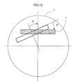
- FIG. 12 illustrates the manner of correcting the orientation of the machining attachment 8 by rotating the rotary C axis in an opposite direction by the displacement angle ⁇ of the reference plane 8a.
- Correction means for automatically correcting a mounting error of the workpiece 6 or the machining attachment 8 rotates the corresponding rotary axis in a direction opposite to that in which the workpiece 6 or the machining attachment 8 is displaced, by an angle equal to the obtained displacement angle, thereby automatically correcting the mounting error of the workpiece 6 or the machining attachment 8.
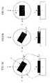
- FIGS. 13a-13c illustrate the manner of automatically correcting a mounting error of the workpiece 6.
- An inclination of the workpiece 6 is obtained according to the theory explained above with reference to FIG. 10 .
- the workpiece 6 is placed on the rotary B-axis table 4 as shown in FIG. 13a , and the probe 11 is allowed to contact with a side surface of the workpiece 6.
- the probe 11 is relatively shifted in the Z-axis direction and is again allowed to contact with the side surface of the workpiece 6 to detect the contact position. Based on the detection results obtained using the probe as shown in FIGS.
- the displacement angle of the workpiece 6 is derived, and the rotary table is rotated by an angle corresponding to the displacement angle such that the workpiece is positioned with its side surfaces directed parallel with the X and Z axes, as shown in FIG. 13c , thereby correcting the mounting error of the workpiece.
- Two points on an identical surface of the workpiece 6 are selected as the contact positions.
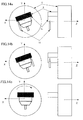
- FIGS. 14a-14c illustrate the manner of automatically correcting a mounting error of the machining attachment 8.
- An inclination of the machining attachment 8 is obtained according to the theory explained above with reference to FIG. 10 .
- the probe 11 is allowed to contact with the reference plane 8a of the machining attachment 8, as shown in FIG. 14a , to detect the contact position.
- the probe 11 is relatively shifted in the X-axis direction and is again allowed to contact with the reference plane 8a of the machining attachment 8 to detect the contact position.
- the rotary C-axis table 5 is rotated by an angle corresponding to the displacement angle of the reference plane 8a, as shown in FIG. 14c , to correct the mounting error of the reference plane 8a of the machining attachment 8.
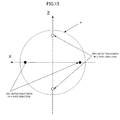
- FIG. 15 exemplifies contact detection points where the probe 11 is allowed to contact with a workpiece in cases where the mounting position of the machining attachment 8 relative to a machining surface of the workpiece 6 is to be corrected.
- two points aligned in the X- or Z-axis direction are set, as the contact detection points, on the upper surface of the workpiece 6 placed on the rotary B-axis table 4.
- FIGS. 16a and 16b illustrate the manner of how the probe is allowed to contact with the machining surface of the workpiece 6 in the case where the tool is fed in the X-axis direction, as shown in FIG. 15 .
- the probe 11 is allowed to contact with a point on the machining surface shown in FIG. 16a , and then again allowed to contact with another point on the machining surface shown in FIG. 16b , to detect respective contact positions.
- FIGS. 17a and 17b illustrate the manner of how the probe is allowed to contact with the machining surface of the workpiece 6 in the case where the tool is fed in the Z-axis direction, as shown in FIG. 15 .
- the probe 11 is allowed to contact with a point on the machining surface shown in FIG. 17a , and then again allowed to contact with another point on the machining surface shown in FIG. 17b , to detect respective contact positions.
- FIG. 18 illustrates the manner of how machining coordinate values are corrected during scribing at a fixed feed pitch in cases where the arrangement of the axes does not permit the orientation to be corrected by means of a rotary axis.
Landscapes
- Engineering & Computer Science (AREA)
- Human Computer Interaction (AREA)
- Manufacturing & Machinery (AREA)
- Physics & Mathematics (AREA)
- General Physics & Mathematics (AREA)
- Automation & Control Theory (AREA)
- Automatic Control Of Machine Tools (AREA)
- Machine Tool Sensing Apparatuses (AREA)
- Numerical Control (AREA)
Applications Claiming Priority (1)
| Application Number | Priority Date | Filing Date | Title |
|---|---|---|---|
| JP2007198791A JP4291382B2 (ja) | 2007-07-31 | 2007-07-31 | 接触検知による取り付け誤差の自動補正機能を有する工作機械 |
Publications (1)
| Publication Number | Publication Date |
|---|---|
| EP2026152A2 true EP2026152A2 (fr) | 2009-02-18 |
Family
ID=39884317
Family Applications (1)
| Application Number | Title | Priority Date | Filing Date |
|---|---|---|---|
| EP08104796A Withdrawn EP2026152A2 (fr) | 2007-07-31 | 2008-07-18 | Machine-outil disposant d'une fonction de correction d'erreurs d'assemblages par une détection de contact |
Country Status (4)
| Country | Link |
|---|---|
| US (1) | US7852031B2 (fr) |
| EP (1) | EP2026152A2 (fr) |
| JP (1) | JP4291382B2 (fr) |
| CN (1) | CN101357443A (fr) |
Cited By (3)
| Publication number | Priority date | Publication date | Assignee | Title |
|---|---|---|---|---|
| CN101987424B (zh) * | 2009-07-30 | 2012-09-26 | 中国商用飞机有限责任公司 | 数控机床主轴体的摆角校正方法 |
| CN103781590A (zh) * | 2011-12-14 | 2014-05-07 | 松下电器产业株式会社 | 超精密复合加工装置中的加工机构的判断方法及超精密复合加工装置 |
| EP4216007A1 (fr) * | 2022-01-21 | 2023-07-26 | Pratt & Whitney Canada Corp. | Procédé d'usinage d'une caractéristique dans un composant de moteur d'aéronef |
Families Citing this family (60)
| Publication number | Priority date | Publication date | Assignee | Title |
|---|---|---|---|---|
| JP4276252B2 (ja) * | 2006-10-31 | 2009-06-10 | ファナック株式会社 | 工具とワークの接触検知機構を有する工作機械 |
| SE530573C2 (sv) * | 2006-11-16 | 2008-07-08 | Hexagon Metrology Ab | Förfarande och anordning för kompensering av geometriska fel i bearbetningsmaskiner |
| JP5312032B2 (ja) * | 2007-06-29 | 2013-10-09 | 株式会社東京精密 | 表面形状測定装置及び表面形状測定方法 |
| JP4653824B2 (ja) * | 2008-07-29 | 2011-03-16 | ファナック株式会社 | 機上計測装置にて計測対象物の形状を計測する工作機械システム |
| JP2010105063A (ja) * | 2008-10-28 | 2010-05-13 | Fanuc Ltd | 温度ドリフト補正を行う機上計測装置を用いるワークの形状計測方法および機上計測装置を備えた工作機械 |
| JP4676549B2 (ja) * | 2009-09-10 | 2011-04-27 | ファナック株式会社 | 軌跡表示装置及び該軌跡表示装置を備えた工作機械 |
| JP2011235412A (ja) * | 2010-05-12 | 2011-11-24 | Honda Motor Co Ltd | クランプ装置 |
| JP5088975B2 (ja) * | 2010-10-19 | 2012-12-05 | 株式会社ソディック | ワイヤ放電加工装置 |
| DE112011104760T5 (de) * | 2011-01-24 | 2013-12-19 | Mitsubishi Electric Corporation | Fehlermessvorrichtung und Fehlermessverfahren |
| JP4938137B1 (ja) * | 2011-03-03 | 2012-05-23 | ファナック株式会社 | 被加工物の上面検出機能を有するワイヤカット放電加工機 |
| US8761920B2 (en) * | 2011-03-16 | 2014-06-24 | GM Global Technology Operations LLC | Automatic probing, compensation, and adjustment of a flexible fixture for a CNC machine |
| JP5226839B2 (ja) * | 2011-08-17 | 2013-07-03 | ファナック株式会社 | 位置決め精度補正機能を備えたワイヤ放電加工機 |
| JP5221744B2 (ja) * | 2011-11-28 | 2013-06-26 | ファナック株式会社 | 回転軸に取り付けた超高硬度材を用いた工具を加工するワイヤ放電加工方法およびワイヤ放電加工機 |
| JP5173016B1 (ja) * | 2011-12-22 | 2013-03-27 | ファナック株式会社 | 機上計測装置を有する工作機械 |
| EP2807447B1 (fr) * | 2012-01-26 | 2017-11-08 | Carl Zeiss Industrielle Messtechnik GmbH | Procédé de détermination d'une valeur de correction pour un contrôle d'un palier à fluide, et machine présentant au moins un palier à fluide |
| CN103419081A (zh) * | 2012-05-16 | 2013-12-04 | 辅佳材料科技股份有限公司 | 床台同步定位补偿系统 |
| CN102935604A (zh) * | 2012-11-02 | 2013-02-20 | 慈溪市汇丽机电有限公司 | 一种加工工件角度校正方法 |
| CN105026884B (zh) * | 2013-01-09 | 2019-10-18 | 卡尔蔡司工业测量技术有限公司 | 用于求取旋转位置求取系统的误差的方法 |
| DE102013018654A1 (de) * | 2013-10-30 | 2015-04-30 | Jenoptik Automatisierungstechnik Gmbh | Verfahren und Vorrichtung zur Detektion und zur Korrektur einer räumlichen Lage eines in einer Positionierungseinrichtung gehaltenen Werkstücks |
| CN105094045B (zh) * | 2014-05-09 | 2017-11-10 | 上海铼钠克数控科技股份有限公司 | 数控机床及利用其实施的定位加工方法 |
| JP6203780B2 (ja) * | 2015-04-21 | 2017-09-27 | ファナック株式会社 | テーブル形式データによる運転を行う数値制御装置 |
| CN107615197B (zh) * | 2015-05-12 | 2020-07-14 | 三菱电机株式会社 | 数控装置 |
| US9815198B2 (en) * | 2015-07-23 | 2017-11-14 | X Development Llc | System and method for determining a work offset |
| US10016892B2 (en) | 2015-07-23 | 2018-07-10 | X Development Llc | System and method for determining tool offsets |
| JP6758098B2 (ja) * | 2015-08-06 | 2020-09-23 | Thk株式会社 | 位置制御装置及び方法 |
| CN105397549B (zh) * | 2015-12-30 | 2017-10-03 | 广西玉柴机器股份有限公司 | 机床加工孔面工件的找零点方法 |
| CN105880904B (zh) * | 2016-04-11 | 2017-09-19 | 浙江陆虎汽车有限公司 | 顶盖横梁防错导向检测机构 |
| CN110249720B (zh) * | 2017-02-14 | 2020-08-18 | 雅马哈发动机株式会社 | 被安装物作业装置 |
| CN106903801B (zh) * | 2017-03-28 | 2019-10-25 | 百能数控设备(福建)有限公司 | 一种石材表面加工设备 |
| IT201700046674A1 (it) * | 2017-04-28 | 2018-10-28 | Matrix Srl | Macchina affilatrice |
| CN109708607A (zh) * | 2017-10-26 | 2019-05-03 | 富鼎电子科技(嘉善)有限公司 | 检测装置、检测方法及存储设备 |
| CN108098455B (zh) * | 2017-11-14 | 2019-08-02 | 武汉船用机械有限责任公司 | 一种工件找正方法 |
| CN109991923B (zh) * | 2017-12-29 | 2021-10-01 | 富泰华工业(深圳)有限公司 | 多角度加工坐标计算及补偿装置、方法和存储设备 |
| JP6804479B2 (ja) * | 2018-01-15 | 2020-12-23 | Dmg森精機株式会社 | モータ駆動制御装置およびこれを備えてなる工作機械 |
| US11874101B2 (en) | 2018-04-12 | 2024-01-16 | Faro Technologies, Inc | Modular servo cartridges for precision metrology |
| US10969760B2 (en) | 2018-04-12 | 2021-04-06 | Faro Technologies, Inc. | Coordinate measurement system with auxiliary axis |
| EP3667443B1 (fr) * | 2018-12-14 | 2025-06-04 | Agie Charmilles SA | Procédé de correction de mouvements d'axe |
| CN111381557B (zh) * | 2018-12-29 | 2023-09-19 | 鸿富锦精密电子(成都)有限公司 | 基于单机的加工设备误差补正方法及系统 |
| CN111381558B (zh) | 2018-12-29 | 2023-08-15 | 鸿富锦精密电子(成都)有限公司 | 加工设备误差补正方法及系统 |
| CN111381563B (zh) | 2018-12-29 | 2023-08-15 | 鸿富锦精密电子(成都)有限公司 | 加工设备误差补正方法及系统 |
| CN111381556A (zh) * | 2018-12-29 | 2020-07-07 | 鸿富锦精密电子(成都)有限公司 | 加工设备误差补正方法及系统 |
| CN109781165B (zh) * | 2018-12-29 | 2021-02-09 | 南京协辰电子科技有限公司 | 探头定位偏差的检测及其辅助方法、装置及系统 |
| CN109521728A (zh) * | 2019-01-10 | 2019-03-26 | 江苏匠准数控机床有限公司 | 一种数控机床自动寻点加工工艺 |
| JPWO2020174585A1 (ja) | 2019-02-26 | 2021-03-11 | 国立大学法人東海国立大学機構 | 切削装置および接触位置特定プログラム |
| JP6978457B2 (ja) * | 2019-02-28 | 2021-12-08 | ファナック株式会社 | 情報処理装置および情報処理方法 |
| CN109822364A (zh) * | 2019-03-02 | 2019-05-31 | 杭州职业技术学院 | 一种数控机床加工用夹头 |
| JP6788207B2 (ja) * | 2019-04-16 | 2020-11-25 | 株式会社東京精密 | 変位検出器、表面性状測定機、及び真円度測定機 |
| JP7473306B2 (ja) * | 2019-08-14 | 2024-04-23 | ファナック株式会社 | 機上測定装置、工作機械、および、機上測定方法 |
| CN110919458B (zh) * | 2019-11-20 | 2021-02-05 | 深圳市翔通光电技术有限公司 | 数控机床旋转轴的自动校准系统及方法 |
| JP7120512B2 (ja) | 2019-11-22 | 2022-08-17 | Smc株式会社 | 軌跡制御装置 |
| CN113534857A (zh) * | 2020-04-20 | 2021-10-22 | 杭州三花研究院有限公司 | 一种位置调节器及一种控制方法 |
| CN111745463B (zh) * | 2020-06-29 | 2021-08-24 | 北京航空航天大学 | 一种基于在机测量前置文件的误差补偿规划方法及系统 |
| CN112631199B (zh) * | 2020-11-27 | 2021-10-01 | 上海柏楚电子科技股份有限公司 | 用于标定机床的结构性参数的方法、装置及机床控制系统 |
| CN113084669A (zh) * | 2021-03-08 | 2021-07-09 | 东莞长盈精密技术有限公司 | 打磨治具、打磨设备、及打磨方法 |
| CN114161224A (zh) * | 2021-11-18 | 2022-03-11 | 富曜半导体(昆山)有限公司 | 一种机外预调校正装置 |
| CN115046513B (zh) * | 2022-07-07 | 2023-06-20 | 广东钶锐锶数控技术股份有限公司东莞分公司 | 一种机床精度检测工具及方法 |
| CN115351568A (zh) * | 2022-08-30 | 2022-11-18 | 安徽朗轶工业自动化系统有限公司 | 一种电机机座的钻攻铣削加工工艺及定位装置 |
| CN115302288B (zh) * | 2022-10-11 | 2022-12-20 | 四川工程职业技术学院 | 一种基于三点定位铣削精度修正的装置及方法 |
| CN117124136B (zh) * | 2023-10-20 | 2024-01-26 | 崴立机电(苏州)有限公司 | 一种机床的校正方法、系统、装置和介质 |
| CN119270762B (zh) * | 2024-09-30 | 2025-05-23 | 东莞市深亚精密机械有限公司 | 工件位置调整方法、装置、电子设备及可读存储介质 |
Citations (1)
| Publication number | Priority date | Publication date | Assignee | Title |
|---|---|---|---|---|
| JPH0626787B2 (ja) | 1987-06-15 | 1994-04-13 | 日本鉱業株式会社 | 切断装置における傾き検出方法 |
Family Cites Families (17)
| Publication number | Priority date | Publication date | Assignee | Title |
|---|---|---|---|---|
| JPH0688340B2 (ja) * | 1988-03-28 | 1994-11-09 | 新日本工機株式会社 | テープの自動貼付装置 |
| JP2708458B2 (ja) * | 1988-04-01 | 1998-02-04 | 株式会社豊田中央研究所 | 倣い制御ロボット |
| JP2810709B2 (ja) * | 1989-07-27 | 1998-10-15 | ファナック 株式会社 | 非接触ならい制御装置 |
| JPH0482658A (ja) * | 1990-07-25 | 1992-03-16 | Fanuc Ltd | 非接触ならい制御装置 |
| JPH04115854A (ja) * | 1990-09-07 | 1992-04-16 | Fanuc Ltd | 非接触ならい制御装置 |
| JPH0531653A (ja) * | 1991-07-26 | 1993-02-09 | Fanuc Ltd | 非接触倣い制御方式 |
| US5550330A (en) * | 1991-10-16 | 1996-08-27 | Fanuc Limited | Digitizing control apparatus |
| CA2082790A1 (fr) | 1991-12-02 | 1993-06-03 | R. David Hemmerle | Systeme de maintenance automatise pour machines a commande numerique par ordinateur |
| US5495090A (en) * | 1992-06-29 | 1996-02-27 | Matsushita Electric Industrial Co., Ltd. | Welding robot |
| JPH06106457A (ja) | 1992-09-28 | 1994-04-19 | Amada Co Ltd | 加工機における可動部位置検出方法及び検出装置 |
| US6233497B1 (en) * | 1997-09-18 | 2001-05-15 | Mitsubishi Denki Kabushiki Kaisha | Contact detecting method and an apparatus for the same |
| JP2004192152A (ja) | 2002-12-09 | 2004-07-08 | Fuji Heavy Ind Ltd | 数値制御装置 |
| JP4782990B2 (ja) * | 2004-05-31 | 2011-09-28 | 株式会社ミツトヨ | 表面倣い測定装置、表面倣い測定方法、表面倣い測定プログラムおよび記録媒体 |
| CN1775442A (zh) | 2004-11-15 | 2006-05-24 | 发那科株式会社 | 电火花线切割机和电火花线切割加工方法 |
| JP2006159396A (ja) * | 2004-11-15 | 2006-06-22 | Fanuc Ltd | ワイヤ放電加工機及びワイヤ放電加工方法 |
| JP2006212765A (ja) | 2005-02-07 | 2006-08-17 | Enshu Ltd | 工作機械の熱変位補正方法 |
| JP2006289524A (ja) | 2005-04-06 | 2006-10-26 | Fanuc Ltd | 加工物設置誤差測定装置 |
-
2007
- 2007-07-31 JP JP2007198791A patent/JP4291382B2/ja not_active Expired - Fee Related
-
2008
- 2008-07-18 US US12/175,823 patent/US7852031B2/en active Active
- 2008-07-18 EP EP08104796A patent/EP2026152A2/fr not_active Withdrawn
- 2008-07-30 CN CNA2008101447182A patent/CN101357443A/zh active Pending
Patent Citations (1)
| Publication number | Priority date | Publication date | Assignee | Title |
|---|---|---|---|---|
| JPH0626787B2 (ja) | 1987-06-15 | 1994-04-13 | 日本鉱業株式会社 | 切断装置における傾き検出方法 |
Cited By (5)
| Publication number | Priority date | Publication date | Assignee | Title |
|---|---|---|---|---|
| CN101987424B (zh) * | 2009-07-30 | 2012-09-26 | 中国商用飞机有限责任公司 | 数控机床主轴体的摆角校正方法 |
| CN103781590A (zh) * | 2011-12-14 | 2014-05-07 | 松下电器产业株式会社 | 超精密复合加工装置中的加工机构的判断方法及超精密复合加工装置 |
| US9612594B2 (en) | 2011-12-14 | 2017-04-04 | Panasonic Intellectual Property Management Co., Ltd. | Method for determining a machining means in hybrid ultraprecision machining device, and hybrid ultraprecision machining device |
| EP4216007A1 (fr) * | 2022-01-21 | 2023-07-26 | Pratt & Whitney Canada Corp. | Procédé d'usinage d'une caractéristique dans un composant de moteur d'aéronef |
| US12276962B2 (en) | 2022-01-21 | 2025-04-15 | Pratt & Whitney Canada Corp. | Method of machining a feature in an aircraft engine component |
Also Published As
| Publication number | Publication date |
|---|---|
| US20090033271A1 (en) | 2009-02-05 |
| CN101357443A (zh) | 2009-02-04 |
| JP2009034738A (ja) | 2009-02-19 |
| US7852031B2 (en) | 2010-12-14 |
| JP4291382B2 (ja) | 2009-07-08 |
Similar Documents
| Publication | Publication Date | Title |
|---|---|---|
| US7852031B2 (en) | Machine tool having function of correcting mounting error through contact detection | |
| KR101130596B1 (ko) | 기상 계측 장치의 프로브 장착 위치 산출 방법 | |
| US7571669B2 (en) | Machining apparatus for noncircular shapes | |
| EP2221689B1 (fr) | Machine-outil et son procédé de commande | |
| CN112008496B (zh) | 机床对象物的位置计测方法及位置计测系统 | |
| JP4684428B2 (ja) | ツールプリセッタ | |
| US9964939B2 (en) | Trajectory display device for displaying trajectory of tool axis | |
| US20060136088A1 (en) | Numerical control apparatus and numerical control system | |
| CN107303644B (zh) | 机床上的对象物的位置计测方法及位置计测系统 | |
| EP2214070B1 (fr) | Machine-outil avec mesure de la taille de la pièce | |
| US20080063483A1 (en) | Method for setting working origin and machine tool for implementing the same | |
| CN112775720B (zh) | 机床的对象物的位置测量方法及位置测量系统、计算机可读记录介质 | |
| JP2020159752A (ja) | 主軸振動測定システム、主軸振動測定方法、およびプログラム | |
| JP2008241608A (ja) | ワーク基準点機上検出方法及びその方法を用いた加工装置 | |
| JP2002273642A (ja) | ボールネジ送り駆動補正方法及びボールネジ送り駆動装置 | |
| JPH091443A (ja) | 測定装置 | |
| JP2014237204A (ja) | 工作機械 | |
| CN111624940B (zh) | 信息处理装置以及信息处理方法 | |
| US20070145932A1 (en) | Controller for machine tool | |
| JP2919754B2 (ja) | 球面又は円弧面加工時におけるバックラッシュ計測補正装置 | |
| JP3405744B2 (ja) | 工作機械におけるワーク及び経時変化の計測方法 | |
| EP4134762A1 (fr) | Procédé d'usinage | |
| JPH05185304A (ja) | 自動旋盤 | |
| JPH06246589A (ja) | 機内測定による非円形ワークの誤差補正方法 | |
| JP2017117282A (ja) | 工作機械及び工作機械の制御方法 |
Legal Events
| Date | Code | Title | Description |
|---|---|---|---|
| PUAI | Public reference made under article 153(3) epc to a published international application that has entered the european phase |
Free format text: ORIGINAL CODE: 0009012 |
|
| AK | Designated contracting states |
Kind code of ref document: A2 Designated state(s): AT BE BG CH CY CZ DE DK EE ES FI FR GB GR HR HU IE IS IT LI LT LU LV MC MT NL NO PL PT RO SE SI SK TR |
|
| AX | Request for extension of the european patent |
Extension state: AL BA MK RS |
|
| STAA | Information on the status of an ep patent application or granted ep patent |
Free format text: STATUS: THE APPLICATION HAS BEEN WITHDRAWN |
|
| 18W | Application withdrawn |
Effective date: 20100125 |