EP2046668B1 - Dispositif de transport pour dépalétiser des marchandises empilées sur un support de marchandises - Google Patents
Dispositif de transport pour dépalétiser des marchandises empilées sur un support de marchandises Download PDFInfo
- Publication number
- EP2046668B1 EP2046668B1 EP07784603A EP07784603A EP2046668B1 EP 2046668 B1 EP2046668 B1 EP 2046668B1 EP 07784603 A EP07784603 A EP 07784603A EP 07784603 A EP07784603 A EP 07784603A EP 2046668 B1 EP2046668 B1 EP 2046668B1
- Authority
- EP
- European Patent Office
- Prior art keywords
- conveyor
- arrangement
- goods
- conveyor system
- accommodating
- Prior art date
- Legal status (The legal status is an assumption and is not a legal conclusion. Google has not performed a legal analysis and makes no representation as to the accuracy of the status listed.)
- Not-in-force
Links
- 238000012546 transfer Methods 0.000 claims abstract description 18
- 230000008878 coupling Effects 0.000 claims description 5
- 238000010168 coupling process Methods 0.000 claims description 5
- 238000005859 coupling reaction Methods 0.000 claims description 5
- 238000011144 upstream manufacturing Methods 0.000 claims description 2
- 238000006073 displacement reaction Methods 0.000 claims 9
- 230000001747 exhibiting effect Effects 0.000 claims 1
- 238000005096 rolling process Methods 0.000 claims 1
- 238000000034 method Methods 0.000 abstract description 3
- 238000013461 design Methods 0.000 description 5
- 230000007246 mechanism Effects 0.000 description 4
- 238000012549 training Methods 0.000 description 4
- 238000011161 development Methods 0.000 description 3
- 230000018109 developmental process Effects 0.000 description 3
- 238000012423 maintenance Methods 0.000 description 3
- 230000008901 benefit Effects 0.000 description 2
- 230000015572 biosynthetic process Effects 0.000 description 2
- 230000008859 change Effects 0.000 description 2
- 230000035515 penetration Effects 0.000 description 2
- 230000008569 process Effects 0.000 description 2
- 230000002441 reversible effect Effects 0.000 description 2
- 230000007306 turnover Effects 0.000 description 2
- 208000036829 Device dislocation Diseases 0.000 description 1
- 230000001133 acceleration Effects 0.000 description 1
- 230000004308 accommodation Effects 0.000 description 1
- 238000000429 assembly Methods 0.000 description 1
- 230000000712 assembly Effects 0.000 description 1
- 239000011324 bead Substances 0.000 description 1
- 239000000969 carrier Substances 0.000 description 1
- 239000007822 coupling agent Substances 0.000 description 1
- 238000000151 deposition Methods 0.000 description 1
- 238000001514 detection method Methods 0.000 description 1
- 239000003292 glue Substances 0.000 description 1
- 230000014759 maintenance of location Effects 0.000 description 1
- 238000005259 measurement Methods 0.000 description 1
- 238000012856 packing Methods 0.000 description 1
- 230000000750 progressive effect Effects 0.000 description 1
- 230000009467 reduction Effects 0.000 description 1
- 238000000926 separation method Methods 0.000 description 1
Images



Classifications
-
- B—PERFORMING OPERATIONS; TRANSPORTING
- B65—CONVEYING; PACKING; STORING; HANDLING THIN OR FILAMENTARY MATERIAL
- B65G—TRANSPORT OR STORAGE DEVICES, e.g. CONVEYORS FOR LOADING OR TIPPING, SHOP CONVEYOR SYSTEMS OR PNEUMATIC TUBE CONVEYORS
- B65G59/00—De-stacking of articles
- B65G59/02—De-stacking from the top of the stack
- B65G59/026—De-stacking from the top of the stack with a stepwise upward movement of the stack
-
- B—PERFORMING OPERATIONS; TRANSPORTING
- B65—CONVEYING; PACKING; STORING; HANDLING THIN OR FILAMENTARY MATERIAL
- B65G—TRANSPORT OR STORAGE DEVICES, e.g. CONVEYORS FOR LOADING OR TIPPING, SHOP CONVEYOR SYSTEMS OR PNEUMATIC TUBE CONVEYORS
- B65G1/00—Storing articles, individually or in orderly arrangement, in warehouses or magazines
- B65G1/02—Storage devices
- B65G1/04—Storage devices mechanical
- B65G1/0407—Storage devices mechanical using stacker cranes
-
- B—PERFORMING OPERATIONS; TRANSPORTING
- B65—CONVEYING; PACKING; STORING; HANDLING THIN OR FILAMENTARY MATERIAL
- B65G—TRANSPORT OR STORAGE DEVICES, e.g. CONVEYORS FOR LOADING OR TIPPING, SHOP CONVEYOR SYSTEMS OR PNEUMATIC TUBE CONVEYORS
- B65G1/00—Storing articles, individually or in orderly arrangement, in warehouses or magazines
- B65G1/02—Storage devices
- B65G1/04—Storage devices mechanical
- B65G1/137—Storage devices mechanical with arrangements or automatic control means for selecting which articles are to be removed
- B65G1/1373—Storage devices mechanical with arrangements or automatic control means for selecting which articles are to be removed for fulfilling orders in warehouses
- B65G1/1378—Storage devices mechanical with arrangements or automatic control means for selecting which articles are to be removed for fulfilling orders in warehouses the orders being assembled on fixed commissioning areas remote from the storage areas
-
- B—PERFORMING OPERATIONS; TRANSPORTING
- B65—CONVEYING; PACKING; STORING; HANDLING THIN OR FILAMENTARY MATERIAL
- B65G—TRANSPORT OR STORAGE DEVICES, e.g. CONVEYORS FOR LOADING OR TIPPING, SHOP CONVEYOR SYSTEMS OR PNEUMATIC TUBE CONVEYORS
- B65G59/00—De-stacking of articles
- B65G59/005—De-stacking of articles by using insertions or spacers between the stacked layers
-
- B—PERFORMING OPERATIONS; TRANSPORTING
- B65—CONVEYING; PACKING; STORING; HANDLING THIN OR FILAMENTARY MATERIAL
- B65G—TRANSPORT OR STORAGE DEVICES, e.g. CONVEYORS FOR LOADING OR TIPPING, SHOP CONVEYOR SYSTEMS OR PNEUMATIC TUBE CONVEYORS
- B65G59/00—De-stacking of articles
- B65G59/02—De-stacking from the top of the stack
- B65G59/023—De-stacking from the top of the stack by means insertable between the stacked articles or layers
Definitions
- the invention relates to a conveyor as described in claim 1.
- a conveyor for depalletizing and conveying of goods stacked on a goods carrier in multiple layers corresponds to the preamble of claim 1 and has a Huburevoriques with a load supporting means for the goods carrier and, in a lifting direction perpendicularly extending conveying plane, in a Ableterrorism the goods relative to the load supporting means adjustable, the load supporting means facing a conveyor plane inclined casserole plane having conveyor on.
- This is formed by a receiving conveyor device which can be moved reversibly in the conveying direction by means of an adjusting drive in a guide path and at least one transfer conveyor device which is arranged downstream in the discharge direction and forms the casserole plane.
- a conveyor for the layer-wise Depalettieren of stacked goods on a goods carrier in which a goods carrier is superimposed on the goods on a lifting conveyor formed by a scissor lift and with the goods stack according to the depalletizing position with respect to one in the Ab lakecardi the situation downstream, a conveying plane forming discharge device is positioned in the vertical plane to the conveying plane.
- a device for depalletizing layers on a goods carrier stacked article in which lifted by a lifting device with a suction device to be depalletized layer from the goods carrier and delivered on a conveyor downstream conveying direction and by means of another independent lifting device between the layers arranged separating layers, eg separating cartons, lifted after removing the position of the article and stacked in a arranged next to the parking space of the goods carrier storage device.
- the object of the invention is to provide a conveyor for depalletizing and removal or further conveying on a goods carrier, in particular a pallet, stacked in several layers goods or containers are minimized with the manipulation idle times to speed up the Depaletti mecanicsvorganges.
- an increased wear causing recording resistances when retracting the receiving conveyor or the conveyor modules between the layers are largely reduced and wear, due to a relative movement of the conveyor and the male goods or goods containers, suspended components, such as subsidies, eg Conveyor belts, conveyor belts, technically and inexpensively easier exchangeable as well as a casserole level by a positional tuning of the conveyor modules or a superior conveyor roller can be optimized.
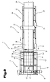
- a conveyor 1 for depalletizing and Abf or Weitefördem on a goods carrier 2, for example, a pallet, in several layers 3 stacked goods 4 or 5 goods packages, eg packs, bottles, containers, etc. shown.
- goods carrier 2 for example, a pallet
- the layers 3 are stacked directly on top of each other or else stacked using a separating layer 6 between the layers 3, for example a separating carton.
- the conveyor 1 consists essentially of a Hubtownvoriques 7 with a supported on a footprint 8 and extending to this in a vertical direction mast assembly, preferably with two parallel masts 9 form the guide assemblies 10 in which via a lifting drive 11, e.g. by means of an electrically operated traction drive 12, a load supporting means 13 adjustable - according to double arrow 14 - is stored.
- the illustrated embodiment shows a 2-tier arrangement in which in a lower floor by means of a pallet conveyor, eg roller conveyor, the goods carrier 2 with the goods stacked thereon 4 or goods packages 5 are supplied and arranged on the load supporting means 13 roller or traction mechanism 15 are taken on the load carrying means 13.
- a pallet conveyor eg roller conveyor
- de-depalletizing is carried out after positioning of the goods carrier 2 with the Hubanivoriques 7 for a removal in a Ab lakecardi - according to arrow 17 - the position 3 or only one of the goods package 5, for example one or more Rows of the stacked goods 4 in the vertical direction with respect to a discharge device 18.
- the takeover of the goods 4 or container 5 by the discharge device 18 takes place, as known per se, by driving under the depalletizing layer 3 with the discharge device 18 in a parting plane - as described in more detail later.
- the layer 3 or bundle of containers is picked up by the receiving conveyor device 18 and conveyed away in the discharge direction - according to arrow 17 - transfer conveyor 19, the conveyors 20, preferably conveyor belts form a common conveying plane 21, parallel to the footprint 8.
- the receiving conveyor 18 and the transfer conveyor 19 are in a parallel to the conveying plane 21 extending guideway 22 and each have their own adjustment 23, 24 independently in the Ab lakecardi- according to arrow 17 - reversible - according to arrows 25, 26 - movable, the adjustability designed is that the receiving conveyor device 18 and the transfer conveyor 19 with the conveying means 20 are close to tight or in a maximum distance 27 adjustable, which corresponds approximately to a length 28 of the load supporting means 13.
- Hubacivoriques 7 remote end position of the transfer conveyor 19 is provided in the discharge - according to arrow 17 - a direct delivery and further promotion of depalletised goods 4 on a downstream discharge device 29, where appropriate, a separating device, distribution device, etc. may be arranged in front.
- the receiving conveyor 18 is preferably, for a safe transport, differently shaped goods package 5, formed by a belt conveyor 30, which in one of the Hubanimpf 7 facing end portion 31 at least one, preferably on a support frame 32, preferably via coupling means 33, fixed conveyor module 34 which is wedge-shaped in the direction of Hubanivoriques 7 and thus forms a conveyor plane 21 inclined inclined casserole 35 forms.
- the receiving conveyor device 18, facing the load-bearing means 13 has a plurality of conveyor modules 34 adjacent to one another via the conveyor width, which are driven either by the receiving conveyor 18 or driven by a separate drive.
- the stringed conveyor modules 34 are drive coupled together, but are preferably for maintenance, e.g. Change of the belt, belt simply exchangeable to what the coupling means 33 are formed to allow this.
- a further advantageous embodiment is to provide the delivery modules 34 upstream of a driven conveyor roller 36, with a relatively small diameter and with a surface texture having a high coefficient of friction to provide.
- the feed roller 36 is driven by the drive of the receiving conveyor device 18 or by the conveyor modules 34 with.
- FIG. 1 and 2 how the next Fig. 1 and 2 can be seen, is on the mast 9 via a further lifting drive 37, for example, the traction drive 12, a support frame 38 in the stroke direction, relative to the load supporting means 13, adjustably mounted, on which a stop assembly 39 provided by a receiving space 40 three-sided bounding stop means 41.
- a stop means limits the receiving space 40 in the direction of the mast 9 and the other limit the receiving space 40 opposite each other laterally.
- the stop means 41 via adjusting means 42, for example, be acted upon with a pressure medium cylinder, between an inner position in which the stop means 41, the products arranged on the goods carrier 4 4 tight and an external position on the support frame 38 adjustably - according to double arrow 43 - arranged ,
- the stop means 41 By independent of the load supporting means 13 adjustability of the support frame 38 with the stop assembly 39, it is possible to position the stop means 41 relative to the load supporting means 13 in a position in which the depalletizing layer 3, so the layer 3 above the conveying plane 21, positioned secured becomes. Of course, it is also possible to choose a position of the stop means 41 below the conveying plane 21 if necessary. Further, the load carrying means 13 facing an adjustable, shield-like retaining means 44 extending over a conveyor width in the area below the discharge device 18 fixed, for example, arranged on the floor slab 16 to a hedge of the goods carrier 2 to remaining goods 4 or 5 goods in addition to to reach.
- stop assembly 39 a guidance of the goods to be depalleted 4 is achieved in a loose delivery of the stop means 41. Furthermore, it is also possible to achieve with the stop means 41 a tensioning of the layer 3 or a single row of the layer 3, in particular by means of individually adjustable clamping means on the stop means 41.
- Such a design allows, for example, with a vertical adjustment of the support frame 38 by means of the lifting drive 36 to lift on the receiving conveyor 18 to be transferred layer 3, thereby creating a free space for the receiving conveyor 18 and the conveyor modules 34 so as to take over the layer 18 to ensure the receiving conveyor 18.
- lifting may be advantageous for the Depalettiervorgang.
- a further linear guide arrangement 49 is provided, which is oriented vertically with respect to the conveying plane 21 and in which a cantilever arm 50 by means of a Hubtriebes 51, e.g. the traction mechanism, adjustable - according to double arrow 52 - is guided.
- a Hubtriebes 51 e.g. the traction mechanism, adjustable - according to double arrow 52 - is guided.
- a possible training is also in the boom arm 50 on the carriage 47 to to store a plane perpendicular to the conveying plane 21 pivot axis as will be described later in detail, whereby the load supporting means 13 laterally superior guide assembly 46 avoided for the carriage 47 and a technically simple adjustment of the boom 50 is achieved.
- a gripping device 54 with a pivot bearing 55 which forms parallel to the conveying plane 21 and in Ab currentlyides - according to arrow 17 - perpendicular pivot axis 56, a gripper head 57 pivotally mounted, for example is formed by a multi-armed lever 58 and the need-trained gripping means 59, eg Vacuum suction or lifting hook, pliers gripper, etc. can be fitted.
- the positioning of the gripping head 57, for each intended function, is carried out by pivoting the lever 58 between two end positions and this is done for example via a pressurizable with a pressure medium actuating means 60th
- the operation of the acceptance or lifting device 45 is shown for removing the released during depalletizing separation layer 6, which received in an operative position of the gripper head 57 and the lever 58 of a vacuum suction 61 and by lifting the gripper head 57 and adjustment in Ab lakecardi - According to arrow 17 - the separating layer 6 is replaced with progressive recording of the goods package 5 on the receiving conveyor 18 of the remaining layer 3 and recorded.
- the separating layer 6 is reliably detached even if, as it happens occasionally, it adheres to the lower layer 3, e.g. by glue residues, etc.
- Fig. 6 is shown in a simplified representation of the acceptance or lifting device 45 and on the basis of the figure, the other function, for example, lifting a bundle of containers 62, below a handling for goods package 5 described having at an upper edge 63 has a bead-shaped edge formation.
- At the gripper head 57 at least one lifting hook 64 is provided with the edge bead is under attack to accomplish an increase in the goods package 5.
- Such a container training often consists of stackable, an open filling opening having goods containers.
- adjustable receiving conveyor 18 of the gripper head 57 is moved to the boom 50 in the remote from the Hubanivoruze 7 end position and the gripper head 57 and the lever arm 58, which is provided on the one hand with the lifting hook 64 and on the other hand with the vacuum suction 61, adjusted by means of the actuating means 60 in an engaged position for the lifting hook 64.
- the goods package 5 or by the arrangement of several adjoining lifting hooks 64, the container train 62, which is provided for the depalletization, by raising the boom arm 50 - slightly upended as shown by arrow 66, whereby between the layers 3, a wedge-shaped space arises, which allows penetration of the wedge-shaped conveyor module 34 between the layers 3 during the adjustment of the receiving conveyor 18 and with which the lifting hook 64 is disengaged by adjusting the lever arm 58.
- the bundle of goods 5 or the bundle of containers 62 is received in sequence by the conveyor 20, the upper belt in the direction of adjustment - according to arrow 65 - opposite discharge device - according to arrow 17 - recorded.
- Fig. 6 can be seen that by the independent adjustment of the receiving conveyor 18 and the transfer conveyor 19 already during a Depallettiervorganges and takeover of the goods package 5 from the receiving conveyor 18, already located on the transfer conveyor 19 goods package 5, after an adjustment of the transfer conveyor 19 in the direction of the discharge device 29. according to arrow 67 - to promote.
- a high flexibility of the conveyor 1 according to the invention is achieved with a reduction of idle times thereby increasing the goods turnover and thus the cost-effectiveness of such devices.
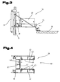
- a further embodiment of the stop assembly 39 is shown with the adjustable stop means 41.
- An adjustability of the receiving space 40 limiting stop means 41 allows a recording of the goods carrier, preferably an EU range, box, etc. in the transverse or longitudinal direction.
- the stop means 41 are supported on the support frame 38 via roll apparatuses 85 and adjustable between the inner position and the outer position by means of actuators 86.
- the support frame 38 is adjustably guided on the mast 9 by means of the lifting drive 37 and guide means 87 via pivoting arrangements 88 to a parallel to the footprint 8 and perpendicular to Abnchides - according to arrow 17 - extending pivot axis 89, from the position shown in solid lines in an in shown broken lines by means of drives 90, eg Pressure cylinders, spindle drives, rope drives, etc., adjustable.
- drives 90 eg Pressure cylinders, spindle drives, rope drives, etc.
- FIG. 8 is another embodiment of the acceptance and lifting device 45 with the boom 50 and on this via a carriage 91 and for example a cable drive 92 - according to double arrow 93 - movable gripping device 54 shown.
- the extension arm 50 is in a vertical guide rail 94 and reel unit 95 and, for example, another cable drive 96 - according to double arrow 97 - adjustable in the vertical direction to, for example, as shown, remove a release liner 6 of the stacked goods package 5.
- a storage position of the gripping device 54 is achieved at a pivoting about 90 ° from the position shown with which the separating layer 6 can be dispensed next to the Huburevorraum 7.
Landscapes
- Engineering & Computer Science (AREA)
- Mechanical Engineering (AREA)
- De-Stacking Of Articles (AREA)
- Warehouses Or Storage Devices (AREA)
Abstract
Claims (32)
- Équipement de transport (1) pour dépalettiser et pour évacuer et acheminer des marchandises (4) empilées en plusieurs couches sur un support de marchandises (2), comportant- un convoyeur de levage (7) avec un porte-charge (13) pour le support de marchandises (2);- dans un plan de transport (21) orienté perpendiculairement à une direction de levage, un dispositif de transport réglable par rapport au porte-charge (13) dans un système d'évacuation des marchandises (4), orienté vers le porte-charge (13) et comportant un plan de réception (35) incliné par rapport au plan de transport (21);ledit dispositif de transport étant formé par un convoyeur de réception (18), formant le plan de réception (35) et mobile de manière réversible dans le sens d'évacuation par un système d'entraînement (23) dans une voie de guidage (22), et par au moins un convoyeur de transfert (19), disposé en aval dans le sens d'évacuation et mobile dans la voie de guidage (22),
caractérisé en ce que l'équipement de transport (1) comporte un dispositif de prélèvement ou de levage (45) pour des intercalaires de séparation (6) des marchandises (4), agencés entre les couches, le dispositif de prélèvement ou de levage (45) comportant un dispositif préhenseur (54) orienté vers le plan de transport (21), et est disposé de préférence sur un mât (9) du convoyeur de levage (7) de manière mobile dans une direction perpendiculaire au plan de transport (21), et le dispositif préhenseur (54) est réalisé de manière mobile dans au moins une autre direction dans l'espace, et en ce que le convoyeur de transfert (19) est réalisé de manière mobile indépendamment dans la voie de guidage (22) par rapport au convoyeur de réception (18) par l'intermédiaire d'un deuxième système d'entraînement (24). - Équipement de transport (1) selon la revendication 1, caractérisé en ce que le dispositif de prélèvement ou de levage (45) peut être déplacé par un chariot mobile (47) muni d'un système d'entraînement (48), dans une direction perpendiculaire au plan de transport (21), le long d'un système de guidage (10) du mât (9).
- Équipement de transport (1) selon la revendication 2, caractérisé en ce que le dispositif préhenseur (54) est agencé mobile de manière réversible dans le sens d'évacuation, sur un bras en porte-à-faux (50) agencé sur le chariot mobile (47).
- Équipement de transport (1) selon la revendication 3, caractérisé en ce que le bras en porte-à-faux (50) avec le dispositif préhenseur (54) est monté de manière mobile dans un système de guidage (49) agencé sur le chariot mobile (47) et orienté transversalement au sens d'évacuation et parallèlement au plan de transport (21).
- Équipement de transport (1) selon la revendication 3 ou 4, caractérisé en ce que le bras en porte-à-faux (50) avec le dispositif préhenseur (54) est monté sur un appareil de roulement (95) dans un palier pivotant (98) et est apte à pivoter au moyen d'un système d'entraînement pivotant (100) autour d'un axe de pivotement (99) orienté perpendiculairement à une surface de charge (78) du porte-charge (13).
- Équipement de transport (1) selon la revendication 1, caractérisé en ce qu'un déplacement du dispositif préhenseur (54) dans le sens d'évacuation correspond sensiblement à une longueur (28) maximale du support de marchandises (2) ou à une profondeur maximale du porte-charge (13).
- Équipement de transport (1) selon la revendication 1, caractérisé en ce qu'un déplacement du dispositif préhenseur (54) dans une direction transversale au sens d'évacuation est supérieure à une largeur de transport du convoyeur de réception (18).
- Équipement de transport (1) selon la revendication 1, caractérisé en ce que le dispositif préhenseur (54) est formé par un crochet de levage (64).
- Équipement de transport (1) selon la revendication 1, caractérisé en ce que le dispositif préhenseur (54) est formé par une ventouse (61).
- Équipement de transport (1) selon la revendication 1, caractérisé en ce que le système d'entraînement (23) est relié en entraînement à un bâti de support du convoyeur de réception (18) par l'intermédiaire d'un élément de couplage élastique.
- Équipement de transport (1) selon la revendication 1, caractérisé en ce que le système d'entraînement (23) du convoyeur de réception (18) est réalisé pour un mouvement d'avance, ajustable aux forces appliquées, du convoyeur de réception (18).
- Équipement de transport (1) selon la revendication 1, caractérisé en ce que sur le porte-charge (13) ou sur le mât (9) du convoyeur de levage (7) est agencé, de manière mobile dans le sens de levage par rapport au porte-charge (13), un système de butée (39), qui entoure un espace de réception (40), délimité sur trois côtés et ouvert vers le convoyeur de réception (18), pour au moins une couche (3) de marchandises (4), et qui est formé par des moyens de butée (41) mobiles l'un par rapport à l'autre, de préférence indépendamment les uns des autres, entre une position intérieure et une position extérieure.
- Équipement de transport (1) selon la revendication 12, caractérisé en ce que le système de butée (39) est agencé sur un bâti de support (38) monté mobile sur le mât (9) par l'intermédiaire d'un système d'entraînement de levage (37), tel qu'un mécanisme de traction.
- Équipement de transport (1) selon la revendication 1, caractérisé en ce que dans une zone en dessous du plan de transport (21) est agencé un moyen de retenue (44) s'étendant sur la largeur de transport, indépendant du porte-charge (13), mobile de préférence vers l'espace de réception (40).
- Équipement de transport (1) selon la revendication 12, caractérisé en ce que les moyens de butée (41) du système de butée (39) comportent plusieurs moyens de serrage, agencés dans le sens du pourtour de l'espace de réception (40) et mobiles indépendamment les uns des autres entre la position intérieure et la position extérieure.
- Équipement de transport (1) selon la revendication 15, caractérisé en ce que les moyens de serrage agencés dans les moyens de butée (41) face à face sont mobiles, sensiblement de manière synchrone, entre la position intérieure et la position extérieure.
- Équipement de transport (1) selon la revendication 12, caractérisé en ce que le système de butée (39) est monté sur le mât (9) ou le porte-charge (13), de manière mobile par exemple dans une direction perpendiculaire à une surface de charge du porte-charge (13).
- Équipement de transport (1) selon l'une quelconque des revendications 12 à 17, caractérisé en ce que le système de butée (39) est apte à pivoter entre un plan orienté parallèlement ou en angle par rapport à ladite surface de charge.
- Équipement de transport (1) selon l'une quelconque des revendications 12 à 18, caractérisé en ce que le système de butée (39) avec les moyens de butée (41) est monté sur le bâti de support (38) de manière à pouvoir pivoter autour d'un axe de pivotement (89) parallèle au plan de transport (21).
- Équipement de transport (1) selon la revendication 14, caractérisé en ce que le moyen de retenue (44) est formé par un bouclier de butée s'étendant sur la largeur de transport.
- Équipement de transport (1) selon l'une quelconque des revendications 12 à 20, caractérisé en ce que des systèmes d'entraînement des moyens de butée (41) et/ou des moyens de serrage et/ou du moyen de retenue (44) sont formés par des moyens de réglage (42), tels que des vérins pneumatiques, sollicités par un fluide sous pression.
- Équipement de transport (1) selon la revendication 1, caractérisé en ce que dans la zone d'extrémité du convoyeur de réception (18) est agencé de manière amovible, par l'intermédiaire de moyens de couplage (33) par exemple, au moins un module de transport (34) formant le plan de réception (35).
- Équipement de transport (1) selon la revendication 22, caractérisé en ce que les moyens de couplage (33) sont réalisés sous forme élastique sensiblement dans le sens d'évacuation des marchandises (4).
- Équipement de transport (1) selon la revendication 22, caractérisé en ce que le module de transport (34) est monté sur le convoyeur de réception (18) de manière à pouvoir pivoter autour d'un axe de pivotement parallèle au plan de transport (21) et sensiblement perpendiculaire au sens d'évacuation, pour régler l'inclinaison du plan de réception (35).
- Équipement de transport (1) selon l'une quelconque des revendications 22 à 24, caractérisé en ce que le module de transport (34) est monté, en particulier de manière flexible, sur le bâti de support du convoyeur de réception (18), de manière mobile sensiblement dans le sens d'évacuation des marchandises (4).
- Équipement de transport (1) selon l'une quelconque des revendications 22 à 25, caractérisé en ce qu'un ou plusieurs modules de transport (34) sont agencés sur la largeur de transport de manière permutable sur le bâti de support du convoyeur de réception (18).
- Équipement de transport (1) selon l'une quelconque des revendications 22 à 26, caractérisé en ce que module de transport (34) est formé par un convoyeur à bande ou courroie.
- Équipement de transport (1) selon l'une quelconque des revendications 22 à 27, caractérisé en ce qu'un cylindre de transport (36) actionné est monté en amont du module de transport (34).
- Équipement de transport (1) selon la revendication 28, caractérisé en ce que le cylindre de transport (36) est monté, de préférence de manière flexible, sur le bâti de support, de manière mobile sensiblement dans le sens d'évacuation des marchandises (4) ou du groupe de marchandises (5).
- Équipement de transport (1) selon la revendication 28 ou 29, caractérisé en ce que le cylindre de transport (36) est muni d'une surface avec un coefficient de frottement élevé.
- Équipement de transport (1) selon la revendication 22, caractérisé en ce que le ou les modules de transport (34) est ou sont relié(s) en entraînement avec un système d'entraînement du convoyeur de réception (18).
- Équipement de transport (1) selon la revendication 22, caractérisé en ce que le ou les modules de transport (34) est ou sont muni(s) d'un système d'entraînement indépendant du convoyeur de réception (18).
Applications Claiming Priority (2)
| Application Number | Priority Date | Filing Date | Title |
|---|---|---|---|
| AT0130906A AT503572B1 (de) | 2006-08-03 | 2006-08-03 | Fördereinrichtung zum depalettieren von auf einem warenträger gestapelter waren |
| PCT/AT2007/000374 WO2008014532A1 (fr) | 2006-08-03 | 2007-08-02 | Dispositif de transport pour dépalétiser des marchandises empilées sur un support de marchandises |
Publications (2)
| Publication Number | Publication Date |
|---|---|
| EP2046668A1 EP2046668A1 (fr) | 2009-04-15 |
| EP2046668B1 true EP2046668B1 (fr) | 2012-02-01 |
Family
ID=38654866
Family Applications (1)
| Application Number | Title | Priority Date | Filing Date |
|---|---|---|---|
| EP07784603A Not-in-force EP2046668B1 (fr) | 2006-08-03 | 2007-08-02 | Dispositif de transport pour dépalétiser des marchandises empilées sur un support de marchandises |
Country Status (5)
| Country | Link |
|---|---|
| US (1) | US20100057246A1 (fr) |
| EP (1) | EP2046668B1 (fr) |
| AT (2) | AT503572B1 (fr) |
| ES (1) | ES2380641T3 (fr) |
| WO (1) | WO2008014532A1 (fr) |
Cited By (1)
| Publication number | Priority date | Publication date | Assignee | Title |
|---|---|---|---|---|
| EP4553014A1 (fr) * | 2023-11-08 | 2025-05-14 | KRONES Aktiengesellschaft | Tête de préhension et procédé de manipulation de découpes d'emballage |
Families Citing this family (37)
| Publication number | Priority date | Publication date | Assignee | Title |
|---|---|---|---|---|
| WO2009043151A1 (fr) * | 2007-10-04 | 2009-04-09 | Axium Inc. | Outil de déchargement de couche de produits sur une palette |
| EP2269925A1 (fr) * | 2009-06-30 | 2011-01-05 | Deutsche Post AG | Système de décharge |
| EP2269926B1 (fr) * | 2009-06-30 | 2012-10-03 | Deutsche Post AG | Système de décharge |
| CL2009001965A1 (es) | 2009-10-14 | 2010-02-19 | Agroindustrial Surfrut Ltda | Método y linea de producción para elaborar un producto comestible crocante de frutas o vegetal deshidratado que compprende: preparar la fruta o vegetal; deshidratrar e inflar los trozos de fruta o vegetal; mezclar homogeneamente con un aglomerante líquido; formar el aglomerante por compresíon y moldeo ; y secar |
| US8651794B2 (en) * | 2010-04-22 | 2014-02-18 | Siemens Industry, Inc. | Automated bed-loaded container unloader and method |
| JP5598721B2 (ja) * | 2011-01-17 | 2014-10-01 | 株式会社ダイフク | 長尺物品用の搬送装置 |
| US8967057B2 (en) | 2012-11-02 | 2015-03-03 | South Essex Fabricating Inc. | Vertically adjustable platform system |
| DE102013011860A1 (de) * | 2013-07-16 | 2015-01-22 | Servus Intralogistics Gmbh | Transportroboter mit Einzugsvorrichtung für Transportgüter |
| FR3026732B1 (fr) * | 2014-10-07 | 2019-08-09 | Raymond Vins Fins Internationaux | Systeme et procede de dechargement pour decharger une pluralite d'articles, ensemble et installation comprenant un tel systeme de dechargement |
| EP3192616B1 (fr) * | 2016-01-14 | 2024-09-25 | Jungheinrich AG | Robot pour ramasser et transporter des objets et procédé utilisant un tel robot |
| CN106629083B (zh) * | 2017-01-15 | 2023-01-03 | 无锡奥特维智能装备有限公司 | 一种电芯盒上料装置 |
| CN107416402A (zh) * | 2017-08-31 | 2017-12-01 | 温州忆捷科技有限公司 | 一种智能辅料货柜 |
| CN107472895A (zh) * | 2017-09-04 | 2017-12-15 | 广东利迅达机器人系统股份有限公司 | 一种流道式分层上板机 |
| DE102017129468A1 (de) * | 2017-12-11 | 2019-06-13 | Linde Material Handling Gmbh | Mobiler Kommissionierroboter mit um eine Hub-Neige-Achse ergänzter, flacher Kinematik |
| CN108127668B (zh) * | 2017-12-19 | 2020-05-08 | 合肥欣奕华智能机器有限公司 | 一种机器人的示教方法、机器人的示教装置及机器人系统 |
| CN109484866A (zh) * | 2019-01-09 | 2019-03-19 | 合肥泰禾光电科技股份有限公司 | 单板拆取机构、装置、方法及传输系统 |
| CN109866988B (zh) * | 2019-03-27 | 2024-02-09 | 广州达意隆包装机械股份有限公司 | 一种分离设备 |
| US10787325B1 (en) | 2019-08-15 | 2020-09-29 | Siemens Logistics Llc | Automated container loader and method |
| CN111977237B (zh) * | 2020-08-19 | 2021-11-09 | 汪家烨 | 一种用于智能物流的仓储堆垛设备及其工作方法 |
| CN112644841B (zh) * | 2020-12-03 | 2022-09-09 | Tcl华星光电技术有限公司 | 一种卡匣及自动化洁净仓储 |
| CN112991631B (zh) * | 2021-02-04 | 2022-06-24 | 许昌学院 | 一种自动存取的智能外卖柜 |
| CN112932107B (zh) * | 2021-03-05 | 2026-01-23 | 河南洁路德环境科技有限公司 | 一种容器取放房 |
| CN114455335B (zh) * | 2021-08-27 | 2024-06-07 | 西门子工业自动化产品(成都)有限公司 | 叠放箱体的分离装置和方法 |
| CN114074848A (zh) * | 2021-11-17 | 2022-02-22 | 上海智能制造功能平台有限公司 | 一种防坠落的全自动拆垛装置 |
| CN114523727B (zh) * | 2022-01-22 | 2023-09-19 | 四川大胜达中飞包装科技有限公司 | 一种全自动覆膜机 |
| DE102022104478A1 (de) * | 2022-02-24 | 2023-08-24 | Masterwork Group Co., Ltd. | Depalettiersystem |
| CN121201711A (zh) * | 2022-03-08 | 2025-12-26 | 四川中烟工业有限责任公司 | 一种烟箱上料装置及方法 |
| CN115258503B (zh) * | 2022-07-29 | 2025-02-07 | 轻工业西安机械设计研究院有限公司 | 一种自动多层立体库理货设备及方法 |
| CN115535514A (zh) * | 2022-12-05 | 2022-12-30 | 沈阳新松机器人自动化股份有限公司 | 一种料箱提升机 |
| CN116238834B (zh) * | 2022-12-08 | 2024-01-02 | 湖北凯乐仕通达科技有限公司 | 立体仓库系统的作业路径规划方法、装置及计算机设备 |
| CN117023174B (zh) * | 2023-08-28 | 2025-09-30 | 上海菲莱测试技术有限公司 | 一种堆叠料盘上下料装置 |
| CN117775703B (zh) * | 2023-12-28 | 2025-02-07 | 惠州市祥胜智能装备有限公司 | 一种防水透气阀阀体转移装置 |
| CN118289351B (zh) * | 2024-03-05 | 2025-03-14 | 广东精铟海洋工程股份有限公司 | 一种用于海上风电长筒构件的运输工装及其运输方法 |
| CN118205918B (zh) * | 2024-04-18 | 2025-09-23 | 珠海格力电器股份有限公司 | 一种拆垛机 |
| EP4674796A1 (fr) | 2024-07-04 | 2026-01-07 | G.D S.p.A. | Module de délimitation périphérique pour un système de collecte d'un élément de séparation disposé entre deux groupes d'ébauches et système de collecte correspondant |
| CN118651561A (zh) * | 2024-07-09 | 2024-09-17 | 常州工程职业技术学院 | 一种基于人工智能的运输用循迹小车 |
| CN119929712B (zh) * | 2025-01-10 | 2025-08-19 | 湖南星创智能装备有限公司 | 多工位空间堆垛车 |
Family Cites Families (16)
| Publication number | Priority date | Publication date | Assignee | Title |
|---|---|---|---|---|
| GB1559973A (en) | 1975-07-15 | 1980-01-30 | Unilever Ltd | Depalletizer |
| US4493599A (en) * | 1982-12-02 | 1985-01-15 | Hartness Thomas Signor | Article depalletizer |
| US5746572A (en) * | 1986-07-23 | 1998-05-05 | Goldco Industries, Inc. | Conveying apparatus and methods of use |
| DE3824155A1 (de) * | 1988-07-16 | 1990-01-25 | Focke & Co | Vorrichtung zum heben von tray-packungen |
| DE4222609A1 (de) * | 1992-07-10 | 1994-01-20 | Focke & Co | Verfahren und Vorrichtung zum Handhaben von Zuschnitt-Stapeln |
| JP2715856B2 (ja) * | 1993-09-02 | 1998-02-18 | 村田機械株式会社 | ピッキング装置 |
| EP0686587B1 (fr) * | 1994-06-06 | 1998-01-21 | Digitron AG | Dispositif et procédé de prise d'articles |
| JPH0881058A (ja) | 1994-09-09 | 1996-03-26 | Toyo Kanetsu Kk | デパレタイザ |
| US5607282A (en) * | 1994-11-15 | 1997-03-04 | Aidco Manufacturing, Inc. | Depalletizing and dispensing apparatus and method |
| ES2204562T3 (es) | 1999-04-27 | 2004-05-01 | Univeyor A/S | Un aparato para manejar capas de articulos paletizados. |
| US6431817B1 (en) | 2000-07-31 | 2002-08-13 | Goldco Industries, Inc. | Palletizing or depalletizing unstable articles utilizing article group pick-up and transfer |
| JP3835224B2 (ja) | 2001-09-17 | 2006-10-18 | Jfeエンジニアリング株式会社 | ピッキング装置 |
| US6923612B2 (en) * | 2002-03-29 | 2005-08-02 | TGW Transportgeräte GmbH & Co. KG | Load-handling system and telescopic arm therefor |
| AT500551B1 (de) * | 2002-12-18 | 2007-10-15 | Tgw Transportgeraete Gmbh | Lasttraggestell für ein regalbediengerät |
| AT500084B8 (de) * | 2004-03-18 | 2007-02-15 | Tgw Transportgeraete Gmbh | Vorrichtung und verfahren zur bereitstellung von stapelbaren waren |
| NL1028344C2 (nl) * | 2005-02-18 | 2006-08-21 | Csi Ind B V | Depalletiseerinrichting. |
-
2006
- 2006-08-03 AT AT0130906A patent/AT503572B1/de not_active IP Right Cessation
-
2007
- 2007-08-02 ES ES07784603T patent/ES2380641T3/es active Active
- 2007-08-02 US US12/309,961 patent/US20100057246A1/en not_active Abandoned
- 2007-08-02 EP EP07784603A patent/EP2046668B1/fr not_active Not-in-force
- 2007-08-02 AT AT07784603T patent/ATE543757T1/de active
- 2007-08-02 WO PCT/AT2007/000374 patent/WO2008014532A1/fr not_active Ceased
Cited By (1)
| Publication number | Priority date | Publication date | Assignee | Title |
|---|---|---|---|---|
| EP4553014A1 (fr) * | 2023-11-08 | 2025-05-14 | KRONES Aktiengesellschaft | Tête de préhension et procédé de manipulation de découpes d'emballage |
Also Published As
| Publication number | Publication date |
|---|---|
| US20100057246A1 (en) | 2010-03-04 |
| AT503572B1 (de) | 2007-11-15 |
| ES2380641T3 (es) | 2012-05-17 |
| ATE543757T1 (de) | 2012-02-15 |
| WO2008014532A1 (fr) | 2008-02-07 |
| EP2046668A1 (fr) | 2009-04-15 |
| AT503572A4 (de) | 2007-11-15 |
Similar Documents
| Publication | Publication Date | Title |
|---|---|---|
| EP2046668B1 (fr) | Dispositif de transport pour dépalétiser des marchandises empilées sur un support de marchandises | |
| EP2794439B1 (fr) | Système de dépalettisation et unité de prélèvement | |
| EP1890954B2 (fr) | Procédé et dispositif permettant de prélever des emballages secondaires empilés sur une palette | |
| DE102007046919B4 (de) | Greifer zum automatischen Ergreifen von Packeinheiten | |
| AT505566B1 (de) | Depalletierentnahmeförderer | |
| EP2665666B1 (fr) | Dispositif et procede pour decharger des marchandises d'un espace de chargement | |
| EP2144830B1 (fr) | Procédé et dispositif pour emballer des grands emballages pour bouteilles | |
| EP1927562B1 (fr) | Palettiseur, en particulier palettiseur à portique | |
| EP2144832A1 (fr) | Procédé et dispositif d'empilage sur un support | |
| WO2021191291A1 (fr) | Dispositif de formation de rangées, procédé de formation de rangées et installation de traitement de bouteilles | |
| DE2334651B2 (de) | Vorrichtung zum beladen von paletten mit stueckgut | |
| EP2112101A1 (fr) | Dispositif et procédé destinés à la palettisation d'assemblages de marchandises au détail | |
| EP2243732B1 (fr) | Dispositif et procédé destinés à transférer des gerbes ou des couches d'articles dans une station de chargement | |
| DE102007036900B4 (de) | Verfahren zum Abstapeln oder Stapeln von Gebinden sowie Vorrichtung zum Durchführen dieses Verfahrens | |
| DE4224597C1 (de) | Förderfahrzeug, insbesondere fahrerloses Flurförderzeug | |
| EP0852560B1 (fr) | Dispositif pour transporter une couche de recipients en verre sur une palette | |
| WO2001010755A1 (fr) | Dispositif pour transferer des marchandises transportees, d'un convoyeur sur au moins un autre convoyeur | |
| AT506539B1 (de) | Fördervorrichtung mit einem aufnahmemittel für eine trennlage | |
| EP0697356B1 (fr) | Dispositif pour empiler ou désempiler des marchandises superposables | |
| DE10141964B4 (de) | Verfahren und Vorrichtung zum Stapeln von Riesen | |
| EP0527351B1 (fr) | Dispositif et méthode pour recevoir, pour lever et abaisser une table d'empilage ajustable latéralement ainsi que son utilisation | |
| DE29712663U1 (de) | Vorrichtung zum Stapeln und Entstapeln | |
| DE4000264A1 (de) | Verfahren zum foerdern von paletten | |
| DE102005016431A1 (de) | Vorrichtung und Verfahren zur Entstapelung von oben offenen, insbesondere gefüllten, auf einer Palette gestapelten Stapelbehältern und Vorrichtung und Verfahren zur Stapelung von oben offenen, insbesondere gefüllten Stapelbehältern auf einer Palette | |
| EP2773580B1 (fr) | Dispositif de transport et de manutention de produits |
Legal Events
| Date | Code | Title | Description |
|---|---|---|---|
| PUAI | Public reference made under article 153(3) epc to a published international application that has entered the european phase |
Free format text: ORIGINAL CODE: 0009012 |
|
| 17P | Request for examination filed |
Effective date: 20080326 |
|
| AK | Designated contracting states |
Kind code of ref document: A1 Designated state(s): AT BE BG CH CY CZ DE DK EE ES FI FR GB GR HU IE IS IT LI LT LU LV MC MT NL PL PT RO SE SI SK TR |
|
| AX | Request for extension of the european patent |
Extension state: AL BA HR MK RS |
|
| 17Q | First examination report despatched |
Effective date: 20100726 |
|
| RAP1 | Party data changed (applicant data changed or rights of an application transferred) |
Owner name: TGW MECHANICS GMBH |
|
| GRAP | Despatch of communication of intention to grant a patent |
Free format text: ORIGINAL CODE: EPIDOSNIGR1 |
|
| DAX | Request for extension of the european patent (deleted) | ||
| GRAS | Grant fee paid |
Free format text: ORIGINAL CODE: EPIDOSNIGR3 |
|
| GRAA | (expected) grant |
Free format text: ORIGINAL CODE: 0009210 |
|
| AK | Designated contracting states |
Kind code of ref document: B1 Designated state(s): AT BE BG CH CY CZ DE DK EE ES FI FR GB GR HU IE IS IT LI LT LU LV MC MT NL PL PT RO SE SI SK TR |
|
| REG | Reference to a national code |
Ref country code: GB Ref legal event code: FG4D Free format text: NOT ENGLISH |
|
| REG | Reference to a national code |
Ref country code: AT Ref legal event code: REF Ref document number: 543757 Country of ref document: AT Kind code of ref document: T Effective date: 20120215 Ref country code: CH Ref legal event code: EP |
|
| REG | Reference to a national code |
Ref country code: CH Ref legal event code: NV Representative=s name: ABP PATENT NETWORK SWISS GMBH |
|
| REG | Reference to a national code |
Ref country code: DE Ref legal event code: R096 Ref document number: 502007009201 Country of ref document: DE Effective date: 20120329 |
|
| REG | Reference to a national code |
Ref country code: ES Ref legal event code: FG2A Ref document number: 2380641 Country of ref document: ES Kind code of ref document: T3 Effective date: 20120517 |
|
| REG | Reference to a national code |
Ref country code: NL Ref legal event code: VDEP Effective date: 20120201 |
|
| LTIE | Lt: invalidation of european patent or patent extension |
Effective date: 20120201 |
|
| PG25 | Lapsed in a contracting state [announced via postgrant information from national office to epo] |
Ref country code: LT Free format text: LAPSE BECAUSE OF FAILURE TO SUBMIT A TRANSLATION OF THE DESCRIPTION OR TO PAY THE FEE WITHIN THE PRESCRIBED TIME-LIMIT Effective date: 20120201 Ref country code: IS Free format text: LAPSE BECAUSE OF FAILURE TO SUBMIT A TRANSLATION OF THE DESCRIPTION OR TO PAY THE FEE WITHIN THE PRESCRIBED TIME-LIMIT Effective date: 20120601 Ref country code: NL Free format text: LAPSE BECAUSE OF FAILURE TO SUBMIT A TRANSLATION OF THE DESCRIPTION OR TO PAY THE FEE WITHIN THE PRESCRIBED TIME-LIMIT Effective date: 20120201 |
|
| REG | Reference to a national code |
Ref country code: IE Ref legal event code: FD4D |
|
| PG25 | Lapsed in a contracting state [announced via postgrant information from national office to epo] |
Ref country code: PT Free format text: LAPSE BECAUSE OF FAILURE TO SUBMIT A TRANSLATION OF THE DESCRIPTION OR TO PAY THE FEE WITHIN THE PRESCRIBED TIME-LIMIT Effective date: 20120601 Ref country code: PL Free format text: LAPSE BECAUSE OF FAILURE TO SUBMIT A TRANSLATION OF THE DESCRIPTION OR TO PAY THE FEE WITHIN THE PRESCRIBED TIME-LIMIT Effective date: 20120201 Ref country code: LV Free format text: LAPSE BECAUSE OF FAILURE TO SUBMIT A TRANSLATION OF THE DESCRIPTION OR TO PAY THE FEE WITHIN THE PRESCRIBED TIME-LIMIT Effective date: 20120201 Ref country code: GR Free format text: LAPSE BECAUSE OF FAILURE TO SUBMIT A TRANSLATION OF THE DESCRIPTION OR TO PAY THE FEE WITHIN THE PRESCRIBED TIME-LIMIT Effective date: 20120502 Ref country code: FI Free format text: LAPSE BECAUSE OF FAILURE TO SUBMIT A TRANSLATION OF THE DESCRIPTION OR TO PAY THE FEE WITHIN THE PRESCRIBED TIME-LIMIT Effective date: 20120201 |
|
| PG25 | Lapsed in a contracting state [announced via postgrant information from national office to epo] |
Ref country code: CY Free format text: LAPSE BECAUSE OF FAILURE TO SUBMIT A TRANSLATION OF THE DESCRIPTION OR TO PAY THE FEE WITHIN THE PRESCRIBED TIME-LIMIT Effective date: 20120201 |
|
| PG25 | Lapsed in a contracting state [announced via postgrant information from national office to epo] |
Ref country code: CZ Free format text: LAPSE BECAUSE OF FAILURE TO SUBMIT A TRANSLATION OF THE DESCRIPTION OR TO PAY THE FEE WITHIN THE PRESCRIBED TIME-LIMIT Effective date: 20120201 Ref country code: IE Free format text: LAPSE BECAUSE OF FAILURE TO SUBMIT A TRANSLATION OF THE DESCRIPTION OR TO PAY THE FEE WITHIN THE PRESCRIBED TIME-LIMIT Effective date: 20120201 Ref country code: SE Free format text: LAPSE BECAUSE OF FAILURE TO SUBMIT A TRANSLATION OF THE DESCRIPTION OR TO PAY THE FEE WITHIN THE PRESCRIBED TIME-LIMIT Effective date: 20120201 Ref country code: EE Free format text: LAPSE BECAUSE OF FAILURE TO SUBMIT A TRANSLATION OF THE DESCRIPTION OR TO PAY THE FEE WITHIN THE PRESCRIBED TIME-LIMIT Effective date: 20120201 Ref country code: DK Free format text: LAPSE BECAUSE OF FAILURE TO SUBMIT A TRANSLATION OF THE DESCRIPTION OR TO PAY THE FEE WITHIN THE PRESCRIBED TIME-LIMIT Effective date: 20120201 Ref country code: SI Free format text: LAPSE BECAUSE OF FAILURE TO SUBMIT A TRANSLATION OF THE DESCRIPTION OR TO PAY THE FEE WITHIN THE PRESCRIBED TIME-LIMIT Effective date: 20120201 Ref country code: RO Free format text: LAPSE BECAUSE OF FAILURE TO SUBMIT A TRANSLATION OF THE DESCRIPTION OR TO PAY THE FEE WITHIN THE PRESCRIBED TIME-LIMIT Effective date: 20120201 |
|
| PG25 | Lapsed in a contracting state [announced via postgrant information from national office to epo] |
Ref country code: SK Free format text: LAPSE BECAUSE OF FAILURE TO SUBMIT A TRANSLATION OF THE DESCRIPTION OR TO PAY THE FEE WITHIN THE PRESCRIBED TIME-LIMIT Effective date: 20120201 Ref country code: IT Free format text: LAPSE BECAUSE OF FAILURE TO SUBMIT A TRANSLATION OF THE DESCRIPTION OR TO PAY THE FEE WITHIN THE PRESCRIBED TIME-LIMIT Effective date: 20120201 |
|
| PLBE | No opposition filed within time limit |
Free format text: ORIGINAL CODE: 0009261 |
|
| STAA | Information on the status of an ep patent application or granted ep patent |
Free format text: STATUS: NO OPPOSITION FILED WITHIN TIME LIMIT |
|
| 26N | No opposition filed |
Effective date: 20121105 |
|
| BERE | Be: lapsed |
Owner name: TGW MECHANICS GMBH Effective date: 20120831 |
|
| REG | Reference to a national code |
Ref country code: DE Ref legal event code: R097 Ref document number: 502007009201 Country of ref document: DE Effective date: 20121105 |
|
| PG25 | Lapsed in a contracting state [announced via postgrant information from national office to epo] |
Ref country code: MC Free format text: LAPSE BECAUSE OF NON-PAYMENT OF DUE FEES Effective date: 20120831 |
|
| PG25 | Lapsed in a contracting state [announced via postgrant information from national office to epo] |
Ref country code: BE Free format text: LAPSE BECAUSE OF NON-PAYMENT OF DUE FEES Effective date: 20120831 |
|
| PG25 | Lapsed in a contracting state [announced via postgrant information from national office to epo] |
Ref country code: BG Free format text: LAPSE BECAUSE OF FAILURE TO SUBMIT A TRANSLATION OF THE DESCRIPTION OR TO PAY THE FEE WITHIN THE PRESCRIBED TIME-LIMIT Effective date: 20120501 |
|
| REG | Reference to a national code |
Ref country code: CH Ref legal event code: NV Representative=s name: ABP PATENT NETWORK AG, CH |
|
| REG | Reference to a national code |
Ref country code: AT Ref legal event code: MM01 Ref document number: 543757 Country of ref document: AT Kind code of ref document: T Effective date: 20120831 |
|
| PG25 | Lapsed in a contracting state [announced via postgrant information from national office to epo] |
Ref country code: AT Free format text: LAPSE BECAUSE OF NON-PAYMENT OF DUE FEES Effective date: 20120831 |
|
| PG25 | Lapsed in a contracting state [announced via postgrant information from national office to epo] |
Ref country code: MT Free format text: LAPSE BECAUSE OF FAILURE TO SUBMIT A TRANSLATION OF THE DESCRIPTION OR TO PAY THE FEE WITHIN THE PRESCRIBED TIME-LIMIT Effective date: 20120201 |
|
| PG25 | Lapsed in a contracting state [announced via postgrant information from national office to epo] |
Ref country code: TR Free format text: LAPSE BECAUSE OF FAILURE TO SUBMIT A TRANSLATION OF THE DESCRIPTION OR TO PAY THE FEE WITHIN THE PRESCRIBED TIME-LIMIT Effective date: 20120201 |
|
| PG25 | Lapsed in a contracting state [announced via postgrant information from national office to epo] |
Ref country code: LU Free format text: LAPSE BECAUSE OF NON-PAYMENT OF DUE FEES Effective date: 20120802 |
|
| PG25 | Lapsed in a contracting state [announced via postgrant information from national office to epo] |
Ref country code: HU Free format text: LAPSE BECAUSE OF FAILURE TO SUBMIT A TRANSLATION OF THE DESCRIPTION OR TO PAY THE FEE WITHIN THE PRESCRIBED TIME-LIMIT Effective date: 20070802 |
|
| PGFP | Annual fee paid to national office [announced via postgrant information from national office to epo] |
Ref country code: CH Payment date: 20150803 Year of fee payment: 9 Ref country code: ES Payment date: 20150817 Year of fee payment: 9 Ref country code: GB Payment date: 20150814 Year of fee payment: 9 |
|
| REG | Reference to a national code |
Ref country code: FR Ref legal event code: PLFP Year of fee payment: 9 |
|
| PGFP | Annual fee paid to national office [announced via postgrant information from national office to epo] |
Ref country code: FR Payment date: 20160126 Year of fee payment: 9 |
|
| REG | Reference to a national code |
Ref country code: CH Ref legal event code: PCAR Free format text: NEW ADDRESS: OTHMARSTRASSE 8, 8008 ZUERICH (CH) |
|
| REG | Reference to a national code |
Ref country code: CH Ref legal event code: PL |
|
| GBPC | Gb: european patent ceased through non-payment of renewal fee |
Effective date: 20160802 |
|
| PG25 | Lapsed in a contracting state [announced via postgrant information from national office to epo] |
Ref country code: CH Free format text: LAPSE BECAUSE OF NON-PAYMENT OF DUE FEES Effective date: 20160831 Ref country code: LI Free format text: LAPSE BECAUSE OF NON-PAYMENT OF DUE FEES Effective date: 20160831 |
|
| REG | Reference to a national code |
Ref country code: FR Ref legal event code: ST Effective date: 20170428 |
|
| PG25 | Lapsed in a contracting state [announced via postgrant information from national office to epo] |
Ref country code: GB Free format text: LAPSE BECAUSE OF NON-PAYMENT OF DUE FEES Effective date: 20160802 Ref country code: FR Free format text: LAPSE BECAUSE OF NON-PAYMENT OF DUE FEES Effective date: 20160831 |
|
| PG25 | Lapsed in a contracting state [announced via postgrant information from national office to epo] |
Ref country code: ES Free format text: LAPSE BECAUSE OF NON-PAYMENT OF DUE FEES Effective date: 20160803 |
|
| REG | Reference to a national code |
Ref country code: ES Ref legal event code: FD2A Effective date: 20181129 |
|
| REG | Reference to a national code |
Ref country code: DE Ref legal event code: R082 Ref document number: 502007009201 Country of ref document: DE Representative=s name: ABP BURGER RECHTSANWALTSGESELLSCHAFT MBH, DE |
|
| PGFP | Annual fee paid to national office [announced via postgrant information from national office to epo] |
Ref country code: DE Payment date: 20190709 Year of fee payment: 13 |
|
| REG | Reference to a national code |
Ref country code: DE Ref legal event code: R119 Ref document number: 502007009201 Country of ref document: DE |
|
| PG25 | Lapsed in a contracting state [announced via postgrant information from national office to epo] |
Ref country code: DE Free format text: LAPSE BECAUSE OF NON-PAYMENT OF DUE FEES Effective date: 20210302 |