EP2183469B1 - Moteur à piston - Google Patents
Moteur à piston Download PDFInfo
- Publication number
- EP2183469B1 EP2183469B1 EP08803558A EP08803558A EP2183469B1 EP 2183469 B1 EP2183469 B1 EP 2183469B1 EP 08803558 A EP08803558 A EP 08803558A EP 08803558 A EP08803558 A EP 08803558A EP 2183469 B1 EP2183469 B1 EP 2183469B1
- Authority
- EP
- European Patent Office
- Prior art keywords
- piston engine
- control device
- exhaust
- valve
- cylinders
- Prior art date
- Legal status (The legal status is an assumption and is not a legal conclusion. Google has not performed a legal analysis and makes no representation as to the accuracy of the status listed.)
- Not-in-force
Links
Images


Classifications
-
- F—MECHANICAL ENGINEERING; LIGHTING; HEATING; WEAPONS; BLASTING
- F01—MACHINES OR ENGINES IN GENERAL; ENGINE PLANTS IN GENERAL; STEAM ENGINES
- F01L—CYCLICALLY OPERATING VALVES FOR MACHINES OR ENGINES
- F01L1/00—Valve-gear or valve arrangements, e.g. lift-valve gear
- F01L1/26—Valve-gear or valve arrangements, e.g. lift-valve gear characterised by the provision of two or more valves operated simultaneously by same transmitting-gear; peculiar to machines or engines with more than two lift-valves per cylinder
- F01L1/267—Valve-gear or valve arrangements, e.g. lift-valve gear characterised by the provision of two or more valves operated simultaneously by same transmitting-gear; peculiar to machines or engines with more than two lift-valves per cylinder with means for varying the timing or the lift of the valves
-
- F—MECHANICAL ENGINEERING; LIGHTING; HEATING; WEAPONS; BLASTING
- F01—MACHINES OR ENGINES IN GENERAL; ENGINE PLANTS IN GENERAL; STEAM ENGINES
- F01L—CYCLICALLY OPERATING VALVES FOR MACHINES OR ENGINES
- F01L1/00—Valve-gear or valve arrangements, e.g. lift-valve gear
- F01L1/02—Valve drive
- F01L1/04—Valve drive by means of cams, camshafts, cam discs, eccentrics or the like
- F01L1/047—Camshafts
-
- F—MECHANICAL ENGINEERING; LIGHTING; HEATING; WEAPONS; BLASTING
- F01—MACHINES OR ENGINES IN GENERAL; ENGINE PLANTS IN GENERAL; STEAM ENGINES
- F01L—CYCLICALLY OPERATING VALVES FOR MACHINES OR ENGINES
- F01L1/00—Valve-gear or valve arrangements, e.g. lift-valve gear
- F01L1/34—Valve-gear or valve arrangements, e.g. lift-valve gear characterised by the provision of means for changing the timing of the valves without changing the duration of opening and without affecting the magnitude of the valve lift
- F01L1/344—Valve-gear or valve arrangements, e.g. lift-valve gear characterised by the provision of means for changing the timing of the valves without changing the duration of opening and without affecting the magnitude of the valve lift changing the angular relationship between crankshaft and camshaft, e.g. using helicoidal gear
- F01L1/34413—Valve-gear or valve arrangements, e.g. lift-valve gear characterised by the provision of means for changing the timing of the valves without changing the duration of opening and without affecting the magnitude of the valve lift changing the angular relationship between crankshaft and camshaft, e.g. using helicoidal gear using composite camshafts, e.g. with cams being able to move relative to the camshaft
-
- F—MECHANICAL ENGINEERING; LIGHTING; HEATING; WEAPONS; BLASTING
- F02—COMBUSTION ENGINES; HOT-GAS OR COMBUSTION-PRODUCT ENGINE PLANTS
- F02B—INTERNAL-COMBUSTION PISTON ENGINES; COMBUSTION ENGINES IN GENERAL
- F02B29/00—Engines characterised by provision for charging or scavenging not provided for in groups F02B25/00, F02B27/00 or F02B33/00 - F02B39/00; Details thereof
- F02B29/08—Modifying distribution valve timing for charging purposes
- F02B29/083—Cyclically operated valves disposed upstream of the cylinder intake valve, controlled by external means
-
- F—MECHANICAL ENGINEERING; LIGHTING; HEATING; WEAPONS; BLASTING
- F02—COMBUSTION ENGINES; HOT-GAS OR COMBUSTION-PRODUCT ENGINE PLANTS
- F02B—INTERNAL-COMBUSTION PISTON ENGINES; COMBUSTION ENGINES IN GENERAL
- F02B37/00—Engines characterised by provision of pumps driven at least for part of the time by exhaust
- F02B37/12—Control of the pumps
- F02B37/20—Control of the pumps by increasing exhaust energy, e.g. using combustion chamber by after-burning
-
- F—MECHANICAL ENGINEERING; LIGHTING; HEATING; WEAPONS; BLASTING
- F02—COMBUSTION ENGINES; HOT-GAS OR COMBUSTION-PRODUCT ENGINE PLANTS
- F02D—CONTROLLING COMBUSTION ENGINES
- F02D13/00—Controlling the engine output power by varying inlet or exhaust valve operating characteristics, e.g. timing
- F02D13/02—Controlling the engine output power by varying inlet or exhaust valve operating characteristics, e.g. timing during engine operation
- F02D13/0242—Variable control of the exhaust valves only
- F02D13/0249—Variable control of the exhaust valves only changing the valve timing only
-
- F—MECHANICAL ENGINEERING; LIGHTING; HEATING; WEAPONS; BLASTING
- F02—COMBUSTION ENGINES; HOT-GAS OR COMBUSTION-PRODUCT ENGINE PLANTS
- F02D—CONTROLLING COMBUSTION ENGINES
- F02D13/00—Controlling the engine output power by varying inlet or exhaust valve operating characteristics, e.g. timing
- F02D13/02—Controlling the engine output power by varying inlet or exhaust valve operating characteristics, e.g. timing during engine operation
- F02D13/0257—Independent control of two or more intake or exhaust valves respectively, i.e. one of two intake valves remains closed or is opened partially while the other is fully opened
-
- F—MECHANICAL ENGINEERING; LIGHTING; HEATING; WEAPONS; BLASTING
- F02—COMBUSTION ENGINES; HOT-GAS OR COMBUSTION-PRODUCT ENGINE PLANTS
- F02D—CONTROLLING COMBUSTION ENGINES
- F02D37/00—Non-electrical conjoint control of two or more functions of engines, not otherwise provided for
- F02D37/02—Non-electrical conjoint control of two or more functions of engines, not otherwise provided for one of the functions being ignition
-
- F—MECHANICAL ENGINEERING; LIGHTING; HEATING; WEAPONS; BLASTING
- F02—COMBUSTION ENGINES; HOT-GAS OR COMBUSTION-PRODUCT ENGINE PLANTS
- F02D—CONTROLLING COMBUSTION ENGINES
- F02D41/00—Electrical control of supply of combustible mixture or its constituents
- F02D41/0002—Controlling intake air
- F02D41/0007—Controlling intake air for control of turbo-charged or super-charged engines
-
- F—MECHANICAL ENGINEERING; LIGHTING; HEATING; WEAPONS; BLASTING
- F01—MACHINES OR ENGINES IN GENERAL; ENGINE PLANTS IN GENERAL; STEAM ENGINES
- F01L—CYCLICALLY OPERATING VALVES FOR MACHINES OR ENGINES
- F01L1/00—Valve-gear or valve arrangements, e.g. lift-valve gear
- F01L1/02—Valve drive
- F01L1/04—Valve drive by means of cams, camshafts, cam discs, eccentrics or the like
- F01L1/047—Camshafts
- F01L2001/0471—Assembled camshafts
- F01L2001/0473—Composite camshafts, e.g. with cams or cam sleeve being able to move relative to the inner camshaft or a cam adjusting rod
-
- F—MECHANICAL ENGINEERING; LIGHTING; HEATING; WEAPONS; BLASTING
- F02—COMBUSTION ENGINES; HOT-GAS OR COMBUSTION-PRODUCT ENGINE PLANTS
- F02D—CONTROLLING COMBUSTION ENGINES
- F02D41/00—Electrical control of supply of combustible mixture or its constituents
- F02D41/02—Circuit arrangements for generating control signals
- F02D41/04—Introducing corrections for particular operating conditions
- F02D41/10—Introducing corrections for particular operating conditions for acceleration
-
- Y—GENERAL TAGGING OF NEW TECHNOLOGICAL DEVELOPMENTS; GENERAL TAGGING OF CROSS-SECTIONAL TECHNOLOGIES SPANNING OVER SEVERAL SECTIONS OF THE IPC; TECHNICAL SUBJECTS COVERED BY FORMER USPC CROSS-REFERENCE ART COLLECTIONS [XRACs] AND DIGESTS
- Y02—TECHNOLOGIES OR APPLICATIONS FOR MITIGATION OR ADAPTATION AGAINST CLIMATE CHANGE
- Y02T—CLIMATE CHANGE MITIGATION TECHNOLOGIES RELATED TO TRANSPORTATION
- Y02T10/00—Road transport of goods or passengers
- Y02T10/10—Internal combustion engine [ICE] based vehicles
- Y02T10/12—Improving ICE efficiencies
Definitions
- the present invention relates to a piston engine, in particular for a motor vehicle, having the features of the preamble of claim 1.
- Piston engines have a plurality of cylinders, in each of which a piston is mounted adjustable in stroke. For charge cycle operations, each cylinder has at least one intake valve and at least one exhaust valve. Modern engines may have a plurality of intake valves or a plurality of exhaust valves.
- a piston engine may be equipped with an exhaust gas turbocharger, with which the pressure in the fresh gas can be increased.
- turbocharged engines in particular at low engine speeds, there is often the problem that, given a load jump from partial load to full load, the turbocharger only reacts with a delay due to the mass inertia of the rotor, whereby the so-called "turbo lag" arises.
- a piston engine of the type mentioned comprises at least one cylinder having at least two exhaust valves and a double camshaft for controlling the exhaust valves.
- the double camshaft has an inner shaft with at least one first cam for controlling the respective first exhaust valve and a coaxial outer shaft with at least one second cam for controlling the respective second exhaust valve.
- the inner shaft and the outer shaft are rotatable relative to each other for varying the Auslasszeittens the exhaust valves.
- an internal combustion engine is known, the cylinders each having two exhaust valves.
- a main exhaust valve controls a main exhaust gas line, which bypasses a turbine of an exhaust gas turbocharger.
- An additional outlet valve controls a supply line to the turbine. The timing of the valves are coordinated so that the additional exhaust valve is always open when the exhaust gas of the respective cylinder contains a particularly high Abgasentalpie to drive the turbine.
- the present invention is concerned with the problem of providing an improved embodiment for a piston engine of the type mentioned, which is characterized in particular by the fact that a relatively fast response of an optionally existing exhaust gas turbocharger can be achieved.
- the invention is based on the general idea of opening the exhaust-side outlet earlier than usual in at least one of the cylinders, that is to say at a time when the exhaust gas in the cylinder still has a higher pressure and a higher temperature than a later opening time.
- the invention is based on the general idea of opening the exhaust-side outlet later than usual in at least one of the cylinders, that is to say at a time when the exhaust gas in the cylinder already has an increased pressure and an increased temperature compared to an earlier opening time.
- a turbine of an exhaust-gas turbocharger is arranged in the exhaust gas line, an energy which is increased compared with a customary control time is available for accelerating the rotor tool. As a result, the exhaust gas turbocharger can start up faster and generate the desired pressure increase on the fresh gas side.
- the double camshaft has an inner shaft and coaxial with one as Hollow shaft configured outer shaft, which are rotatable relative to each other.
- the shafts each carry non-rotatably mounted cams for controlling the exhaust valves.
- at least one of the cylinders on two exhaust valves one of which is controllable via a cam of the inner shaft, while the other is controllable via a cam of the outer shaft.
- the opening time and the closing time can be independently shifted to early and / or late.
- the closing time of the Auslasszeitmens can remain constant.
- the two exhaust valves can be actuated so that they open synchronously in a normal operation. With identical cams then also result in the same closing times. Overall, therefore, a conventional Auslasszeitim can be realized for normal operation.
- the opening time of one exhaust valve is shifted to early, while the other exhaust valve remains unchanged. Overall, this increases the exhaust time window at the same closing time early.
- exhaust gas which is still a higher temperature and has a higher pressure, used to accelerate the turbine.
- the two outlet valves are operated asynchronously during normal operation, ie offset in time.
- the exhaust time window begins with the opening time of the earlier-opening exhaust valve and ends with the closing time of the later-closing exhaust valve.
- cams which realize opening time windows which are smaller than conventional outlet time windows for the individual outlet valve.
- conventional outlet time windows can still be represented by the time-actuated exhaust valves. To accelerate the turbine, the opening time of the earlier-opening exhaust valve is now postponed while the other exhaust valve is operated unchanged.
- the Auslasszeitrome is shortened, namely at the same closing time in the direction of late.
- this makes it possible to shift the opening time for the Auslasszeitrome in a range that can be adjusted after the bottom dead center of a hubver mecanicen in each cylinder Piston is, so that already takes place again a Rekompressionshub.
- the exhaust gas already has an increased pressure and an elevated temperature, which can be used to accelerate the turbine.
- all cylinders of the piston engine may have two or more exhaust valves, which can be controlled separately via the two shafts of the double camshaft.
- the number of cylinders, whose two or more exhaust valves are separately controllable via the two shafts of the double camshaft is smaller than the total number of cylinders of the piston engine.
- those cylinders whose exhaust valves only interact with one shaft of the double camshaft basically require only one exhaust valve.
- the piston engine is additionally equipped with at least one fast-switching valve which is arranged upstream of the cylinders associated intake valves in a fresh gas line leading the piston engine.
- a single quick-switching valve can be provided, which is assigned to all cylinders.
- each cylinder is assigned a separate quick-switching valve.
- Such fast-switching valves whose switching times between opening and closing are less than 50 ms or less than 10 ms can be used in different ways. For example, the duration of the intake operation can be limited by means of such quick-switching valves.
- the time duration for the inflow of fresh gas or of a fuel mixture can be adjusted specifically for the operating point according to load and speed.
- the temperature of the combustion process can be reduced, thereby reducing the formation of NO x .
- the early termination of the intake process can be used for dethrottling, which has an advantageous effect on the thermal efficiency.
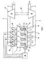
- FIG. 1 comprises a piston engine 1 according to the invention in an engine block 2, at least one cylinder 3.
- four cylinders 3 are provided in series. It is clear that in principle also a different number and / or arrangement of the cylinder 3 is possible.
- the cylinders 3 of the piston engine 1 are supplied via a fresh gas line 4 with fresh gas or with fresh mixture. Exhaust gas is discharged from the cylinders 3 via an exhaust pipe 5. From the fresh gas line 4 individual inlet lines go from 6 to the individual cylinders 3, which can also be referred to as suction pipes.
- the cylinders 3 are connected via individual outlet lines 7 with the exhaust pipe 5 in connection, which can also be referred to as manifold.
- the cylinders 3 are provided with charge exchange valves.
- each cylinder 3 has two intake valves 8 and two exhaust valves, namely a first exhaust valve 9 and a second exhaust valve 10.
- an injection device 11 shown here only in simplified form can cooperate.
- the injection device 11 can be designed such that the fuel can be injected into the respective intake manifold 6 or directly into the cylinder 3 or by a combination of both.
- a spark-ignited piston engine 1 may also have an ignition device shown here only simplified 12 provided and assigned to the cylinders 3.
- the piston engine 1 has a double camshaft 13.
- the two shafts 14, 15 are arranged one inside the other and rotatable relative to each other.
- the inner shaft 14 carries a first cam 16 for each first exhaust valve 9.
- the inner shaft 14 actuates the first exhaust valves 9 via the first cams 16.
- the outer shaft 15 has a second cam 17 for every second exhaust valve 10.
- all the second exhaust valves 10 are controlled by means of the outer shaft 15 via the second cam 17.
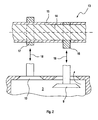
- Fig. 2 shows the interaction of the two shafts 14, 15 and their cams 16, 17 with the two exhaust valves 9, 10 of the cylinder 3.
- the mechanical operating path between the respective cam 16, 17 and the respective outlet valve 9, 10 is simplified by Double arrows 18 indicated.
- the relative position of the two shafts 14, 15 is, for example, adjustable so that the first cams 16 and the second cams 17 actuate the two outlet valves 9, 10 in synchronism with the opening and closing.
- the opening time or the closing time of the first exhaust valve 9 are adjusted either early or late.
- the opening time or the closing time of the second exhaust valve 10 can be either moved to early or late.
- the opening timing of the first-opening exhaust valve 9, 10 constitutes the opening timing of an exhaust-time window.
- the closing time of the last closing exhaust valve 9, 10 forms the closing time of the Auslasszeit1,s.
- an adjusting device 19 is provided which can be controlled by means of a control device 20.
- An adjustment of the inner shaft 14 and the outer shaft 15 relative to the crankshaft can be done with an integrated into the actuator 19 or even with a separate adjusting device.
- the piston engine 1 is additionally equipped with an exhaust gas turbocharger 21, the compressor 22 is integrated into the fresh gas line 4 and the turbine 23 is integrated into the exhaust pipe 5.
- compressor 22 and turbine 23 are drive-coupled with one another via a common shaft 24 and together form the rotor of the exhaust-gas turbocharger 21.
- the control device 20 can control the adjusting device 19 so that it changes the relative position between the shafts 14, 15 so that the opening time of the first Exhaust valve 9 or alternatively the second exhaust valve 10 is moved early in all cylinders 3 according to a first alternative. That is, one of the two exhaust valves 9, 10 opens earlier than in normal operation. As a result, exhaust gas may escape from the respective cylinder 3 at a higher pressure and at a higher temperature than conventional timing. In particular, the respective piston has not reached its bottom dead center at this time, so that the energy content of the gas is still relatively high.
- the control device 20 can control the adjusting device 19 in such a way that it changes the relative position between the shafts 14, 15 so that the opening time of the first outlet valve 9 or alternatively of the second outlet valve 10 is retarded for all cylinders 3 At low speeds or at low loads of the piston engine 1 to cause a rapid response of the turbocharger 21.
- one of the two exhaust valves 9,10 opens later than in normal operation.
- the exhaust gas at higher pressure and at higher temperature over conventional control times escape from the respective cylinder 3.
- the respective piston already has its bottom dead center at this time exceeded, so that by the subsequent recompression of the energy content of the gas is already relatively high again.
- the exhaust gas in both alternatives has a significantly higher enthalpy, which can be converted into kinetic energy at the turbine 23. Accordingly, the turbine 23 can accelerate relatively quickly, whereby the startup of the turbocharger 21 is shortened accordingly.
- all the cylinders 3 of the piston engine 1 are equipped with two outlet valves 9, 10, which can each be controlled separately via the two shafts 14, 15 of the double camshaft 13.
- the number of cylinders 3, the two exhaust valves 9, 10 which are separately controllable via the two shafts 14, 15 of the double camshaft 13, smaller than the total number of cylinders 3 of the piston engine 1.
- the other cylinder 3 may then each have only one or more exhaust valves, which, however, are all controlled only via the inner shaft 14 or alternatively only via the outer shaft 15.
- not all cylinders 3, the exhaust gas is removed earlier, but for example, only one cylinder 3 or only two cylinders 3, at least one compared to the total number of cylinders 3 reduced cylinder number for accelerating the exhaust gas turbocharger.
- the transferable to the crankshaft of the reciprocating engine power 1 by the earlier or later opening of the respective exhaust valve 9, 10 is not so greatly reduced, as in the previously described embodiment, in which the exhaust gas of all cylinders 3 is temporarily removed at an increased cylinder pressure.
- Fig. 3 and 4 show further embodiments of the in Fig. 1 shown piston engine 1, however, for simplicity, the injection device 11 and the ignition device 12 are omitted.
- the piston engine 1 may have at least one fast-switching valve 29. This is arranged upstream of the intake valves 8 in a fresh gas line leading the piston engine 1.
- a fast-switching valve 29 is understood to mean a valve 29 which, in particular, achieves similar switching times when switching between a closed state and an open state or from an open state to a closed state, such as the gas exchange valves 8, 9, 10 29, which are also referred to as Frischgasventile 29 due to their arrangement in the fresh gas tract, achieve switching times that are less than 10 ms.
- the fresh gas valves 29 can work with a flap, which is symbolically indicated here and is discontinuously switchable between a closed position and an open position. Likewise, continuously operating fresh gas valves 29 are conceivable in which the flap or a rotary valve or any other valve member rotates with a constant direction of rotation and thereby also allows corresponding switching times. Discontinuous, Quick-switching valves 29 may also be referred to as air timing valves.
- each cylinder 3 a separate fresh gas valve 29 assigned.
- the individual fresh gas valves 29 are arranged in the suction pipes 6.
- the fresh gas valves 29 can be actuated by a corresponding control device.
- this control device is integrated into the already existing control device 20.
- a separate control device for actuating the fresh gas valves 29 may also be provided.
- the respective control device 20 can now be designed such that it actuates the respective fresh gas valve 29 as a function of a current operating state of the piston engine 1.
- the control device 20 may be coupled to a conventional engine control unit, not shown here. In this case, it is basically possible to integrate the controller 20 shown in the hardware in the mentioned engine control unit and / or to implement it in the software in said engine control unit.
- the control device 20 can control the respective fresh gas valve 29, for example, to realize a pulse charging of the cylinder 3.
- a pulse-type fresh gas stream can be generated with the aid of the one fresh gas valve 29 or with the aid of the fresh gas valves 29 be generated in the manner of a pressure wave, which is introduced during the charge exchange process in the respective cylinder 3.
- the fresh charge mass introduced into the cylinders 3 can be increased.
- Such a pulse charging can be used particularly advantageous when the turbocharger 21 is virtually inactive due to low engine speeds and engine loads or allows no significant pressure increase in the fresh gas.
- a cold charge can be realized according to the so-called Miller method, which allows an improvement of the pollutant emissions.
- a de-throttling of the fresh gas system or the piston engine 1 in the partial load can be realized.
- the fresh gas valve 29 itself is not a throttle. With a throttle, the flow-through cross section can be varied or throttled quasi steplessly in the fresh gas line.
- a de-throttled load control can be realized by means of filling variation without the use of a throttle.
- the fresh gas passes unthrottled, ie without the use of a throttle or the like to the cylinders 3, which ultimately the efficiency of the piston engine 1 improved.
- the fresh gas flow can be easily turned off as soon as the desired filling in each cylinder 3 is reached.
- the fresh gas line 4 or the complete fresh gas system unthrottled or throttled, ie without a special, the throttling serving throttle element.
- the control device 20 or a suitable other control device can cooperate with the injection device 11 in such a way that the injection timing and / or spark-ignition engines also apply to this case the ignition timing in the respective cylinder 3 is displaced in a suitable manner such that a higher exhaust gas enthalpy than a conventional center of gravity results due to a late combustion center of gravity.
- the controller 20 or any other suitable control with the ignition device 12 cooperate, such that for accelerating the exhaust gas turbocharger 21, the ignition is shifted in a suitable manner.
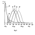
- FIG. 5 shows a diagram whose ordinate a pressure P in a cylinder 3 and a stroke H of the two exhaust valves 9, 10 of this cylinder 3 are plotted and the abscissa represents the associated crankshaft angle KW.
- the diagram contains an exemplary curve 25 of the pressure P in the cylinder 3 as a function of the crankshaft angle KW, as would result from conventional exhaust valve control times.
- the diagram includes a profile 26 of the stroke H of the first exhaust valve 9 and a curve 27 of the stroke H of the second exhaust valve 10.
- the two Hubverêt 26, 27 are plotted as a function of the crankshaft angle KW.
- the two exhaust valves 9, 10 are controlled simultaneously.
- the corresponding cams 16, 17 are provided for this purpose with identical control contours to obtain identical courses 26, 27.
- the two courses 26, 27 are congruent with synchronous operation and correspond to in Fig. 5 the exemplary curve 26 of the first exhaust valve 9. That means that both exhaust valves 9, 10 at a crankshaft angle of about 120 ° relative to the here at 0 ° CA lying top dead center OT H begin their opening movement, so that they at bottom dead center UT LW of the associated piston, which corresponds to 180 ° KW relative to TDC H , are already largely open. Their own maximum opening, the exhaust valves 9, 10 then at 240 ° CA based on OT H.
- the turbocharger 21 is to be raised in the shortest possible time, so that it is characterized by a short response time, the relative position between the inner shaft 14 and the outer shaft 15 is changed by a corresponding actuation of the double camshaft 13 so that second exhaust valve 10 is shifted early in terms of its opening time.
- this is recognizable by the fact that the stroke profile 27 associated with the second outlet valve 10 is displaced in the direction of smaller crankshaft angles KW by, for example, 60 ° CA according to an arrow 30. This means that the second exhaust valve 10 starts at 60 ° CA relative to TDC H with its opening movement.
- control device 20 may set the opening time of the one exhaust valve 9, 10, in the example of the second exhaust valve 10, to a range which is expediently between 30% and 90% of an expansion stroke of the associated piston. In the example shown, the opening time is shifted from 2/3 to 1/3 of the expansion stroke.
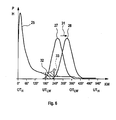
- Fig. 6 again shows a diagram on the ordinate a pressure P in a cylinder 3 and a stroke H of the two exhaust valves 9, 10 of this cylinder 3 are plotted, and the abscissa represents the associated crankshaft angle KW.
- the diagram contains an exemplary curve 25 of the pressure P in the cylinder 3 as a function of the crankshaft angle KW, as would result from conventional exhaust valve control times.
- the diagram contains a profile 26 of the stroke H of the first Exhaust valve 9 and a curve 27 of the stroke H of the second exhaust valve 10.
- the two Hubverêt 26, 27 are plotted as a function of the crankshaft angle KW.
- the two exhaust valves 9, 10 are driven asynchronously.
- the two courses 26, 27 are formed identically, which can be realized by cams 16, 17 with identical control contours.
- this is not mandatory.
- the course 27 of the second exhaust valve 10 is positioned in time in the example before the course 26 of the first exhaust valve 9. That is, the second exhaust valve 10 opens in normal operation before the first exhaust valve 9.
- the control contours of the cams 16, 17 are shaped such that the courses 26, 27 of the outlet valves 9, 10 each have an opening time window of approximately 240 ° CA, as shown in FIGS Fig.
- curves 26, 27 special embodiments that allow smaller opening time window.
- the control contours of the cams 16, 17 are formed so that the opening time window of the two exhaust valves 9, 10 are each only about 180 °.
- other opening time windows are conceivable, which are smaller than 240 ° CA.
- opening time windows are also conceivable which are smaller than 180 ° CA.
- the second exhaust valve 10 begins according to its course 27 at a crankshaft angle of about 180 ° relative to the top dead center OT H lying here at 0 ° KW with its opening movement, ie approximately in the region of a bottom dead center UT LW of the associated piston. Its maximum opening has the second exhaust valve 10 at about 270 ° CA based on OT H. The second exhaust valve 10 closes at about 360 ° CA based on OT H.
- the course 27, which can also be referred to as outlet lift curve 27, thus has an opening time window of about 180 ° CA.
- the profile 26 of the first exhaust valve 9, which may also be referred to as outlet lift curve 26, is offset in the example by about 60 ° CA compared to the outlet lift curve 27 of the second valve in the example. Accordingly, the first exhaust valve 9 opens in normal operation at about 240 ° CA, has its maximum opening width at about 330 ° CA and closes at about 420 ° KW. Thus, the second Auslasserhebungskurve 26 has an opening time window of about 180 ° KW. Due to the overlapping opening time windows, a total exhaust time window is defined for the respective cylinder, which has approximately 240 ° CA.
- the opening time window in normal operation in both alternatives is about the same size.
- the positioning the Auslasszeitmut or the two courses 26, 27 of the second alternative corresponds to the course 26 'of a conventional exhaust valve shown with a broken line.
- the turbocharger 21 is to be raised in the shortest possible time, so that it is characterized by a short response time, the relative position between the inner shaft 14 and the outer shaft 15 is changed by a corresponding actuation of the double camshaft 13 so that the second Outlet valve 10 is moved late in terms of its opening time.
- this is recognizable by the fact that the stroke profile 27 associated with the second outlet valve 10 is displaced in the direction of greater crankshaft angle KW by, for example, 60 ° CA in accordance with an arrow 31. This means that the second exhaust valve 10 then begins at 240 ° CA relative to TDC H with its opening movement.
- a hatched area 32 within the pressure curve 25 and within a modified pressure curve 33 is marked.
- the modified pressure curve 33 results from the fact that the opening time of the Auslasszeit varieties in the example shown is in time after the bottom dead center UT LW , so that the respective piston is already moving again in its compression direction. Accordingly, in the respective cylinder during this recompression phase, the pressure rises as well as the temperature in the exhaust gas again.
- the hatched area 32 symbolizes, by way of example, the exhaust-gas enthalpy additionally provided with respect to a second exhaust valve 10 which has not been retarded. The exhaust gas flow reaches the exhaust pipe 5 through the later-opened second exhaust valve 10 and can be used to accelerate the turbine 23.
- the control device 20 may set the opening time of the one outlet valve 9, 10, in the example of the second outlet valve 10, to a range which is expediently between 0% and 30% of a recompression stroke of the associated piston.
- the opening time of UT LW becomes about one-third of the recompression stroke postponed.
- the outlet elevation curve 26 of the first outlet valve 9 is already in this area in the example, ie, the first outlet valve 9 opens late in normal operation relative to UT LW , ie in the recompression phase.
Landscapes
- Engineering & Computer Science (AREA)
- Mechanical Engineering (AREA)
- General Engineering & Computer Science (AREA)
- Chemical & Material Sciences (AREA)
- Combustion & Propulsion (AREA)
- Supercharger (AREA)
- Output Control And Ontrol Of Special Type Engine (AREA)
- Valve Device For Special Equipments (AREA)
Abstract
Claims (10)
- Moteur à pistons, en particulier pour un véhicule automobile, comprenant- au moins un cylindre (3) qui présente au moins deux soupapes d'échappement (9, 10),- un double arbre à cames (13) pour commander lesdites soupapes d'échappement (9, 10),- ledit double arbre à cames (13) présentant un arbre intérieur (14) avec au moins une première came (16) de commande de la première soupape d'échappement (9) respective ainsi qu'un arbre extérieur (15) coaxial à ce premier, avec au moins une deuxième came (17) de commande de la deuxième soupape d'échappement (10) respective,- ledit arbre intérieur (14) et ledit arbre extérieur (15) étant réglables en rotation l'un par rapport à l'autre pour modifier l'intervalle de temps d'échappement des soupapes d'échappement (9, 10),
caractérisé par le fait- que l'on prévoit un turbocompresseur à gaz d'échappement (21) dont la turbine (23) est disposée dans une conduite de gaz d'échappement (5) du moteur à pistons (1).- que l'on prévoit un dispositif de commande (20) pour commander un dispositif de réglage (19) destiné à régler en rotation la position relative de rotation entre lesdits arbres (14, 15),- que, pour accélérer la turbine (23), ledit dispositif de commande (20) fait reporter vers tôt ou vers tard le moment d'ouverture de la première soupape d'échappement (9) respective ou de la deuxième soupape d'échappement (10) respective,- que ledit dispositif de commande (20), soit,- pour accélérer la turbine (23), fait situer le moment d'ouverture de la soupape d'échappement (9, 10) respective dans une plage comprise entre 30 % et 90 % de la course d'expansion d'un piston réglable en course dans le cylindre associé (3), le dispositif de commande (20), pour un fonctionnement normal, actionnant les deux soupapes d'échappement (9, 10) de manière à ce qu'elles s'ouvrent en synchronisme, soit,- pour un fonctionnement normal, il actionne l'une des soupapes d'échappement (9, 10) de manière à ce qu'elle s'ouvre plus tôt que l'autre soupape d'échappement (9, 10) dont le moment d'ouverture se situe dans une course de recompression du piston réglable en course dans le cylindre associé (3), le dispositif de commande (20), pour accélérer ladite turbine (23), faisant reporter vers tard le moment d'ouverture de la soupape d'échappement (9, 10) qui, en fonctionnement normal, s'ouvre plus tôt, et ceci jusqu'à ce que les deux soupapes d'échappement (9, 10) s'ouvrent en synchronisme. - Moteur à pistons selon la revendication 1, caractérisé par le fait que les intervalles de temps d'ouverture des deux soupapes d'échappement (9, 10) sont chacun inférieurs à 240° d'angle de vilebrequin ou inférieurs à 200° d'angle de vilebrequin ou inférieurs à 180° d'angle de vilebrequin.
- Moteur à pistons selon la revendication 1 ou 2, caractérisé par le fait que tous les cylindres (3) du moteur à pistons (1) comprennent deux soupapes d'échappement (9, 10) qui peuvent être commandées séparément via les deux arbres (14, 15) du double arbre à cames (13).
- Moteur à pistons selon la revendication 1 ou 2, caractérisé par le fait que le nombre des cylindres (3) dont les deux soupapes d'échappement (9, 10) peuvent être commandées séparément via les deux arbres (14, 15) du double arbre à cames (13) est inférieur au nombre total des cylindres (3) du moteur à pistons (1).
- Moteur à pistons selon l'une quelconque des revendications 1 à 4, caractérisé par le fait- que l'on prévoit au moins une soupape à action rapide (29) qui est agencée en amont de soupapes d'admission (8) associées aux cylindres (3), dans une conduite de gaz frais (4, 6) du moteur à pistons (1), et/ou- que l'on prévoit un dispositif de commande (20) pour commander ladite au moins une soupape (29), et/ou- que, soit, à chaque cylindre (3) est associée une soupape séparée à action rapide (29), soit à l'ensemble des cylindres (3) est associée une soupape commune à action rapide (29).
- Moteur à pistons selon la revendication 5, caractérisé par le fait que ledit dispositif de commande (20) commande la soupape respective (29) en fonction d'un état actuel de fonctionnement du moteur à pistons (1) pour réaliser une suralimentation par impulsions et/ou une suppression d'étranglement et/ou une charge froide et/ou une charge thermique.
- Moteur à pistons selon l'une quelconque des revendications 1 à 6, caractérisé par le fait qu'une conduite de gaz frais (4) qui amène du gaz frais aux cylindres (3) est non étranglée ou dépourvue d'étranglement.
- Moteur à pistons selon l'une quelconque des revendications 1 à 7, caractérisé par le fait- que l'on prévoit un dispositif d'injection (11) pour injecter du carburant dans le cylindre respectif (3),- que l'on prévoit un dispositif de commande (20) pour commander ledit dispositif d'injection (11),- que, pour accélérer la turbine (23), ledit dispositif de commande (20) fait reporter le moment d'injection.
- Moteur à pistons selon la revendication 8, caractérisé par le fait que, pour accélérer la turbine (23) dans un moteur (1) à allumage automatique, ledit dispositif de commande (20) fait reporter vers tard, par une injection multiple, la position de centre de gravité de combustion pour augmenter l'enthalpie des gaz d'échappement par rapport à une position de centre de gravité conventionnelle.
- Moteur à pistons selon l'une quelconque des revendications 1 à 9, caractérisé par le fait- que l'on prévoit un dispositif d'allumage (12) pour allumer un mélange carburant/gaz frais dans le cylindre respectif (3),- que l'on prévoit un dispositif de commande (20) pour commander ledit dispositif d'allumage (12),- que, pour accélérer la turbine (23), ledit dispositif de commande (20) fait reporter le moment d'allumage.
Applications Claiming Priority (2)
| Application Number | Priority Date | Filing Date | Title |
|---|---|---|---|
| DE102007042053A DE102007042053A1 (de) | 2007-09-05 | 2007-09-05 | Kolbenmotor |
| PCT/EP2008/061587 WO2009030694A2 (fr) | 2007-09-05 | 2008-09-03 | Moteur à piston |
Publications (2)
| Publication Number | Publication Date |
|---|---|
| EP2183469A2 EP2183469A2 (fr) | 2010-05-12 |
| EP2183469B1 true EP2183469B1 (fr) | 2012-06-27 |
Family
ID=40229990
Family Applications (1)
| Application Number | Title | Priority Date | Filing Date |
|---|---|---|---|
| EP08803558A Not-in-force EP2183469B1 (fr) | 2007-09-05 | 2008-09-03 | Moteur à piston |
Country Status (5)
| Country | Link |
|---|---|
| US (1) | US8857177B2 (fr) |
| EP (1) | EP2183469B1 (fr) |
| CN (1) | CN101796268B (fr) |
| DE (1) | DE102007042053A1 (fr) |
| WO (1) | WO2009030694A2 (fr) |
Cited By (1)
| Publication number | Priority date | Publication date | Assignee | Title |
|---|---|---|---|---|
| DE102015200517B3 (de) * | 2015-01-15 | 2016-03-03 | Ford Global Technologies, Llc | Verfahren und System zum Betreiben eines aufgeladenen Verbrennungsmotors eines Kraftfahrzeugs |
Families Citing this family (8)
| Publication number | Priority date | Publication date | Assignee | Title |
|---|---|---|---|---|
| DE102009060211A1 (de) * | 2009-12-23 | 2011-06-30 | MAHLE International GmbH, 70376 | Brennkraftmaschine und zugehöriges Betriebsverfahren |
| EP2636874B1 (fr) * | 2010-11-04 | 2017-04-19 | Toyota Jidosha Kabushiki Kaisha | Dispositif de commande pour moteur thermique |
| EP2639430A4 (fr) * | 2010-11-08 | 2014-03-26 | Toyota Motor Co Ltd | Moteur |
| DE102011081844A1 (de) | 2011-08-31 | 2013-02-28 | Ford Global Technologies, Llc | Verfahren zum Betreiben einer aufgeladenen Brennkraftmaschine und Brennkraftmaschine zur Durchführung eines derartigen Verfahrens |
| DE102011084834A1 (de) * | 2011-10-20 | 2013-04-25 | Ford Global Technologies, Llc | Brennkraftmaschine mit mehreren Auslaßöffnungen je Zylinder und Ladungswechselverfahren für eine derartige Brennkraftmaschine |
| DE102014015649A1 (de) * | 2014-10-24 | 2016-04-28 | Thyssenkrupp Presta Teccenter Ag | Verfahren zum Herstellen einer verstellbaren Nockenwelle und verstellbare Nockenwelle |
| CN106930850B (zh) * | 2015-12-29 | 2020-07-03 | 长城汽车股份有限公司 | 双燃料发动机系统及其控制方法、车辆 |
| DE102016217265A1 (de) * | 2016-09-09 | 2018-03-15 | Volkswagen Aktiengesellschaft | Brennkraftmaschine und Verfahren zum Betreiben einer Brennkraftmaschine |
Family Cites Families (38)
| Publication number | Priority date | Publication date | Assignee | Title |
|---|---|---|---|---|
| GB2185286A (en) | 1986-01-11 | 1987-07-15 | Fleming Thermodynamics Ltd | I.C. engine with an exhaust gas driven turbine or positive displacement expander |
| DE3624827A1 (de) * | 1986-07-23 | 1988-02-04 | Sueddeutsche Kolbenbolzenfabri | Verstelleinrichtung fuer eine nockenwelle zum steuern der gasein- und auslassventile von verbrennungsmotoren |
| DE3821935A1 (de) * | 1988-06-29 | 1990-02-08 | Audi Ag | Ventilgesteuerte brennkraftmaschine |
| IT9020789A1 (it) * | 1989-07-04 | 1991-01-05 | Gkn Automotive Ag | Albero a camme |
| DE3934848A1 (de) * | 1989-10-19 | 1991-04-25 | Ingelheim Peter Graf Von | In zwei und mehr groessen separat mit nur einem regelorgan verstellbare nockenwelle |
| DE3943426C1 (fr) * | 1989-12-22 | 1991-04-11 | Gkn Automotive Ag, 5200 Siegburg, De | |
| US5230320A (en) * | 1991-06-27 | 1993-07-27 | Mazda Motor Corporation | Intake and exhaust control system for automobile engine |
| JPH05263671A (ja) | 1992-03-23 | 1993-10-12 | Toyota Motor Corp | ターボ過給機付内燃機関のバルブタイミング制御装置 |
| SE507030C2 (sv) * | 1992-09-11 | 1998-03-16 | Saab Automobile | Avgasflödessystem för en med överladdare försedd förbränningsmotor, samt vid dylikt system tillämpat förfarande |
| JPH06323158A (ja) | 1993-05-13 | 1994-11-22 | Isuzu Ceramics Kenkyusho:Kk | ターボコンパウンドエンジン |
| US5417186A (en) * | 1993-06-28 | 1995-05-23 | Clemson University | Dual-acting apparatus for variable valve timing and the like |
| GB9325168D0 (en) * | 1993-12-08 | 1994-02-09 | Frost Derek | Variable valve timing |
| FR2744170B1 (fr) * | 1996-01-26 | 1998-04-17 | Tacquet Maurice Andre | Moteur diesel a quatre temps suralimente par turbocompresseur avec variation du calage des cames |
| SE514969C2 (sv) * | 1999-09-15 | 2001-05-21 | Saab Automobile | Förbränningsmotor |
| FR2815082B1 (fr) * | 2000-10-09 | 2003-04-11 | Inst Francais Du Petrole | Procede de controle d'auto-allumage dans un moteur a quatre temps |
| GB2369175A (en) * | 2000-11-18 | 2002-05-22 | Mechadyne Plc | Variable phase coupling |
| CN2512912Y (zh) * | 2001-04-27 | 2002-09-25 | 长安汽车(集团)有限责任公司 | 多气门配气机构 |
| DE102004020124A1 (de) | 2004-04-24 | 2005-11-17 | Aft Atlas Fahrzeugtechnik Gmbh | Vorrichtung zur Einstellung von Ventilsteuerzeiten sowie Brennkraftmaschine mit einer derartigen Vorrichtung |
| US7308872B2 (en) * | 2004-12-30 | 2007-12-18 | Delphi Technologies, Inc. | Method and apparatus for optimized combustion in an internal combustion engine utilizing homogeneous charge compression ignition and variable valve actuation |
| FR2886342B1 (fr) * | 2005-05-24 | 2010-08-27 | Inst Francais Du Petrole | Procede de controle du balayage des gaz brules d'un moteur a injection indirecte, notamment moteur suralimente, et moteur utilisant un tel procede |
| DE102005031241A1 (de) * | 2005-07-01 | 2007-01-04 | Fev Motorentechnik Gmbh | Variabler Ventiltrieb einer Kolben-Brennkraftmaschine |
| JP4244979B2 (ja) * | 2005-09-22 | 2009-03-25 | トヨタ自動車株式会社 | 内燃機関の過給圧制御装置 |
| GB2431977A (en) * | 2005-11-02 | 2007-05-09 | Mechadyne Plc | Camshaft assembly |
| DE102006014965A1 (de) * | 2006-03-31 | 2007-10-11 | Volkswagen Ag | Brennkraftmaschine und Verfahren zum Betreiben dieser |
| FR2902833A1 (fr) * | 2006-06-21 | 2007-12-28 | Peugeot Citroen Automobiles Sa | Procede pour commander un moteur a combustion interne |
| US20080066715A1 (en) * | 2006-09-15 | 2008-03-20 | Mrdjan Jankovic | Control of Air-Charge and Cylinder Air Temperature in Engine |
| JP4955020B2 (ja) * | 2007-02-09 | 2012-06-20 | 耕一 畑村 | 4サイクルエンジン |
| US8534261B2 (en) * | 2007-05-09 | 2013-09-17 | Hatamura Engine Research Office Ltd. | Four-cycle engine |
| EP2522820B1 (fr) * | 2007-07-02 | 2017-08-09 | BorgWarner Inc. | Came concentrique avec clapets anti-retour dans la bobine pour un déphaseur |
| JP4623064B2 (ja) * | 2007-08-13 | 2011-02-02 | トヨタ自動車株式会社 | 過給機付き内燃機関の制御装置 |
| JP2009085022A (ja) * | 2007-09-27 | 2009-04-23 | Toyota Motor Corp | 車両の制御装置 |
| WO2009105463A2 (fr) * | 2008-02-22 | 2009-08-27 | Borgwarner Inc. | Commande d'un écoulement de gaz d'échappement divisé entre une turbocompression et une remise en circulation de gaz d'échappement |
| US8065878B2 (en) * | 2008-03-10 | 2011-11-29 | Deere & Company | Two phase exhaust for internal combustion engine |
| JP4609541B2 (ja) * | 2008-07-18 | 2011-01-12 | トヨタ自動車株式会社 | 過給機付き内燃機関の制御装置 |
| US7997237B2 (en) * | 2008-09-10 | 2011-08-16 | Ford Global Technologies, Llc | Multi-stroke internal combustion engine |
| GB2467943A (en) * | 2009-02-23 | 2010-08-25 | Mechadyne Plc | I.c. engine double overhead camshaft phasing system |
| US8590507B2 (en) * | 2009-09-30 | 2013-11-26 | GM Global Technology Operations LLC | Variable valve actuation control systems and methods |
| JP4883330B2 (ja) * | 2009-11-25 | 2012-02-22 | 三菱自動車工業株式会社 | 内燃機関の可変動弁装置 |
-
2007
- 2007-09-05 DE DE102007042053A patent/DE102007042053A1/de not_active Withdrawn
-
2008
- 2008-09-03 WO PCT/EP2008/061587 patent/WO2009030694A2/fr not_active Ceased
- 2008-09-03 US US12/676,445 patent/US8857177B2/en not_active Expired - Fee Related
- 2008-09-03 EP EP08803558A patent/EP2183469B1/fr not_active Not-in-force
- 2008-09-03 CN CN2008801052400A patent/CN101796268B/zh not_active Expired - Fee Related
Cited By (1)
| Publication number | Priority date | Publication date | Assignee | Title |
|---|---|---|---|---|
| DE102015200517B3 (de) * | 2015-01-15 | 2016-03-03 | Ford Global Technologies, Llc | Verfahren und System zum Betreiben eines aufgeladenen Verbrennungsmotors eines Kraftfahrzeugs |
Also Published As
| Publication number | Publication date |
|---|---|
| US8857177B2 (en) | 2014-10-14 |
| WO2009030694A2 (fr) | 2009-03-12 |
| EP2183469A2 (fr) | 2010-05-12 |
| CN101796268B (zh) | 2013-06-12 |
| DE102007042053A1 (de) | 2009-03-12 |
| WO2009030694A3 (fr) | 2009-06-18 |
| CN101796268A (zh) | 2010-08-04 |
| US20100242472A1 (en) | 2010-09-30 |
Similar Documents
| Publication | Publication Date | Title |
|---|---|---|
| EP2183469B1 (fr) | Moteur à piston | |
| EP2048331B1 (fr) | Moteur à combustion interne doté d'arbres à came mixtes | |
| EP2049779B1 (fr) | Moteur à combustion | |
| EP3610147B1 (fr) | Procédé pour faire fonctionner un moteur à combustion interne et moteur à combustion interne | |
| DE102011084834A1 (de) | Brennkraftmaschine mit mehreren Auslaßöffnungen je Zylinder und Ladungswechselverfahren für eine derartige Brennkraftmaschine | |
| DE10359267B4 (de) | Verbrennungsmotor mit Ansaugventilen, variabler Ventilbetätigung und Zeitsteuerung | |
| DE102016209957A1 (de) | Verfahren zum Betreiben einer Brennkraftmaschine und Brennkraftmaschine | |
| EP1331382B1 (fr) | Procédé, programme informatique et appareil de commande et/ou regulation destinés à l'utilisation d'un moteur à combustion interne, et moteur à combustion interne | |
| EP2643570A2 (fr) | Procédé de fonctionnement | |
| EP3008300B1 (fr) | Moteur a combustion interne et procédé pour changer le mode de fonctionnement du moteur et passer d'un fonctionnement normal à un mode de fonctionnement avec balayage | |
| WO2017102042A1 (fr) | Procédé de fonctionnement d'un moteur à combustion interne à pistons alternatifs | |
| DE102009015639A1 (de) | Brennkraftmaschine und zugehöriges Betriebsverfahren | |
| DE102014208950A1 (de) | Verbrennungsmotor und Verfahren zum Betreiben eines solchen Verbrennungsmotors | |
| EP1306527B1 (fr) | Moteur diesel à rapport de compression variable | |
| EP1333158B1 (fr) | Moteur à quatre temps à injection directe et procédé de commande des soupapes | |
| EP1840352B1 (fr) | Système d'alimentation d'air frais et méthode d'opération pour un moteur à piston | |
| EP2976512B1 (fr) | Moteur à combustion interne et procédé pour le faire fonctionner | |
| DE102021005647A1 (de) | Verfahren zum Betreiben einer Verbrennungskraftmaschine, insbesondere eines Kraftfahrzeugs | |
| WO2013143687A1 (fr) | Procédé pour faire fonctionner un moteur à combustion interne | |
| EP1741904B1 (fr) | Procédé de commande d'un moteur à quatre temps à allumage par étincelle comprenant une commande de soupape variable | |
| EP2532860B1 (fr) | Moteur à combustion interne | |
| EP1657420A1 (fr) | Moteur à combustion interne et méthode pour contrôler l'arrêt d'un moteur à combustion interne | |
| DE102015200598A1 (de) | Fremdgezündete Brennkraftmaschine mit variablem Ventiltrieb und Verfahren zum Betreiben einer derartigen Brennkraftmaschine | |
| DE202015106072U1 (de) | Brennkraftmaschine mit variablem Ventiltrieb | |
| DE102013215764A1 (de) | Hubkolbenbrennkraftmaschine sowie Verfahren zur Steuerung der Einlassseite einer Hubkolbenbrennkraftmaschine |
Legal Events
| Date | Code | Title | Description |
|---|---|---|---|
| PUAI | Public reference made under article 153(3) epc to a published international application that has entered the european phase |
Free format text: ORIGINAL CODE: 0009012 |
|
| 17P | Request for examination filed |
Effective date: 20100202 |
|
| AK | Designated contracting states |
Kind code of ref document: A2 Designated state(s): AT BE BG CH CY CZ DE DK EE ES FI FR GB GR HR HU IE IS IT LI LT LU LV MC MT NL NO PL PT RO SE SI SK TR |
|
| AX | Request for extension of the european patent |
Extension state: AL BA MK RS |
|
| 17Q | First examination report despatched |
Effective date: 20101105 |
|
| GRAP | Despatch of communication of intention to grant a patent |
Free format text: ORIGINAL CODE: EPIDOSNIGR1 |
|
| DAX | Request for extension of the european patent (deleted) | ||
| GRAS | Grant fee paid |
Free format text: ORIGINAL CODE: EPIDOSNIGR3 |
|
| GRAA | (expected) grant |
Free format text: ORIGINAL CODE: 0009210 |
|
| AK | Designated contracting states |
Kind code of ref document: B1 Designated state(s): AT BE BG CH CY CZ DE DK EE ES FI FR GB GR HR HU IE IS IT LI LT LU LV MC MT NL NO PL PT RO SE SI SK TR |
|
| REG | Reference to a national code |
Ref country code: GB Ref legal event code: FG4D Free format text: NOT ENGLISH |
|
| REG | Reference to a national code |
Ref country code: CH Ref legal event code: EP |
|
| REG | Reference to a national code |
Ref country code: AT Ref legal event code: REF Ref document number: 564370 Country of ref document: AT Kind code of ref document: T Effective date: 20120715 |
|
| REG | Reference to a national code |
Ref country code: IE Ref legal event code: FG4D Free format text: LANGUAGE OF EP DOCUMENT: GERMAN |
|
| REG | Reference to a national code |
Ref country code: DE Ref legal event code: R096 Ref document number: 502008007613 Country of ref document: DE Effective date: 20120823 |
|
| PG25 | Lapsed in a contracting state [announced via postgrant information from national office to epo] |
Ref country code: FI Free format text: LAPSE BECAUSE OF FAILURE TO SUBMIT A TRANSLATION OF THE DESCRIPTION OR TO PAY THE FEE WITHIN THE PRESCRIBED TIME-LIMIT Effective date: 20120627 Ref country code: NO Free format text: LAPSE BECAUSE OF FAILURE TO SUBMIT A TRANSLATION OF THE DESCRIPTION OR TO PAY THE FEE WITHIN THE PRESCRIBED TIME-LIMIT Effective date: 20120927 Ref country code: SE Free format text: LAPSE BECAUSE OF FAILURE TO SUBMIT A TRANSLATION OF THE DESCRIPTION OR TO PAY THE FEE WITHIN THE PRESCRIBED TIME-LIMIT Effective date: 20120627 Ref country code: LT Free format text: LAPSE BECAUSE OF FAILURE TO SUBMIT A TRANSLATION OF THE DESCRIPTION OR TO PAY THE FEE WITHIN THE PRESCRIBED TIME-LIMIT Effective date: 20120627 |
|
| REG | Reference to a national code |
Ref country code: NL Ref legal event code: VDEP Effective date: 20120627 |
|
| REG | Reference to a national code |
Ref country code: LT Ref legal event code: MG4D Effective date: 20120627 |
|
| PG25 | Lapsed in a contracting state [announced via postgrant information from national office to epo] |
Ref country code: HR Free format text: LAPSE BECAUSE OF FAILURE TO SUBMIT A TRANSLATION OF THE DESCRIPTION OR TO PAY THE FEE WITHIN THE PRESCRIBED TIME-LIMIT Effective date: 20120627 Ref country code: LV Free format text: LAPSE BECAUSE OF FAILURE TO SUBMIT A TRANSLATION OF THE DESCRIPTION OR TO PAY THE FEE WITHIN THE PRESCRIBED TIME-LIMIT Effective date: 20120627 Ref country code: SI Free format text: LAPSE BECAUSE OF FAILURE TO SUBMIT A TRANSLATION OF THE DESCRIPTION OR TO PAY THE FEE WITHIN THE PRESCRIBED TIME-LIMIT Effective date: 20120627 Ref country code: GR Free format text: LAPSE BECAUSE OF FAILURE TO SUBMIT A TRANSLATION OF THE DESCRIPTION OR TO PAY THE FEE WITHIN THE PRESCRIBED TIME-LIMIT Effective date: 20120928 |
|
| PG25 | Lapsed in a contracting state [announced via postgrant information from national office to epo] |
Ref country code: CY Free format text: LAPSE BECAUSE OF FAILURE TO SUBMIT A TRANSLATION OF THE DESCRIPTION OR TO PAY THE FEE WITHIN THE PRESCRIBED TIME-LIMIT Effective date: 20120627 Ref country code: EE Free format text: LAPSE BECAUSE OF FAILURE TO SUBMIT A TRANSLATION OF THE DESCRIPTION OR TO PAY THE FEE WITHIN THE PRESCRIBED TIME-LIMIT Effective date: 20120627 Ref country code: SK Free format text: LAPSE BECAUSE OF FAILURE TO SUBMIT A TRANSLATION OF THE DESCRIPTION OR TO PAY THE FEE WITHIN THE PRESCRIBED TIME-LIMIT Effective date: 20120627 Ref country code: IS Free format text: LAPSE BECAUSE OF FAILURE TO SUBMIT A TRANSLATION OF THE DESCRIPTION OR TO PAY THE FEE WITHIN THE PRESCRIBED TIME-LIMIT Effective date: 20121027 Ref country code: CZ Free format text: LAPSE BECAUSE OF FAILURE TO SUBMIT A TRANSLATION OF THE DESCRIPTION OR TO PAY THE FEE WITHIN THE PRESCRIBED TIME-LIMIT Effective date: 20120627 Ref country code: RO Free format text: LAPSE BECAUSE OF FAILURE TO SUBMIT A TRANSLATION OF THE DESCRIPTION OR TO PAY THE FEE WITHIN THE PRESCRIBED TIME-LIMIT Effective date: 20120627 |
|
| PG25 | Lapsed in a contracting state [announced via postgrant information from national office to epo] |
Ref country code: PT Free format text: LAPSE BECAUSE OF FAILURE TO SUBMIT A TRANSLATION OF THE DESCRIPTION OR TO PAY THE FEE WITHIN THE PRESCRIBED TIME-LIMIT Effective date: 20121029 Ref country code: PL Free format text: LAPSE BECAUSE OF FAILURE TO SUBMIT A TRANSLATION OF THE DESCRIPTION OR TO PAY THE FEE WITHIN THE PRESCRIBED TIME-LIMIT Effective date: 20120627 Ref country code: IT Free format text: LAPSE BECAUSE OF FAILURE TO SUBMIT A TRANSLATION OF THE DESCRIPTION OR TO PAY THE FEE WITHIN THE PRESCRIBED TIME-LIMIT Effective date: 20120627 |
|
| PG25 | Lapsed in a contracting state [announced via postgrant information from national office to epo] |
Ref country code: NL Free format text: LAPSE BECAUSE OF FAILURE TO SUBMIT A TRANSLATION OF THE DESCRIPTION OR TO PAY THE FEE WITHIN THE PRESCRIBED TIME-LIMIT Effective date: 20120627 |
|
| BERE | Be: lapsed |
Owner name: MAHLE INTERNATIONAL G.M.B.H. Effective date: 20120930 |
|
| PG25 | Lapsed in a contracting state [announced via postgrant information from national office to epo] |
Ref country code: ES Free format text: LAPSE BECAUSE OF FAILURE TO SUBMIT A TRANSLATION OF THE DESCRIPTION OR TO PAY THE FEE WITHIN THE PRESCRIBED TIME-LIMIT Effective date: 20121008 Ref country code: MC Free format text: LAPSE BECAUSE OF NON-PAYMENT OF DUE FEES Effective date: 20120930 Ref country code: DK Free format text: LAPSE BECAUSE OF FAILURE TO SUBMIT A TRANSLATION OF THE DESCRIPTION OR TO PAY THE FEE WITHIN THE PRESCRIBED TIME-LIMIT Effective date: 20120627 |
|
| REG | Reference to a national code |
Ref country code: CH Ref legal event code: PL |
|
| PLBE | No opposition filed within time limit |
Free format text: ORIGINAL CODE: 0009261 |
|
| STAA | Information on the status of an ep patent application or granted ep patent |
Free format text: STATUS: NO OPPOSITION FILED WITHIN TIME LIMIT |
|
| 26N | No opposition filed |
Effective date: 20130328 |
|
| REG | Reference to a national code |
Ref country code: IE Ref legal event code: MM4A |
|
| REG | Reference to a national code |
Ref country code: DE Ref legal event code: R097 Ref document number: 502008007613 Country of ref document: DE Effective date: 20130328 |
|
| PG25 | Lapsed in a contracting state [announced via postgrant information from national office to epo] |
Ref country code: CH Free format text: LAPSE BECAUSE OF NON-PAYMENT OF DUE FEES Effective date: 20120930 Ref country code: BE Free format text: LAPSE BECAUSE OF NON-PAYMENT OF DUE FEES Effective date: 20120930 Ref country code: LI Free format text: LAPSE BECAUSE OF NON-PAYMENT OF DUE FEES Effective date: 20120930 Ref country code: IE Free format text: LAPSE BECAUSE OF NON-PAYMENT OF DUE FEES Effective date: 20120903 Ref country code: BG Free format text: LAPSE BECAUSE OF FAILURE TO SUBMIT A TRANSLATION OF THE DESCRIPTION OR TO PAY THE FEE WITHIN THE PRESCRIBED TIME-LIMIT Effective date: 20120927 |
|
| PG25 | Lapsed in a contracting state [announced via postgrant information from national office to epo] |
Ref country code: MT Free format text: LAPSE BECAUSE OF FAILURE TO SUBMIT A TRANSLATION OF THE DESCRIPTION OR TO PAY THE FEE WITHIN THE PRESCRIBED TIME-LIMIT Effective date: 20120627 |
|
| PG25 | Lapsed in a contracting state [announced via postgrant information from national office to epo] |
Ref country code: TR Free format text: LAPSE BECAUSE OF FAILURE TO SUBMIT A TRANSLATION OF THE DESCRIPTION OR TO PAY THE FEE WITHIN THE PRESCRIBED TIME-LIMIT Effective date: 20120627 |
|
| PG25 | Lapsed in a contracting state [announced via postgrant information from national office to epo] |
Ref country code: LU Free format text: LAPSE BECAUSE OF NON-PAYMENT OF DUE FEES Effective date: 20120903 |
|
| PG25 | Lapsed in a contracting state [announced via postgrant information from national office to epo] |
Ref country code: HU Free format text: LAPSE BECAUSE OF FAILURE TO SUBMIT A TRANSLATION OF THE DESCRIPTION OR TO PAY THE FEE WITHIN THE PRESCRIBED TIME-LIMIT Effective date: 20080903 |
|
| REG | Reference to a national code |
Ref country code: AT Ref legal event code: MM01 Ref document number: 564370 Country of ref document: AT Kind code of ref document: T Effective date: 20130903 |
|
| PG25 | Lapsed in a contracting state [announced via postgrant information from national office to epo] |
Ref country code: AT Free format text: LAPSE BECAUSE OF NON-PAYMENT OF DUE FEES Effective date: 20130903 |
|
| REG | Reference to a national code |
Ref country code: FR Ref legal event code: PLFP Year of fee payment: 8 |
|
| REG | Reference to a national code |
Ref country code: FR Ref legal event code: PLFP Year of fee payment: 9 |
|
| REG | Reference to a national code |
Ref country code: FR Ref legal event code: PLFP Year of fee payment: 10 |
|
| REG | Reference to a national code |
Ref country code: FR Ref legal event code: PLFP Year of fee payment: 11 |
|
| PGFP | Annual fee paid to national office [announced via postgrant information from national office to epo] |
Ref country code: DE Payment date: 20181130 Year of fee payment: 11 |
|
| PGFP | Annual fee paid to national office [announced via postgrant information from national office to epo] |
Ref country code: FR Payment date: 20190927 Year of fee payment: 12 |
|
| PGFP | Annual fee paid to national office [announced via postgrant information from national office to epo] |
Ref country code: GB Payment date: 20190930 Year of fee payment: 12 |
|
| REG | Reference to a national code |
Ref country code: DE Ref legal event code: R119 Ref document number: 502008007613 Country of ref document: DE |
|
| PG25 | Lapsed in a contracting state [announced via postgrant information from national office to epo] |
Ref country code: DE Free format text: LAPSE BECAUSE OF NON-PAYMENT OF DUE FEES Effective date: 20200401 |
|
| GBPC | Gb: european patent ceased through non-payment of renewal fee |
Effective date: 20200903 |
|
| PG25 | Lapsed in a contracting state [announced via postgrant information from national office to epo] |
Ref country code: FR Free format text: LAPSE BECAUSE OF NON-PAYMENT OF DUE FEES Effective date: 20200930 |
|
| PG25 | Lapsed in a contracting state [announced via postgrant information from national office to epo] |
Ref country code: GB Free format text: LAPSE BECAUSE OF NON-PAYMENT OF DUE FEES Effective date: 20200903 |